1
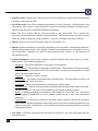
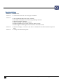
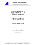
User Manual Salt Lake City, UT, USA Document Version R01851_05 Contents Overview ............................................................................................................................. 3 Functionality ..................................................................................................................... 3 Help ................................................................................................................................................. 4 Close ............................................................................................................................................... 4 Time ................................................................................................................................................ 4 Priority ........................................................................................................................................... 5 Opers............................................................................................................................................... 5 Trial................................................................................................................................................. 6 Elec ................................................................................................................................................. 7 Adc2phys....................................................................................................................................... 7 LowCorner .................................................................................................................................... 8 Signal .............................................................................................................................................. 8 Filter................................................................................................................................................ 9 List ................................................................................................................................ 9 Set ............................................................................................................................... 10 Custom ........................................................................................................................ 10 Cont.............................................................................................................................................. 12 Digin ............................................................................................................................................ 13 Bit-Change .................................................................................................................. 13 Digout .......................................................................................................................................... 13 Spike ............................................................................................................................................ 14 Stim .............................................................................................................................................. 15 Stimres ........................................................................................................................ 15 Stimulation String ....................................................................................................... 16 StimSeq ....................................................................................................................... 17 Enable ......................................................................................................................... 22 Module Enable ............................................................................................................ 22 Fast Settle ................................................................................................................................... 23 Stim............................................................................................................................. 23 Digin ........................................................................................................................... 23 Demos................................................................................................................................. 24 Walkthrough .............................................................................................................................. 24 Stimui GUI................................................................................................................................. 24 Real-time modulation of stimulation parameters ........................................................... 26 Revision History ............................................................................................................ 27 Xippmex User Manual Document Version R01851_05 ii Overview Ripple has developed a MATLAB interface to Trellis and the Grapevine Neural Interface Processor (NIP) called Xippmex. The name, Xippmex, is derived for the communication protocol used by the NIP and Trellis which is known as the eXensible Instrument Processing Protocol or XIPP. Xippmex facilitates data retrieval inside MATLAB, control of stimulation, control of signal streams, and recording. Using Xippmex, most of the functionality available in Trellis can be performed programmatically by writing simple MATLAB scripts. Xippmex allows for the creation of simple automation of experiments or building complex XIPP applications inside MATLAB. This document describes the full functionality of the Xippmex package with basic usage statements as well as fully-featured examples. The Xippmex installation is provided with the Trellis software suite, available on the Ripple downloads webpage. An example script that executes multiple Xippmex function calls in a sequence similar to common stimulation and recording scenarios is provided in the Trellis installation directory (‘…\Trellis\Tools\xippmex\ xippmex_walkthrough.m). In addition, the Xippmex package includes an open source MATLAB GUI application built on Xippmex (stimui), additional example scripts, and several utility scripts. These tools should get any experiment developer off the ground quickly. Please direct any Xippmex questions or issues to [email protected]. Installation Note: Xippmex currently requires the installation of Visual C++ Redistributable for Visual Studio 2008, though this is generally included with Windows 7. However, this package can be downloaded in x86 and x64 versions. Functionality Xippmex is a MEX based MATLAB interface to the NIP and provides access to data streams and control of stimulation. Xippmex is a MATLAB command that accepts the following command strings: ‘help’, ‘close’, ‘time’, ‘priority’, ‘opers’, ‘trial’, ‘elec’, ‘adc2phys’, ‘lowcorner’, ‘signal’, ‘filter’, ‘cont’, ‘spike’, ‘digin’, ‘digout’, ‘stim’, and ‘stimseq’. Each command is discussed in the following sections. Additionally, each command includes a usage string which can generally be found by executing the command with no additional parameters. 3 Document Version R01851_05 Xippmex User Manual Help ‘help’ displays a list of possible Xippmex commands. Most commands contain a usage statement that is displayed when the command is run with no parameters. usage: xippmex(cmdstr [, args]) Examples >> xippmex('help') 'close' - close UDP socket and delete cached data 'time' - display latest NIP time 'priority' - change xippmex thread priority 'opers' - find Trellis operators on the network 'trial' - control file save on Trellis operators 'elec' - retrieve electrode numbers by type of headstage. 'signal' - enable or disable signals 'filter' - modify and retrieve filter information 'cont' - get continuous data 'spike' - get recent spike or stim counts and times 'digin' - retrieve digital inputs 'digout' - control digital outputs 'stim' - send stim control string 'stimseq' - complex control of stimulation 'fastsettle' - control fast settle on front ends 'adc2phys' – change adc bit resolution for electrode 'lowcorner' – change hardware filter low-corner for electrode For more info, type command strings without arguments Close The ‘close’ command stops the XIPP listening thread and closes the receiving and sending UDP sockets. In addition, all cached data and other buffers are cleared. Usage xippmex(‘close’); Xippmex sockets are closed and buffered data is cleared. Time The ‘time’ command retrieves the most recently received NIP time, which is the number of clock cycles at 30 kHz (33.3 µs per cycle) that have occurred since the NIP was started. Usage time = xippmex(‘time’); Output time Most recent NIP time. NIP time represents the number of 30 kHz clock ticks since the NIP has been turned on. Examples >> xippmex('time') / 30000 / 60 ans = 34.2841 In this example, the running time of the NIP is calculated in minutes. Xippmex User Manual Document Version R01851_05 4 Priority The ‘priority’ command displays and modifies the priority of the underlying Xippmex thread. Modifying the thread priority is generally not required and is considered an advanced feature. However, there may be cases where Xippmex’s thread causes a system to stall or competes with other time sensitive processes. Warning: If Xippmex’s underlying thread is set low, it is likely that data will be lost. Note: This command is only available on Windows machines. Usage priority = xippmex('priority', [new_priority]); Input new_priority Output priority Optional. Desired thread priority. Must be one of ‘time-critical’, ‘highest’, ‘above’, ‘normal’, ‘below’, or ‘lowest’. If specified, priority is set to a new priority; if left empty, current priority is returned. If new_priority is not specified, the current thread priority is provided as a string. Will be one of the possible options found in the definition of the new_priority variable. If new_priority is provided, there is no returned value. Examples This example shows the current priority, which is the default, time-critical. >> xippmex('priority') ans = time-critical In this example, the thread priority is changed from time-critical to normal. >> xippmex('priority') ans = time-critical >> xippmex('priority', 'normal') Opers The ‘opers’ command retrieves the identification numbers of current running instances of Trellis on the instrument network. This number may range from 129 to 254 and is the last octet of the computer’s IPv4 address that is running Trellis. Usage opers = xippmex(‘opers’); Output opers Array of all Trellis operators’ ID on the instrument network. The operator ID is the last octet of the computer running Trellis’ IPv4 address. Examples >> xippmex('opers') ans = 205 In this example, ‘opers’ shows that there is one running instance of Trellis on the instrument network with an ID 205, corresponding to an IP address of 192.168.42.205. 5 Document Version R01851_05 Xippmex User Manual Trial The ‘trial’ command allows for the control of data recording through open instances of Trellis. Note: 'Enable Remote Control' must be selected in Trellis File Save before Xippmex can control Trellis File Save options. Usage trial_descriptor = xippmex('trial', operator, [status, [file_name_base, [auto_stop_time, [auto_incr, incr_num]]]]); Input Input operator status Input file_name_base Input auto_stop_time Input auto_incr Input incr_num Output trial_descriptor Trellis operator ID, may be the result of the command ‘opers’ (described above). Optional. Recording status, must be one of ‘recording’, ‘stopped’, or ‘paused’. If not specified, this parameter will not be changed. Optional. Full path of base file name for recording. Resulting files will be file_name_base.nev, file_name_base.ns2, etc. If not specified, this parameter will not be changed. Optional. Time to automatically stop recording(s) in seconds. If not specified, this parameter will not be changed. If set to 0, auto stop will be disabled. Optional. Boolean. If set to 1, output file name will be appended by a recording index. The appended string will always be four digits long, padded to the left with zeroes. If set to 0, auto increment will be disabled. Optional. Current value of increment number. If not specified, this parameter will not be changed. Structure describing Trellis file recording, with fields ‘status’, ‘file_name_base’, ‘auto_stop_time’, ‘auto_incr’, and ‘incr_num’ Examples >> xippmex('trial', 205) ans = status: 'stopped' filebase: 'C:\Users\Mitch\Trellis\dataFiles_20140106\datafile' auto_incr: 1 stop_time: 0 incr_num: 1 This example polls the current recording parameters of the Trellis instance with ID 205. >> xippmex('trial', 205, 'recording', [], 30) ans = status: 'recording' filebase: 'C:\Users\Mitch\Trellis\dataFiles_20140106\datafile' auto_incr: 1 stop_time: 30 incr_num: 2 This example starts a recording that will stop automatically after 30 seconds of without modifying any of the other recording parameters. Xippmex User Manual Document Version R01851_05 6 Elec The ‘elec’ command returns a MATLAB array of electrode IDs for the current NIP setup. Channels of Front Ends attached to port A of the first NIP are numbered 1-128, then 129-256 for port B, etc. Front End channel numbers range from 1-5120 to allow for recording from multiple NIPs by one computer running Trellis, which will be enabled in a future software release. Analog input channels are numbered 10241-10270 in the following order: SMA inputs 1-4, micro-D grouped inputs 1-24, then the 2 line-level audio inputs. Usage elecs = xippmex(‘elec’, type); Input type Output elecs String corresponding to Front End type. Possible types are ‘stim’, ‘micro’, ‘nano’, ‘surf’, ‘EMG’, ‘analog’, or ‘all’. Note: ‘micro’ is used for Micro and Micro HV Front Ends, and ‘surf’ is used for Surf S and Surf D Front Ends. Array of 1-indexed electrodes IDs. Examples >> elecs = xippmex(‘elec’, ‘stim’); This returns all the electrode IDs for all Micro+Stim Front Ends. Adc2phys The ‘adc2phys’ command sets the recording resolution for the analog-to-digital converter of Nano2 and Micro2 style Front Ends. This command is applied on a per-Front End basis; i.e. all channels on a particular Front End are set to the ‘bitres’ recording resolution by setting any electrode on that Front End. The current ‘bitres’ setting will be returned if the ‘bitres’ parameter is not specified. Setting the recording resolution to 1 corresponds to 0.125 µV/bit (± 4 mV range), 2 corresponds to 0.25 µV/bit (± 8 mV range), and 3 corresponds 0.50 µV/bit (± 16 mV range). At the highest resolution, 0.50 µV/bit, the linear range of recordings is ± 12 mV, where recordings above these levels will have nonlinear gains. Note: When the Grapevine is initially powered on, the default setting of 0.25 µV/bit will be set on all Nano2 and Micro2 style Front Ends. Usage output = xippmex(‘adc2phys’, elecs, [bitres]) Input Input elecs bitres Output output 1-indexed array of desired electrode(s). Optional. Scalar value representative of the desired recording resolution. 1 = 0.125 µV/bit, 2 = 0.25 µV/bit, 3 = 0.50 µV/bit. If no bitres parameter is sent, the current bitres setting is returned. Examples >> xippmex(‘adc2phys’, 10, 1) This sets the Front End associated with channel 10 (the first Front End on port A) to have recording resolution of 0.125 µV/bit. 7 Document Version R01851_05 Xippmex User Manual LowCorner The ‘lowcorner’ command sets the hardware high-pass filter on the Nano2 and Micro2 style Front Ends. This command is applied on a per-Front End basis; i.e. all channels on a particular Front End will have the same high-pass filter corner setting when the command is applied to any channel of that Front End. are set to the ‘lowcorner’ recording resolution by setting any electrode on that Front End. The current ‘lowcorner’ setting will be returned if the ‘lc_index’ parameter is not specified. Setting the lc_index parameter to 1 sets the low corner to 0.1 Hz {2 = 0.5 Hz, 3 = 1.0 Hz, 4 = 2.0 Hz, 5 = 10 Hz, 6 = 20 Hz, 7 = 50 Hz, 8 = 100 Hz}. Note: The actual low corner on any specific Nano2 or Micro2 will be within ±25% of these values. Note: When the Grapevine is powered on, the hardware high-pass filter low corner on all Nano2 and Micro2 Front Ends will be initialized to 0.1 Hz. Usage output = xippmex(‘lowcorner’, elecs, [lc_index]) Input Input elecs lc_index Output output 1-indexed array of desired electrode(s). Index of low corner filter value desired. [1 = 0.1 Hz, 2 = 0.5 Hz, 3 = 1.0 Hz, 4 = 2.0 Hz, 5 = 10 Hz, 6 = 20 Hz, 7 = 50 Hz, 8 = 100 Hz] If no index parameter is sent, the current low corner index is returned. Examples >> xippmex(‘lowcorner’, 10, 3) This sets the Front End associated with channel 10 (the first Front End on port A) to have a hardware filter low corner of 1 Hz. Signal The ‘signal’ command enables and disables data streams on the NIP and retrieves information about which streams are available for a given electrode and which streams are enabled. Note: Only the ‘stim’ and ‘spk’ data streams can be enabled and disabled on a per-channel basis. All other data streams are enabled and disabled on a per-Front End basis when any channel is used for ‘elecs’ input. Usage output = xippmex(‘signal’, elecs, [stream, [values]]) Input Input elecs stream Input values Output output Xippmex User Manual 1-indexed array of desired electrode(s). Optional. Name of data stream. If empty, this command will return the names of all the possible streams for the requested electrodes. Optional. Binary values to enable or disable streams. If this is a scalar, this value will be used for all electrodes in ‘elecs’. If an array, it must be the same length as ‘elecs’. If values is not specified, the state of the stream specified in ‘stream’ is returned for each electrode. If all ‘elecs’, ‘stream’, and ‘values’ are specified, no output is provided. If only ‘elecs’ and ‘stream’ are provided, the state of each electrode in ‘elecs’ is returned. If only ‘elecs’ is specified, the string for each stream is provided for each electrode in cell arrays. Document Version R01851_05 8 Examples >> xippmex('signal', 1) ans = 'raw' 'stim' 'hi-res' 'lfp' 'spk' Return the names of all data streams for electrode 1. >> xippmex('signal', 1:2, 'spk', [0,0]) Turn off spike data streams for electrodes 1 and 2. >> xippmex('signal', 1, 'raw') ans = 0 Retrieve the state of the ‘raw’ data stream for electrode 1, which is off in this case. Filter The ‘filter’ command displays the status of all the filtered streams and allows the selection of filters as well as the application of custom filters designed in MATLAB. Each data stream, aside from the ‘raw’ streams, is filtered online on the NIP before being published on the instrument network. Each filtered stream may have one band pass style filter as well as an independent notch or comb style to target 60 Hz noise and its harmonics (or 50 Hz for EU customers). The filter command has three distinct subcommands, ‘list’, ‘set’, and ‘custom’. Each of these is discussed in the following sections. List The ‘list’ subcommand returns the types of filters available, the details of the preset filters for each type of filter, and which filter is currently selected by the NIP. Usage filter_string = xippmex(‘filter’, ‘list’, elec); Input Output elec filter_string 1-indexed desired electrode. Cell array of stings returning possible filter types. [selection, filters] = xippmex(‘filter’, ‘list’, elec, filter type, [select]); 9 Input Input elec filter_type Input select Output Output selection filters 1-indexed desired electrode. Optional. Name of filter to list. If not specified, a list of filter names is provided for the electrode. Optional. If provided, only information about the filter corresponding to ‘select’ is returned in filters. A scalar indicating which possible filter for the specified ‘filter_type’ is selected. An array of structures holding information about selectable filters. If ‘select’ is specified, only the requested filter data is returned. Document Version R01851_05 Xippmex User Manual Examples >> xippmex('filter', 'list', 1) ans = hires' 'hires notch' 'lfp' 'lfp notch' 'spike' This example returns the possible filters for electrode 1. >> [selection, filters] = xippmex('filter', 'list', 1, 'hires'); In this example, the list of available ‘hires’ filters are retrieved for electrode 1. ‘selection’ is a scalar that shows which filter is currently selected. The returned ‘filters’ is an array of MATLAB structures holding the filter parameters, including the filter coefficients. Set The ‘set’ subcommand allows the end user to choose among the preset filters on the NIP for each filter type. Usage xippmex(‘filter’, ‘set’, elec, filter_type, value) Input Input Input elec filter_type value 1-indexed desired electrode. Name of filter type to modify Filter selection for given filter type Examples >> xippmex('filter', 'set', 1, 'hires', 1) In this example, the hires streams filter for electrode 1 is changed from 3 to 1. Custom The sub-command ‘custom’ allows for custom filters designed by an end user to be added to any of the currently available filters. The ‘custom’ filter is always the last filter of the selectable filters. To enable it, first the custom filter must be saved, with the ‘custom’ command, then selected, with the ‘set’ command. A filter structure must be created by the user that contains fields matching those returned in the filter structures returned from the ‘list’ subcommand. The actual filter coefficients must be specified using second order sections (SOS) matrices. See the below examples for more information. Usage xippmex(‘filter’, ‘custom’, elec, filter_type, filter_struct) Input Input Input elec filter_type Filter_struct Xippmex User Manual 1-indexed desired electrode. Name of filter type to modify. Filter selection for given filter type. The filter_struct must have the following fields: ‘label’, ‘lowCutoff’, ‘highCutoff’, ‘center’, ‘centerOrder’, ‘centerFlags’, ‘lowOrder’, ‘lowFlags’, ‘highOrder’, ‘highFlags’, ‘maxStages’, ‘numStages’, ‘sos’. NOTE: ‘numStages’ must match the rows in ‘sos’ and must not exceed ‘maxStages’. Document Version R01851_05 10 Examples >> [~, filters] = xippmex('filter', 'list', 1, 'hires'); >> filters(6) ans = label: 'Custom' lowCutoff: 0 highCutoff: 0 center: 0 centerOrder: 0 centerFlags: 0 lowOrder: 0 lowFlags: 0 highOrder: 0 highFlags: 0 maxStages: 4 numStages: 0 sos: [0x6 double] >> xippmex('filter', 'custom', 1, 'hires', filters(3)); >> [~, filters] = xippmex('filter', 'list', 1, 'hires'); >> filters(6) ans = label: '0.3-250 Hz' lowCutoff: 0.3000 highCutoff: 250 center: 0 centerOrder: 0 centerFlags: 0 lowOrder: 1 lowFlags: 0 highOrder: 4 highFlags: 0 maxStages: 4 numStages: 2 sos: [2x6 double] >> xippmex('filter', 'set', 1, 'hires', 6); In this example, the third filter from the hires stream is taken and set as the custom filter. Then the custom filter is enabled. >> [z, p, k] = butter(4, 125/(2000/2), 'low'); >> sos = zp2sos(z, p, k); >> filter_struct = struct('label', 'myFilter', 'lowCutoff', 0.3, ... 'highCutoff', 125, 'center', 0, 'centerOrder', 0, ... 'centerFlags', 0', 'lowOrder', 1, 'lowFlags', 0, ... 'highOrder', 4, 'highFlags', 0, 'maxStages', 4, ... 'numStages', 2, 'sos', sos); >> xippmex('filter', 'custom', 129, 'lfp', filter_struct); In this example, a filter is designed with MATLAB’s butterworth function and the SOS coefficients are calculated. The required filter structure is built and then set with the ‘custom’ command. 11 Document Version R01851_05 Xippmex User Manual Cont The ‘cont’ command returns the data from continuous data streams such as lfp, raw, or hi-res. To facilitate this, Xippmex maintains a five second circular buffer for all enabled streams. Continuous data may be retrieved directly off the top of the buffer or by a known NIP timestamp. Recording electrode channels are numbered 1-5120 (1-128 on port A, 129-256 on port B, etc.) and analog input channels are numbered 10241-10270. Usage [data, timestamp] = xippmex(‘cont’, elec, duration, stream_type, [NIP timestamp]) Input Input Input elec duration stream_type Input NIP timestamp Output data Output timestamp 1-indexed array of desired electrode(s). Length of requested data (ms). String defining data stream type. Generally, should be one of ‘raw’, ‘lfp’, and ‘hi-res’. Possible streams can be found in the ‘signal’ command. Optional. If specified, ‘cont’ will return data starting from the given NIP timestamp. If empty, the most recent data will be retrieved. The timestamp is based on NIP 30 kHz clock ticks. MATLAB array containing requested data (µV for neural data, mV for analog I/O inputs). The returned dimensions will be (length of elec) x (sample frequency x duration). LFP streams sample at 1 kHz, hi-res streams sample at 2 kHz, and raw streams sample at 30 kHz. Timestamp for first sample of retrieved data. The timestamp is based on NIP 30kHz clock ticks. Examples >> [data, ts] = xippmex(‘cont’, 1, 100, ‘lfp’); This returns 100 ms of lfp data for Front End channel 1, along with the NIP timestamp. >> data = xippmex(‘cont’, [1:3], 100, ‘raw’, 397881690); In this example, 100 ms of raw data is retrieved simultaneously for electrodes 1, 2, and 3 beginning at NIP clock cycle 397881690. Xippmex User Manual Document Version R01851_05 12 Digin The ‘digin’ command returns events triggered on the Digital I/O Front End. Similar to spike data, xippmex maintains a circular buffer of 1024 digital events. This buffer is cleared when data is retrieved. If more than 1024 events are received by the NIP between ‘digin’ calls, only the most recent 1024 triggered digital events are returned, though the returned count will always reflect the current number of triggered events. Usage [count, timestamps, events] = xippmex(‘digin’) Output Output count timestamps Output events The number of digital events received since the last ‘digin’ call. Array of length ‘count’ or 1024, whichever is smaller, containing the NIP timestamps for each returned event. The timestamp is based on NIP 30-kHz clock ticks. Array of MATLAB structures containing digital event data. Fields are ‘reason’, ‘sma1’, ‘sma2’, ‘sma3’, ‘sma4’, and ‘parallel’. The fields ‘sma1’ through ‘sma4’ and ‘parallel’ hold unsigned 16-bit integer values for the corresponding input. The ‘reason’ field is a bit mask showing which input triggered the digital event. 1 corresponds to the parallel port. 2, 4, 8, 16 refer to sma inputs 1, 2, 3, and 4 respectively. 32 refers to a digital output marker created when using the ‘digout’ command. Bit-Change The ‘digin’ command has a subcommand, ‘bit-change’, that allows a user to toggle between capturing digital inputs from the parallel port either with the strobe pin or when any bit on parallel port changes. If this property is set to true, the digital parallel port input is captured anytime a bit changes. If the property is set to false, digital parallel port input is only captured if the strobe line is triggered. Usage xippmex(‘digin’, ‘bit-change’, 1); This sets the Digital I/O to capture the state of the 16-bit parallel port anytime a bit changes on that port. Digout The ‘digout’ command controls digital output ports on the Digital I/O Front End. The supply voltage for the digital output pins is 3.3 V. 16-bit unsigned integers may be set on the output parallel port. Usage xippmex(‘digout’, outputs, values) Input outputs Input values List of outputs to control. 1-4 control SMA outputs 1-4. Specifying output 5 controls the output parallel port. List of values to set at ports. 1-4 are binary. I.e., 0 will set them to 0, any positive value will set the port to the supply voltage. If the output parallel port is specified, the value may be a 16-bit unsigned integer. The length of values must equal the length of outputs. Examples >> xippmex(‘digout’, 1:2, [1, 1]); pause(0.001); xippmex(‘digout’, 1:2, [0,0]); Assuming that output 1 was initially low, this set of commands will approximate a TTL pulse. The width of the TTL will be determined by the resolution of the pause command and may be system dependent. >> xippmex(‘digout’, 5, hex2dec(‘CAFE’)); This example sets the parallel port output to 0xCAFE. 13 Document Version R01851_05 Xippmex User Manual Spike The ‘spike’ command returns the count, timestamps, waveforms for spikes or stimulation events, and unit classifiers for the requested electrodes. For each electrode, data for up to 1024 spike and stim markers are stored in a circular buffer. When the spike command is called, the spike or stim marker data is retrieved and the buffers are flushed. If more than 1024 spike or stim markers are received between consecutive ‘spike’ calls, only the most recent 1024 spikes are returned. However, the returned spike counts will not be capped and will reflect the current number of triggered spike events. Spike and stim marker data can be retrieved for several electrodes at a time, and as such, data is returned in cell arrays. Usage [count, timestamps, waveforms, units] = xippmex(‘spike’, elecs, use_stim) Input Input Output Output elecs use_stim count timestamps Output waveforms Output units 1-indexed array of desired electrode(s). 0 for spike data, 1 for stim (0 is default). Array of same length as elecs, holding the number of spikes received since last call. Cell array of size matching elec, holding arrays of NIP timestamps for each received spike. Each array will have ‘count’ timestamps. The timestamp is based on NIP 30-kHz clock ticks. Cell array of size matching elec, holding arrays of length ‘count’ that contain 52-element arrays corresponding to spike or stim waveforms (µV or V). Cell array of size matching elec, holding arrays of unit classification based on unit sorting set in the Trellis Spike Scope application. Unit values are: 0 – unsorted, 1 – blue, 2 – green, 3 – yellow, 4 – purple. Examples >> [count, timestamps, waveforms] = xippmex(‘spike’, 5, 1); Retrieves the number of data packets, timestamps, and stimulation data for electrode 5. >> [count, timestamps, waveforms, units] = xippmex(‘spike’, 1:10, 0); Return the counts, timestamps, neural data waveforms, and unit classifiers for electrodes 1 through 10. Xippmex User Manual Document Version R01851_05 14 Stim The ‘stim’ command creates biphasic stimulation trains of arbitrary length and frequency while using a Micro+Stim Front End. Though the basic structure of this command is very simple, relatively complex stimulation is possible including interleaving stimulation between multiple electrodes and bipolar stimulation. The ‘stim’ command also includes a subcommand that allows for the control of the NIP’s global stim enable property. This may be used to immediately stop stimulation. By default, the NIP’s stimulation enable property will be set to false. In normal stimulation usage, xippmex will set the NIP’s stimulation enable property to on and after the stimulation has finished will set the property back to off. Note: The amplitude of stimulation is specified with unitless values between 0-127. The amount of current produced by step may vary for each Front End and is a value that must be specified by Ripple. If this parameter is not known, contact [email protected] to obtain the value for your specific hardware. Stimres For Nano2+Stim and Micro2+Stim Front Ends, there is a ‘stim’ subcommand that sets the stimulation current step-size. This command is applied on a per-Front End basis; i.e. all channels on a particular Front End are set to the ‘stimres’ stimulation step-size by setting any electrode on that Front End. The current ‘res’ setting will be returned if the ‘stimres’ parameter is not specified. Setting the parameter to 1 corresponds to 1 µA/step, 2 is 2 µA/step, 3 is 5 µA/step, 4 is 10 µA/step, and 5 is 20 µA/step. Note: When using the highest step-size, 20 µA/step, the range of stimulation output is only ±75 steps. Note: When the Grapevine is initially powered on, the default setting of 10 µA/step will be set. Usage output = xippmex(‘stim’, ‘res’, elecs, [stimres]) Input Input elecs stimres Output output 1-indexed array of desired electrode(s). Optional. Scalar value representative of the desired recording resolution. 1 = 1 µA/step, 2 = 2 µA/step, 3 = 5 µA/step, 4 = 10 µA/step, 5 = 20 µA/step. If no bitres parameter is sent, the current bitres setting is returned. Examples >> xippmex(‘stim’, ‘res’, 10, 3) This sets the Front End associated with channel 10 (the first Front End on port A) to have a stimulation step-size of 5.0 µA/step. 15 Document Version R01851_05 Xippmex User Manual Stimulation String If the second parameter is a valid stimulation string as defined below, xippmex will produce a biphasic pulse pair, with a fixed interphase interval of 66 µs (2 clock cycles). Usage xippmex(‘stim’, stim_string); Input stim_string String containing stimulation parameters. See below for detailed discussion. Stimulation String Parameters A valid stimulation string is a list of parameters separated by semi-colons, with parameter values organized by electrode separated by commas. For example, the string: ‘Elect=9,10,;TL=1000.0,1000.0,;Freq=30,30,;Dur=0.2,0.2,;Amp=10,20,; TD=0.0,0.0,;FS=0.0,0.0,;PL=1,1,;’ creates symmetric biphasic pulse pairs on electrodes 9 and 10 at 30 Hz. The phases are 200 µs in duration and the train will run for 1 second. Electrode 9 will have amplitude of 10, and electrode 10 will have amplitude of 20. The following table has the details of each parameter. Elect TL Freq Dur CathDur AnodDur Amp CathAmp AnodAmp TD FS PL “Electrodes.” 1-indexed list of desired electrode(s). The length of this list must match the length of the lists for all other parameters. “Train Length.” Length of train of pulse in (ms). “Frequency.” Frequency of the resulting pulses (Hz). “Duration.” Duration of both phases of a biphasic pulse (ms). Using “CathDur” and “AnodDur” in place of this parameter is valid. “Cathodic Duration.” The duration of the cathodic phase only (ms). This parameter conflicts with Dur and must be used with AnodDur. “Anodic Duration.” The duration of the anodic phase only (ms). This parameter conflicts with Dur and must be used with AnodDur. “Amplitude.” The current amplitude of a symmetric biphasic pulse. Amplitude must be in the range 0-127. The current output per step is set at the time of Front End production and will be in the range of 1-25 µA per step. Using “AnodAmp” and “CathAmp” in place of this parameter is valid. “Cathodic Amplitude.” The current amplitude of the cathodic phase only. See “Amp” for more discussion of the value of this parameter. This parameter conflicts with Amp and must be used with AnodAmp. “Anodic Amplitude.” The current amplitude of the anodic phase only. See “Amp” for more discussion of the value of this parameter. This parameter conflicts with Amp and must be used with AnodAmp. “Train Delay.” Time to delay a stimulation pulse (ms). This parameter may be used for interleaving stimulation. “Fast Settle.” Duration of time to fast settle after the full biphasic pulse (ms). “Polarity.” In general, this command produces biphasic pulses. If polarity is set to 1, the stimulation will be cathodic first. If 0, the stimulation will be anodic first. This parameter is useful for creating bipolar stimulation of neighboring electrodes. Xippmex User Manual Document Version R01851_05 16 Examples In addition to the following examples, the external function stim_param_to_string.m and the xippmex application stimui.m can help to create useful stimulation parameter strings. >>xippmex(‘stim’,‘Elect=9,10,;TL=1000.0,1000.0,;Freq=30,30,;Dur=0.2,0.2,;Amp=20,20, ;TD=0.0,0.0,;FS=0.0,0.0,;PL=1,0,;’); This command will produce bipolar stimulation between electrodes 9 and 10 with a frequency of 30 Hz and a train length of one second. In this case, electrode 9 will have the cathodic phase first and electrode 10 will have the anodic phase first. So for the first phase, current will flow from electrode 10 into electrode 9. >>xippmex(‘stim’,‘Elect=1,;TL=1000.0,;Freq=60,;CathDur=0.2,;AnodDur=0.4,;CathAmp=20 ,;AnodAmp=10,;TD=0.0,;FS=0.0,;PL=1,;’); In this example, an asymmetric biphasic pulse is charged balanced with a 2:1 ratio, where the anodic phase is twice as long as the cathodic phase, though with half the amplitude. >>xippmex(‘stim’,‘Elect=9,10,;TL=1000.0,1000.0,;Freq=30,30,;Dur=0.2,0.2,;Amp=20,20, ;TD=0.0,15.0,;FS=0.0,0.0,;PL=1,1,;’); In this example, symmetric biphasic stimulation is produced on electrodes 9 and 10, though interleaved, with pulses on electrode 10 delayed by 15 ms. StimSeq The ‘stimseq’ command is an advanced command that allows for low-level control of stimulation via the NIP and Stimulation Front Ends (e.g., Micro+Stim). Careful use of this command can produce almost any stimulation waveform, with a temporal resolution as small as 1 µs. The construction of stimulation trains includes two main control blocks. The overall control word specifies the electrode, period of stimulation, and the number of times that the stimulation waveform will be repeated. The second control word defines the repeated waveform. Figure 1 illustrates the breakdown of the overall language. Stimulation will be executed by the NIP as soon as it is received. The handling of time critical pieces must be performed in MATLAB. Additionally, successive stimulation commands will clobber any existing stimulation and will also occur immediately, potentially disrupting charge balancing. As such care must be taken when sending a series of stimulation commands. 17 Document Version R01851_05 Xippmex User Manual Stimulation blocks define stimulation waveform The control word specifies electrode, period and number of repeats Figure 1. Control word and stimulation diagram In MATLAB, the control word consists of four fields ‘elec’, ‘repeats’, ‘period’, and ‘action’, and is packed in a structure, along with the ‘seq’ field, that specifies the actual stimulation waveform. Each required field is defined in the following table. elec repeats period action seq Scalar, 1-indexed electrode ID. The number of repetitions of the stimulation. In order to perform stimulation this number must be at least 1. The number of repeats cannot be greater than 4095. The period at which to repeat stimulation in units of 33.3 µs (one clock cycle at 30 kHz). Optional. Command determining how the stimulation is processed on the NIP. Must be one of the following ‘immed’, ‘curcyc’, ‘allcyc’, or ‘at-time’. See Section ‘action’ below. If not specified, ‘immed’ is used. Array of structures that defines the stimulation waveform. The ‘action’ field of the stimulation control word tells the NIP how to process the stimulation command. This allows a user to immediately begin stimulation, queue stimulation, or execute stimulation at a defined NIP time. These commands are passed to xippmex as a string and must be one of ‘immed’, ‘curcyc’, ‘allcyc’, or ‘at-time’. immed – Process the command immediately This command will be processed as soon as the NIP receives the command. However, in the case that the new command would interrupt an ongoing stimulation waveform and disrupt charge balancing, the new stimulation train will be placed after the current waveform. Using this command could potentially put two stimulation pulses very close together causing an abrupt change in stimulation frequency. The ‘immed’ command will clear any stimulation that is currently queued. curcyc – Process the command after current cycle This command will interrupt any ongoing stimulation. However, instead of executing the new waveform immediately when it is received, the NIP attempts to blend the two frequencies. The new stimulation pulses will be placed such that the time between successive pulses is never less than the updated frequency. If there is no ongoing stimulation when this command is received, ‘curcyc’ acts identically to ‘immed’. Xippmex User Manual Document Version R01851_05 18 allcyc – Queue stimulation after the current train This command will queue the new stimulation pattern directly after the current pattern has run through its entire train. If consecutive patterns are sent to the NIP with ‘allcyc’ they will be queued as they are received. The max queue depth is eight patterns. If more than eight patterns are received for a given electrode, the NIP will disable stimulation on that entire Front End. at-time – Apply stimulation pattern at a specified NIP time This command allows a user to specify a later NIP time for when a stimulation pattern will be executed. This command utilizes the ‘period’ field in the stimulation command word differently than the commands above. As such, only a 16-bit unsigned may be used with the ‘period’ field of this command. The ‘repeats’ filed of the command word is necessary but is ignored using ‘at-time’; thus stimulation trains are not possible with this command outright, though they may be generated using multiple stimulation pulses and pauses in the command sequences or by sending regular ‘at-time’ commands and updating the time with regular intervals. The incoming sequences will be executed when the value in the period field matches the lower 16-bits of the NIP time, or when tNIP&0xFFFF == period. Note: This requires that the NIP must receive ‘at-time’ commands no later than two seconds from the current NIP time (see ‘time’ command on page 1 for reference). As multiple commands are received they will be queued similar to using the ‘curcyc’ and ‘allcyc’ commands. Stimulation will be disabled on a Front End if a command is received too early to execute or if the queue depth is larger than eight. The ‘seq’ field specifies the waveform itself with an array of MATLAB structures. Each element in the array specifies a period of the stimulation where the stimulation parameters are constant. The required fields for stimulation control are the fields ‘length’, ‘ampl’, ‘pol’, ‘enable’, ‘fs’, ‘delay’, and ‘ampSelect’. The following table outlines all the required fields in the structure, and Figure 2 provides an example of constructing a simple biphasic pulse pair. length ampl pol enable fs delay ampSelect The number of 33.3 µs units for this command (cannot be 0). Amplitude of current stimulation. Must be 0-127. The amount of current per step varies across Front Ends and is a number that is provided by Ripple with each Micro+Stim Front End. Polarity of stimulation. If 0, the resulting current will be negative, if 1, the resulting current will be positive. Specifies whether the next transition is to zero output (interphase interval) or positive/negative stimulation (anodic/cathodic). If there is not stimulation in this period, this should be 0. If current output is wanted, positive or negative, this should be 1. Enable fast settle during this stimulation period. Time to delay this word to become active in units 33.3 µs / 31 = 1.04 µs. This number must be between 0-31. This word allows for the control of stimulation at a temporal resolution of almost 1 µs but is only valid for particular waveforms. Choice of stimulation amp or neural amp. 0 for neural amp, 1 for stimulation amp. Note: The amplitude of stimulation is specified with unitless values between 0-127. The amount of current produced by step may vary for each Front End and is a value that must be specified by Ripple. If this parameter is not known, contact [email protected] to obtain the value for your specific hardware. 19 Document Version R01851_05 Xippmex User Manual Examples In this first example, the waveform described in Figure 2 is created with a frequency of 30 Hz and a train length of one second. A complex example is distributed with xippmex that produces sinusoidal stimulation of arbitrary frequencies and amplitudes. See the MATLAB function stim_sin.m for more information. 3 2 10 100 µs 1 200 µs A. The first, cathodic phase of the waveform can be created with length set to 6, pol set to 0, and enable set to 1. All other fields may be set to zero. B. The interphase interval can be created using length of 3 and setting amplitude to zero. All other fields may be set to zero. C. The last, anodic phase can be produced by matching the word from ‘A’ only with the pol field set to 1. Figure 2. A basic biphasic pulse pair can be constructed with three words, in this example: A, B, and C. % create the overall header values defining electrode, frequency, % and number of repeats. This will stimulate on electrode 1 at 30 % Hz for one second. cmd = struct('elec', 1, 'period', 1000, 'repeats', 30); % Create the first phase (cathodic) for stimulation. This has a % duration of 200 us (6 clock cycles at 30 kHz), an amplitude of % 10, and negative polarity. cmd.seq(1) = struct('length', 6, 'ampl', 10, 'pol', 0, ... 'fs', 0, 'enable', 1, 'delay', 0, 'ampSelect', 1); % Create the inter-phase interval. This has a duration of 100 us % (3 clock cycles at 30 kHz). The amplitude is zero. The % stimulation amp is still used so that the stim markers sent by % the NIP will properly contain this phase. cmd.seq(2) = struct('length', 3, 'ampl', 0, 'pol', 0, 'fs', 0, ... 'enable', 0, 'delay', 0, 'ampSelect', 1); % Create the second, anodic phase. This has a duration of 200 us % (6 cycles at 30 kHz), and amplitude of 10, and positive polarity. cmd.seq(3) = struct('length', 6, 'ampl', 10, 'pol', 1, ... 'fs', 0, 'enable', 1, 'delay', 0, 'ampSelect', 1); % Send the stimulation xippmex('stimseq', cmd); Xippmex User Manual Document Version R01851_05 20 In the second example, the use of the ‘delay’ field is demonstrated to produce a biphasic pulse with phases narrower than the 30 kHz clock cycles. Here, a symmetric biphasic pulse is created with 50 µs pulsewidth. Because this requires a temporal resolution less than 33.3 µs, the ‘delay’ parameter will need to be used. Figure 3 illustrates the needed words and boundaries on the 30 kHz clock. 33.3 µs 5 2 3 4 10 1 50 µs 100 µs Figure 3. Illustration of the required stimulation words needed to create a biphasic pulse with 50 µs phases. As this requires a temporal resolution finer than 33.3 µs, the delay parameter will be used. The dashed lines represent the 30 kHz clock. Each new color shows where a new stimulation word is used. % xippmex('stimseq') example producing a symmetric biphasic pulse with % phases of 50 us and an inter-phase interval of 100 us. This example % makes use of the stimulation control word's 'delay' field. % % single clock cycle in microseconds clock_cycle = 1 / 30 * 1000; % calculate the length of a single unit of delay in microseconds delay_length = 1 / 30 * 1000 / 32; % Setup the basic header elements. This will produce stimulation at 30 % Hz for one second cmd = struct('elec', 1, 'period', 1000, 'repeats', 30); % first command word. Produce 1 clock cycle worth of stimulation, for % 33.3 us of the first 50 us phase. cmd.seq(1) = struct('length', 1, 'ampl', 10, 'pol', 0, 'fs', 0, ... 'enable', 1, 'delay', 0, 'ampSelect', 1); % calculate the remaining duration of the cathodic phase. Because % this is less than one clock cycle period the delay field will need % to be used cath_remaining = 50.0 - clock_cycle; % the actual delay parameter must be an integer between 0 and 31 cath_delay = floor(cath_remaining / delay_length); % This word will produce the full cathodic phase and a bit of the % inter-phase interval. Here, the 'enable' field set to zero, sets % the pulse to start high and transition to off. cmd.seq(2) = struct('length', 1, 'ampl', 10, 'pol', 0, 'fs', 0, ... 'enable', 0, 'delay', cath_delay, 'ampSelect', 1); % The inter-phase interval is 100 us, so add two more full clock % cycles worth of stimulation for 66.6 us more. cmd.seq(3) = struct('length', 2, 'ampl', 0, 'pol', 0, 'fs', 0, ... 'enable', 0, 'delay', 0, 'ampSelect', 1); % calculate how much more of the inter-phase interval is remaining % being careful to account for the quantization of the delay at the % end of the cathodic phase 21 Document Version R01851_05 Xippmex User Manual ipi_remaining = 100.0 - (clock_cycle - cath_delay * delay_length) - ... 2 * clock_cycle; ipi_delay = floor(ipi_remaining / delay_length); % add this to the sequence list. Here the enable field sets the % pulse to start off and transition to on. cmd.seq(4) = struct('length', 1, 'ampl', 10, 'pol', 1, 'fs', 0, ... 'enable', 1, 'delay', ipi_delay, 'ampSelect', 1); % At this point there is not a full clock cycle's worth of stim left, % so the pulse will be finished with one use of the delay field anod_remaining = 50.0 - (clock_cycle - ipi_delay * delay_length); anod_delay = floor(anod_remaining / delay_length); % add the last command word cmd.seq(5) = struct('length', 1, 'ampl', 10, 'pol', 1, 'fs', 0, ... 'enable', 0, 'delay', anod_delay, 'ampSelect', 1); % fire off stimulation xippmex('stimseq', cmd); Enable If the second parameter of the ‘stim’ command is ‘enable’, xippmex will return or control the global stimulation enable property of the NIP. This functionality can be important if there is ever a need to immediately halt stimulation. Usage >> xippmex('stim', 'enable') ans = 0 Here, the NIP’s global stimulation enable is returned. “False” is the default setting for this property. >> xippmex('stim', 'enable', 0); In this example, the stimulation enable property is set to false. This can be used to immediately halt stimulation. Module Enable If the second parameter is ‘module-enable’, xippmex will return or control the enable status for a given electrode. Though the parameter is for a given electrode, the control is actually for the entire Front End that includes the given electrode. Usage >> xippmex('stim', 'module-enable', electrode, [value]); Examples >> xippmex('stim', 'module-enable', 1); ans = 0 This example returns the stim enable property of just the Front End associated with electrode 1, which is set to false. >> xippmex('stim', 'module-enable', 1, 1); This example sets the stim enable property of just the Front End associated with electrode 1 to be true (ON). Xippmex User Manual Document Version R01851_05 22 Fast Settle Xippmex can control the NIP’s fast settle capability, allowing for successful recordings within a millisecond of stimulation on neighboring electrodes. Fast settle may be set to occur directly after stimulation produced by the NIP or triggered off of digital events, useful if used with external stimulators. The fast settle period, or the length of time to settle the ADC, can also be set with this command. Stim The subcommand ‘stim’ sets fast settle triggering to occur from outgoing stimulation by the NIP. Fast settle may be triggered by any stim electrode on the NIP, by any stim electrode connected to the same front end port, or by a stim electrode on the same Front End. All Grapevine Front Ends support fast settle with the exception of the Surf D and EMG Front Ends. Usage xippmex(‘fastsettle’, ‘stim’, electrode, [source, [duration] ]); Input Input electrode source Input duration Scalar, 1-indexed electrode ID. Optional. Index of desired source. If not specified, the current source index is returned. These are 1-‘none’, 2-‘any front end’, 3-‘same front end port’, or 4-‘same front end’. Optional. Duration of fast settle in ms. If not specified the current fast settle value is returned. Examples >> xippmex(‘fastsettle’, ‘stim’, 1, 2, 0.5); This command will set fast settle for the Front End associated with electrode 1, to be triggered by stimulation on any Front End with a fast settle duration of 0.5 ms. >> [index, list] = xippmex(‘fastsettle’, ‘stim’, 1); This command will return the index selected and list of all available fast settle settings. Digin The subcommand ‘digin’ sets fast settle triggering to occur from a specified digital input. Usage xippmex(‘fastsettle’, ‘digin’, electrode, [source, [duration] ]); Input Input electrode source Input duration Scalar, 1-indexed electrode ID. Index of digital input used to trigger fast settle. The choices here are 1-‘none’, 2-‘Dig Input 1’, 3-‘Dig Input 2’, 4-‘Dig Input 3’, and 5-‘Dig Input 4’. Duration of fast settle in ms. Examples >> xippmex(‘fastsettle’, ‘digin’, 1, 3, 1.5); This command will set fast settle for the Front End associated with electrode 1, to be triggered by the Digital I/O Front End SMA input 2, with a fast settle duration of 1.5 ms. 23 Document Version R01851_05 Xippmex User Manual Demos This section contains demonstration programs built on the Xippmex interface that are included with xippmex. These are all open source and are great examples for a user developing custom MATLAB programs using xippmex. Walkthrough A xippmex walkthrough is included in the installation that demonstrates many of the functionality described earlier in this document. The walkthrough will demonstrate the following functionality: Initialize and close xippmex Find electrodes corresponding to different Front End types (Micro, Nano, Stim) Enable and Disable data streams Modify filters on the NIP data streams Configure Trellis data taking Create simple stimulation pattern Retrieve data and make a simple plot Stimui GUI The stimui MATLAB GUI allows for basic control of biphasic stimulation with symmetric anodic and cathodic phases with a constant 67-µs inter-phase interval. Provided here is a basic description of the functionality. Figure 4 shows the stimui window and may be used as reference for all of the following element descriptions. This application provides similar functionality, though with significantly less features, to the Trellis Stim application. In general, there is no reason to do stimulation with stimui rather than with Trellis, however it provides a fully functional example that could help in the development of future MATLAB applications based on Xippmex. Figure 4. stimui GUI Xippmex User Manual Document Version R01851_05 24 Stim Electrodes: Displays the 1-indexed electrode ID for all the Micro+Stim Front End stimulation electrodes connected to the NIP. Saved Electrodes: Lists all the stimulation parameters for saved electrodes. Add electrodes to this list using the “Save” button. Saving electrodes is required to stimulate on multiple electrodes at once. Each electrode may have independent stimulation parameters. Save: The “Save” button adds the selected electrode to the “Saved Stim” list or replaces the previously selected parameters with the current parameters. This button must be selected every time that a user wants to change the saved parameters. Selection of multiple electrodes is allowed. Remove: Remove the selected electrodes from the “Saved Stim” list. Bipolar: Bipolar stimulation is executed by stimulating on two electrodes with identical parameters, though with opposite polarities. The “Bipolar” button saves stimulation on two electrodes; however, one will have the “Cathodic First” check box selected and the other will not. See the discussion of this checkbox below. Channel Parameters: stimui always produces symmetric biphasic pulse pairs with a 67-µs interphase interval. The channel parameters are: o Amplitude – The current amplitude of each phase in microamperes. o Phase Duration – The duration of each phase in milliseconds. If this number is 200 microseconds, the entire stimulation waveform will be 467 microseconds, as each pulse corresponds to two equal phases and an interphase interval. o Frequency – Frequency of pulses in Hertz. o Train Length – The length of stimulation burst in milliseconds. The total number of pulses will be “Train Length” times “Frequency”. o Train Delay – Delay of the stimulation for interleaving in milliseconds. o Fast Settle Time – Add fast settle period after stimulation pulse in milliseconds, if the “Fast Settle” checkbox is selected. This value will be added after the complete stimulation pulse. o Enable – Enabling or disabling of stimulation of this channel in “Saved Stim” list. This allows for the stopping of stimulation of a given channel without having to erase saved stimulation parameters. o Cathodic First – If selected (by default), the first phase will be cathodic, otherwise the first phase will be anodic. Bipolar stimulation is done using nearby electrodes with identical parameters, but with one having the “Cathodic First” selected and one without, producing identical waveforms with opposite polarity. Fast Settle: If selected, electrodes in the fast settle list will have a fast settle period until after the stimulation pulse. 25 Document Version R01851_05 Xippmex User Manual Single Pulse: This checkbox forces the “Train Length” to be one period as determined by the “Freq” setting so that there will always be a single pulse. Stim Single: Sends stimulation commands on the selected electrode in the “Saved Stim” list. This command only works for single electrodes. Stim Saved: Sends stim commands for all the electrodes in the “Saved Stim” list. Fast Settle: Add electrodes to the list of fast settle electrodes. Print Stim String: Display the stimulation string for the xippmex ‘stim’ command. The stimui application makes use of the xippmex command ‘stim’ and the interface can quickly allow for the creation of fairly complex stimulation waveforms. Sometimes displaying this string can help in the development of new applications or to learn the stimulation string syntax. Real-time modulation of stimulation parameters There are three demos included in xippmex that make use of the ‘stimseq’ command to facilate real-time control of stimulation parameters. These demos are CLstim_AmplitudeModulation_32ch.m, CLstim_FrequencyModulation_32ch.m, and CLstim_PulsewidthModulation_32ch.m. All of these examples take an analog input and modulate a stimulation parameter based on that input, either amplitude, frequency, or the pulsewidth of the outgoing stimulation. These demos were developed and tested using FlexiForce sensors available at https://www.tekscan.com and are relatively cheap. However, they will work with any analog input and could be quickly modified for any style sensors. Xippmex User Manual Document Version R01851_05 26 Revision History 27 Version 01 Initial release Version 02 Clarifications made to the ‘elec’ and ‘signal’ commands Version 03 Version 04 Added the ‘adc2phys’, ‘lowcorner’, and ‘stimres’ commands for new Nano2 and Micro2 style Front Ends Version 05 Cleanup of all function descriptions Unit Classification added to the ‘spike’ command Note added for interphase interval when using stimString command Added the ‘fastsettle’ command Added ‘bit-change’ to the ‘digin’ command Included explanation of the ‘action’ field to the ‘stimseq’ section Included xippmex walkthrough and real-time demos to the Demos section Document Version R01851_05 Xippmex User Manual