1
Serial Interface FTA
for XYR 5000
User Manual
Revision 1.02
30 April 2007
34-XY-25-14
Copyright, Notices, and Trademarks
Printed in U.S.A. – © Copyright 2006 by Honeywell International Inc.
Revision 1.02 - 30 April 2007
While this information is presented in good faith and believed to be accurate,
Honeywell disclaims the implied warranties of merchantability and fitness for a
particular purpose and makes no express warranties except as may be stated in its
written agreement with and for its customer.
In no event is Honeywell liable to anyone for any indirect, special or consequential
damages. The information and specifications in this manual are subject to change
without notice.
Honeywell International Inc.
Honeywell Process Solutions
2500 W Union Hills Dr
Phoenix, Arizona 85027
(602) 313-5000
TABLE OF CONTENTS
INDEX OF TABLES .................................................................................................................................2
INDEX OF FIGURES................................................................................................................................2
REVISION HISTORY FOR DOCUMENT 34-XY-25-14 .......................................................................2
INTRODUCTION......................................................................................................................................2
SUPPORTING DOCUMENTATION .......................................................................................................2
OVERVIEW...............................................................................................................................................2
ELECTRICAL INTERFACES ..................................................................................................................2
REQUIRED HARDWARE........................................................................................................................2
REQUIRED SOFTWARE AND LCN RESOURCES...............................................................................2
INSTALLATION OVERVIEW STEPS ....................................................................................................2
GENERAL LAYOUT DIAGRAM............................................................................................................2
AVAILABLE BASE RADIO PARAMETERS .........................................................................................2
BASE RADIO HOLDING REGISTERS
2
TRANSMITTER DATA TABLE
2
DATA BASE STRUCTURE .....................................................................................................................2
ARRAY DATABASE STRUCTURE
2
EXTENDED DATABASE STRUCTURE
2
GRAPHICAL REPRESENTATION OF DATABASE STRUCTURE
2
DATA BASE UPDATE.............................................................................................................................2
REQUIRED DATABASE CONFIGURATION........................................................................................2
EXTENDED DATABASE CONFIGURATION.......................................................................................2
CONTROL CAPABILITIES .....................................................................................................................2
ERROR HANDLING.................................................................................................................................2
SYSTEM PERFORMANCE......................................................................................................................2
DATA BASE ORGANIZATION ..............................................................................................................2
ARRAYS REQUIRED FOR UP TO 5 TRANSMITTERS
2
ADDITIONAL ARRAYS REQUIRED FOR UP TO 25 TRANSMITTERS
2
TPS XYR DATABASE CONFIGURATOR .............................................................................................2
PURPOSE
2
OPERATION
2
INSTALLATION
2
EXECUTION
2
TPS / XYR 5000 DIAGNOSTIC SCHEMATIC .......................................................................................2
SAMPLE DATABASES AND CL ............................................................................................................2
SAMPLE xPM ARRAY DATABASE
2
SAMPLE xPM ALARMABLE FLAG POINT
2
SAMPLE xPM NON-ALARMABLE FLAG POINT
2
SAMPLE xPM NUMERIC POINT
2
SAMPLE xPM REGPV POINT
2
SAMPLE xPM PROCMOD POINT
2
SAMPLE xPM CL
2
DISPLAY DATABASE FILE
2
PRE-INSTALLATION CHECKLIST .......................................................................................................2
SETUP AND TROUBLE-SHOOTING GUIDE........................................................................................2
ORDERING INFORMATION ..................................................................................................................2
Revision 1.02
Serial Interface FTA for XYR 5000 User Manual - 34-XY-25-14
Page 3 of 91
30 April 2007
INDEX OF TABLES
Table 1 - Required Components.................................................................................................................................. 2
Table 2 - Transmitter vs. Array Requirements ............................................................................................................ 2
Table 3 - Base Transmitter Register Data ................................................................................................................... 2
Table 4 - Transmitter Modbus Addresses and Data .................................................................................................... 2
Table 5 - XYR Solution Point Types .......................................................................................................................... 2
Table 6 - Parameter Entries for Array Points .............................................................................................................. 2
Table 7 - Size and Configuration Table ...................................................................................................................... 2
Table 8 - Error Indications .......................................................................................................................................... 2
Table 9 - Files built by XYR Configurator ................................................................................................................. 2
Table 10 - Checks for Manual Point Name Changes .................................................................................................. 2
INDEX OF FIGURES
Figure 1 - FTA Connector ........................................................................................................................................... 2
Figure 2 - Base Radio Connections ............................................................................................................................. 2
Revision 1.02
Serial Interface FTA for XYR 5000 User Manual - 34-XY-25-14
Page 4 of 91
30 April 2007
REVISION HISTORY FOR DOCUMENT 34-XY-25-14
REVISION
1.0
1.01
1.02
Revision 1.02
DATE
19 May 2006
22 May 2006
30 April 2007
REASON
First Release.
Revise verbiage to make clear.
Add notes about data flags.
BY
Mike Stapley
Mike Stapley
Mike Stapley
Serial Interface FTA for XYR 5000 User Manual - 34-XY-25-14
Page 5 of 91
30 April 2007
INTRODUCTION
The purpose of this document is to provide a detailed user manual for the Honeywell Serial
Interface Field Termination Assembly (SI-FTA) to Honeywell’s XYR 5000 (XYR5000).
This document addresses all topics that affect the functionality of the interface including the
the communications protocol, parameter availability, data formats, system configuration,
and user interface. As well, the document provides instructions for configuration and
implementation of the device into the Honeywell TPS system. This document is not
intended to replace the manuals supplied with the TDC system that give proper instruction
on the installation and configuration of the required hardware. Neither does it supplant the
information provided in the Wireless Base Radio User Manual.
With the SI-FTA for the XYR 5000, Honeywell provides access to all the data remotely
available from the XYR 5000 and stores the data into arrays associated with the SI-FTA as
described later within this document. As a part of the XYR SI-FTA package, a database
builder executable is provided that will build the necessary TPS System database on the
Advanced Process Manager (APM) or HighPerformance Process Manager (HPM)
(hereinafter referred to collectively as xPM) (.EB files) for the array data and within the
specified limits of the xPM, also builds the .EB files and Control Language (.CL) files
requisite to move the data into Flags, Numerics, and Regulatory PVs.
NOTE: An important facet of preparing for installation is to run through the PREINSTALLATION CHECKLIST that is included within this document. While it is
common to ignore such checklists, this checklist will help you prepare the answers
that will be required by the XYR Database Configurator. Even more importantly,
it may help you determine if your system has the capacity you will need to
implement to your expectations PRIOR to actually beginning the exercise of
building the database.
Revision 1.02
Serial Interface FTA for XYR 5000 User Manual - 34-XY-25-14
Page 6 of 91
30 April 2007
SUPPORTING DOCUMENTATION
Supporting documentation used in the preparation of this document includes:
Wireless Base Radio Installation and User’s Manual
XYR5000 Line
34-XY-25-05
Rev. 1
02/04
Control Language High Performance Process Manager Reference Manual
HP27-510
9/99
APM/HPM Serial Interface Options
OP01-501
2/96
Process Manager I/O Installation
PM20-620
08/05
Control Language High-Performance Process Manager Data Entry
HP11-500
5/97
Revision 1.02
Serial Interface FTA for XYR 5000 User Manual - 34-XY-25-14
Page 7 of 91
30 April 2007
OVERVIEW
The XYR5000 Serial Interface FTA (SI-FTA) is designed to gather data from Honeywell’s
Wireless Base Radio XYR5000 and present it in a reasonable format in APM or HPM
arrays. While the XYR5000 is able to communicate as a Modbus Slave with the standard
Modbus Master SI-FTA, the data is provided in 5 floating point numbers. Using this
format, there is a maximum of 48 transmitters per SI-FTA and obtaining the status flags
from the floating point number representing the transmitter statuses requires intensive CL
work.
The XYR5000 Serial Interface FTA takes into account the specified Modbus locations of
the value data for all 50 possible transmitters associated with the base radio and manipulates
that data into a more reasonable format. The values for PV1 are all stored together. The
same is true for all of the PV2 and all of the PV3 values. As well, the status data is
extracted from the floating point values and stored into individual flags for each transmitter.
As an added bonus, the capability to convert the individual PV1, PV2, and PV3 value data
from DegC to DegF is provided. To ease the burden of getting the raw PV values and flags
from the Array points into scaleable and alarmable points, the XYR 5000 SI-FTA package
provides a database configurator that will create the necessary files to build the necessary
database and xPM Control Language (CL) based upon the customer’s input.
This document only addresses communication through the Honeywell XYR 5000 from the
TPS xPM (APM or HPM).
There are no writes effected to the XYR 5000 from this SI-FTA. The number of reads and
the locations read are fixed based on the version of the radio and the number of transmitters
implemented. The XYR SI-FTA acts as a Modbus master device and requests data from the
base radio, distributing the returned data in the arrays as described herein.
Revision 1.02
Serial Interface FTA for XYR 5000 User Manual - 34-XY-25-14
Page 8 of 91
30 April 2007
ELECTRICAL INTERFACES
The XYR SI-FTA will connect to a single base radio via a communication link that may
either be RS-232 or RS-485. The XYR 5000 has built in an RS-485 connection as its
standard. This may be converted to RS-232 via an external device if desired.
For the specific hardware wiring, please refer to the Wireless Base Radio Installation and
User’s Manual. The connection between the SI-FTA and the XYR 5000 Base Radio is a
two wire RS-485 connection. The specific connection is indicated below:
Serial Interface FTA
Data Data +
Base Radio MODBUS Conn.
--------------------------------------------------------------------- B
--------------------------------------------------------------------- A
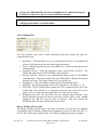
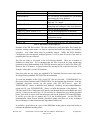
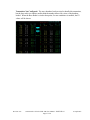
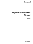
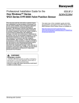
The connector for the SI-FTA is shown below. The ‘Data +’ and ‘Data –‘ connections for
the RS-485 wires are clearly marked on the body of the Field Termination Assembly. The
wiring for the RS-485 connection should be connected to be in the correct location.
Figure 1 - FTA Connector
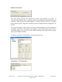
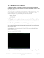
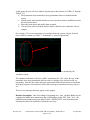
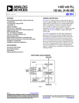
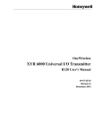
Shown below is the connection at the Base Radio. Note that a terminating resistor is shown
for the Modbus connection. If a terminating resistor is used, it must be applied at the
extreme ends (only 2 ends) of the RS-485 connection.
Figure 2 - Base Radio Connections
Revision 1.02
Serial Interface FTA for XYR 5000 User Manual - 34-XY-25-14
Page 9 of 91
30 April 2007
REQUIRED HARDWARE
•
•
•
•
TPS System with UCN containing at least one APM or HPM
Serial Interface IOP
Power Adaptor board
FTA (FTA is provided with the XYR Gateway package)
1
Serial Interface FTA for XYR
IM&C PART #
50018503,
50018511,
50018512, &
50018413
50018504
1
Power Adapter
50018505
1
5 /1 Meter FTA Cable (incl w/ SI-FTA)
1
IOP to FTA shield Cable
50018506 /
50018507
50018508
1
30 cm Serial Cable (incl w/ SI-FTA)
50018509
QTY
1
DESCRIPTION
Serial Interface IOP and XYR Firmware
A 2nd SI-FTA would also require another 51304465-100 cable.
If the SI-FTA is installed on an EPKS sytem, the parts list will differ.
Revision 1.02
Serial Interface FTA for XYR 5000 User Manual - 34-XY-25-14
Page 10 of 91
30 April 2007
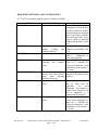
REQUIRED SOFTWARE AND LCN RESOURCES
A 2nd SI-FTA would also require another 51304465-100 cable.
NEED
REQUIRED
RESOURCE
GUS with File Transfer
REQUIRED
SI-IOP
Board,
Power
Adapter,
Cabling,
and
available xPM slot
Serial Array Points
REQUIRED
Numbers Required
One.
Without this, the
configurator will build files,
but there will be no method
for transferring the resultant
files to the History Module.
The configurator files can be
used as a guide to manually
building the database in this
case.
One SI-IOP and Power
Adapter set can handle 2 SIFTA
Minimum of 4. Refer to
Table 2 - Transmitter vs.
Array Requirements
1 per alarmable PV value.
There are 3 available PV
values per transmitter – most
transmitters do not utilize 3
PV values.
Maximum 7 – depending on
amount of flag/numeric data
required
DISCRETIONARY
Regulator PV points for
alarmable and scaleable
values
DISCRETIONARY
ProcMod
point(s)
for
moving flags and numeric
values
(non
alarming
numbers) from array
Flag Points for Transmitter Up to 9 flags per transmitter
Status
Not all flags may be
applicable
on
each
transmitter. For example, a
Square Root Function will
not be applicable to a
Temperature Transmitter.
Numeric Points for PV 1 per non-alarming / nonvalues
scaling value requiring a PV.
There are 3 available PV
values per transmitter – most
transmitters do not utilize 3
PV values.
DISCRETIONARY
DISCRETIONARY
Table 1 - Required Components
Revision 1.02
Serial Interface FTA for XYR 5000 User Manual - 34-XY-25-14
Page 11 of 91
30 April 2007
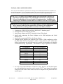
INSTALLATION OVERVIEW STEPS
These steps are not intended as a replacement for referring to the standard documentation for the xPM or for
the Wireless Base Radio. They are provided to guide the user in knowing which steps must be followed for
successful installation. It is presumed that the Wireless Base Radio is already configured properly.
NOTE: For TAC support of the implementation of the Discretionary features, the
Implementor must be familiar with APM/HPM Serial Interface configuration,
Process Point Building, & Process Module/CL Implementation. In addition, the
completed pre-installation checklist must be available to assist the TAC Engineer.
IMPORTANT: If you do not have a GUS station with File Transfer loaded, you will be
able to transfer neither the the supplied files (.DS and .DF) nor the Database
Configuration files (resulting from its execution) to the History Module.
1.
2.
3.
4.
Complete the “PRE-INSTALLATION CHECKLIST” found on page 2.
Install Serial Interface IOP into the xPM
Install Power Adapter and SI-FTA (typically in the xPM cabinet).
Install cable connecting the Power Adapter to the xPM backplane and Serial
Interface IOP.
5. Install cable connecting SI-FTA to the Power Adapter.
6. Configure Serial Interface IOP using the TDC system. While configuring, realize
the XYR 5000 SI-FTA will require a number array points to work. Ensure the
defined configuration has sufficient spare array points corresponding to the number
of transmitters being implemented. The number of arrays required is as follows:
# Transmitters
1-5
6-10
11-15
16-20
21-25
26-30
31-35
36-40
41-45
46-50
# SI Arrays Required
4
5
6
7
8
11
12
13
14
15
Table 2 - Transmitter vs. Array Requirements
7. As well, if an extended database of Numerics, Flags, RegPVs, and ProcMod points
are to be included so array data can be moved to ‘PV’ type points, the numbers
configured in the xPM for these items must also be adequate for the planned increase
in point types.
Revision 1.02
Serial Interface FTA for XYR 5000 User Manual - 34-XY-25-14
Page 12 of 91
30 April 2007
8. Connect the XYR 5000 Base Radio to the SI-FTA. This will require, as a minimum,
a connection using a twisted pair of wires. A 120 ohm resistor at each end of the
twisted pair may be required to allow proper communication using RS-485.
9. Use the XYR Database Configurator provided in this package to create the required
files for the points / database. It will be necessary to have some specific information
regarding the TDC system to properly build the database. Refer to the section in this
document labeled XYR DATABASE CONFIGURATOR for specific information.
10. If specific modifications are desired in the resultant .EB files, those changes should
be made at this point. These modifications may include ranges, limits, conversions,
point names, etc. Point names changed using the XYR Configurator will be
propogated throughout the resultant files.
11. If point names are manually changed in the .EB files created by the XYR
Configurator, the .CL files should be examined also for the original point names and
changed to match the new point names.
12. Move the files created by the XYR Database Configurator to the TDC History
Module using File Transfer or other appropriate means. If the File Transfer facility
is not available, the .EB files may be printed as templates for manual creation of files
or for manual entry of the database using the TDC 3000.
13. Run the .EC file XYRLDARR.EC. This will use the XYRDBARR.EC file and the
Array .EB file to build the required Array database.
14. If desired, run the .EC file XYRLDOTH.EC. This will use the XYRDBOTH.EC
file, the .EB files, and the .CL files to create the extended databases (RegPV,
Numeric, Flag, ProcMod), to compile the .CL required for the ProcMod points, and
to move the resultant CL object files to the appropriate location on the History
Module.
15. If ProcMod is used to move data from the Array database to other xPM points, the
CL for these points must be loaded and the CL started.
16. RegPV points will need to be set ‘ACTIVE’.
17. Using the TDC3000 Picture Editor, read in the XYR_DIAG schematic and the
XYRDDB display database. Use the ‘DEFINE INIT’ command to change the
database point names to those implemented on the TDC system. Compile the
schematic for diagnostic use.
Revision 1.02
Serial Interface FTA for XYR 5000 User Manual - 34-XY-25-14
Page 13 of 91
30 April 2007
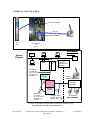
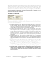
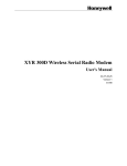
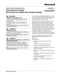
GENERAL LAYOUT DIAGRAM
51201420-005 / 50018506
RS-485
wires
51304465-100 / 50018509
SIIOP
System
Diagram
Power Supply
and
SI-FTA
GUS
HM
SI-IOP AND FTA
OVERVIEW:
US
LCN
UCN
A/HPM
Standard FTA
5 meters Cable
(up to 50 meters)
51201420-005 /
50018506
SI-IOP
MU-PSIM11
51304362-300 /
50018503
POWER
ADAPTER
Vendor
Subsystem(s)
XYR
SI-FTA
SI-FTA
11
MU-TSIM12
(Modbus RTU)
Field Devices or
Subsystems.
(Base Radio)
SI-FTA 2
(optional
51303932-???
)
Shielded Pair
30 cm Cable
(Up to 300 meters)
51304465-100 /
50018509
Serial Link Cables
EIA 232: Up to 15 m
EIA 485: Up to 300 m
To Remote RF
Sensor/Transmitters
Connection to the field devices can be made as either RS-232 or RS-485 (2-wire).
Wiring Diagram for TDC connection of SI-FTA
Revision 1.02
Serial Interface FTA for XYR 5000 User Manual - 34-XY-25-14
Page 14 of 91
30 April 2007
AVAILABLE BASE RADIO PARAMETERS
The Model XYR 5000 Base Radio provides parameters both for the base radio and for each
transmitter. The specific values can be found in the Wireless Base Radio Installation and
User’s Manual. The Base Radio has a set of values available that show information
regarding the transmitters in operation (see Table 3 - Base Transmitter Register Data). The
values for each individual transmitter consist of five (5) Floating Point values for each
transmitter (see Table 4 - Transmitter Modbus Addresses and Data). All values are mapped
into a simple format using data arrays for easy retrieval.
IMPORTANT NOTE: The XYR SI-FTA addresses the Base Radio in the REGMODE
format only.
BASE RADIO HOLDING REGISTERS
Register Address
0001
0002
0003
0004
0005
0006
0007
0008
0009
0010
Description
Device Type
Device Status
Number of Transmitters
Expected
Number of Transmitters
Communicating
Online/Offline Status of Field
Units 1-16
Online/Offline Status of Field
Units 17-32
Online/Offline Status of Field
Units 33-48
Online/Offline Status of Field
Units 49-50
Future Use
Future Use
Register / Data Type
16-bit Unsigned Integer
16-bit Unsigned Integer
16-bit Unsigned Integer
16-bit Unsigned Integer
16-bit Unsigned Integer
16-bit Unsigned Integer
16-bit Unsigned Integer
16-bit Unsigned Integer
16-bit Unsigned Integer
16-bit Unsigned Integer
Table 3 - Base Transmitter Register Data
The specific layouts and details of the data may be found in the XYR 5000 Wireless Base
Radio User Manual.
Revision 1.02
Serial Interface FTA for XYR 5000 User Manual - 34-XY-25-14
Page 15 of 91
30 April 2007
TRANSMITTER DATA TABLE
The data for the individual transmitters is stored in the Base Radio’s database using the
formula as shown in the following table.
Register Address
0001 (and 0002) + (RF ID *10)
0003 (and 0004) + (RF ID *10)
0005 (and 0006) + (RF ID *10)
0007 (and 0008) + (RF ID *10)
0009 (and 0010) + (RF ID *10)
Description
Device Type
Device Status
Primary Sensor Value
Secondary Sensor Value
Tertiary Sensor Value
Register Type
32 bit IEEE Floating Point
32 bit IEEE Floating Point
32 bit IEEE Floating Point
32 bit IEEE Floating Point
32 bit IEEE Floating Point
Table 4 - Transmitter Modbus Addresses and Data
The Device Types for the transmitters are stored into Array values associated with the XYR
SI-FTA (see Array_2_Table and Array_9_Table). The individual PV1, PV2, and PV3
Sensor Values are stored into Floating Point arrays (15 values per array) (see
Array_4_Table, etc.).
The Device Status is broken down into flags or discrete data for each individual sensor per
the breakout given in the XYR 5000 Wireless Base Radio User Manual (see Array_3_Table
and Array_10_Table).
The individual flags and the mnemonics used by default in the configuration are as follows:
• Onln – Online / Offline Status of the transmitter
• LBat – Low Battery
• Alrm – In Alarm
• SenE – Sensor Error
• ORng – Overrange condition in effect
• SysE – System Error
• S1Hi – Switch 1 is High
• S2Hi – Switch 2 is High
• SROn – Square Root Function in effect
• RSts – Future use
Revision 1.02
Serial Interface FTA for XYR 5000 User Manual - 34-XY-25-14
Page 16 of 91
30 April 2007
DATA BASE STRUCTURE
There are two main database portions involved with the XYR 5000 SI-FTA solution. First,
there is a base array database associated directly with the SI-FTA that maintains in it the values
read from the XYR 5000 Base Radio. Second, there is an ‘extended’ database where values can
be moved for scaling of PVs, alarming, logging, and for other functions. Without the array
database, there is no place to bring the values from the XYR 5000 into the TDC system. The
serial arrays as described herein are always required. The ‘extended’ database is always
optional. The TDC system will receive and be able to display XYR 5000 Base Radio data
without the ‘extended’ database. This section describes the two databases.
ARRAY DATABASE STRUCTURE
Data acquired from a connected device by the firmware residing on a SI FTA is mapped into
Array points. It is through this mapping that the data is communicated up through the SI
card to the system database associated with the SI-FTA. In this version of the XYR SIFTA, there are up to fifteen (15) array points of various types mapped into the FTA. The
XYR SI-FTA utilizing fifteen (15) Serial Interface arrays is enough to store data for the full
complement of transmitters available to an individual Base Radio.
The database configurator included with the XYR 5000 SI-FTA package will build files
(including .EB files, .EC files, and other necessary) for the required array database. The
configurator asks for a starting array slot and increments the arrays from that point. If the
system requires the 15 array point slots to be non-sequential, the slot locations can be easily
modified using either PC editing tools or the LCN Editor.
NOTE: Arrays must be built in the order shown below. If built out of order, the
interface will not function correctly.
NOTE: Arrays should be built with the full sizes shown below. Where insufficient
sizes are created, inconsistent data behavior may result.
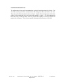
The first four (4) arrays are required with any implementation. They contain flag and
numeric data required for presentation of the transmitter data.
Array one (1) is a flag array of 151 elements that provides the user the ability to command
the XYR SI-FTA to convert the PV values 1 through 3 from DegC to DegF values (150
flags) and shows the Online status of the Base Radio (1 flag).
Array two (2) is a twenty seven (27) numeric array that reflects the Device Type of the first
twenty five (25) transmitters connected to the Base Radio plus the number of transmitters
expected by the base radio and the number of transmitters currently responding.
Revision 1.02
Serial Interface FTA for XYR 5000 User Manual - 34-XY-25-14
Page 17 of 91
30 April 2007
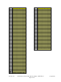
Array three (3) is a two hundred fifty (250) element flag array that contains the status flags
that are maintained by the Base Radio for the first twenty five (25) transmitters. There are
ten (10) flags per transmitter, with each successive ten(10) flags representing the next
transmitter.
Array four (4) is a 15 element array representing PV1, PV2, and PV3 of each of transmitters
one (1) through five (5).
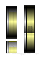
Array five (5), Array six (6), Array seven (7), and Array eight (8) represent the next sets of
transmitters, with each array allowing five (5) more transmitters.
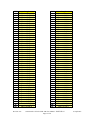
Array nine (9) is a twenty five (25) element array that reflects the Device Type of the
second twenty five (25) transmitters connected to the Base Radio.
Array ten (10) ) is a two hundred fifty (250) element flag array that contains the status flags
that are maintained by the Base Radio for the second twenty five (25) transmitters. There
are ten (10) flags per transmitter, with each successive ten(10) flags representing the next
transmitter.
Array eleven (11) is a 15 element array representing PV1, PV2, and PV3 of each of
transmitters twenty six (26) through thirty (30).
Array twelve (12), Array thirteen (13), Array fourteen (14), and Array fifteen (15) represent
the next sets of transmitters, with each array allowing five (5) more transmitters.
EXTENDED DATABASE STRUCTURE
All transmitter data obtained from the XYR 5000 is nominally placed into arrays associated
with the XYR 5000 SI-FTA. These values can be used in custom schematics and logs, but
where there is a need or a desire to alarm, scale, or simply to represent values as a .PV
rather than as an array element, additional points must be built that will receive the array
data. There are four basic point types that can be used in such a configuration. The
following table describes the point types and their usage.
POINT TYPE
FLAG
NUMERIC
Revision 1.02
USAGE
There are a fixed number of alarmable Flag points. Others are not
alarmable. The exact number depends on the PM type. An APM can
handle up to 128 alarmable flags. An HPM handles up to 1024
alarmable flags. All other flags are non-alarmable. The Flag point PV
is loaded by xPM Control Language (CL).
There are a fixed number of Numeric points. The number is the same
for both APM and HPM – 2047. Numeric points are non-alarmable
and non-scaleable. They are simply repositories for values. The
Numeric point PV is loaded by xPM CL.
Serial Interface FTA for XYR 5000 User Manual - 34-XY-25-14
Page 18 of 91
30 April 2007
POINT TYPE
REGPV
PROCMOD
USAGE
There are a fixed number of RegPV points. These are alarmable and
scaleable analog representations. The maximum number of RegPV
points for APM is 80. For HPM, the maximum number of RegPV
points is 125. The PV calculation may be selected by the user. There
are many RegPV algorithms that may be utilized and implemented to
meet the plant requirements. To keep things simple, the Database
Configurator builds only the Data Acquisition PV Algorithm. The PV
value for RegPV points will normally configured to be retrieved using
‘General Input’ points.
ProcMod points may number as high as 160 on the APM and up to
250 on the HPM. These points, when combined with CL, run
periodically to move the array data into the Flag and Numeric points.
If no flag or numeric points are required on the system, these types of
points can be omitted.
Table 5 - XYR Solution Point Types
A PC executable – XYR Database Configurator Tool – is provided with this package to help
prepare the TPS system arrays necessary for the SI-FTA to work properly. As well, the
package constructs .EB files and .CL as required for transferring data from arrays to nonarray points on the xPM. The Database Configurator presumes that slots increment
sequentially. If this is neither the case nor possible, the slot locations can be easily modified
using either PC editing tools or the LCN Editor.
An example of each extended point type and the associated xPM CL is provided within this
document.
Revision 1.02
Serial Interface FTA for XYR 5000 User Manual - 34-XY-25-14
Page 19 of 91
30 April 2007
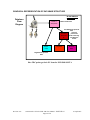
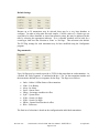
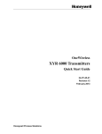
GRAPHICAL REPRESENTATION OF DATABASE STRUCTURE
SI-IOP AND FTA
OVERVIEW:
Database
Flow
Diagram
SI-FTA 1
Array Data
All data resides here
ProcMod Point pulls PV
data
and then
ProcMod
pushes the
Point and
data to the Flag
CL
and Numeric
Points
RegPV
Point
Flag Point
Numeric
Point
RegPV Point pulls PV
data
How TDC points get their PV from the XYR 5000 SI-FTA
Revision 1.02
Serial Interface FTA for XYR 5000 User Manual - 34-XY-25-14
Page 20 of 91
30 April 2007
DATA BASE UPDATE
Once the firmware receives the necessary configuration from the xPM, the XYR 5000 SIFTA builds its Modbus data request tables and begins to query the Base Radio for the
required parameter data. Once the Modbus data is read, parsing of the data takes place
through the data base starting with the first transmitter unit through the last transmitter unit.
All parameters for all transmitters are fetched before moving on.
If the number of transmitters configured (not the number responding, but the number
configured) is modified in the Base Radio, the data requested with the SI-FTA is
automatically adjusted accordingly.
As a Base Radio’s Modbus data table is requested, the returned data is inserted into the
appropriate locations in the SI-FTA data base.
Revision 1.02
Serial Interface FTA for XYR 5000 User Manual - 34-XY-25-14
Page 21 of 91
30 April 2007
REQUIRED DATABASE CONFIGURATION
The specific layout for all arrays associated with the FTA can be found in the section on
Database Organization. Proper configuration of the FTA slots is paramount to the correct
operation of the interface. It is very important that the FTA slots be configured correctly.
The following sections of the User Manual describe how each Array point is to be built.
The Database Configurator will build the base points and fill in the required information.
To inform the FTA of the slot type and other information concerning the interface, certain
parameters are used on the array point PED (parameter entry display). Some of the
parameters and their range of values are in the following table.
TDC3000 Param
DEVADDR
EPKS Param
DEVADDR
AUXDATA1
AUXDATA(0)
AUXDATA2
AUXDATA(1)
AUXDATA3
AUXDATA(2)
AUXDATA4
AUXDATA(3)
AB_Data1
AB_Data2
AUXDATA(4)
AUXDATA(5)
Revision 1.02
Function
Range
XYR 5000 Modbus Std Modbus ranges
Address
for a Modbus Device
Slot Number
Index Number (1-15)
based on:
“Table 7 - Size and
Configuration Table”
Message Time-out
0.25 – 3 seconds
(Array 1 only)
Link Type
For the XYR 5000,
485 (Array 1 only)
(see
APM/HPM
Serial
Interface
Options or EPKS
Serial
Interface
Module
Implementation
Guide
for
more
details)
BAUD Rate
1200 – 19200, with
the decimal indicating
parity (0 = none, 1 =
odd, 2 = even) (Array
1
only)
(see
APM/HPM
Serial
Interface Options or
EPKS Serial Interface
Module
Implementation
Guide
for
more
details)
Reserved
N/A
Reserved
N/A
Serial Interface FTA for XYR 5000 User Manual - 34-XY-25-14
Page 22 of 91
30 April 2007
TDC3000 Param
AB_Data3
EPKS Param
AUXDATA(6)
AB_Data4
AUXDATA(7)
SLOTNUM
Function
Master or Listener
Range
0 = Master; 1 =
Listener
(future)
(Array 1 only)
Version #
1 = Version 1; 2 =
Version 2 (future)
(Array 1 only)
Slot Number in the This must be unique
set of available xPM per SI Array point.
array points.
Table 6 - Parameter Entries for Array Points
Other than for the first Auxdata location, any data entered into the Aux parameters for
arrays 2-15 will be ignored.
Continue with the parameter configuration per the following table before saving the points.
INTERNAL
SLOT NUMBER
1
2
3
4
5
6
7
8
9
10
11
12
13
14
15
DATA TYPE
Flag / SIFLAGARRCH
Numeric / SINUMARRCH
Flag / SIFLAGARRCH
Numeric / SINUMARRCH
Numeric / SINUMARRCH
Numeric / SINUMARRCH
Numeric / SINUMARRCH
Numeric / SINUMARRCH
Numeric / SINUMARRCH
Flag / SIFLAGARRCH
Numeric / SINUMARRCH
Numeric / SINUMARRCH
Numeric / SINUMARRCH
Numeric / SINUMARRCH
Numeric / SINUMARRCH
AUXDATA1
INDEX
15
11
13
1
2
3
4
5
12
14
6
7
8
9
10
SIZE / # TO
CONFIGURE
151
27
250
15
15
15
15
15
25
250
15
15
15
15
15
Table 7 - Size and Configuration Table
Once all the required slot configurations are completed as described above, the FTA should
be scanning. Note that Slot/Array 1 will need configuration data that the other arrays will
not have to communicate properly.
If utilizing the interface on an EPKS system, when configuring the 2nd FTA, the 2nd set of
arrays require AUXDATA(0) to be as shown in Table 7 - Size and Configuration Table.
A PC executable – XYR Database Configurator Tool – is provided with this package to help
prepare the TPS system arrays necessary for the SI-FTA to work properly. As well, the
Revision 1.02
Serial Interface FTA for XYR 5000 User Manual - 34-XY-25-14
Page 23 of 91
30 April 2007
package constructs .EB files and .CL as required for transferring data from arrays to nonarray points on the xPM.
Revision 1.02
Serial Interface FTA for XYR 5000 User Manual - 34-XY-25-14
Page 24 of 91
30 April 2007
EXTENDED DATABASE CONFIGURATION
Nominally, all data from the Base Radio is stored into xPM array elements. If this is
adequate for your installation, then no other action is required.
However, if alarming, limit checking, or .PV parameter representation is desired or required,
a separate database must be built. There are a limited number of Regulatory PVs that can be
used for alarming, Numeric values that can be used to store values, Alarmable flags, and
non-alarmable flags. Consult the xPM manuals for details.
A PC executable – XYR Database Configurator Tool – is provided with this package to help
prepare the TPS system arrays necessary for the SI-FTA to work properly. As well, the
package constructs .EB files and .CL as required for transferring data from arrays to nonarray points on the xPM.
Revision 1.02
Serial Interface FTA for XYR 5000 User Manual - 34-XY-25-14
Page 25 of 91
30 April 2007
CONTROL CAPABILITIES
There are no control capabilities associated with the XYR 5000 Base Radio. It is treated as
a ‘read-only’ device.
Revision 1.02
Serial Interface FTA for XYR 5000 User Manual - 34-XY-25-14
Page 26 of 91
30 April 2007
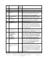
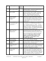
ERROR HANDLING
The interface firmware makes every attempt to detect and recover from communication
errors experienced on the serial link. Among these are no response from the connected
device, message framing errors, and parity errors. The SI ERROR field will display error
data. The errors are enumerated in the following table. The firmware will try a read
message a total of 3 times, waiting the configured message time-out time for a response
after each attempt. If there is no response an error is posted by the SI-FTA. Below is a list
of the error conditions detected and posted by the FTA. All errors are listed – some may not
be applicable to this specific application.
SI ERROR AND COMMUNICATION ERROR ARRAY Indications:
TDC Notation
NO CONF
DEV ADDR
DATATYPE
STARTIDX
# ELEMNT
TMOT VAL
AUXMATCH
EX SIG/MOD
BAUD/PAR
CONFIG
CHECKSUM
DEBUG ER
MAX CONF
INV RESP
PARITY
MSGTMOUT
UNIT CNF
RX OVFLO
XMR EXCD
ARRORDER
OK
Indication
No Configuration
Device Address has a configuration error
Data Type has a configuration error
Start Index has a configuration error
Number of Elements Error. The arrays must have the
number of elements as described herein.
Illegal Message Timeout Time
Signal/Modem Mismatch error
Exception or other Field generated error
Illegal Signal/Modem value.
Illegal Baud/Parity value.
Generic Configuration Error
Checksum Error
Special debug error codes used in Factory Test
Maximum Configuration Error
Invalid Response in the Receive Buffer
Parity Error
Message Time-out Error (no response)
Unit Not Configured
Receive Buffer Overflow
Number of transmitters exceeded.
Arrays built out of order. Arrays must be built in order.
No Problems
Table 8 - Error Indications
Revision 1.02
Serial Interface FTA for XYR 5000 User Manual - 34-XY-25-14
Page 27 of 91
30 April 2007
SYSTEM PERFORMANCE
The performance of any serial communications system is based upon some key factors. The
first is the actual speed of the communications link being used, the actual time on the wire.
This value is fixed based on the baud rate selected. Another factor of importance is the time
it takes for the connected device to decode and respond to a query. It is also important to
know how long it takes the host device to process the response it receives and then to
generate the next query. These factors together determine the performance of the link.
Revision 1.02
Serial Interface FTA for XYR 5000 User Manual - 34-XY-25-14
Page 28 of 91
30 April 2007
XYR 5000 BASE RADIO
SI-FTA ARRAY
DATA BASE ORGANIZATION
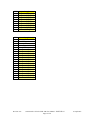
ARRAYS REQUIRED FOR UP TO 5
TRANSMITTERS
LOC
1
2
3
4
5
6
7
8
9
10
11
12
13
14
15
16
17
18
19
20
21
22
23
24
25
26
27
28
29
30
31
32
33
Array 1
ID 15
1-5 Transmitters
Conversion Flags
Trans 1-50
151 Flags
Trans.1 Conversion Flag 1
Trans.1 Conversion Flag 2
Trans.1 Conversion Flag 3
Trans.2 Conversion Flag 1
Trans.2 Conversion Flag 2
Trans.2 Conversion Flag 3
Trans.3 Conversion Flag 1
Trans.3 Conversion Flag 2
Trans.3 Conversion Flag 3
Trans.4 Conversion Flag 1
Trans.4 Conversion Flag 2
Trans.4 Conversion Flag 3
Trans.5 Conversion Flag 1
Trans.5 Conversion Flag 2
Trans.5 Conversion Flag 3
Trans.6 Conversion Flag 1
Trans.6 Conversion Flag 2
Trans.6 Conversion Flag 3
Trans.7 Conversion Flag 1
Trans.7 Conversion Flag 2
Trans.7 Conversion Flag 3
Trans.8 Conversion Flag 1
Trans.8 Conversion Flag 2
Trans.8 Conversion Flag 3
Trans.9 Conversion Flag 1
Trans.9 Conversion Flag 2
Trans.9 Conversion Flag 3
Trans.10 Conversion Flag 1
Trans.10 Conversion Flag 2
Trans.10 Conversion Flag 3
Trans.11 Conversion Flag 1
Trans.11 Conversion Flag 2
Trans.11 Conversion Flag 3
Revision 1.02
LOC
34
35
36
37
38
39
40
41
42
43
44
45
46
47
48
49
50
51
52
53
54
55
56
57
58
59
60
61
62
63
64
65
66
67
68
69
70
71
72
73
74
Array 1
Trans.12 Conversion Flag 1
Trans.12 Conversion Flag 2
Trans.12 Conversion Flag 3
Trans.13 Conversion Flag 1
Trans.13 Conversion Flag 2
Trans.13 Conversion Flag 3
Trans.14 Conversion Flag 1
Trans.14 Conversion Flag 2
Trans.14 Conversion Flag 3
Trans.15 Conversion Flag 1
Trans.15 Conversion Flag 2
Trans.15 Conversion Flag 3
Trans.16 Conversion Flag 1
Trans.16 Conversion Flag 2
Trans.16 Conversion Flag 3
Trans.17 Conversion Flag 1
Trans.17 Conversion Flag 2
Trans.17 Conversion Flag 3
Trans.18 Conversion Flag 1
Trans.18 Conversion Flag 2
Trans.18 Conversion Flag 3
Trans.19 Conversion Flag 1
Trans.19 Conversion Flag 2
Trans.19 Conversion Flag 3
Trans.20 Conversion Flag 1
Trans.20 Conversion Flag 2
Trans.20 Conversion Flag 3
Trans.21 Conversion Flag 1
Trans.21 Conversion Flag 2
Trans.21 Conversion Flag 3
Trans.22 Conversion Flag 1
Trans.22 Conversion Flag 2
Trans.22 Conversion Flag 3
Trans.23 Conversion Flag 1
Trans.23 Conversion Flag 2
Trans.23 Conversion Flag 3
Trans.24 Conversion Flag 1
Trans.24 Conversion Flag 2
Trans.24 Conversion Flag 3
Trans.25 Conversion Flag 1
Trans.25 Conversion Flag 2
Serial Interface FTA for XYR 5000 User Manual - 34-XY-25-14
Page 29 of 91
30 April 2007
LOC
75
76
77
78
79
80
81
82
83
84
85
86
87
88
89
90
91
92
93
94
95
96
97
98
99
100
101
102
103
104
105
106
107
108
109
110
111
112
113
114
115
116
117
118
119
120
121
Array 1
Trans.25 Conversion Flag 3
Trans.26 Conversion Flag 1
Trans.26 Conversion Flag 2
Trans.26 Conversion Flag 3
Trans.27 Conversion Flag 1
Trans.27 Conversion Flag 2
Trans.27 Conversion Flag 3
Trans.28 Conversion Flag 1
Trans.28 Conversion Flag 2
Trans.28 Conversion Flag 3
Trans.29 Conversion Flag 1
Trans.29 Conversion Flag 2
Trans.29 Conversion Flag 3
Trans.30 Conversion Flag 1
Trans.30 Conversion Flag 2
Trans.30 Conversion Flag 3
Trans.31 Conversion Flag 1
Trans.31 Conversion Flag 2
Trans.31 Conversion Flag 3
Trans.32 Conversion Flag 1
Trans.32 Conversion Flag 2
Trans.32 Conversion Flag 3
Trans.33 Conversion Flag 1
Trans.33 Conversion Flag 2
Trans.33 Conversion Flag 3
Trans.34 Conversion Flag 1
Trans.34 Conversion Flag 2
Trans.34 Conversion Flag 3
Trans.35 Conversion Flag 1
Trans.35 Conversion Flag 2
Trans.35 Conversion Flag 3
Trans.36 Conversion Flag 1
Trans.36 Conversion Flag 2
Trans.36 Conversion Flag 3
Trans.37 Conversion Flag 1
Trans.37 Conversion Flag 2
Trans.37 Conversion Flag 3
Trans.38 Conversion Flag 1
Trans.38 Conversion Flag 2
Trans.38 Conversion Flag 3
Trans.39 Conversion Flag 1
Trans.39 Conversion Flag 2
Trans.39 Conversion Flag 3
Trans.40 Conversion Flag 1
Trans.40 Conversion Flag 2
Trans.40 Conversion Flag 3
Trans.41 Conversion Flag 1
Revision 1.02
LOC
122
123
124
125
126
127
128
129
130
131
132
133
134
135
136
137
138
139
140
141
142
143
144
145
146
147
148
149
150
151
Array 1
Trans.41 Conversion Flag 2
Trans.41 Conversion Flag 3
Trans.42 Conversion Flag 1
Trans.42 Conversion Flag 2
Trans.42 Conversion Flag 3
Trans.43 Conversion Flag 1
Trans.43 Conversion Flag 2
Trans.43 Conversion Flag 3
Trans.44 Conversion Flag 1
Trans.44 Conversion Flag 2
Trans.44 Conversion Flag 3
Trans.45 Conversion Flag 1
Trans.45 Conversion Flag 2
Trans.45 Conversion Flag 3
Trans.46 Conversion Flag 1
Trans.46 Conversion Flag 2
Trans.46 Conversion Flag 3
Trans.47 Conversion Flag 1
Trans.47 Conversion Flag 2
Trans.47 Conversion Flag 3
Trans.48 Conversion Flag 1
Trans.48 Conversion Flag 2
Trans.48 Conversion Flag 3
Trans.49 Conversion Flag 1
Trans.49 Conversion Flag 2
Trans.49 Conversion Flag 3
Trans.50 Conversion Flag 1
Trans.50 Conversion Flag 2
Trans.50 Conversion Flag 3
Base Online
Serial Interface FTA for XYR 5000 User Manual - 34-XY-25-14
Page 30 of 91
30 April 2007
LOC
1
2
3
4
5
6
7
8
9
10
11
12
13
14
15
16
17
18
19
20
21
22
23
24
25
26
27
LOC
1
2
3
4
5
6
Array 2
ID 11
1-5 Transmitters
Trans Types
Trans 1-25
27 Values
Trans. 1 Type
Trans. 2 Type
Trans. 3 Type
Trans. 4 Type
Trans. 5 Type
Trans. 6 Type
Trans. 7 Type
Trans. 8 Type
Trans. 9 Type
Trans. 10 Type
Trans. 11 Type
Trans. 12 Type
Trans. 13 Type
Trans. 14 Type
Trans. 15 Type
Trans. 16 Type
Trans. 17 Type
Trans. 18 Type
Trans. 19 Type
Trans. 20 Type
Trans. 21 Type
Trans. 22 Type
Trans. 23 Type
Trans. 24 Type
Trans. 25 Type
# Trans. Configured
# Trans. Responding
Array 3
ID 13
1-5 Transmitters
Trans Flags
Trans 1-25
250 Flags
Trans. 1 Flag 1
Trans. 1 Flag 2
Trans. 1 Flag 3
Trans. 1 Flag 4
Trans. 1 Flag 5
Trans. 1 Flag 6
Revision 1.02
LOC
7
8
9
10
11
12
13
14
15
16
17
18
19
20
21
22
23
24
25
26
27
28
29
30
31
32
33
34
35
36
37
38
39
40
41
42
43
44
45
46
47
48
49
50
51
52
53
Array 3
Trans. 1 Flag 7
Trans. 1 Flag 8
Trans. 1 Flag 9
Trans. 1 Flag 10
Trans. 2 Flag 1
Trans. 2 Flag 2
Trans. 2 Flag 3
Trans. 2 Flag 4
Trans. 2 Flag 5
Trans. 2 Flag 6
Trans. 2 Flag 7
Trans. 2 Flag 8
Trans. 2 Flag 9
Trans. 2 Flag 10
Trans. 3 Flag 1
Trans. 3 Flag 2
Trans. 3 Flag 3
Trans. 3 Flag 4
Trans. 3 Flag 5
Trans. 3 Flag 6
Trans. 3 Flag 7
Trans. 3 Flag 8
Trans. 3 Flag 9
Trans. 3 Flag 10
Trans. 4 Flag 1
Trans. 4 Flag 2
Trans. 4 Flag 3
Trans. 4 Flag 4
Trans. 4 Flag 5
Trans. 4 Flag 6
Trans. 4 Flag 7
Trans. 4 Flag 8
Trans. 4 Flag 9
Trans. 4 Flag 10
Trans. 5 Flag 1
Trans. 5 Flag 2
Trans. 5 Flag 3
Trans. 5 Flag 4
Trans. 5 Flag 5
Trans. 5 Flag 6
Trans. 5 Flag 7
Trans. 5 Flag 8
Trans. 5 Flag 9
Trans. 5 Flag 10
Trans. 6 Flag 1
Trans. 6 Flag 2
Trans. 6 Flag 3
Serial Interface FTA for XYR 5000 User Manual - 34-XY-25-14
Page 31 of 91
30 April 2007
LOC
54
55
56
57
58
59
60
61
62
63
64
65
66
67
68
69
70
71
72
73
74
75
76
77
78
79
80
81
82
83
84
85
86
87
88
89
90
91
92
93
94
95
96
97
98
99
100
Array 3
Trans. 6 Flag 4
Trans. 6 Flag 5
Trans. 6 Flag 6
Trans. 6 Flag 7
Trans. 6 Flag 8
Trans. 6 Flag 9
Trans. 6 Flag 10
Trans. 7 Flag 1
Trans. 7 Flag 2
Trans. 7 Flag 3
Trans. 7 Flag 4
Trans. 7 Flag 5
Trans. 7 Flag 6
Trans. 7 Flag 7
Trans. 7 Flag 8
Trans. 7 Flag 9
Trans. 7 Flag 10
Trans. 8 Flag 1
Trans. 8 Flag 2
Trans. 8 Flag 3
Trans. 8 Flag 4
Trans. 8 Flag 5
Trans. 8 Flag 6
Trans. 8 Flag 7
Trans. 8 Flag 8
Trans. 8 Flag 9
Trans. 8 Flag 10
Trans. 9 Flag 1
Trans. 9 Flag 2
Trans. 9 Flag 3
Trans. 9 Flag 4
Trans. 9 Flag 5
Trans. 9 Flag 6
Trans. 9 Flag 7
Trans. 9 Flag 8
Trans. 9 Flag 9
Trans. 9 Flag 10
Trans. 10 Flag 1
Trans. 10 Flag 2
Trans. 10 Flag 3
Trans. 10 Flag 4
Trans. 10 Flag 5
Trans. 10 Flag 6
Trans. 10 Flag 7
Trans. 10 Flag 8
Trans. 10 Flag 9
Trans. 10 Flag 10
Revision 1.02
LOC
101
102
103
104
105
106
107
108
109
110
111
112
113
114
115
116
117
118
119
120
121
122
123
124
125
126
127
128
129
130
131
132
133
134
135
136
137
138
139
140
141
142
143
144
145
146
147
Array 3
Trans. 11 Flag 1
Trans. 11 Flag 2
Trans. 11 Flag 3
Trans. 11 Flag 4
Trans. 11 Flag 5
Trans. 11 Flag 6
Trans. 11 Flag 7
Trans. 11 Flag 8
Trans. 11 Flag 9
Trans. 11 Flag 10
Trans. 12 Flag 1
Trans. 12 Flag 2
Trans. 12 Flag 3
Trans. 12 Flag 4
Trans. 12 Flag 5
Trans. 12 Flag 6
Trans. 12 Flag 7
Trans. 12 Flag 8
Trans. 12 Flag 9
Trans. 12 Flag 10
Trans. 13 Flag 1
Trans. 13 Flag 2
Trans. 13 Flag 3
Trans. 13 Flag 4
Trans. 13 Flag 5
Trans. 13 Flag 6
Trans. 13 Flag 7
Trans. 13 Flag 8
Trans. 13 Flag 9
Trans. 13 Flag 10
Trans. 14 Flag 1
Trans. 14 Flag 2
Trans. 14 Flag 3
Trans. 14 Flag 4
Trans. 14 Flag 5
Trans. 14 Flag 6
Trans. 14 Flag 7
Trans. 14 Flag 8
Trans. 14 Flag 9
Trans. 14 Flag 10
Trans. 15 Flag 1
Trans. 15 Flag 2
Trans. 15 Flag 3
Trans. 15 Flag 4
Trans. 15 Flag 5
Trans. 15 Flag 6
Trans. 15 Flag 7
Serial Interface FTA for XYR 5000 User Manual - 34-XY-25-14
Page 32 of 91
30 April 2007
LOC
148
149
150
151
152
153
154
155
156
157
158
159
160
161
162
163
164
165
166
167
168
169
170
171
172
173
174
175
176
177
178
179
180
181
182
183
184
185
186
187
188
189
190
191
192
193
194
Array 3
Trans. 15 Flag 8
Trans. 15 Flag 9
Trans. 15 Flag 10
Trans. 16 Flag 1
Trans. 16 Flag 2
Trans. 16 Flag 3
Trans. 16 Flag 4
Trans. 16 Flag 5
Trans. 16 Flag 6
Trans. 16 Flag 7
Trans. 16 Flag 8
Trans. 16 Flag 9
Trans. 16 Flag 10
Trans. 17 Flag 1
Trans. 17 Flag 2
Trans. 17 Flag 3
Trans. 17 Flag 4
Trans. 17 Flag 5
Trans. 17 Flag 6
Trans. 17 Flag 7
Trans. 17 Flag 8
Trans. 17 Flag 9
Trans. 17 Flag 10
Trans. 18 Flag 1
Trans. 18 Flag 2
Trans. 18 Flag 3
Trans. 18 Flag 4
Trans. 18 Flag 5
Trans. 18 Flag 6
Trans. 18 Flag 7
Trans. 18 Flag 8
Trans. 18 Flag 9
Trans. 18 Flag 10
Trans. 19 Flag 1
Trans. 19 Flag 2
Trans. 19 Flag 3
Trans. 19 Flag 4
Trans. 19 Flag 5
Trans. 19 Flag 6
Trans. 19 Flag 7
Trans. 19 Flag 8
Trans. 19 Flag 9
Trans. 19 Flag 10
Trans. 20 Flag 1
Trans. 20 Flag 2
Trans. 20 Flag 3
Trans. 20 Flag 4
Revision 1.02
LOC
195
196
197
198
199
200
201
202
203
204
205
206
207
208
209
210
211
212
213
214
215
216
217
218
219
220
221
222
223
224
225
226
227
228
229
230
231
232
233
234
235
236
237
238
239
240
241
Array 3
Trans. 20 Flag 5
Trans. 20 Flag 6
Trans. 20 Flag 7
Trans. 20 Flag 8
Trans. 20 Flag 9
Trans. 20 Flag 10
Trans. 21 Flag 1
Trans. 21 Flag 2
Trans. 21 Flag 3
Trans. 21 Flag 4
Trans. 21 Flag 5
Trans. 21 Flag 6
Trans. 21 Flag 7
Trans. 21 Flag 8
Trans. 21 Flag 9
Trans. 21 Flag 10
Trans. 22 Flag 1
Trans. 22 Flag 2
Trans. 22 Flag 3
Trans. 22 Flag 4
Trans. 22 Flag 5
Trans. 22 Flag 6
Trans. 22 Flag 7
Trans. 22 Flag 8
Trans. 22 Flag 9
Trans. 22 Flag 10
Trans. 23 Flag 1
Trans. 23 Flag 2
Trans. 23 Flag 3
Trans. 23 Flag 4
Trans. 23 Flag 5
Trans. 23 Flag 6
Trans. 23 Flag 7
Trans. 23 Flag 8
Trans. 23 Flag 9
Trans. 23 Flag 10
Trans. 24 Flag 1
Trans. 24 Flag 2
Trans. 24 Flag 3
Trans. 24 Flag 4
Trans. 24 Flag 5
Trans. 24 Flag 6
Trans. 24 Flag 7
Trans. 24 Flag 8
Trans. 24 Flag 9
Trans. 24 Flag 10
Trans. 25 Flag 1
Serial Interface FTA for XYR 5000 User Manual - 34-XY-25-14
Page 33 of 91
30 April 2007
LOC
242
243
244
245
246
247
248
249
250
Array 3
Trans. 25 Flag 2
Trans. 25 Flag 3
Trans. 25 Flag 4
Trans. 25 Flag 5
Trans. 25 Flag 6
Trans. 25 Flag 7
Trans. 25 Flag 8
Trans. 25 Flag 9
Trans. 25 Flag 10
LOC
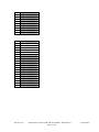
Array 4
ID 1
1-5 Transmitters
PVs
Trans 1-5
15 FP Values
Trans. 1 PV 1
Trans. 1 PV 2
Trans. 1 PV 3
Trans. 2 PV 1
Trans. 2 PV 2
Trans. 2 PV 3
Trans. 3 PV 1
Trans. 3 PV 2
Trans. 3 PV 3
Trans. 4 PV 1
Trans. 4 PV 2
Trans. 4 PV 3
Trans. 5 PV 1
Trans. 5 PV 2
Trans. 5 PV 3
1
2
3
4
5
6
7
8
9
10
11
12
13
14
15
Revision 1.02
Serial Interface FTA for XYR 5000 User Manual - 34-XY-25-14
Page 34 of 91
30 April 2007
ADDITIONAL ARRAYS REQUIRED FOR UP
TO 25 TRANSMITTERS
LOC
1
2
3
4
5
6
7
8
9
10
11
12
13
14
15
LOC
1
2
3
4
5
6
7
8
9
10
11
12
13
14
15
Array 5
ID 2
6-10 Transmitterse
PVs
Trans 6-10
15 FP Values
Trans. 6 PV 1
Trans. 6 PV 2
Trans. 6 PV 3
Trans. 7 PV 1
Trans. 7 PV 2
Trans. 7 PV 3
Trans. 8 PV 1
Trans. 8 PV 2
Trans. 8 PV 3
Trans. 9 PV 1
Trans. 9 PV 2
Trans. 9 PV 3
Trans. 10 PV 1
Trans. 10 PV 2
Trans. 10 PV 3
LOC
Array 6
ID 3
11-15 Transmitters
PVs
Trans 11-15
15 FP Values
Trans. 11 PV 1
Trans. 11 PV 2
Trans. 11 PV 3
Trans. 12 PV 1
Trans. 12 PV 2
Trans. 12 PV 3
Trans. 13 PV 1
Trans. 13 PV 2
Trans. 13 PV 3
Trans. 14 PV 1
Trans. 14 PV 2
Trans. 14 PV 3
Trans. 15 PV 1
Trans. 15 PV 2
Trans. 15 PV 3
LOC
Revision 1.02
1
2
3
4
5
6
7
8
9
10
11
12
13
14
15
1
2
3
4
5
6
7
8
9
10
11
12
13
14
15
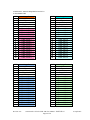
Array 7
ID 4
16-20 Transmitters
PVs
Trans 16-20
15 FP Values
Trans. 16 PV 1
Trans. 16 PV 2
Trans. 16 PV 3
Trans. 17 PV 1
Trans. 17 PV 2
Trans. 17 PV 3
Trans. 18 PV 1
Trans. 18 PV 2
Trans. 18 PV 3
Trans. 19 PV 1
Trans. 19 PV 2
Trans. 19 PV 3
Trans. 20 PV 1
Trans. 20 PV 2
Trans. 20 PV 3
Array 8
ID 5
21-25 Transmitters
PVs
Trans 21-25
15 FP Values
Trans. 21 PV 1
Trans. 21 PV 2
Trans. 21 PV 3
Trans. 22 PV 1
Trans. 22 PV 2
Trans. 22 PV 3
Trans. 23 PV 1
Trans. 23 PV 2
Trans. 23 PV 3
Trans. 24 PV 1
Trans. 24 PV 2
Trans. 24 PV 3
Trans. 25 PV 1
Trans. 25 PV 2
Trans. 25 PV 3
Serial Interface FTA for XYR 5000 User Manual - 34-XY-25-14
Page 35 of 91
30 April 2007
ADDITIONAL ARRAYS REQUIRED FOR UP TO
30 TRANSMITTERS
LOC
1
2
3
4
5
6
7
8
9
10
11
12
13
14
15
16
17
18
19
20
21
22
23
24
25
LOC
1
2
3
4
5
6
Array 9
ID 12
26-30 Transmitters
Trans Types
Trans 26-50
25 Values
Trans. 26 Type
Trans. 27 Type
Trans. 28 Type
Trans. 29 Type
Trans. 30 Type
Trans. 31 Type
Trans. 32 Type
Trans. 33 Type
Trans. 34 Type
Trans. 35 Type
Trans. 36 Type
Trans. 37 Type
Trans. 38 Type
Trans. 39 Type
Trans. 40 Type
Trans. 41 Type
Trans. 42 Type
Trans. 43 Type
Trans. 44 Type
Trans. 45 Type
Trans. 46 Type
Trans. 47 Type
Trans. 48 Type
Trans. 49 Type
Trans. 50 Type
Array 10
ID 14
26-30 Transmitters
Trans Flags
Trans 26-50
250 Flags
Trans. 26 Flag 1
Trans. 26 Flag 2
Trans. 26 Flag 3
Trans. 26 Flag 4
Trans. 26 Flag 5
Trans. 26 Flag 6
Revision 1.02
LOC
7
8
9
10
11
12
13
14
15
16
17
18
19
20
21
22
23
24
25
26
27
28
29
30
31
32
33
34
35
36
37
38
39
40
41
42
43
44
45
46
47
48
49
50
51
52
53
Array 10
Trans. 26 Flag 7
Trans. 26 Flag 8
Trans. 26 Flag 9
Trans. 26 Flag 10
Trans. 27 Flag 1
Trans. 27 Flag 2
Trans. 27 Flag 3
Trans. 27 Flag 4
Trans. 27 Flag 5
Trans. 27 Flag 6
Trans. 27 Flag 7
Trans. 27 Flag 8
Trans. 27 Flag 9
Trans. 27 Flag 10
Trans. 28 Flag 1
Trans. 28 Flag 2
Trans. 28 Flag 3
Trans. 28 Flag 4
Trans. 28 Flag 5
Trans. 28 Flag 6
Trans. 28 Flag 7
Trans. 28 Flag 8
Trans. 28 Flag 9
Trans. 28 Flag 10
Trans. 29 Flag 1
Trans. 29 Flag 2
Trans. 29 Flag 3
Trans. 29 Flag 4
Trans. 29 Flag 5
Trans. 29 Flag 6
Trans. 29 Flag 7
Trans. 29 Flag 8
Trans. 29 Flag 9
Trans. 29 Flag 10
Trans. 30 Flag 1
Trans. 30 Flag 2
Trans. 30 Flag 3
Trans. 30 Flag 4
Trans. 30 Flag 5
Trans. 30 Flag 6
Trans. 30 Flag 7
Trans. 30 Flag 8
Trans. 30 Flag 9
Trans. 30 Flag 10
Trans. 31 Flag 1
Trans. 31 Flag 2
Trans. 31 Flag 3
Serial Interface FTA for XYR 5000 User Manual - 34-XY-25-14
Page 36 of 91
30 April 2007
LOC
54
55
56
57
58
59
60
61
62
63
64
65
66
67
68
69
70
71
72
73
74
75
76
77
78
79
80
81
82
83
84
85
86
87
88
89
90
91
92
93
94
95
96
97
98
99
100
Array 10
Trans. 31 Flag 4
Trans. 31 Flag 5
Trans. 31 Flag 6
Trans. 31 Flag 7
Trans. 31 Flag 8
Trans. 31 Flag 9
Trans. 31 Flag 10
Trans. 32 Flag 1
Trans. 32 Flag 2
Trans. 32 Flag 3
Trans. 32 Flag 4
Trans. 32 Flag 5
Trans. 32 Flag 6
Trans. 32 Flag 7
Trans. 32 Flag 8
Trans. 32 Flag 9
Trans. 32 Flag 10
Trans. 33 Flag 1
Trans. 33 Flag 2
Trans. 33 Flag 3
Trans. 33 Flag 4
Trans. 33 Flag 5
Trans. 33 Flag 6
Trans. 33 Flag 7
Trans. 33 Flag 8
Trans. 33 Flag 9
Trans. 33 Flag 10
Trans. 34 Flag 1
Trans. 34 Flag 2
Trans. 34 Flag 3
Trans. 34 Flag 4
Trans. 34 Flag 5
Trans. 34 Flag 6
Trans. 34 Flag 7
Trans. 34 Flag 8
Trans. 34 Flag 9
Trans. 34 Flag 10
Trans. 35 Flag 1
Trans. 35 Flag 2
Trans. 35 Flag 3
Trans. 35 Flag 4
Trans. 35 Flag 5
Trans. 35 Flag 6
Trans. 35 Flag 7
Trans. 35 Flag 8
Trans. 35 Flag 9
Trans. 35 Flag 10
Revision 1.02
LOC
101
102
103
104
105
106
107
108
109
110
111
112
113
114
115
116
117
118
119
120
121
122
123
124
125
126
127
128
129
130
131
132
133
134
135
136
137
138
139
140
141
142
143
144
145
146
147
Array 10
Trans. 36 Flag 1
Trans. 36 Flag 2
Trans. 36 Flag 3
Trans. 36 Flag 4
Trans. 36 Flag 5
Trans. 36 Flag 6
Trans. 36 Flag 7
Trans. 36 Flag 8
Trans. 36 Flag 9
Trans. 36 Flag 10
Trans. 37 Flag 1
Trans. 37 Flag 2
Trans. 37 Flag 3
Trans. 37 Flag 4
Trans. 37 Flag 5
Trans. 37 Flag 6
Trans. 37 Flag 7
Trans. 37 Flag 8
Trans. 37 Flag 9
Trans. 37 Flag 10
Trans. 38 Flag 1
Trans. 38 Flag 2
Trans. 38 Flag 3
Trans. 38 Flag 4
Trans. 38 Flag 5
Trans. 38 Flag 6
Trans. 38 Flag 7
Trans. 38 Flag 8
Trans. 38 Flag 9
Trans. 38 Flag 10
Trans. 39 Flag 1
Trans. 39 Flag 2
Trans. 39 Flag 3
Trans. 39 Flag 4
Trans. 39 Flag 5
Trans. 39 Flag 6
Trans. 39 Flag 7
Trans. 39 Flag 8
Trans. 39 Flag 9
Trans. 39 Flag 10
Trans. 40 Flag 1
Trans. 40 Flag 2
Trans. 40 Flag 3
Trans. 40 Flag 4
Trans. 40 Flag 5
Trans. 40 Flag 6
Trans. 40 Flag 7
Serial Interface FTA for XYR 5000 User Manual - 34-XY-25-14
Page 37 of 91
30 April 2007
LOC
148
149
150
151
152
153
154
155
156
157
158
159
160
161
162
163
164
165
166
167
168
169
170
171
172
173
174
175
176
177
178
179
180
181
182
183
184
185
186
187
188
189
190
191
192
193
194
Array 10
Trans. 40 Flag 8
Trans. 40 Flag 9
Trans. 40 Flag 10
Trans. 41 Flag 1
Trans. 41 Flag 2
Trans. 41 Flag 3
Trans. 41 Flag 4
Trans. 41 Flag 5
Trans. 41 Flag 6
Trans. 41 Flag 7
Trans. 41 Flag 8
Trans. 41 Flag 9
Trans. 41 Flag 10
Trans. 42 Flag 1
Trans. 42 Flag 2
Trans. 42 Flag 3
Trans. 42 Flag 4
Trans. 42 Flag 5
Trans. 42 Flag 6
Trans. 42 Flag 7
Trans. 42 Flag 8
Trans. 42 Flag 9
Trans. 42 Flag 10
Trans. 43 Flag 1
Trans. 43 Flag 2
Trans. 43 Flag 3
Trans. 43 Flag 4
Trans. 43 Flag 5
Trans. 43 Flag 6
Trans. 43 Flag 7
Trans. 43 Flag 8
Trans. 43 Flag 9
Trans. 43 Flag 10
Trans. 44 Flag 1
Trans. 44 Flag 2
Trans. 44 Flag 3
Trans. 44 Flag 4
Trans. 44 Flag 5
Trans. 44 Flag 6
Trans. 44 Flag 7
Trans. 44 Flag 8
Trans. 44 Flag 9
Trans. 44 Flag 10
Trans. 45 Flag 1
Trans. 45 Flag 2
Trans. 45 Flag 3
Trans. 45 Flag 4
Revision 1.02
LOC
195
196
197
198
199
200
201
202
203
204
205
206
207
208
209
210
211
212
213
214
215
216
217
218
219
220
221
222
223
224
225
226
227
228
229
230
231
232
233
234
235
236
237
238
239
240
241
Array 10
Trans. 45 Flag 5
Trans. 45 Flag 6
Trans. 45 Flag 7
Trans. 45 Flag 8
Trans. 45 Flag 9
Trans. 45 Flag 10
Trans. 46 Flag 1
Trans. 46 Flag 2
Trans. 46 Flag 3
Trans. 46 Flag 4
Trans. 46 Flag 5
Trans. 46 Flag 6
Trans. 46 Flag 7
Trans. 46 Flag 8
Trans. 46 Flag 9
Trans. 46 Flag 10
Trans. 47 Flag 1
Trans. 47 Flag 2
Trans. 47 Flag 3
Trans. 47 Flag 4
Trans. 47 Flag 5
Trans. 47 Flag 6
Trans. 47 Flag 7
Trans. 47 Flag 8
Trans. 47 Flag 9
Trans. 47 Flag 10
Trans. 48 Flag 1
Trans. 48 Flag 2
Trans. 48 Flag 3
Trans. 48 Flag 4
Trans. 48 Flag 5
Trans. 48 Flag 6
Trans. 48 Flag 7
Trans. 48 Flag 8
Trans. 48 Flag 9
Trans. 48 Flag 10
Trans. 49 Flag 1
Trans. 49 Flag 2
Trans. 49 Flag 3
Trans. 49 Flag 4
Trans. 49 Flag 5
Trans. 49 Flag 6
Trans. 49 Flag 7
Trans. 49 Flag 8
Trans. 49 Flag 9
Trans. 49 Flag 10
Trans. 50 Flag 1
Serial Interface FTA for XYR 5000 User Manual - 34-XY-25-14
Page 38 of 91
30 April 2007
LOC
242
243
244
245
246
247
248
249
250
Array 10
Trans. 50 Flag 2
Trans. 50 Flag 3
Trans. 50 Flag 4
Trans. 50 Flag 5
Trans. 50 Flag 6
Trans. 50 Flag 7
Trans. 50 Flag 8
Trans. 50 Flag 9
Trans. 50 Flag 10
LOC
Array 11
ID 6
26-30 Transmitters
PVs
Trans 26-30
15 FP Values
Trans. 26 PV 1
Trans. 26 PV 2
Trans. 26 PV 3
Trans. 27 PV 1
Trans. 27 PV 2
Trans. 27 PV 3
Trans. 28 PV 1
Trans. 28 PV 2
Trans. 28 PV 3
Trans. 29 PV 1
Trans. 29 PV 2
Trans. 29 PV 3
Trans. 30 PV 1
Trans. 30 PV 2
Trans. 30 PV 3
1
2
3
4
5
6
7
8
9
10
11
12
13
14
15
Revision 1.02
Serial Interface FTA for XYR 5000 User Manual - 34-XY-25-14
Page 39 of 91
30 April 2007
ADDITIONAL ARRAYS REQUIRED FOR UP TO
50 TRANSMITTERS
LOC
1
2
3
4
5
6
7
8
9
10
11
12
13
14
15
LOC
1
2
3
4
5
6
7
8
9
10
11
12
13
14
15
Array 12
ID 7
31-35 Transmitters
PVs
Trans 31-35
15 FP Values
Trans. 31 PV 1
Trans. 31 PV 2
Trans. 31 PV 3
Trans. 32 PV 1
Trans. 32 PV 2
Trans. 32 PV 3
Trans. 33 PV 1
Trans. 33 PV 2
Trans. 33 PV 3
Trans. 34 PV 1
Trans. 34 PV 2
Trans. 34 PV 3
Trans. 35 PV 1
Trans. 35 PV 2
Trans. 35 PV 3
LOC
Array 13
ID 8
36-40 Transmitters
PVs
Trans 36-40
15 FP Values
Trans. 36 PV 1
Trans. 36 PV 2
Trans. 36 PV 3
Trans. 37 PV 1
Trans. 37 PV 2
Trans. 37 PV 3
Trans. 38 PV 1
Trans. 38 PV 2
Trans. 38 PV 3
Trans. 39 PV 1
Trans. 39 PV 2
Trans. 39 PV 3
Trans. 40 PV 1
Trans. 40 PV 2
Trans. 40 PV 3
LOC
Revision 1.02
1
2
3
4
5
6
7
8
9
10
11
12
13
14
15
1
2
3
4
5
6
7
8
9
10
11
12
13
14
15
Array 14
ID 9
41-45 Transmitters
PVs
Trans 41-45
15 FP Values
Trans. 41 PV 1
Trans. 41 PV 2
Trans. 41 PV 3
Trans. 42 PV 1
Trans. 42 PV 2
Trans. 42 PV 3
Trans. 43 PV 1
Trans. 43 PV 2
Trans. 43 PV 3
Trans. 44 PV 1
Trans. 44 PV 2
Trans. 44 PV 3
Trans. 45 PV 1
Trans. 45 PV 2
Trans. 45 PV 3
Array 15
ID 10
46-50 Transmitters
PVs
Trans 46-50
15 FP Values
Trans. 46 PV 1
Trans. 46 PV 2
Trans. 46 PV 3
Trans. 47 PV 1
Trans. 47 PV 2
Trans. 47 PV 3
Trans. 48 PV 1
Trans. 48 PV 2
Trans. 48 PV 3
Trans. 49 PV 1
Trans. 49 PV 2
Trans. 49 PV 3
Trans. 50 PV 1
Trans. 50 PV 2
Trans. 50 PV 3
Serial Interface FTA for XYR 5000 User Manual - 34-XY-25-14
Page 40 of 91
30 April 2007
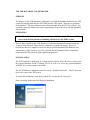
TPS XYR DATABASE CONFIGURATOR
PURPOSE
The purpose of the XYR Database Configurator is to build the database required by the TPS
system for bringing data from the XYR 5000 into the TPS system. There are two portions
to the database. The array database where all data brought in by the SI-FTA is placed. The
secondary (optional) database provides an opportunity to move the array data into alarmable
data locations.
OPERATION
NOTE: The XYR Database Configurator is for use ONLY with the TPS system. It is
not created with the intention of building a database for the EPKS system.
There is data required by the XYR Database Configurator that must be obtained from the
existing Control System. Once entered, a database is created very simply. However,
because the data to be supplied is critical to the successful operation of the database (and
subsequently, of the Gateway), it is fully expected that this database will be created and
loaded onto the TPS system by plant engineering personnel.
INSTALLATION
The XYR Database Configurator is a simple tool provided to allow the user to easily create
the required database for the XYRadio SI-FTA as well as to create any optional database
and PM/CL for value storage on the HPM.
The XYR Database Configurator must be run on a Windows based PC. This PC does not
have to be a part of the TPS system.
To install the configurator, from the provided CD, execute the file ‘Setup.exe’.
Once executing, the program will begin its installation.
Click ‘Next’ to continue.
If the installation path is incorrect, first select ‘Change’ and select the desired path for
installation of the XYR Database Configurator. Once the installation path is correct, select
‘Next’ to continue.
To being the installation, click on the ‘Install’ button. The XYR Database Configurator will
install itself at the indicated path.
Revision 1.02
Serial Interface FTA for XYR 5000 User Manual - 34-XY-25-14
Page 42 of 91
30 April 2007
A successful installation will be indicated with the ‘Complete’ screen. Select ‘Finish’ to
close the window.
EXECUTION
The XYRadio Configurator can be found using the following selection:
‘Start/All Programs/Honeywell/XYRadio Configurator’
Using that path, select the ‘Launch XYR 5000 Config.exe’.
The following screen will be displayed:
The Menu Bar provides two main choices: ‘Session’ and ‘About’.
The ‘Session’ selection will provide the option to save the current session, to read in a saved
session, or to exit the current session. At any time, the user may either load a previously
saved session or save the current session for future use.
The ‘About’ selection provides the user the Version number for the running configurator.
Revision 1.02
Serial Interface FTA for XYR 5000 User Manual - 34-XY-25-14
Page 43 of 91
30 April 2007
Some general notes about the left side of the configurator window:
• The left side of the configurator window represents configured elements of the
system. Immediately, you will see ‘XYRadio’ and ‘Base Radio Online’, ‘Process
Module Points’, and ‘Radio_1’.
• Clicking on the ‘+’ for each will open up configured data.
• When the default point name (tag name) is shown, a ‘right click’ of the mouse will
allow the user to change the name to match system requirements.
• A point for ‘Base Radio Online’ is shown, but is only utilized if an extended
database is generated.
• A Process Module Point (Procmod) is generated and shown, but is only utilized if an
extended database is generated.
• Until transmitters are selected, there are no entries under ‘Radio_1’.
The right side of the configurator window allows the user to input pertinent data for the
building of a valid database.
Version
The first block on the right side will eventually allow a version selection. For now, the only
version available is ‘Version 1’.
SI Arrays
The number of arrays required for a given number of transmitters is shown to help
determine the number of transmitters and arrays to plan for. For example, if you need 7
transmitters, it may be as well to configure for 10 so that if there is expansion later, there
will be less work.
Revision 1.02
Serial Interface FTA for XYR 5000 User Manual - 34-XY-25-14
Page 44 of 91
30 April 2007
General Information
This data must be obtained from the plant personnel to accurately reflect the specific
configuration of your plant.
• Node Type: The Node Type may be selected using the drop-down menu as either
HPM or APM. The selection will affect data entry validation for certain types of
data.
• Unit: Unit is an entry for the LCN Unit ID and must meet LCN standards for Unit
Identification.
• Base Tag Name: All default tagnames will have this entry as a prefix. Note that
tagnames may be manually changed before the final database is generated.
• xPM Node #: This entry represents the LCN Node number of the xPM where the
database for the XYR5000 SI-FTA will be loaded.
• xPM Network #: xPM Network is an entry that indicates the UCN Network number
where the xPM resides.
• Number of Transmitters: This entry will size the array database to house this
number of transmitters. This entry also affects the transmitters that may be selected
for inclusion. This number should match or exceed the number of transmitters
configured in the XYR 5000 Base Radio. Note that the larger this number becomes,
the more array points are defined for addition to the system. If the space is
available, we recommend configuring now for 50 transmitters to remove the
trouble of having to add database at a later date. However, also recognize that
there is a range of transmitters associated with each Serial Interface array. For
example, if you have 6 transmitters, it may be well to configure for 10 at this time.
See the table Table 2 - Transmitter vs. Array Requirements on page 2.
NOTE:If the database is set to accommodate (for example) 20 transmitters and the
actual number of transmitters are currently 10, an additional 10 may be added
with no impact to the system.
NOTE:If additional transmitters are added at a later date, a new SI array may be
required (see Table 2 - Transmitter vs. Array Requirements), plus all the Flag
Points, Numeric Points, RegPV Points, and/or CL that would be required to
accommodate the alarming and scaling for these new transmitters. The
Configurator Program can be used to build this database at later time by loading
the last configuration (nominally in a file named XYRLoad.ini), making the
changes to add the new transmitters, and generating a new set of database files.
The .EB files are set to NOT overwrite existing database, but the existing points will
be included in the database and will produce an error at load time. That error will
Revision 1.02
Serial Interface FTA for XYR 5000 User Manual - 34-XY-25-14
Page 45 of 91
30 April 2007
prevent the XYRLDOTH.EC file from recompiling the CL and from moving the
resultant CL object files. However, that can be done manually.
NOTE:If transmitters are removed at a later date, simply change the number of
configured transmitters on the Base Radio.
Array Configuration
The array database must reflect certain information about the system and about the
communication setup.
•
•
•
•
•
•
•
•
Baud Rate: The Baud Rate or rate of communication must be determined and
selected. Selections may be made from the drop-down menu.
Parity: Using the drop-down menu, select Odd, Even, or None for the parity used in
communication.
Signaling Protocol: Using the drop-down menu, select RS485 or RS232. The
default and standard for the XYR 5000 Base radio is RS485.
Message Timeout: Enter here the communication timeout value for the Modbus
communications. This represents the time (in seconds) before a failure is determined
and retry will occur. The range is between 0.25 sec and 5.0 sec.
Modbus ID #: This is the Modbus address of the XYR 5000 Base Radio.
IOPNUM: This is the slot number the SI IOP is mounted in. The range is 1 - 40.
FTANUM: The FTANUM defines whether the FTA is connected as the first or the
second FTA. Note that FTA 1 is connected on the left side of the FTA’s power
supply. FTA 2 is connected on the right side of the FTA’s power supply.
Beginning Array Slot: The first slot for the array database must be defined. Note
that the program presumes all slots are consecutive and are built as such. Manual
changes to the .EB files may be made as required. Only the resultant file
XYRBASE.EB will require modification in such a case.
History Module reference path
The History Module reference path is necessary to build the .EC files that will automate
your database and CL building. Indicate here the pathname on the LCN where the .EB, .CL,
and .EC files will be placed and executed. Note that the pathname must not end with a ‘>’.
Revision 1.02
Serial Interface FTA for XYR 5000 User Manual - 34-XY-25-14
Page 46 of 91
30 April 2007
Database Generation
This radio button selection will determine the extent of the database to be built. If
‘Generate Array database alone’ is selected, only the array database and associated files are
generated. When ‘Generate extended database’ is selected, all files for the CL, ProcMod
points, Numeric points, Flag points, and RegPV points as defined with the configurator will
be built.
The ‘Generate Database’ button may be selected to build the database once all configuration
is defined. Note that a successful ‘Array database’ can be built at this point. For an
‘Extended database’, the user will want to define transmitters and points for data storage
prior to generating the database.
To continue, select the ‘PV/Flag Points’ selection in the left pane.
Transmitters – PV/Flag Points
Revision 1.02
Serial Interface FTA for XYR 5000 User Manual - 34-XY-25-14
Page 47 of 91
30 April 2007
The number of transmitters presented in this section is a direct result of the prior selection of
‘Number of Transmitters’. The array database will be built to handle 6 transmitters. With
this selection, the user will be allowed to define extended storage of PV and Flag data.
Transmitters not selected here will not have the option of using the extended database.
Select the transmitters as appropriate. Note that with each selection, a ‘Transmitter_xx’ will
appear on the left pane of the Configurator.
Tag Settings – PV/Flag Points
When an extended database is defined, a number of parameters must be indicated to know
how to define the database properly.
•
•
•
•
•
•
Beginning alarmable flag slot: While the first alarmable flag slot is 1, it may not be
the first ‘available’ flag slot. Define the first ‘available’ alarmable flag slot here.
The slots are considered consecutive from this point. If this is not the case, the
resultant .EB file for the flag points may be manually manipulated.
Beginning Non-alarmable flag slot: There is a first ‘non-alarmable’ slot for flags
that will depend on the use of an APM or an HPM. The program takes that into
account. However, that slot may not be ‘available’. Define the first ‘available’ nonalarmable flag slot here. The slots are considered consecutive from this point. If
this is not the case, the resultant .EB file for the flag points may be manually
manipulated.
Beginning RegPV Slot: This is the first ‘available’ RegPV slot. The maximum
number of RegPVs that will be required is seven (7). The actual number will depend
upon your definition of how to treat data. Flag tags and Numeric tags affect this
count.
Beginning Numeric Slot: This will be the first ‘available’ Numeric slot on the xPM.
The slots are considered consecutive from this point. If this is not the case, the
resultant .EB file for the numeric (PV) points may be manually manipulated.
Beginning Process Module slot: This should be the first ‘available’ ProcMod slot on
the xPM. The slots are considered consecutive from this point. If this is not the
case, the resultant .EB file for the ProcMod points may be manually manipulated.
Base Radio Online: With this selection, a determination is made if the ‘Base Radio
Online’ flag will be alarmable or not. If an extended database is configured, a flag
for the base radio’s online status will always be generated, along with a ProcMod
and CL to process it.
Revision 1.02
Serial Interface FTA for XYR 5000 User Manual - 34-XY-25-14
Page 48 of 91
30 April 2007
Default Settings
Because up to 50 transmitters may be selected, there may be a very large database to
configure. In order to help make this task simpler, if all the values of a certain type are
expected to be either alarmable or stored into numeric points, this may be indicated at this
time by selecting the appropriate indicator. If no ‘extended’ database will be built for a
certain type, then leave the selection as ‘None’ or ‘No flags’. That selection is the default.
The PV/Flag settings for each transmitter may be later modified using the Configurator
program.
Flag mnemonics
Up to 10 flags may be created to provide a .PVFL for the status data on each transmitter. As
a default, the ‘Base Tagname’ is combined with the a ‘Txx’ for the transmitter number and
the mnemonics defined here as a tagname for the flags. The flags are as follows:
•
•
•
•
•
•
•
•
•
•
Onln – Online / Offline Status of the transmitter
LBat – Low Battery
Alrm – In Alarm
SenE – Sensor Error
ORng – Overrange condition in effect
SysE – System Error
S1Hi – Switch 1 is High
S2Hi – Switch 2 is High
SROn – Square Root Function in effect
RSts – Future use
The final set of selections is based on the configuration the individual transmitters.
Revision 1.02
Serial Interface FTA for XYR 5000 User Manual - 34-XY-25-14
Page 49 of 91
30 April 2007
With this page, the user may select individual PVs and/or Flags for transfer to optional Flag,
Numeric, or RegPV points. PVs selected as RegPV (provides alarming and limit checking)
will have their array value moved to RegPV points. PVs selected as ‘Numeric’ will have
their array value moved to Numeric points. Flags selected as ‘Alarmable’ will have their
array value moved to Flag points with alarming capability. Flags selected as ‘NonAlarmable’ will have their array value moved to Flag points without alarming capability (as
per the index entered by the user).
PV Configuration – Radio_1-Transmitter_xx
There are potentially 3 PVs which may be configured to be transferred to RegPV or
Numeric points. It should be noted that not all transmitters utilize all PVs. To minimize the
effective database created, unused PVx values should be selected as ‘none’.
Alarm Status – Radio_1-Transmitter_xx
Revision 1.02
Serial Interface FTA for XYR 5000 User Manual - 34-XY-25-14
Page 50 of 91
30 April 2007
Up to 10 flags for each transmitter may have a value transferred from data received from the
XYR 5000 Base Radio. That definition is made here. An extended database reflecting the
choices made here will be made when the ‘Generate Database’ button is selected.
Once the configuration data is all entered, the user will select the ‘Generate Database’
button. This will cause the XYR Database Configurator to calculate and build the .EB files,
the .CL files, and the .EC files for database and CL building.
When the files are being built, if the files already exist, the user will be asked to verify
overstoring the existing files. The user will first be allowed to choose the location for the
new files being built. Even if the selection on the first page was to generate only the ‘Array
database’, once the first, required files are built, the user will be asked:
The extended database refers to the optional database that will be built for storing the data
as indicated by the selections made with the XYR Database Configurator. This is the
database that will provide Flag, Numeric, RegPV, and ProcMod points on the TPS system
as desired for storage of the array data into more ‘normal’ PV type points.
Once the extended database is created, notification will occur and the current session will be
saved.
The files created are as follows (showing the default point prefixes):
Revision 1.02
Serial Interface FTA for XYR 5000 User Manual - 34-XY-25-14
Page 51 of 91
30 April 2007
File Name
XYRLDARR.EC
XYRDBARR.EC
XYRLDOTH.EC
XYRDBOTH.EC
XYRBase.EB
XYR011.CL (up to XYR017.CL)
XYRFlag.EB
XYRLoad.ini
XYRPrcM.EB
XYRPV.EB
Contains
Master .EC file used for Array database load
.EC file used by XYRLDARR.EC for building
and loading the Array database
Master .EC file used for non Array database
load and .CL compile
.EC file used by XYRLDOTH.EC for
compiling and loading the Non-Array database
.EB file for the Array points
.CL for the ProcMod point (if indicated)
.EB file with the Flag points
This is the default ‘Save’ file for the
current/last session.
.EB file with the ProcMod point
.EB file with the RegPV and Numeric points
Table 9 - Files built by XYR Configurator
Examine at the .EB files created. The user will need to verify that these files contain the
locations, settings, point names, etc. that are expected and make any changes that might be
necessary. Any alarm limits must be manually entered. While the XYR Database
Configurator is not an absolute foolproof process, it will do most if not all of the work in
preparing the files you will need.
The files are ready to be copied to the LCN History Module. There are a number of
methods for doing this. We recommend that the files be moved by plant engineering
personnel with an understanding of the TPS HM structure and how to move files from a PC
format to the LCN format. A typical method for moving the file would be to use the ‘File
Transfer’ utility that is run on GUS stations.
From this point on, any errors are standard LCN Command Processor errors and can be
investigated using standard TDC3000/TPS documentation.
To create the database on the LCN, several .EC files are provided – XYRLDARR.EC for
the required Array Database and XYRLDOTH.EC for the optional data functions. From the
Command Processor, having set the proper path (SP NET>xxxx>), type: EC
XYRLDARR.EC <Enter> to build the array database. Similarly, for the extended database
points and CL, type XYRLDOTH.EC <Enter> to build that portion of the database. The
.EB files built by the Configurator will then be run through the Exception Build and Load
process. If there are no errors, the .CL file will also be compiled for use with the ProcMod
point. Once built, it copies itself into the proper path for the indicated UCN and xPM Node.
It will be up to the user to connect the CL to the ProcMod point. See the TPS/TDC
documentation about Process Module (ProcMod) points and their use in the Advanced
Process Manager Control Functions and Algorithms (AP09-xxx).
It would be a good idea to do a save on the HPM data at this point to keep from having to
reinitiate the database building effort.
Revision 1.02
Serial Interface FTA for XYR 5000 User Manual - 34-XY-25-14
Page 52 of 91
30 April 2007
Revision 1.02
Serial Interface FTA for XYR 5000 User Manual - 34-XY-25-14
Page 53 of 91
30 April 2007
TPS / XYR 5000 DIAGNOSTIC SCHEMATIC
A simple native window TPS Schematic is provided with the package to allow the plant
personnel the ability to see which transmitters are connected and what the current PV values
(PV1, PV2, and PV3) are.
There are two files on the CD which must be loaded onto the TPS History Module. Using
the same method as used in transferring the database and CL files built by the XYR
Database Configurator, copy the following files to the History Module:
•
•
XYR_DIAG.DS
XYRDDB.DF
The TPS graphic must be compiled on the target system to be useable. This can only be
accomplished once the Array database has been successfully loaded sicne the graphic will
access that database.
To modify and compile the TPS schematic, the following steps are provided:
From an station loaded with ether the Engineering Personality or the Universal Personality,
enter the Picture Editor.
Set the pathname to the volume where the .DS and .DF files were placed on the History
Module (SP NET>xxx>).
Enter the command LOAD XYRDDB
Enter the command READ XYR_DIAG to read in the schematic in preparation for possible
modification.
Revision 1.02
Serial Interface FTA for XYR 5000 User Manual - 34-XY-25-14
Page 54 of 91
30 April 2007
Enter the command DEFINE INIT
Revision 1.02
Serial Interface FTA for XYR 5000 User Manual - 34-XY-25-14
Page 55 of 91
30 April 2007
At this point, the user will see a number of point names (here shown as XYR01_01 through
XYR01_15).
• The point names must match those array point names that were loaded onto the
system.
• If point names other than the default set were used, these must be modified to match
the actual point names.
• Select the point names and modify them to match.
• If an array has not been loaded, that line must be deleted or the schematic will not
compile.
For example, if 5 or fewer transmitters are configured into the system, only the first four
lines would be retained (see Table 2 - Transmitter vs. Array Requirements).
Compile the schematic (COM), ensuring it is available in a volume searched by the
schematic request.
The completed schematic will show ‘online’ transmitters, the 3 PV values, the type of the
transmitter, how many transmitters the base radio is configured for, and how many are
responding. Note that the values and types represented within this document are simulated
for display purposes only and do not reflect the actual types of numbers one may expect to
see.
There are two messages that may appear on the graphic.
Database Incomplete: One of two things is happening here. One - the Base Radio may be
configured to handle more transmitters than is the database on the TDC 3000. Two – the
additional array database has been added, but the “DEFINE INIT” task in modifying the
schematic has not been modified to include the new array.
Revision 1.02
Serial Interface FTA for XYR 5000 User Manual - 34-XY-25-14
Page 56 of 91
30 April 2007
Transmitter Not Configured: The array database has been sized to handle this transmitter,
but the base radio is a number smaller than the number allowed by virtue of the database
loaded. When the Base Radio is sized to that point, if a new transmitter is enabled, the PV
values will be shown.
Revision 1.02
Serial Interface FTA for XYR 5000 User Manual - 34-XY-25-14
Page 57 of 91
30 April 2007
SAMPLE DATABASES AND CL
These databases and CL examples are intended as a sample of the both the base required
Array database and the Extended database. Point names, Unit names, slot numbers, scaling,
and other defineable parameters would need to be adjusted according to plant requirements.
It should be noted that changes to a point name must be reflected in the following databases
as well:
TAG TYPE
Array
Flag
Numeric
RegPV
ProcMod
ALSO CHECK
xPM CL code; the DEF INIT page on the XYR_DIAG
schematic
xPM CL Code
xPM CL Code
Changing the RegPV Tag name should have no impact on
other databases or on the XYR_DIAG schematic.
Changing the ProcMod tag name will require a change in the
non-generic xPM CL that will be attached to that tag.
Table 10 - Checks for Manual Point Name Changes
Revision 1.02
Serial Interface FTA for XYR 5000 User Manual - 34-XY-25-14
Page 58 of 91
30 April 2007
SAMPLE xPM ARRAY DATABASE
The following table provides a nominal .EB file for all fifteen (15) base array points. The
first four (4) arrays are required in any configuration. These data in these files may be used
for building the arrays manually. Once the first four (4) arrays are built, the XYR SI-FTA
should be able to communicate with the XYR 5000 Base Radio. Other arrays may be built
as required (reference Table 2 - Transmitter vs. Array Requirements).
The first four (4) arrays have cells highlighted in yellow where the user would normally
modify the contents to fit the specific requirements at the user’s site. While other data may
be modified, these are the most common.
Note that in the first four (4) arrays, there are also cells highlighted in green. These contents
must not be modified.
Revision 1.02
Serial Interface FTA for XYR 5000 User Manual - 34-XY-25-14
Page 59 of 91
30 April 2007
{SYSTEM ENTITY X_ARR01( )}
&T ARRAY
&N X_ARR01
NODETYP = HPM
PNTFORM = FULL
PTDESC = "ARRAY_ActionFlags"
KEYWORD = "
"
ASSOCDSP = "
"
$CDETAIL = "
"
UNIT = a1
NTWKNUM = 1
NODENUM = 1
MODNUM = 0
SLOTNUM = 1
PRIMMOD = ________
USERID = "----------------"
EXTDATA = IO_FL
IOPNUM = 1
FTANUM = 1
DEVADDR = 15
SCANPRI = LOW
AUXDATA1 = 15
AB_DATA1 = -------AUXDATA2 = 1
AB_DATA2 = 0.5
AUXDATA3 = 485.0
AB_DATA3 = 0
AUXDATA4 = 9600.0
AB_DATA4 = 1
FLSTIX = 333
NFLAG = 151
NNSTIX = 0
NNUMERIC = 0
STRSTIX = 0
STRLEN = 8
NSTRING = 0
TIMESTIX = 0
NTIME = 0
SPLOCK = OPERATOR
FLDESC = "
NNDESC = "
STRDESC = "
TIMEDESC = "
$ADD = ON
Revision 1.02
"
"
"
"
Serial Interface FTA for XYR 5000 User Manual - 34-XY-25-14
Page 60 of 91
30 April 2007
{SYSTEM ENTITY X_ARR02( )}
&T ARRAY
&N X_ARR02
NODETYP = HPM
PNTFORM = FULL
PTDESC = "ARRAY_DeviceType"
KEYWORD = "
"
ASSOCDSP = "
"
$CDETAIL = "
"
UNIT = a1
NTWKNUM = 1
NODENUM = 1
MODNUM = 0
SLOTNUM = 2
PRIMMOD = ________
USERID = "----------------"
EXTDATA = IO_NN
IOPNUM = 1
FTANUM = 1
DEVADDR = 0
SCANPRI = LOW
AUXDATA1 = 11
AB_DATA1 = -------AUXDATA2 = -------AB_DATA2 = -------AUXDATA3 = -------AB_DATA3 = -------AUXDATA4 = -------AB_DATA4 = -------FLSTIX = 0
NFLAG = 0
NNSTIX = 999
NNUMERIC = 27
STRSTIX = 0
STRLEN = 8
NSTRING = 0
TIMESTIX = 0
NTIME = 0
SPLOCK = OPERATOR
FLDESC = "
NNDESC = "
STRDESC = "
TIMEDESC = "
$ADD = ON
Revision 1.02
"
"
"
"
Serial Interface FTA for XYR 5000 User Manual - 34-XY-25-14
Page 61 of 91
30 April 2007
{SYSTEM ENTITY X_ARR03( )}
&T ARRAY
&N X_ARR03
NODETYP = HPM
PNTFORM = FULL
PTDESC = "ARRAY_StatusFlags"
KEYWORD = "
"
ASSOCDSP = "
"
$CDETAIL = "
"
UNIT = a1
NTWKNUM = 1
NODENUM = 1
MODNUM = 0
SLOTNUM = 3
PRIMMOD = ________
USERID = "----------------"
EXTDATA = IO_FL
IOPNUM = 1
FTANUM = 1
DEVADDR = 0
SCANPRI = LOW
AUXDATA1 = 13
AB_DATA1 = -------AUXDATA2 = -------AB_DATA2 = -------AUXDATA3 = -------AB_DATA3 = -------AUXDATA4 = -------AB_DATA4 = -------FLSTIX = 484
NFLAG = 250
NNSTIX = 0
NNUMERIC = 0
STRSTIX = 0
STRLEN = 8
NSTRING = 0
TIMESTIX = 0
NTIME = 0
SPLOCK = OPERATOR
FLDESC = "
NNDESC = "
STRDESC = "
TIMEDESC = "
$ADD = ON
Revision 1.02
"
"
"
"
Serial Interface FTA for XYR 5000 User Manual - 34-XY-25-14
Page 62 of 91
30 April 2007
{SYSTEM ENTITY X_ARR04( )}
&T ARRAY
&N X_ARR04
NODETYP = HPM
PNTFORM = FULL
PTDESC = "ARRAY_PVVal"
KEYWORD = "
"
ASSOCDSP = "
"
$CDETAIL = "
"
UNIT = a1
NTWKNUM = 1
NODENUM = 1
MODNUM = 0
SLOTNUM = 4
PRIMMOD = ________
USERID = "----------------"
EXTDATA = IO_NN
IOPNUM = 1
FTANUM = 1
DEVADDR = 0
SCANPRI = LOW
AUXDATA1 = 1
AB_DATA1 = -------AUXDATA2 = -------AB_DATA2 = -------AUXDATA3 = -------AB_DATA3 = -------AUXDATA4 = -------AB_DATA4 = -------FLSTIX = 0
NFLAG = 0
NNSTIX = 1026
NNUMERIC = 15
STRSTIX = 0
STRLEN = 8
NSTRING = 0
TIMESTIX = 0
NTIME = 0
SPLOCK = OPERATOR
FLDESC = "
NNDESC = "
STRDESC = "
TIMEDESC = "
$ADD = ON
Revision 1.02
"
"
"
"
Serial Interface FTA for XYR 5000 User Manual - 34-XY-25-14
Page 63 of 91
30 April 2007
{SYSTEM ENTITY X_ARR05( )}
&T ARRAY
&N X_ARR05
NODETYP = HPM
PNTFORM = FULL
PTDESC = "ARRAY_PVVal"
KEYWORD = "
"
ASSOCDSP = "
"
$CDETAIL = "
"
UNIT = a1
NTWKNUM = 1
NODENUM = 1
MODNUM = 0
SLOTNUM = 5
PRIMMOD = ________
USERID = "----------------"
EXTDATA = IO_NN
IOPNUM = 1
FTANUM = 1
DEVADDR = 0
SCANPRI = LOW
AUXDATA1 = 2
AB_DATA1 = -------AUXDATA2 = -------AB_DATA2 = -------AUXDATA3 = -------AB_DATA3 = -------AUXDATA4 = -------AB_DATA4 = -------FLSTIX = 0
NFLAG = 0
NNSTIX = 1041
NNUMERIC = 15
STRSTIX = 0
STRLEN = 8
NSTRING = 0
TIMESTIX = 0
NTIME = 0
SPLOCK = OPERATOR
FLDESC = "
NNDESC = "
STRDESC = "
TIMEDESC = "
$ADD = ON
Revision 1.02
"
"
"
"
Serial Interface FTA for XYR 5000 User Manual - 34-XY-25-14
Page 64 of 91
30 April 2007
{SYSTEM ENTITY X_ARR06( )}
&T ARRAY
&N X_ARR06
NODETYP = HPM
PNTFORM = FULL
PTDESC = "ARRAY_PVVal"
KEYWORD = "
"
ASSOCDSP = "
"
$CDETAIL = "
"
UNIT = a1
NTWKNUM = 1
NODENUM = 1
MODNUM = 0
SLOTNUM = 6
PRIMMOD = ________
USERID = "----------------"
EXTDATA = IO_NN
IOPNUM = 1
FTANUM = 1
DEVADDR = 0
SCANPRI = LOW
AUXDATA1 = 3
AB_DATA1 = -------AUXDATA2 = -------AB_DATA2 = -------AUXDATA3 = -------AB_DATA3 = -------AUXDATA4 = -------AB_DATA4 = -------FLSTIX = 0
NFLAG = 0
NNSTIX = 1056
NNUMERIC = 15
STRSTIX = 0
STRLEN = 8
NSTRING = 0
TIMESTIX = 0
NTIME = 0
SPLOCK = OPERATOR
FLDESC = "
NNDESC = "
STRDESC = "
TIMEDESC = "
$ADD = ON
Revision 1.02
"
"
"
"
Serial Interface FTA for XYR 5000 User Manual - 34-XY-25-14
Page 65 of 91
30 April 2007
{SYSTEM ENTITY X_ARR07( )}
&T ARRAY
&N X_ARR07
NODETYP = HPM
PNTFORM = FULL
PTDESC = "ARRAY_PVVal"
KEYWORD = "
"
ASSOCDSP = "
"
$CDETAIL = "
"
UNIT = a1
NTWKNUM = 1
NODENUM = 1
MODNUM = 0
SLOTNUM = 7
PRIMMOD = ________
USERID = "----------------"
EXTDATA = IO_NN
IOPNUM = 1
FTANUM = 1
DEVADDR = 0
SCANPRI = LOW
AUXDATA1 = 4
AB_DATA1 = -------AUXDATA2 = -------AB_DATA2 = -------AUXDATA3 = -------AB_DATA3 = -------AUXDATA4 = -------AB_DATA4 = -------FLSTIX = 0
NFLAG = 0
NNSTIX = 1071
NNUMERIC = 15
STRSTIX = 0
STRLEN = 8
NSTRING = 0
TIMESTIX = 0
NTIME = 0
SPLOCK = OPERATOR
FLDESC = "
NNDESC = "
STRDESC = "
TIMEDESC = "
$ADD = ON
Revision 1.02
"
"
"
"
Serial Interface FTA for XYR 5000 User Manual - 34-XY-25-14
Page 66 of 91
30 April 2007
{SYSTEM ENTITY X_ARR08( )}
&T ARRAY
&N X_ARR08
NODETYP = HPM
PNTFORM = FULL
PTDESC = "ARRAY_PVVal"
KEYWORD = "
"
ASSOCDSP = "
"
$CDETAIL = "
"
UNIT = a1
NTWKNUM = 1
NODENUM = 1
MODNUM = 0
SLOTNUM = 8
PRIMMOD = ________
USERID = "----------------"
EXTDATA = IO_NN
IOPNUM = 1
FTANUM = 1
DEVADDR = 0
SCANPRI = LOW
AUXDATA1 = 5
AB_DATA1 = -------AUXDATA2 = -------AB_DATA2 = -------AUXDATA3 = -------AB_DATA3 = -------AUXDATA4 = -------AB_DATA4 = -------FLSTIX = 0
NFLAG = 0
NNSTIX = 1086
NNUMERIC = 15
STRSTIX = 0
STRLEN = 8
NSTRING = 0
TIMESTIX = 0
NTIME = 0
SPLOCK = OPERATOR
FLDESC = "
NNDESC = "
STRDESC = "
TIMEDESC = "
$ADD = ON
Revision 1.02
"
"
"
"
Serial Interface FTA for XYR 5000 User Manual - 34-XY-25-14
Page 67 of 91
30 April 2007
{SYSTEM ENTITY X_ARR09( )}
&T ARRAY
&N X_ARR09
NODETYP = HPM
PNTFORM = FULL
PTDESC = "ARRAY_DeviceType"
KEYWORD = "
"
ASSOCDSP = "
"
$CDETAIL = "
"
UNIT = a1
NTWKNUM = 1
NODENUM = 1
MODNUM = 0
SLOTNUM = 9
PRIMMOD = ________
USERID = "----------------"
EXTDATA = IO_NN
IOPNUM = 1
FTANUM = 1
DEVADDR = 0
SCANPRI = LOW
AUXDATA1 = 12
AB_DATA1 = -------AUXDATA2 = -------AB_DATA2 = -------AUXDATA3 = -------AB_DATA3 = -------AUXDATA4 = -------AB_DATA4 = -------FLSTIX = 0
NFLAG = 0
NNSTIX = 1101
NNUMERIC = 25
STRSTIX = 0
STRLEN = 8
NSTRING = 0
TIMESTIX = 0
NTIME = 0
SPLOCK = OPERATOR
FLDESC = "
NNDESC = "
STRDESC = "
TIMEDESC = "
$ADD = ON
Revision 1.02
"
"
"
"
Serial Interface FTA for XYR 5000 User Manual - 34-XY-25-14
Page 68 of 91
30 April 2007
{SYSTEM ENTITY X_ARR10( )}
&T ARRAY
&N X_ARR10
NODETYP = HPM
PNTFORM = FULL
PTDESC = "ARRAY_StatusFlags"
KEYWORD = "
"
ASSOCDSP = "
"
$CDETAIL = "
"
UNIT = a1
NTWKNUM = 1
NODENUM = 1
MODNUM = 0
SLOTNUM = 10
PRIMMOD = ________
USERID = "----------------"
EXTDATA = IO_FL
IOPNUM = 1
FTANUM = 1
DEVADDR = 0
SCANPRI = LOW
AUXDATA1 = 14
AB_DATA1 = -------AUXDATA2 = -------AB_DATA2 = -------AUXDATA3 = -------AB_DATA3 = -------AUXDATA4 = -------AB_DATA4 = -------FLSTIX = 734
NFLAG = 250
NNSTIX = 0
NNUMERIC = 0
STRSTIX = 0
STRLEN = 8
NSTRING = 0
TIMESTIX = 0
NTIME = 0
SPLOCK = OPERATOR
FLDESC = "
NNDESC = "
STRDESC = "
TIMEDESC = "
$ADD = ON
Revision 1.02
"
"
"
"
Serial Interface FTA for XYR 5000 User Manual - 34-XY-25-14
Page 69 of 91
30 April 2007
{SYSTEM ENTITY X_ARR11( )}
&T ARRAY
&N X_ARR11
NODETYP = HPM
PNTFORM = FULL
PTDESC = "ARRAY_PVVal"
KEYWORD = "
"
ASSOCDSP = "
"
$CDETAIL = "
"
UNIT = a1
NTWKNUM = 1
NODENUM = 1
MODNUM = 0
SLOTNUM = 11
PRIMMOD = ________
USERID = "----------------"
EXTDATA = IO_NN
IOPNUM = 1
FTANUM = 1
DEVADDR = 0
SCANPRI = LOW
AUXDATA1 = 6
AB_DATA1 = -------AUXDATA2 = -------AB_DATA2 = -------AUXDATA3 = -------AB_DATA3 = -------AUXDATA4 = -------AB_DATA4 = -------FLSTIX = 0
NFLAG = 0
NNSTIX = 1126
NNUMERIC = 15
STRSTIX = 0
STRLEN = 8
NSTRING = 0
TIMESTIX = 0
NTIME = 0
SPLOCK = OPERATOR
FLDESC = "
NNDESC = "
STRDESC = "
TIMEDESC = "
$ADD = ON
Revision 1.02
"
"
"
"
Serial Interface FTA for XYR 5000 User Manual - 34-XY-25-14
Page 70 of 91
30 April 2007
{SYSTEM ENTITY X_ARR12( )}
&T ARRAY
&N X_ARR12
NODETYP = HPM
PNTFORM = FULL
PTDESC = "ARRAY_PVVal"
KEYWORD = "
"
ASSOCDSP = "
"
$CDETAIL = "
"
UNIT = a1
NTWKNUM = 1
NODENUM = 1
MODNUM = 0
SLOTNUM = 12
PRIMMOD = ________
USERID = "----------------"
EXTDATA = IO_NN
IOPNUM = 1
FTANUM = 1
DEVADDR = 0
SCANPRI = LOW
AUXDATA1 = 7
AB_DATA1 = -------AUXDATA2 = -------AB_DATA2 = -------AUXDATA3 = -------AB_DATA3 = -------AUXDATA4 = -------AB_DATA4 = -------FLSTIX = 0
NFLAG = 0
NNSTIX = 1141
NNUMERIC = 15
STRSTIX = 0
STRLEN = 8
NSTRING = 0
TIMESTIX = 0
NTIME = 0
SPLOCK = OPERATOR
FLDESC = "
NNDESC = "
STRDESC = "
TIMEDESC = "
$ADD = ON
Revision 1.02
"
"
"
"
Serial Interface FTA for XYR 5000 User Manual - 34-XY-25-14
Page 71 of 91
30 April 2007
{SYSTEM ENTITY X_ARR13( )}
&T ARRAY
&N X_ARR13
NODETYP = HPM
PNTFORM = FULL
PTDESC = "ARRAY_PVVal"
KEYWORD = "
"
ASSOCDSP = "
"
$CDETAIL = "
"
UNIT = a1
NTWKNUM = 1
NODENUM = 1
MODNUM = 0
SLOTNUM = 13
PRIMMOD = ________
USERID = "----------------"
EXTDATA = IO_NN
IOPNUM = 1
FTANUM = 1
DEVADDR = 0
SCANPRI = LOW
AUXDATA1 = 8
AB_DATA1 = -------AUXDATA2 = -------AB_DATA2 = -------AUXDATA3 = -------AB_DATA3 = -------AUXDATA4 = -------AB_DATA4 = -------FLSTIX = 0
NFLAG = 0
NNSTIX = 1156
NNUMERIC = 15
STRSTIX = 0
STRLEN = 8
NSTRING = 0
TIMESTIX = 0
NTIME = 0
SPLOCK = OPERATOR
FLDESC = "
NNDESC = "
STRDESC = "
TIMEDESC = "
$ADD = ON
Revision 1.02
"
"
"
"
Serial Interface FTA for XYR 5000 User Manual - 34-XY-25-14
Page 72 of 91
30 April 2007
{SYSTEM ENTITY X_ARR14( )}
&T ARRAY
&N X_ARR14
NODETYP = HPM
PNTFORM = FULL
PTDESC = "ARRAY_PVVal"
KEYWORD = "
"
ASSOCDSP = "
"
$CDETAIL = "
"
UNIT = a1
NTWKNUM = 1
NODENUM = 1
MODNUM = 0
SLOTNUM = 14
PRIMMOD = ________
USERID = "----------------"
EXTDATA = IO_NN
IOPNUM = 1
FTANUM = 1
DEVADDR = 0
SCANPRI = LOW
AUXDATA1 = 9
AB_DATA1 = -------AUXDATA2 = -------AB_DATA2 = -------AUXDATA3 = -------AB_DATA3 = -------AUXDATA4 = -------AB_DATA4 = -------FLSTIX = 0
NFLAG = 0
NNSTIX = 1171
NNUMERIC = 15
STRSTIX = 0
STRLEN = 8
NSTRING = 0
TIMESTIX = 0
NTIME = 0
SPLOCK = OPERATOR
FLDESC = "
NNDESC = "
STRDESC = "
TIMEDESC = "
$ADD = ON
Revision 1.02
"
"
"
"
Serial Interface FTA for XYR 5000 User Manual - 34-XY-25-14
Page 73 of 91
30 April 2007
{SYSTEM ENTITY X_ARR15( )}
&T ARRAY
&N X_ARR15
NODETYP = HPM
PNTFORM = FULL
PTDESC = "ARRAY_PVVal"
KEYWORD = "
"
ASSOCDSP = "
"
$CDETAIL = "
"
UNIT = a1
NTWKNUM = 1
NODENUM = 1
MODNUM = 0
SLOTNUM = 15
PRIMMOD = ________
USERID = "----------------"
EXTDATA = IO_NN
IOPNUM = 1
FTANUM = 1
DEVADDR = 0
SCANPRI = LOW
AUXDATA1 = 10
AB_DATA1 = -------AUXDATA2 = -------AB_DATA2 = -------AUXDATA3 = -------AB_DATA3 = -------AUXDATA4 = -------AB_DATA4 = -------FLSTIX = 0
NFLAG = 0
NNSTIX = 1186
NNUMERIC = 15
STRSTIX = 0
STRLEN = 8
NSTRING = 0
TIMESTIX = 0
NTIME = 0
SPLOCK = OPERATOR
FLDESC = "
NNDESC = "
STRDESC = "
TIMEDESC = "
$ADD = ON
Revision 1.02
"
"
"
"
Serial Interface FTA for XYR 5000 User Manual - 34-XY-25-14
Page 74 of 91
30 April 2007
SAMPLE xPM ALARMABLE FLAG POINT
Sample xPM Alarm Flag Point
{SYSTEM ENTITY XYR_T01_Onln( )}
&T FLAGNIM
&N XYR_T01_Onln
NODETYP = APM
PNTFORM = FULL
PTDESC = "Transmitter Online"
EUDESC = "
"
KEYWORD = "
"
ASSOCDSP = "
"
$CDETAIL = "
"
UNIT = B1
NTWKNUM = 1
NODENUM = 9
SLOTNUM = 81
PRIMMOD = ________
STATETXT(1) = "OFF "
STATETXT(0) = "ON
"
PV
= OFF
BOXCLR(1) = YELLOW
BOXCLR(0) = GREEN
$AUXUNIT = -OFFNRMPR = LOW
ALENBST = ENABLE
EIPPCODE = ________
Revision 1.02
Serial Interface FTA for XYR 5000 User Manual - 34-XY-25-14
Page 75 of 91
30 April 2007
SAMPLE xPM NON-ALARMABLE FLAG POINT
Sample xPM Non-Alarmable Flag Point
{SYSTEM ENTITY XYR_T01_Onln( )}
&T FLAGNIM
&N XYR_T01_Onln
NODETYP = APM
PNTFORM = FULL
PTDESC = "Transmitter Online"
EUDESC = "
"
KEYWORD = "
"
ASSOCDSP = "
"
$CDETAIL = "
"
UNIT = B1
NTWKNUM = 1
NODENUM = 9
SLOTNUM = 601
PRIMMOD = ________
STATETXT(1) = "OFF "
STATETXT(0) = "ON
"
PV
= OFF
BOXCLR(1) = YELLOW
BOXCLR(0) = GREEN
Revision 1.02
Serial Interface FTA for XYR 5000 User Manual - 34-XY-25-14
Page 76 of 91
30 April 2007
SAMPLE xPM NUMERIC POINT
Sample xPM Numeric Point
{SYSTEM ENTITY XYR_PV2_T26( )}
&T NUMERNIM
&N XYR_PV2_T26
NODETYP = APM
PNTFORM = FULL
PTDESC = "Numeric_XYR_PV2_T26"
EUDESC = "
"
KEYWORD = "
"
ASSOCDSP = "
"
$CDETAIL = "
"
UNIT = B1
NTWKNUM = 1
NODENUM = 9
SLOTNUM = 26
PRIMMOD = ________
PV
= 0.0
PVFORMAT = D1
Revision 1.02
Serial Interface FTA for XYR 5000 User Manual - 34-XY-25-14
Page 77 of 91
30 April 2007
SAMPLE xPM REGPV POINT
Sample xPM RegPV Point
{SYSTEM ENTITY XYR_PV1_T01( )}
&T REGPVNIM
&N XYR_PV1_T01
NODETYP = APM
PNTFORM = FULL
PTDESC = "RegPV_XYR_PV1_T01"
EUDESC = "
"
KEYWORD = "
"
ASSOCDSP = "
"
$CDETAIL = "
"
UNIT = B1
NTWKNUM = 1
NODENUM = 9
MODNUM = 0
SLOTNUM = 1
PRIMMOD = ________
USERID = "----------------"
PVALGID = DATAACQ
PVEUHI = 100.0000
PVEULO = 0.000000
PVFORMAT = D1
PVEXEUHI = 102.90000
PVEXEULO = -2.90000
PVCLAMP = NOCLAMP
PVSRCOPT = ONLYAUTO
TF
= 0.000000
PVTV = -------OVERVAL = 25
PISRC(1) = XYR_ARR01.NN(1)
$AUXUNIT = -$ALDLOPT = NONE
DLYTIME = 0
PVALDB = ONE
PVHITP = -------PVLOTP = -------PVROCPTP = -------PVROCNTP = -------BADPVPR = LOW
ALENBST = ENABLE
Revision 1.02
Serial Interface FTA for XYR 5000 User Manual - 34-XY-25-14
Page 78 of 91
30 April 2007
SAMPLE xPM PROCMOD POINT
Sample xPM ProcMod Point
{SYSTEM ENTITY XYR_DataXFR1( )}
&T PRMODNIM
&N XYR_DataXFR1
NODETYP = APM
PNTFORM = FULL
PTDESC = "XYR Process Module1"
ASSOCDSP = "
"
$CDETAIL = "
"
UNIT = B1
NTWKNUM = 1
NODENUM = 9
SLOTNUM = 2
PRIMMOD = ________
USERID = "----------------"
STRLEN = 8
SEQSLTSZ = 100
CNTLLOCK = OPERATOR
SPLOCK = OPERATOR
RSTROPT = OFF
ACP = ____
CLBACK = 0
SEQPR = LOW
Revision 1.02
Serial Interface FTA for XYR 5000 User Manual - 34-XY-25-14
Page 79 of 91
30 April 2007
SAMPLE xPM CL
Sample xPM CL
SEQUENCE XYR1(APM ; POINT XYR_DataXFR1)
EXTERNAL XYR_DataXFR2
EXTERNAL XYR_ARR01
EXTERNAL XYR_ARR02
EXTERNAL XYR_ARR03
EXTERNAL XYR_ARR04
EXTERNAL XYR_ARR05
EXTERNAL XYR_ARR06
EXTERNAL XYR_ARR07
EXTERNAL XYR_ARR08
EXTERNAL XYR_ARR09
EXTERNAL XYR_ARR10
EXTERNAL XYR_ARR11
EXTERNAL XYR_ARR12
EXTERNAL XYR_ARR13
EXTERNAL XYR_ARR14
EXTERNAL XYR_ARR15
EXTERNAL XYR_PV2_T01
EXTERNAL XYR_T01_Onln
EXTERNAL XYR_T01_LBat
EXTERNAL XYR_T01_Alrm
EXTERNAL XYR_T01_SysE
EXTERNAL XYR_T01_ORng
EXTERNAL XYR_T01_SenE
EXTERNAL XYR_T01_S2Lo
EXTERNAL XYR_T01_S2Hi
EXTERNAL XYR_T01_SROn
EXTERNAL XYR_T01_RSts
EXTERNAL XYR_PV2_T02
EXTERNAL XYR_T02_Onln
EXTERNAL XYR_T02_LBat
EXTERNAL XYR_T02_Alrm
EXTERNAL XYR_T02_SysE
EXTERNAL XYR_T02_ORng
EXTERNAL XYR_T02_SenE
EXTERNAL XYR_T02_S2Lo
EXTERNAL XYR_T02_S2Hi
EXTERNAL XYR_T02_SROn
EXTERNAL XYR_T02_RSts
EXTERNAL XYR_PV2_T03
EXTERNAL XYR_T03_Onln
Revision 1.02
Serial Interface FTA for XYR 5000 User Manual - 34-XY-25-14
Page 80 of 91
30 April 2007
Sample xPM CL
EXTERNAL XYR_T03_LBat
EXTERNAL XYR_T03_Alrm
EXTERNAL XYR_T03_SysE
EXTERNAL XYR_T03_ORng
EXTERNAL XYR_T03_SenE
EXTERNAL XYR_T03_S2Lo
EXTERNAL XYR_T03_S2Hi
EXTERNAL XYR_T03_SROn
EXTERNAL XYR_T03_RSts
EXTERNAL XYR_PV2_T04
EXTERNAL XYR_T04_Onln
EXTERNAL XYR_T04_LBat
EXTERNAL XYR_T04_Alrm
EXTERNAL XYR_T04_SysE
EXTERNAL XYR_T04_ORng
EXTERNAL XYR_T04_SenE
EXTERNAL XYR_T04_S2Lo
EXTERNAL XYR_T04_S2Hi
EXTERNAL XYR_T04_SROn
EXTERNAL XYR_T04_RSts
EXTERNAL XYR_PV2_T05
EXTERNAL XYR_T05_Onln
EXTERNAL XYR_T05_LBat
EXTERNAL XYR_T05_Alrm
EXTERNAL XYR_T05_SysE
EXTERNAL XYR_T05_ORng
EXTERNAL XYR_T05_SenE
EXTERNAL XYR_T05_S2Lo
EXTERNAL XYR_T05_S2Hi
EXTERNAL XYR_T05_SROn
EXTERNAL XYR_T05_RSts
EXTERNAL XYR_PV2_T06
EXTERNAL XYR_T06_Onln
EXTERNAL XYR_T06_LBat
EXTERNAL XYR_T06_Alrm
EXTERNAL XYR_T06_SysE
EXTERNAL XYR_T06_ORng
EXTERNAL XYR_T06_SenE
EXTERNAL XYR_T06_S2Lo
EXTERNAL XYR_T06_S2Hi
EXTERNAL XYR_T06_SROn
EXTERNAL XYR_T06_RSts
EXTERNAL XYR_PV2_T07
Revision 1.02
Serial Interface FTA for XYR 5000 User Manual - 34-XY-25-14
Page 81 of 91
30 April 2007
Sample xPM CL
EXTERNAL XYR_T07_Onln
EXTERNAL XYR_T07_LBat
EXTERNAL XYR_T07_Alrm
EXTERNAL XYR_T07_SysE
EXTERNAL XYR_T07_ORng
EXTERNAL XYR_T07_SenE
EXTERNAL XYR_T07_S2Lo
EXTERNAL XYR_T07_S2Hi
EXTERNAL XYR_T07_SROn
EXTERNAL XYR_T07_RSts
EXTERNAL XYR_PV2_T08
EXTERNAL XYR_T08_Onln
EXTERNAL XYR_T08_LBat
EXTERNAL XYR_T08_Alrm
EXTERNAL XYR_T08_SysE
EXTERNAL XYR_T08_ORng
EXTERNAL XYR_T08_SenE
EXTERNAL XYR_T08_S2Lo
EXTERNAL XYR_T08_S2Hi
EXTERNAL XYR_T08_SROn
EXTERNAL XYR_T08_RSts
PHASE START
SET NN(1) = 0
SET NN(2) = 0
SET XYR_PV2_T01.PV = XYR_ARR04.nn(3) (WHEN ERROR call err_set(1))
SET XYR_T01_Onln.PVFL = not(XYR_ARR13.FL(1) (WHEN ERROR call err_set(2)))
SET XYR_T01_LBat.PVFL = XYR_ARR13.FL(51) (WHEN ERROR call err_set(3))
SET XYR_T01_Alrm.PVFL = XYR_ARR13.FL(101) (WHEN ERROR call err_set(4))
SET XYR_T01_SysE.PVFL = XYR_ARR13.FL(151) (WHEN ERROR call err_set(5))
SET XYR_T01_ORng.PVFL = XYR_ARR13.FL(201) (WHEN ERROR call err_set(6))
SET XYR_T01_SenE.PVFL = XYR_ARR14.FL(1) (WHEN ERROR call err_set(7))
SET XYR_T01_S2Lo.PVFL = XYR_ARR14.FL(51) (WHEN ERROR call err_set(8))
SET XYR_T01_S2Hi.PVFL = XYR_ARR14.FL(101) (WHEN ERROR call err_set(9))
SET XYR_T01_SROn.PVFL = XYR_ARR14.FL(151) (WHEN ERROR call err_set(10))
SET XYR_T01_RSts.PVFL = XYR_ARR14.FL(201) (WHEN ERROR call err_set(11))
SET XYR_PV2_T02.PV = XYR_ARR04.nn(4) (WHEN ERROR call err_set(12))
SET XYR_T02_Onln.PVFL = not(XYR_ARR13.FL(2) (WHEN ERROR call err_set(13)))
SET XYR_T02_LBat.PVFL = XYR_ARR13.FL(52) (WHEN ERROR call err_set(14))
SET XYR_T02_Alrm.PVFL = XYR_ARR13.FL(102) (WHEN ERROR call err_set(15))
SET XYR_T02_SysE.PVFL = XYR_ARR13.FL(152) (WHEN ERROR call err_set(16))
SET XYR_T02_ORng.PVFL = XYR_ARR13.FL(202) (WHEN ERROR call err_set(17))
SET XYR_T02_SenE.PVFL = XYR_ARR14.FL(2) (WHEN ERROR call err_set(18))
SET XYR_T02_S2Lo.PVFL = XYR_ARR14.FL(52) (WHEN ERROR call err_set(19))
Revision 1.02
Serial Interface FTA for XYR 5000 User Manual - 34-XY-25-14
Page 82 of 91
30 April 2007
Sample xPM CL
SET XYR_T02_S2Hi.PVFL = XYR_ARR14.FL(102) (WHEN ERROR call err_set(20))
SET XYR_T02_SROn.PVFL = XYR_ARR14.FL(152) (WHEN ERROR call err_set(21))
SET XYR_T02_RSts.PVFL = XYR_ARR14.FL(202) (WHEN ERROR call err_set(22))
SET XYR_PV2_T03.PV = XYR_ARR04.nn(5) (WHEN ERROR call err_set(23))
SET XYR_T03_Onln.PVFL = not(XYR_ARR13.FL(3) (WHEN ERROR call err_set(24)))
SET XYR_T03_LBat.PVFL = XYR_ARR13.FL(53) (WHEN ERROR call err_set(25))
SET XYR_T03_Alrm.PVFL = XYR_ARR13.FL(103) (WHEN ERROR call err_set(26))
SET XYR_T03_SysE.PVFL = XYR_ARR13.FL(153) (WHEN ERROR call err_set(27))
SET XYR_T03_ORng.PVFL = XYR_ARR13.FL(203) (WHEN ERROR call err_set(28))
SET XYR_T03_SenE.PVFL = XYR_ARR14.FL(3) (WHEN ERROR call err_set(29))
SET XYR_T03_S2Lo.PVFL = XYR_ARR14.FL(53) (WHEN ERROR call err_set(30))
SET XYR_T03_S2Hi.PVFL = XYR_ARR14.FL(103) (WHEN ERROR call err_set(31))
SET XYR_T03_SROn.PVFL = XYR_ARR14.FL(153) (WHEN ERROR call err_set(32))
SET XYR_T03_RSts.PVFL = XYR_ARR14.FL(203) (WHEN ERROR call err_set(33))
SET XYR_PV2_T04.PV = XYR_ARR04.nn(6) (WHEN ERROR call err_set(34))
SET XYR_T04_Onln.PVFL = not(XYR_ARR13.FL(4) (WHEN ERROR call err_set(35)))
SET XYR_T04_LBat.PVFL = XYR_ARR13.FL(54) (WHEN ERROR call err_set(36))
SET XYR_T04_Alrm.PVFL = XYR_ARR13.FL(104) (WHEN ERROR call err_set(37))
SET XYR_T04_SysE.PVFL = XYR_ARR13.FL(154) (WHEN ERROR call err_set(38))
SET XYR_T04_ORng.PVFL = XYR_ARR13.FL(204) (WHEN ERROR call err_set(39))
SET XYR_T04_SenE.PVFL = XYR_ARR14.FL(4) (WHEN ERROR call err_set(40))
SET XYR_T04_S2Lo.PVFL = XYR_ARR14.FL(54) (WHEN ERROR call err_set(41))
SET XYR_T04_S2Hi.PVFL = XYR_ARR14.FL(104) (WHEN ERROR call err_set(42))
SET XYR_T04_SROn.PVFL = XYR_ARR14.FL(154) (WHEN ERROR call err_set(43))
SET XYR_T04_RSts.PVFL = XYR_ARR14.FL(204) (WHEN ERROR call err_set(44))
SET XYR_PV2_T05.PV = XYR_ARR04.nn(7) (WHEN ERROR call err_set(45))
SET XYR_T05_Onln.PVFL = not(XYR_ARR13.FL(5) (WHEN ERROR call err_set(46)))
SET XYR_T05_LBat.PVFL = XYR_ARR13.FL(55) (WHEN ERROR call err_set(47))
SET XYR_T05_Alrm.PVFL = XYR_ARR13.FL(105) (WHEN ERROR call err_set(48))
SET XYR_T05_SysE.PVFL = XYR_ARR13.FL(155) (WHEN ERROR call err_set(49))
SET XYR_T05_ORng.PVFL = XYR_ARR13.FL(205) (WHEN ERROR call err_set(50))
SET XYR_T05_SenE.PVFL = XYR_ARR14.FL(5) (WHEN ERROR call err_set(51))
SET XYR_T05_S2Lo.PVFL = XYR_ARR14.FL(55) (WHEN ERROR call err_set(52))
SET XYR_T05_S2Hi.PVFL = XYR_ARR14.FL(105) (WHEN ERROR call err_set(53))
SET XYR_T05_SROn.PVFL = XYR_ARR14.FL(155) (WHEN ERROR call err_set(54))
SET XYR_T05_RSts.PVFL = XYR_ARR14.FL(205) (WHEN ERROR call err_set(55))
SET XYR_PV2_T06.PV = XYR_ARR04.nn(8) (WHEN ERROR call err_set(56))
SET XYR_T06_Onln.PVFL = not(XYR_ARR13.FL(6) (WHEN ERROR call err_set(57)))
SET XYR_T06_LBat.PVFL = XYR_ARR13.FL(56) (WHEN ERROR call err_set(58))
SET XYR_T06_Alrm.PVFL = XYR_ARR13.FL(106) (WHEN ERROR call err_set(59))
SET XYR_T06_SysE.PVFL = XYR_ARR13.FL(156) (WHEN ERROR call err_set(60))
SET XYR_T06_ORng.PVFL = XYR_ARR13.FL(206) (WHEN ERROR call err_set(61))
SET XYR_T06_SenE.PVFL = XYR_ARR14.FL(6) (WHEN ERROR call err_set(62))
Revision 1.02
Serial Interface FTA for XYR 5000 User Manual - 34-XY-25-14
Page 83 of 91
30 April 2007
Sample xPM CL
SET XYR_T06_S2Lo.PVFL = XYR_ARR14.FL(56) (WHEN ERROR call err_set(63))
SET XYR_T06_S2Hi.PVFL = XYR_ARR14.FL(106) (WHEN ERROR call err_set(64))
SET XYR_T06_SROn.PVFL = XYR_ARR14.FL(156) (WHEN ERROR call err_set(65))
SET XYR_T06_RSts.PVFL = XYR_ARR14.FL(206) (WHEN ERROR call err_set(66))
SET XYR_PV2_T07.PV = XYR_ARR04.nn(9) (WHEN ERROR call err_set(67))
SET XYR_T07_Onln.PVFL = not(XYR_ARR13.FL(7) (WHEN ERROR call err_set(68)))
SET XYR_T07_LBat.PVFL = XYR_ARR13.FL(57) (WHEN ERROR call err_set(69))
SET XYR_T07_Alrm.PVFL = XYR_ARR13.FL(107) (WHEN ERROR call err_set(70))
SET XYR_T07_SysE.PVFL = XYR_ARR13.FL(157) (WHEN ERROR call err_set(71))
SET XYR_T07_ORng.PVFL = XYR_ARR13.FL(207) (WHEN ERROR call err_set(72))
SET XYR_T07_SenE.PVFL = XYR_ARR14.FL(7) (WHEN ERROR call err_set(73))
SET XYR_T07_S2Lo.PVFL = XYR_ARR14.FL(57) (WHEN ERROR call err_set(74))
SET XYR_T07_S2Hi.PVFL = XYR_ARR14.FL(107) (WHEN ERROR call err_set(75))
SET XYR_T07_SROn.PVFL = XYR_ARR14.FL(157) (WHEN ERROR call err_set(76))
SET XYR_T07_RSts.PVFL = XYR_ARR14.FL(207) (WHEN ERROR call err_set(77))
SET XYR_PV2_T08.PV = XYR_ARR04.nn(10) (WHEN ERROR call err_set(78))
SET XYR_T08_Onln.PVFL = not(XYR_ARR13.FL(8) (WHEN ERROR call err_set(79)))
SET XYR_T08_LBat.PVFL = XYR_ARR13.FL(58) (WHEN ERROR call err_set(80))
SET XYR_T08_Alrm.PVFL = XYR_ARR13.FL(108) (WHEN ERROR call err_set(81))
SET XYR_T08_SysE.PVFL = XYR_ARR13.FL(158) (WHEN ERROR call err_set(82))
SET XYR_T08_ORng.PVFL = XYR_ARR13.FL(208) (WHEN ERROR call err_set(83))
SET XYR_T08_SenE.PVFL = XYR_ARR14.FL(8) (WHEN ERROR call err_set(84))
SET XYR_T08_S2Lo.PVFL = XYR_ARR14.FL(58) (WHEN ERROR call err_set(85))
SET XYR_T08_S2Hi.PVFL = XYR_ARR14.FL(108) (WHEN ERROR call err_set(86))
SET XYR_T08_SROn.PVFL = XYR_ARR14.FL(158) (WHEN ERROR call err_set(87))
SET XYR_T08_RSts.PVFL = XYR_ARR14.FL(208) (WHEN ERROR call err_set(88))
SET NN(3) = 0
SET XYR_DataXFR2.NN(3) = 1
WAIT NN(3) = 1
GOTO PHASE START
END XYR1
SUBROUTINE err_set(errline: in number)
SET NN(1) = NN(1) + 1
SET NN(2) = errline
END err_set
Revision 1.02
Serial Interface FTA for XYR 5000 User Manual - 34-XY-25-14
Page 84 of 91
30 April 2007
DISPLAY DATABASE FILE
{ HONEYWELL DEVELOPER CONTROLLED DDB}
{
}
{ Note: This is the XYR Platform specific DDB data tags used for all }
{
schematic development pertaining to the XYR Platform. It is }
{
used to avoid conflicts with any user developed schematics. }
{
We have been assigned these specific indices and can not use }
{
others without approval.
}
{
}
{
}
DDB = HONEYWELL;
{ GLOBAL DDB VARIABLES }
{ ENTITIES: }
XYR001:ENTITY,3751,GLOBAL;
XYR002:ENTITY,3752,GLOBAL;
XYR003:ENTITY,3753,GLOBAL;
XYR004:ENTITY,3754,GLOBAL;
XYR005:ENTITY,3755,GLOBAL;
XYR006:ENTITY,3756,GLOBAL;
XYR007:ENTITY,3757,GLOBAL;
XYR008:ENTITY,3758,GLOBAL;
XYR009:ENTITY,3759,GLOBAL;
XYR010:ENTITY,3760,GLOBAL;
XYR011:ENTITY,3761,GLOBAL;
XYR012:ENTITY,3762,GLOBAL;
XYR013:ENTITY,3763,GLOBAL;
XYR014:ENTITY,3764,GLOBAL;
XYR015:ENTITY,3765,GLOBAL;
Revision 1.02
{CONVERSION ARRAY + BASE ONLINE FLAG}
{TYPES FOR TRANS 1-25 + #TRANS + # RESP}
{STATUS FLAGS FOR TRANS 1-25}
{PV1/2/3 FOR TRANS 1-5}
{PV1/2/3 FOR TRANS 6-10}
{PV1/2/3 FOR TRANS 11-15}
{PV1/2/3 FOR TRANS 16-20}
{PV1/2/3 FOR TRANS 21-25}
{TYPES FOR TRANS 26-50}
{STATUS FLAGS FOR TRANS 26-50}
{PV1/2/3 FOR TRANS 26-30}
{PV1/2/3 FOR TRANS 31-35}
{PV1/2/3 FOR TRANS 36-40}
{PV1/2/3 FOR TRANS 41-45}
{PV1/2/3 FOR TRANS 46-50}
Serial Interface FTA for XYR 5000 User Manual - 34-XY-25-14
Page 85 of 91
30 April 2007
PRE-INSTALLATION CHECKLIST
This checklist is intended to ensure that the user has the necessary information to fully install
the XYR SI-FTA solution. Items 1-18 must be identified for all installations. They are the
minimum values required just to get the values from the Base Radio into the SI array points.
Items 19-35 must be addressed for ‘extended database’ installations where PV/PVFL storage,
alarming, and/or scaling of values is required.
Ite
m
Description
1
Is a GUS with File
Transfer installed
available
2
APM or HPM on
available
Available Serial
Interface IOP (SI-IOP)
or room for new SI-IOP.
Available plug-in to
power supply for
additional FTA or a new
FTA available
Adequate Serial
Interface (SI) Array
Points
3
4
5
6
7
8
9
UCN Network
xPM Node Number
Unit ID
# Transmitters to be
configured into Base
Radio
10
Communication BAUD
Revision 1.02
Check
and
Entries
Yes / No
Yes / No
Yes / No
Yes / No
Yes / No
Additional Information
If not, all files will have to be built manually on the
TDC3000. The Configurator can still build the files,
but there is no utility for transferring the files to the
HM.
The SI-FTA will only work on a TDC3000 system
that has an APM or an HPM.
The FTA will connect via cable to the hardware
backplane where the SI-IOP is connected.
The SI-FTA for XYR 5000 can be either FTA 1 or
FTA 2. A power supply is required. If one is
available, it must have an available plug for the new
FTA.
Ensure there are enough spare SI Array points for the
transmitters being connected. Go to the xPM Slot
Summary to physically verify the numbers available.
To handle between one (1) and five (5) transmitters,
the minimum number of arrays required is four (4).
The maximum number of arrays required (handling a
full complement of 50 wireless transmitters) is fifteen
(15). See Table 2 - Transmitter vs. Array
Requirements on page 2.
This is required for database building.
This is required for database building.
This is required for database building.
This is required for database building. You may wish
to refer to the table “Table 2 - Transmitter vs. Array
Requirements” on page 2 to determine if you want to
implement the maximum for the number of arrays
you will build. For example, if you have 6
transmitters, it may be as well to build for 10
transmitters since the number of arrays required will
handle up to 10 transmitters.
This is required for database building.
Serial Interface FTA for XYR 5000 User Manual - 34-XY-25-14
Page 86 of 91
30 April 2007
Ite
m
11
12
13
14
15
Description
rate
Communication Parity
Signaling Protocol
Modbus Message
Timeout
Base Radio Modbus
Device ID
IOP number where SIIOP is installed
16
17
FTA Number
Beginning free Array
slot.
18
History Module path for
data file storage
19
Check
and
Entries
FROM THIS POINT
ON, YOU ARE
GATHERING DATA
FOR THE
EXTENDED
DATABASE
How many values
require a PV?
20
Of those, how many
require alarming and/or
scaling?
21
Number of available
Revision 1.02
Yes / No
Additional Information
This is required for database building.
RS485 or RS232
This is a value between 0.5 and 5.0 seconds. This is
the time after which the XYR SI-FTA (acting as a
Modbus Master) will declare a no-response to
commands made from it to the Base Radio.
This is required for database building. This is the
actual Modbus device number for the Base Radio.
This is required for database building. This is the
IOPNUM in TDC3000 terms. It is the physical
hardware address where the IOP is installed.
This will be a 1 or a 2.
Go to the xPM Slot Summary to physically verify the
numbers available. This is required for database
building. The XYR Configurator program presumes
there are consecutive arrays when it builds .EB files.
The .EB files may be manually adjusted later if the
slots are not sequential.
This should be the pathname where the files resulting
from running the XYR Configurator will be placed.
These include .EB, .EC, and .CL files.
With the information gathered to this point, the SI
Array points can be built. The Base Radio and SIFTA can function with just the array points being
built. If you have a requirement for alarming,
scaling, or simply having PV or PVFL type values,
the rest of the checklist must be populated.
There are up to 3 values per transmitter. Most will
have 1 or 2 values. Of those, determine which
transmitter values will require being placed into a
“.PV” type point. Do not include the ‘flag’ or
‘status’ type values at this point.
There are two types of points that transmitter values
can be placed into. Numeric points are storage
locations only, but do provide a “.PV”. For alarming,
scaling, and other functions one must utilize RegPV
points. This should be the number of RegPV points
required. Note that there are a limited number of
RegPV slots per xPM (see Table 5 - XYR Solution
Point Types).
Go to the xPM Slot Summary to physically verify the
Serial Interface FTA for XYR 5000 User Manual - 34-XY-25-14
Page 87 of 91
30 April 2007
Ite
m
Description
Check
and
Entries
RegPV points available
22
Number of Numeric
points available
23
Are there adequate
Numeric points
available?
24
How many flags from
the transmitters require
a “point.PVFL”?
25
Is the “Base Radio
Online” point to be
alarmed or not?
26
Number of flags
requiring alarming
Are there adequate
alarmable flags
available?
Number of nonalarming flag points
available
27
28
29
Are there adequate nonalarmable flags
available?
Revision 1.02
Yes / No
Yes / No
Yes / No
Yes / No
Additional Information
numbers available. Do you have enough for those
required per the prior checklist item?
Go to the xPM Slot Summary to physically verify the
number of Numeric points available. How many
Numeric type points are currently available? See
Table 5 - XYR Solution Point Types for the
maximum number available per hardware type.
Subtract the # of RegPV points (Item 20) required
from the total number of tags requiring a PV (Item
19) to get the number of Numeric points required. Do
you have enough for those required per the prior
checklist item?
There are a number of flags that are available from
the transmitters. It is likely that only a subset of
these will require storage as a “.PVFL”. As well,
only a subset of those requiring storage will require
alarming. See Table 5 - XYR Solution Point Types
to identify the number of available alarming and nonalarming flag points per hardware type.
Any time the extended database is created, a point is
created for this value as well. If the tag is to be
alarmed, an additional alarmable tag will be created.
Otherwise, the tag will be a simple non-alarmable
flag point. If YES, always add one (1) to the
number of alarmable flags required. If NO,
always add one (1) to the number of nonalarmable flags required.
How many of the flags that will be moved to a point
with a “.PVFL” will require alarming?
Go to the xPM Slot Summary to physically verify the
numbers available. Do you have enough for those
required per the prior checklist item?
Subtract from to get the number of non-alarmable
flag points required. Go to the xPM Slot Summary to
physically verify the numbers available. How many
non-alarmable flag points are available?
Subtract the # of alarmable Flag points (Item 26)
from the total number of Flag points required (Item
24) to get the number of non-alarmable Flag points
required. Go to the xPM Slot Summary to physically
verify the numbers available. Do you have enough
for those required per the prior checklist item?
Serial Interface FTA for XYR 5000 User Manual - 34-XY-25-14
Page 88 of 91
30 April 2007
Ite
m
Description
30
How many ProcMod
points are available?
31
What is the first
alarmable flag slot to be
used?
32
What is the first nonalarmable flag slot to be
used?
33
What is the first
available RegPV slot?
34
What is the first
available Numeric slot?
35
What is the first
available Process
Module point slot?
Revision 1.02
Check
and
Entries
Additional Information
Go to the xPM Slot Summary to physically verify the
numbers available. If an extended database is to be
defined, anywhere from 1 to 7 ProcMod points will
be required. The XYR Configurator is set to store
approximately 100 Numeric and/or Flag transactions
per ProcMod point.
Go to the xPM Slot Summary to physically verify the
first alarmable flag slot. The Configurator program
presumes slots are consecutively available from the
starting point. If this is not so, the slots can be
manually adjusted by editing the resulting .EB file.
Go to the xPM Slot Summary to physically verify the
first non-alarmable flag slot. The Configurator
program presumes slots are consecutively available
from the starting point. If this is not so, the slots can
be manually adjusted by editing the resulting .EB
file.
Go to the xPM Slot Summary to physically verify
first available RegPV slot. The Configurator
program presumes slots are consecutively available
from the starting point. If this is not so, the slots can
be manually adjusted by editing the resulting .EB
file.
Go to the xPM Slot Summary to physically verify the
first available Numeric slot. The Configurator
program presumes slots are consecutively available
from the starting point. If this is not so, the slots can
be manually adjusted by editing the resulting .EB
file.
Go to the xPM Slot Summary to physically verify
first available Process Module slot. The number of
ProcMod points required will vary with the number
of flags and numerics whose data requires transfer.
The Configurator program presumes slots are
consecutively available from the starting point. If
this is not so, the slots can be manually adjusted by
editing the resulting .EB file. We will need about 1
ProcMod point per 100 items being moved with CL
(Flags and Numerics – not RegPV). See Table 5 XYR Solution Point Types for the maximum number
available per hardware type.
Serial Interface FTA for XYR 5000 User Manual - 34-XY-25-14
Page 89 of 91
30 April 2007
SETUP AND TROUBLE-SHOOTING GUIDE
This section provides some general guidelines for setting up and trouble-shooting the
interface. When establishing communications between the SI-FTA and the XYR 5000 Base
Radio, check the following items:
1. Make sure that the baud rate is configured correctly on both ends (SI-FTA and
XYR).
2. Carefully check the construction and connection of the cable between the SI-FTA
and the XYR 5000 Base Radio
3. Ensure that the XYR 5000 Base Radio is in the REG Mode.
4. Make sure that the SI-FTA array points have been loaded properly. Ensure that the
first array contains the proper configuration data. The Array points MUST be
loaded in order. That is - from the first to the last as described herin.
5. Check the individual arrays for the odd or unexpected status conditions.
6. Validate that data from each transmitter is being transferred from the XYR 5000
Base Radio to the SI-FTA Array database. The XYR_DIAG schematic can be used
to verify this. If data is getting to the arrays, but not to the extended database, check
to see if the RegPV points are active or if the ProcMod points have the CL loaded
and are running properly.
7. If no data is being transferred to the SI-FTA Array database, a data analyzer can be
placed on the communications link between the SI FTA and the XYR 5000 Base
Radio. The link activity can then be examined and analyzed. It would be best to
have someone familiar with data links and Modbus data structures perform this task.
8. If data is arriving at the array locations, but is not being updated on the RegPV point,
ensure that the PTEXECST = ACTIVE and that the general input to the PV is
properly configured to retrieve data from the correct array location.
9. If data is arriving at the array locations, but is not being updated on the Flag or
Numeric points, ensure that the PROCMOD point is running without errors. As
well, ensure that the proper CL to pull data from the Array Points and push the data
to the downstream points (Flag / Numeric) is loaded and is running on the ProcMod
point.
10. During loading of the database, if you get an error that seems to have to do with the
tagname, ensure that you have NOT exceeded the maximum number of characters
for a tagname on your system.
Revision 1.02
Serial Interface FTA for XYR 5000 User Manual - 34-XY-25-14
Page 90 of 91
30 April 2007
ORDERING INFORMATION
To order the XYR SI-FTA Serial Interface Field Termination Assembly for the XYR 5000
Base Radio, contact your HPS account manager.
The following items are available:
1 – XYR 5000 FTA Assembly.
1 - Binder of User Documentation.
1 – Database Configurator to help build the database required to implement the SI-FTA
properly.
1 – LCN Native Window Graphic for showing the data from each transmitter
Revision 1.02
Serial Interface FTA for XYR 5000 User Manual - 34-XY-25-14
Page 91 of 91
30 April 2007