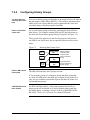
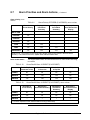
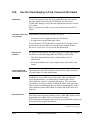
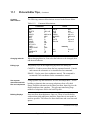
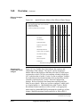
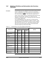
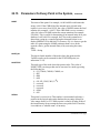
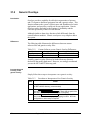
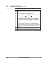
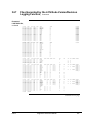
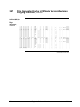
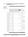
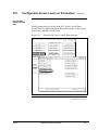
Download Engineer`s Reference Manual

Transcript
Engineer’s Reference
Manual
SW09-605
Implementation
Startup & Reconfiguration - 2
Engineer’s Reference
Manual
SW09-605
Release 650
06/04
Notices and Trademarks
Copyright 2003-2004 by Honeywell International Inc.
Revision 4 June 1, 2004
While this information is presented in good faith and believed to be accurate, Honeywell disclaims the implied
warranties of merchantability and fitness for a particular purpose and makes no express warranties except as may
be stated in its written agreement with and for its customers.
In no event is Honeywell liable to anyone for any indirect, special or consequential damages. The information and
specifications in this document are subject to change without notice.
Honeywell and TotalPlant are registered trademarks of Honeywell International Inc.
Other brand or product names are trademarks of their respective owners.
Contacts
World Wide Web
The following Honeywell Web sites may be of interest to Industry Solutions customers.
Honeywell Organization
WWW Address (URL)
Corporate
http://www.honeywell.com
Industry Solutions
http://www.acs.honeywell.com
International
http://content.honeywell.com/global/
Telephone
Contact us by telephone at the numbers listed below.
Organization
Phone Number
United States and
Canada
Honeywell International Inc.
Industry Solutions
1-800-343-0228
1-800-525-7439
1-800-822-7673
Asia Pacific
Honeywell Asia Pacific Inc.
Hong Kong
(852) 23 31 9133
Europe
Honeywell PACE, Brussels, Belgium
[32-2] 728-2711
Latin America
Honeywell International Inc.
Sunrise, Florida U.S.A.
(954) 845-2600
Sales
Service
Technical Support
Honeywell International
Process Solutions
2500 West Union Hills Drive
Phoenix, AZ 85027
1-800 343-0228
ii
Engineer’s Reference Manual
06/04
About This Publication
This Engineer's Reference Manual provides a general guide to the process engineer's
configuration, startup, and reconfiguration efforts for TPN-based TotalPlant Solution (TPS)
systems. The information presented defines how the various types of configuration data
interact, and how the interaction affects the system as seen by the process engineer as the
system operates.
If you are unsure of the terminology used in this and other implementation publications, refer
to Section 19.
The mentions in this manual of "Universal Station" or "US" also apply to Universal Work
Stations, unless otherwise defined.
This publication supports TotalPlant Solution (TPS) system network Release 650. TPS is the
evolution of TDC 3000X.
Several sections in this manual are designated as “Reserved.” In earlier versions of this
Engineer’s Reference Manual, these sections contained information that was moved to new
publications during the R400 bookset update. The following are the sections and the new
publications:
•
Sections 8 and 26
•
•
Section 9
Section 16
•
Sections 24, 25, and 29
06/04
Refer to Hiway Gateway Implementation
Guidelines.
Refer to Data Entity Builder Manual.
Refer to Application Module Implementation
Guidelines.
Refer to LCN Guidelines - Implementation,
Troubleshooting, and Service.
Engineer’s Reference Manual
iii
iv
Engineer’s Reference Manual
06/04
Table of Contents
SECTION 1 – ENGINEER’S REFERENCE MANUAL SUMMARY ..................................15
1.1
1.2
1.3
1.4
Things to Decide Before Configuring or Reconfiguring........................................ 17
Preferred Hardware Configuration ........................................................................ 20
Universal Personality & Operator Personality....................................................... 21
Section Summaries ................................................................................................ 22
SECTION 2 – FILE SYSTEM OPERATIONS ..................................................................27
2.0
2.1
2.1.1
2.2
2.3
2.4
2.5
2.5.1
2.6
Overview ............................................................................................................... 27
File System Pathnames .......................................................................................... 28
Pathname Rules ..................................................................................................... 29
Access to Volumes and Directories ....................................................................... 31
System Volumes and User Volumes...................................................................... 32
Typical File System Utility Commands ................................................................. 34
File Names and Suffixes ........................................................................................ 36
File Name Suffixes (Extensions) ........................................................................... 37
Cartridge Part Numbers ......................................................................................... 38
SECTION 3 – THE &ASY SYSTEM DIRECTORY AND ITS SPECIAL
CHARACTERISTICS..................................................................................41
3.0
3.1
3.2
Overview ............................................................................................................... 41
&ASY’s Role in Node Loading and Startup.......................................................... 42
Tools for Maintaining Backup Copies of &ASY................................................... 44
SECTION 4 – AREA (&D01-&D10) AND STANDARD ABSTRACT (&DSY)
DIRECTORIES ...........................................................................................45
4.0
4.1
4.1.1
4.2
Overview ............................................................................................................... 45
The Role of &DSY and Other Data in Loading USs ............................................. 46
The Fast-Load Feature........................................................................................... 47
Changes to Area Database, Schematics, and Button Configuration....................... 48
SECTION 5 – CONSOLE ORGANIZATION .....................................................................49
5.0
5.1
5.2
5.3
Overview ............................................................................................................... 49
Console Hints and Tips.......................................................................................... 50
Printer Failover ...................................................................................................... 51
Personality Hints and Tips..................................................................................... 53
SECTION 6 – NETWORK CONFIGURATION FILE.........................................................55
6.0
6.1
Overview ............................................................................................................... 55
NCF Information ................................................................................................... 56
SECTION 7 – HM CONFIGURATION AND USE..............................................................59
7.0
7.1
7.1.1
7.1.2
7.2
7.2.1
7.2.2
7.2.3
7.2.4
7.2.5
7.2.6
06/04
Overview ............................................................................................................... 59
Introduction ........................................................................................................... 60
HM Options and Variations................................................................................... 60
Overview of HM Operation ................................................................................... 62
Guidelines for Use of HM Storage Space.............................................................. 63
Volumes and Types of Data Stored in HMs .......................................................... 63
Allocating HM Functions on the LCN................................................................... 65
Assigning Units to HMs......................................................................................... 70
Configuring History Groups .................................................................................. 71
Requesting History through the LCN..................................................................... 72
Managing History Collection by Computers through the CG ................................ 73
Engineer’s Reference Manual
v
Table of Contents
7.3
7.3.1
7.3.2
7.3.3
7.3.4
7.3.5
7.4
7.4.1
7.4.2
7.4.3
7.4.4
7.5
7.5.1
7.5.2
7.5.3
7.5.4
7.6
7.6.1
7.7
7.7.1
7.7.2
7.7.3
7.8
7.9
Continuous History Configuration..........................................................................74
Hourly, Shift, Daily, and Monthly Averages ..........................................................75
Snapshots and User Averages.................................................................................76
Uses of Continuous History....................................................................................79
Continuous History Configuration Forms and Displays .........................................80
Continuous History Notes and Precautions ............................................................81
How to Estimate HM Volume Sizes.......................................................................83
Use of Tables and Charts to Estimate HM Volume Sizes ......................................85
HM Volume Configuration Example .....................................................................89
Applying Volume-Size Estimates to Forms and Data Entry...................................90
HM Volume Size Estimator Tables and Figures ....................................................92
Redundant HM Disk Option.................................................................................120
Configuring Redundant HM Disk Drives .............................................................123
Synchronizing Redundant HM Disk Drives .........................................................124
Setting a Redundant HM Disk Drive Off-Line.....................................................125
Servicing Redundant HM Disk Drives .................................................................126
HM Initialization ..................................................................................................127
Local HM Network Volume Configuration File, Lnp_NVCF.MM......................128
How to Save and Restore Continuous History .....................................................129
Prerequisites for Saving and Restoring Continuous History.................................129
Procedure for Saving and Restoring Continuous History.....................................130
Restoring the HM Group Definition Files (APL) without the Continuous
History Data .........................................................................................................135
HM Backup Tool Option Using the AM ..............................................................140
History Module Fragmentation ............................................................................141
SECTION 8 – ALARM MANAGEMENT ......................................................................... 143
8.0
8.1
8.2
8.2.1
8.3
8.4
8.5
8.6
8.7
8.8
8.8.1
8.8.2
8.8.3
8.8.4
8.8.5
8.8.6
8.8.7
8.8.7
8.8.7
8.8.8
8.8.9
Overview ..............................................................................................................143
Introduction ..........................................................................................................144
Release 500 Alarm Differences............................................................................145
Release 520 Alarm Enhancements .......................................................................149
Contact Cutout Basics ..........................................................................................150
Contact Cutout - R500..........................................................................................152
Contact Cutout - Display Changes........................................................................154
Contact Cutout - Functions for the HG, NIM, and AM........................................159
Alarm Priorities and Alarm Actions .....................................................................163
PRIMMOD Alarm Groups ...................................................................................166
Configure a PRIMMOD Point..............................................................................167
Link Points in the Alarm Group to the PRIMMOD .............................................169
Rules For Referencing the PRIMMOD Point.......................................................171
Retrieving Events for a PRIMMOD Group..........................................................173
Alarm Annunciation Using PRIMMOD Groups ..................................................175
Using Multiple PRIMMODs for AM Alarms.......................................................176
Using Auxiliary Units ($AUXUNIT) ...................................................................177
Using Auxiliary Units ($AUXUNIT) ...................................................................178
Using Auxiliary Units ($AUXUNIT) ...................................................................179
Other R520 Alarm Enhancements ........................................................................180
R610 Alarm Summary Enhancement ...................................................................183
SECTION 9 – DATA ENTITY BUILDER OPERATIONS ............................................... 185
9.0
Reserved...............................................................................................................185
SECTION 10 – NATIVE WINDOW SYSTEM PERFORMANCE DISPLAYS ................. 187
vi
Engineer’s Reference Manual
06/04
Table of Contents
10.0
10.1
10.2
10.2.1
10.3
10.4
10.5
10.6
10.7
Overview ............................................................................................................. 187
Preface ................................................................................................................. 188
How to Install the System Performance Displays ................................................ 189
Table of Current TLK1 Versions......................................................................... 190
How to Call Up the System Performance Displays.............................................. 192
The Displays and Their Content ........................................................................ 193
How to Interpret the Information on the System Performance Displays.............. 200
Use the Clock Display to Find Crossed LCN Cables........................................... 205
Use the Channel Information Display to Monitor TPS/TPN Channel Activity ... 208
SECTION 11 – SCHEMATIC FILES ...............................................................................211
11.0
11.1
Overview ............................................................................................................. 211
Picture Editor Tips............................................................................................... 212
SECTION 12 – CONTROL LANGUAGE FILES .............................................................219
12.0
12.1
Overview ............................................................................................................. 219
File Handling Tips ............................................................................................... 220
SECTION 13 – AREA DATABASE, CONTENT, AND USE............................................223
13.0
13.1
13.2
13.3
Overview ............................................................................................................. 223
Database Composition ......................................................................................... 224
Assigning Units to an Area .................................................................................. 226
Adding a New Volume or Directory to the Pathname Catalog ............................ 227
SECTION 14 – DATA BINDING IN THE TPS SYSTEM .................................................231
14.0
14.1
14.2
14.3
14.4
14.5
14.6
14.7
Overview ............................................................................................................. 231
Binding of Unit, Area, and Console Names......................................................... 235
Binding of NCF Data........................................................................................... 237
Binding of HM Local NVCF Data....................................................................... 238
Binding of Entity Data in the Data Entity Builder ............................................... 239
Binding of Schematic Data .................................................................................. 241
Binding of Data in CL Programs ......................................................................... 242
Binding of Entities and Schematics into the Area Database ................................ 243
SECTION 15 – ACTORS AND PROCESS CONTROL ..................................................245
15.0
15.1
Overview ............................................................................................................. 245
Use of Actors ....................................................................................................... 245
SECTION 16 – AM CONFIGURATION GUIDELINES....................................................247
16.0
Reserved .............................................................................................................. 247
SECTION 17 – DATA TO BE USED DURING CONFIGURATION ................................249
17.0
17.1
Overview ............................................................................................................. 249
Publications Defining Configuration Data........................................................... 250
SECTION 18 – AVOIDING MISTAKES AND ERRORS .................................................251
18.0
18.1
Overview ............................................................................................................. 251
Guidelines and Warnings..................................................................................... 251
SECTION 19 – GLOSSARY OF TPS CONFIGURATION TERMS ................................257
19.0
19.1
06/04
Overview ............................................................................................................. 257
Configuration Terms............................................................................................ 257
Engineer’s Reference Manual
vii
Table of Contents
SECTION 20 – NODE LOADING AND NODE DUMPS................................................. 263
20.0
20.1
20.2
20.2.1
20.2.2
20.2.3
20.2.4
20.3
20.3.1
Overview ..............................................................................................................263
Node Loading Failures .........................................................................................264
Fast-Load Feature.................................................................................................267
Fast-Load Scenario...............................................................................................269
Fast-Load Implementation Considerations and Guidelines ..................................271
Content and Maintenance of Fast-Load Cartridges ..............................................274
How to Prepare or Update a Fast-Load Cartridge ................................................277
Node Dumps.........................................................................................................287
Dump Failures ......................................................................................................287
SECTION 21 – CHECKPOINTING................................................................................ 289
21.0
21.1
21.2
21.2.1
21.2.2
21.2.3
21.2.4
21.3
21.3.1
21.3.2
Overview ..............................................................................................................289
How to Configure for Checkpointing ...................................................................291
Checkpoint Functions...........................................................................................293
Demanding, Enabling, and Disabling Checkpoints ..............................................293
Automatic Checkpointing.....................................................................................295
Levels of Automatic Checkpointing .....................................................................300
Checkpoint File Organization...............................................................................302
Checkpoint Error Messages..................................................................................305
System Error Messages—Hiway Checkpoint.......................................................306
System Error Messages—UCN Auto Checkpoint ................................................307
SECTION 22 – PROCESSOR STATUS DATA POINT................................................. 309
22.0
22.1
22.2
22.3
22.4
22.5
22.6
22.7
22.8
22.9
22.10
22.11
22.12
22.13
22.14
22.15
Overview ..............................................................................................................309
Purpose of Processor Status Data Points ..............................................................310
PSDP Parameters in All Nodes ............................................................................311
Application Module PSDP Parameters ................................................................319
Computer Gateway PSDP Parameters..................................................................338
History Module PSDP Parameters .......................................................................343
Hiway Gateway PSDP Parameters .......................................................................347
Network Gateway PSDP Parameters....................................................................351
Universal Station PSDP Parameters .....................................................................358
HM60 PSDP Parameters ......................................................................................366
Remote User Link Adapter (RULA) PSDP Parameters .......................................367
Network Interface Module PSDP Parameters .....................................................368
Application Processing Platform PSDP Parameters.............................................370
Global User Station PSDP Parameters .................................................................372
Unit Operations Data Point ..................................................................................373
Parameters On Every Point in the System ............................................................374
SECTION 23 – CONFIGURING FOR PERFORMANCE .............................................. 381
23.0
23.1
23.1.2
23.2
23.3
23.4
23.5
23.6
23.6.1
23.6.2
23.6.3
viii
Overview ..............................................................................................................381
The Performance Cluster Concept........................................................................382
Cluster Performance (68020-Based Processors) ..................................................385
The Honeywell Control Unit ................................................................................388
Focused Load Concept .........................................................................................391
Factors that Affect System Performance ..............................................................392
Estimating LCN Load on Your System ................................................................394
HM Performance Hints and Rules of Thumb .......................................................397
HM Utilization .....................................................................................................398
Continuous History Hints and Rules of Thumb....................................................399
Fast Search User Volume .....................................................................................400
Engineer’s Reference Manual
06/04
Table of Contents
23.6.4
23.6.5
Directory Searches Hints and Rules of Thumb .................................................... 401
Event Journal Hints and Rules of Thumb ............................................................ 403
SECTION 24 – NCF AND LCN STATUS DISPLAYS ....................................................405
24.0
Reserved .............................................................................................................. 405
SECTION 25 – LCN RECONNECTION .........................................................................407
25.0
Reserved .............................................................................................................. 407
SECTION 26 – LCN/DATA HIWAY HARDWARE COMPATIBILITY ............................409
26.0
Reserved .............................................................................................................. 409
SECTION 27 – HOW TO MOVE TO A NEW TPS RELEASE .......................................411
27.0
27.1
27.2
27.2.1
27.2.2
Overview ............................................................................................................. 411
What is a .............................................................................................................. 411
Upgrading Software............................................................................................. 412
The Software Upgrade Process............................................................................ 413
Preparation for a Software Upgrade .................................................................... 414
SECTION 28 – PURCHASED OPTIONS .......................................................................415
28.0
28.1
28.1.1
28.1.2
28.1.3
28.1.4
28.2
28.2.1
28.2.2
28.2.3
28.2.4
28.2.5
28.2.6
28.2.6.1
28.2.6.2
28.2.6.3
28.2.6.4
28.2.6.5
28.2.6.6
28.2.6.7
28.2.7
28.2.8
28.2.9
28.2.10
28.2.11
28.2.12
Overview ............................................................................................................. 415
Key File Options.................................................................................................. 417
AM Redundancy.................................................................................................. 418
HG Point Display Ranges .................................................................................... 420
Enhanced Trend Pens .......................................................................................... 421
HM Disk Redundancy ......................................................................................... 422
Hardware Options................................................................................................ 424
Application Module Hardware Upgrades ............................................................ 426
Enhanced (68040) Computer Gateway ................................................................ 428
Computer Gateway to Plant Network Module Upgrade ..................................... 429
Programmable Logic Controller Gateway Upgrades ........................................... 430
Enhanced (68040) Hiway Gateways.................................................................... 431
Universal Station and Workstation Upgrades ...................................................... 432
Cartridge Drive Upgrades.................................................................................... 433
Improved Display Screen Upgrades .................................................................... 434
Enhanced Processor or Memory Upgrades.......................................................... 435
Printer Enhancement Upgrades............................................................................ 436
Touch Screen Upgrade ........................................................................................ 437
Keylock Switch Replacement Upgrade................................................................ 438
Keyboard Addition Upgrades .............................................................................. 439
HM Upgrades ...................................................................................................... 440
Time-Sync Upgrades for Network Interface Module........................................... 442
Precision Clock Sources ...................................................................................... 443
Process Manager to Advanced Process Manager Upgrades ................................ 444
LCN Extender...................................................................................................... 445
Micro TDC 3000 Upgrades ................................................................................. 446
SECTION 29 – LCN CABLE DIAGNOSIS .....................................................................449
29.0
Reserved .............................................................................................................. 449
SECTION 30 – EVENT-INITIATED REPORTS—IMPLEMENTATION AND USE ........451
30.0
30.1
06/04
Overview ............................................................................................................. 451
Implementation of Event-Initiated Reports.......................................................... 452
Engineer’s Reference Manual
ix
Table of Contents
30.1.1
30.1.2
30.1.3
30.2
30.2.1
Message-Source Considerations...........................................................................453
Area Reports.........................................................................................................454
Event History Reports ..........................................................................................457
Operation of Event-Initiated Reports ...................................................................462
Error Handling .....................................................................................................463
SECTION 31 – CUSTOM SOFTWARE BACKPLANE AND GENERIC OVERLAYS ... 465
31.0
31.1
31.1.1
31.1.2
31.2
Overview ..............................................................................................................465
Custom Software Installation ...............................................................................466
The NET>&CUS Directory..................................................................................467
Using the LCN Node Configuration Menu...........................................................468
Generic Overlays..................................................................................................470
SECTION 32 – REPORT TO OUTPUT FILE ................................................................. 471
32.0
32.1
32.2
32.3
32.4
32.5
32.6
32.7
32.8
Overview ..............................................................................................................471
Virtual Printer Assignments .................................................................................472
Setting Up a Configuration File............................................................................474
Sending Reports to a Virtual Printer File .............................................................476
Using File Descriptors to Identify Virtual Printer Files........................................477
Displaying and Printing Reports...........................................................................478
Status and Error Messages ...................................................................................479
Error Handling .....................................................................................................482
Purging and Protecting Virtual Printer Files ........................................................485
SECTION 33 – KEYBOARD BUTTON LED ASSIGNMENT AND CONTROL ............. 487
33.0
33.1
33.1.1
33.1.2
33.1.3
33.1.4
Overview ..............................................................................................................487
Implementation.....................................................................................................488
Message-Source Considerations...........................................................................489
Button PRIMMOD Assignment ...........................................................................490
Button LED Control .............................................................................................492
Error Handling .....................................................................................................494
SECTION 34 – LCN NODE VERSION REVISION LOGGING....................................... 495
34.0
34.1
34.2
34.3
34.4
34.5
34.6
34.7
34.8
34.9
Overview ..............................................................................................................495
General Functionality ...........................................................................................496
Requirements........................................................................................................502
Installation Requirements .....................................................................................504
Initial (First Time) Installation .............................................................................506
Upgrade Installation .............................................................................................510
Operating the LCN Node Version/Revision Logging Function............................512
Files Generated by the LCN Node Version/Revision Logging Function..............529
Error Conditions...................................................................................................537
Importing Report File into Spreadsheet................................................................540
SECTION 35 – R530 TREND AND OPERATING DISPLAY FUNCTIONS ................... 541
35.0
35.1
35.2
35.3
35.4
35.5
x
Overview ..............................................................................................................541
Configurable Access Levels on Parameters..........................................................542
One Key Call Up of Point Trend..........................................................................548
Save/Restore Trend Data......................................................................................550
Detail Display Navigation ....................................................................................556
SP/OP Tolerance Check .......................................................................................557
Engineer’s Reference Manual
06/04
Table of Contents
SECTION 36 – R610 PERIODIC PRE-DEFINED DOCUMENTATION TOOL
QUERY .....................................................................................................559
36.0
36.1
36.2
06/04
Overview ............................................................................................................. 559
Implementation .................................................................................................... 560
Periodic Pre-Defined Query Scenarios ................................................................ 566
Engineer’s Reference Manual
xi
Table of Contents
Figures
Figure 1-1
Figure 7-1
Figure 7-2
Figure 7-3
Figure 7-4
Figure 7-5
Figure 7-6
Figure 7-7
Figure 7-8
Figure 7-9
Figure 7-10
Figure 7-11
Figure 7-12
Figure 7-13
Figure 8-1
Figure 8-2
Figure 8-3
Figure 8-4
Figure 8-5
Figure 8-6
Figure 10-1
Figure 11-1
Figure 13-1
Figure 14-1
Figure 14-2
Figure 31-1
Figure 34-1
Figure 34-2
Figure 34-3
Figure 34-4
Figure 34-5
Figure 34-6
Figure 34-7
Figure 34-8
Figure 34-9
Figure 34-10
Figure 34-11
Figure 34-12
Figure 34-13
Figure 35-1
Figure 35-2
Figure 35-3
Figure 35-4
xii
Representative TPS Hardware................................................................................20
Reducing Data Owner Load ...................................................................................71
Continuous History Structure.ii.Snapshots and User Averages..............................78
Area Volume Size Estimator Chart ......................................................................110
AM Checkpoint Volume Size Estimator Chart ....................................................111
NIM/PM Checkpoint Volume Size Estimator Chart ............................................112
NIM Checkpoint Volume Size Estimator Chart, 1 NIM ......................................113
NIM/LM Checkpoint Volume Size Estimator Chart, 1 to 32 LMs.......................114
NIM/APM Checkpoint Volume Size Estimator Chart .........................................115
Continuous History Vol. Size, Example 1............................................................116
Continuous History Vol. Size, Example 2............................................................117
Journal Volume Size Chart, Example 1................................................................118
Journal Volume Size Chart, Example 2................................................................119
Physical Arrangement of Redundant Disk Drives ................................................121
Primary Module Point Example ...........................................................................168
PRIMMOD Parameter in PED .............................................................................169
Point Detail Display with PRIMMOD Parameter ................................................170
Event History Retrieval by PRIMMOD ...............................................................173
Example of PRIMMOD Event History ................................................................174
PRIMMOD Alarm Annunciation .........................................................................175
Parameter-access load values relationships ..........................................................203
Picture Editor File Relationships..........................................................................213
Unit Assignment Picks and Unit Annunciator Picks ............................................226
Quick Reference Matrix of the Effects of Data Changes......................................233
Configuration Sequences and Data Relationships ................................................234
LCN Node Configuration Menu...........................................................................468
LCN Node Version/Revision Logging Display....................................................512
LCN Node Version/Revision Logging Display (with...........................................513
LCN Node Version/Revision Logging Display (with Site ID) .............................514
LCN Node Version/Revision Logging Display (with...........................................515
LCN Node Version/Revision Logging Display (with LCN ID) ...........................516
LCN Node Version/Revision Logging Display (with Report Generation
Status) ...............................................................................................................520
LCN Node Version/Revision Logging Display (with Report Generation In
Progress) ...........................................................................................................521
LCN Node Version/Revision Logging Display (with Report Generation
Complete or Failure).........................................................................................522
Generated Report - Leftmost 80 Characters .........................................................523
Generated Report - Rightmost 80 Characters .......................................................524
LCN Node Version/Revision Logging Display (Printer Number data entry
port) ..................................................................................................................526
LCN Node Version/Revision Logging Display (Printer Number in the ...............527
LCN Node Version/Revision Logging Display (with a failure status) .................537
System Wide Value, Console Data Selection.......................................................545
System Wide Values, NCF Console Data PAGE 5 with Configurable Access
Level on Parameters Information......................................................................546
Saved Trend Data File..........................................................................................551
Connection Page in Detail Display with Connection............................................556
Engineer’s Reference Manual
06/04
Table of Contents
Tables
Table 1-1
Table 2-1
Table 2-2
Table 2-3
Table 5-1
Table 7-1
Table 7-2
Table 7-3
Table 7-4
Table 7-5
Table 7-6
Table 7-7
Table 7-8
Table 7-9
Table 7-10
Table 7-11
Table 7-12
Table 7-13
Table 7-14
Table 7-15
Table 7-16
Table 7-17
Table 7-18
Table 7-19
Table 7-20
Table 7-21
Table 8-1
Table 8-2
Table 8-3
Table 8-4
Table 8-5
Table 8-6
Table 8-7
Table 8-8
Table 8-9
Table 8-10
Table 10-1
Table 10-2
Table 10-3
Table 10-4
Table 10-5
Table 10-6
Table 10-7
Table 10-8
Table 10-9
Table 10-10
Table 10-11
Table 10-12
Table 10-13
Table 10-14
Table 10-15
Table 11-1
06/04
Displays and Functions Accessed through Targets and Keys ................................ 21
System Volumes .................................................................................................... 33
Abbreviations......................................................................................................... 34
Suffixes.................................................................................................................. 37
Format of Printer Failover Text File...................................................................... 51
HM Data Types ..................................................................................................... 64
Rates at which Snapshots (SS) are Collected......................................................... 76
Estimated Number of Cartridges to Fill an HM..................................................... 84
Tables Used to Estimate HM Volume Size ........................................................... 87
List of Volume-Size Charts in Section 7................................................................ 88
Summary of Variable Data used in Example ......................................................... 89
Example Memory Required vs. Drive Capacity .................................................... 89
Picks on Volume Configuration Menu .................................................................. 90
HM Volume Size Estimator................................................................................... 92
HM User Volume or Directory Size Estimator.................................................... 101
IDF Volume or Directory Size Estimator ............................................................ 102
Example—Small System, One Area, One Cluster ............................................... 103
Example—IDF Volume Estimate (approximately 5 HCUs) ................................ 105
Example—User Volumes, Small System, One Cluster, One Dual HM ............... 106
Value Sources for Volume Configuration............................................................ 107
Disk Drive Options .............................................................................................. 123
NCF Configuration Items That Can’t Be Changed .............................................. 129
Saving and Restoring Continuous History ........................................................... 130
Restoring HM Group Configuration without History .......................................... 135
Preparing to Overcoming History Module Fragmentation................................... 141
Procedure for Overcoming HM Fragmentation ................................................... 142
New Functionality Table...................................................................................... 144
Contact Cutout Changes in R500......................................................................... 151
Contact Cutout Scenario Overview...................................................................... 155
Contact Cutout Alarm Summary Display Changes .............................................. 156
HG Contact Cutout Functionality ........................................................................ 160
NIM Contact Cutout Functionality ...................................................................... 161
AM Contact Cutout Functionality........................................................................ 162
Alarm Priority Choices ........................................................................................ 163
Alarm Priority XXXXPR (E ALPRIOR)............................................................. 163
Alarm Enable State ALENBST (E ALENBST) .................................................. 164
Procedures for Installing and Using the Displays ................................................ 188
Procedure to Call Up a Performance Display ...................................................... 192
Node-Related Displays ........................................................................................ 196
Quick Trend Display............................................................................................ 197
Processor Free-Time Display............................................................................... 197
Heap Displays...................................................................................................... 198
Checkpoint Time and Interval Display ................................................................ 198
Box/Slot Verification Display.............................................................................. 198
Clock (CLOKSTAT) Displays ............................................................................ 199
Memory-Use Values ............................................................................................ 201
Processor Load Indicator ..................................................................................... 201
Memory-Use Values ............................................................................................ 202
Checking Procedure for Crossed LCN Cables..................................................... 206
Displaying Channel Information for a Node........................................................ 209
CHANINFO Display Definitions......................................................................... 210
Color Priority....................................................................................................... 214
Engineer’s Reference Manual
xiii
Table of Contents
Table 11-2
Table 13-1
Table 13-2
Table 13-3
Table 13-4
Table 13-5
Table 14-1
Table 14-2
Table 14-3
Table 14-4
Table 14-5
Table 14-6
Table 14-7
Table 18-1
Table 18-2
Table 20-1
Table 20-2
Table 20-3
Table 20-4
Table 20-5
Table 20-6
Table 30-1
Table 30-2
Table 30-3
Table 31-1
Table 31-2
Table 31-3
Table 32-1
Table 32-2
Table 32-3
Table 32-4
Table 32-5
Table 32-6
Table 34-1
Table 34-2
Table 34-3
Table 34-4
Table 34-5
Table 34-6
Table 34-7
Table 34-8
Table 34-9
Table 34-10
Table 34-11
Table 34-12
Table 34-13
Table 34-14
xiv
Common Abbreviations........................................................................................216
Displays Available ...............................................................................................227
Methods of Accessing a Volume or Directory .....................................................228
Procedure for Copying Files to an HM ................................................................228
Adding a Pathname to an HM or to a Cartridge ...................................................229
Making an Area Change .......................................................................................230
Summary of Data Binding in the TPS System......................................................232
Detailed Matrix of NCF Data Binding Relationships...........................................237
Detailed Matrix of NVCF Data Binding Relationships........................................238
Detailed Matrix of DEB Data Binding Relationships ..........................................239
Detailed Matrix of NCF Schematic Data Binding Relationships .........................241
Detailed Matrix of NCF CL Data Binding Relationships.....................................242
Detailed Matrix of Area Data Binding Relationships...........................................243
Database Loading and Checkpointing Rules ........................................................252
Procedure Used When Moving the System Volume (&ASY)..............................253
Interpreting Cause of Node ..................................................................................265
Clearing a LOAD FAIL (from the System Status Display) ..................................265
Clearing a LOAD FAIL message (from the Console, Process Network Node,
or Device Node Status Displays) ......................................................................266
Loading a US from Itself......................................................................................269
Stages of the Cartridge Fast-Load Scenario .........................................................270
Display Abstracts Loaded First ............................................................................271
$AREA and $CONS Information.........................................................................454
The Item Parameter ..............................................................................................457
Date and Time Parameter .....................................................................................458
Installation Steps ..................................................................................................466
Custom Software vs. Generic Overlay Differences ..............................................470
Procedure to Incorporate a New Generic Overlay................................................470
Virtual Printer Assignment One Area Example....................................................473
Virtual Printer Assignment Two Area Example ...................................................473
VP CONFIG Error Messages ...............................................................................481
SYStem Error Handling Process ..........................................................................482
USER Error Handling Process .............................................................................483
SEVERE Status Handling Procedure ...................................................................483
LCN Node, Board Description Header Record ....................................................498
Data Hiway Box, Card Description Header Record .............................................499
UCN Node, Card Description Header Record .....................................................499
LCN Nodes Reported ...........................................................................................500
Data Hiway Boxes Reported ................................................................................501
UCN Nodes Reported...........................................................................................501
Dedicated Custom Global DDB Indices...............................................................503
Find a Directory ...................................................................................................505
Universal Station Configuration ...........................................................................507
Loading the Node .................................................................................................511
Call Up LCN Node Version/Revision Logging Display.......................................512
Open Site ID Data Entry Port...............................................................................513
Open LCN ID Data Entry Port .............................................................................515
LCN Node Version/Revision Logging Display....................................................539
Engineer’s Reference Manual
06/04
Section 1 – Engineer’s Reference Manual Summary
1.0
Overview
Introduction
This section introduces you to this publication and summarizes the
content of its remaining sections.
References
Detailed actions and procedures are described in other publications
and we assume that you have had some exposure to the TotalPlant
Solution (TPS) System concepts.
For overviews and summaries of the implementation processes:
• see System Overview, or
• see Implementation Overview, or
• see Configuration Data Collection Guide.
Supplement to other
publications
This publication supplements the detailed publications and is
intended to help you to:
PLAN AHEAD!
PLAN AHEAD!
PLAN AHEAD!
PLAN AHEAD!
by showing interactions and relationships in the engineering activities
and the system, and the effects of configuration or configuration
changes.
Start by making a complete backup set of all Zip disks provided with
the system. Refer to Section 2 for use of the Create Volume and
FCOPY commands that are used to do this.
System Software
System software is delivered on Zip disks or CD-ROMs. See System
Startup Guide-CD-ROM when using a GUS.
Continued on next page
06/04
Engineer’s Reference Manual
15
1.0
Overview,
Relationship to other
publications
Continued
For startup information, refer to the System Startup Guide.
For engineers who are implementing a new LCN-based system, this
publication is keyed to the startup guide by a “[TASK nn]” identifier
on several of its headings. These system startup tasks are identified in
the table of contents of the startup guide.
This publication also is directed to engineers who are redesigning and
reconfiguring LCN-based TPS systems.
16
Engineer’s Reference Manual
06/04
1.1
Things to Decide Before Configuring or
Reconfiguring
Where to begin
Before configuring or reconfiguring your system, refer to Section 14
on data binding and consider which configuration changes can be
made on-line after an NCF has been installed and is in use. You may
want to defer some inconvenient tasks to another time.
Understand concepts
You should understand the following concepts.
• Organization of the plant into units and areas.
• Area assignments to consoles.
• Number and sizes of HM user volumes and directories (refer to
Section 2 and Section 7).
• Naming and numbering conventions.
Naming and
numbering
conventions
For naming and numbering conventions, consult these references.
• For Units, Areas, and Consoles, see Network Form Instructions.
• For HM User Volumes, see Section 7 of this publication.
• For Logs, Groups, and Overview Displays, see Area Form
Instructions.
Parameter information
Each major TPS device has an appropriate parameter reference
dictionary. For specific parameter information:
• see Hiway Gateway Parameter Reference Dictionary, or
• see PM Family Parameter Reference Dictionary, or
• see Computer Gateway Parameter Reference Dictionary, or
• see Logic Manager Parameter Reference Dictionary, or
• see Programmable Logic Controller Gateway Parameter Reference
Dictionary.
Continued on next page
06/04
Engineer’s Reference Manual
17
1.1
Things to Decide Before Configuring or
Reconfiguring, Continued
File conventions
Consult these references for file and custom data segment
conventions.
• For IDFs (entity files) and Exception Build Files, see the Data
Entity Builder Manual.
• For Subpicture and Schematic Files, see the Picture Editor Data
Entry.
• For CL Program Source Files and Custom Data Segments:
– see Control Language/Multifunction Controller Data Entry, or
– see Control Language/Application Module Data Entry, or
– see Control Language/Process Manager Data Entry, or
– see Control Language/Advanced Process Manager Data Entry.
Recommended
hardware and
personality
We recommend (and assume) that for your work you will use a
Universal Station or a Universal Workstation loaded with the
Universal Personality. This Universal Personality software contains
both Engineering functions and the Operator functions.
Your Universal Station should also have two Zip drives and a printer
connected directly to the US.
Why this
arrangement?
This arrangement provides Zip disk operations that are faster than if
the drive is connected to another US in the console, and it enables
screen printing.
You can also switch quickly from Engineering functions to the
Operator functions to see the results of your work as you enter data
and load it in the nodes.
Load another US with
Operator Personality
functions
So you can see the results of your work, it’s helpful to have another
US in the same console loaded with the Operator Personality
functions.
Continued on next page
18
Engineer’s Reference Manual
06/04
1.1
Things to Decide Before Configuring or
Reconfiguring, Continued
Conceptual
organization
Figure 1-1 shows the conceptual organization of the hardware on a
TPS system. The following are special items to be noted from this
diagram:
• A process area is a portion of the process plant normally controlled
by one operator.
• A process unit is a specific section of the plant (such as a boiler,
furnace, or blender).
• A console is a logical collection of Universal Stations and their
associated peripherals for use by one operator. A console is
associated with one process area, and the area database configured
for that area is to be loaded into each US in the console when the
USs are loaded.
• Peripherals on a console are physically connected to only one
Universal Station; however, they are generally available for use by
other Universal Stations within the console, provided the Universal
Station to which they are connected is operating on the LCN.
• Mass-storage access—The LCN is connected into the HM, not
directly to the Winchester drives. Access to the Winchester disks
by the LCN is possible only when the HM is operating on the LCN.
Continued on next page
06/04
Engineer’s Reference Manual
19
1.1
Figure 1-1
Things to Decide Before Configuring or
Reconfiguring, Continued
Representative TPS Hardware
Console
CM
AM
HM
CG
HG
Process-Connected
Boxes
Data Hiway
NIM
NIM
HG
Logic
Managers
Process
Managers
Universal Control
Network
1223
1.2
Preferred Hardware Configuration
Refer to Section 23—Configuration for Performance.
20
Engineer’s Reference Manual
06/04
1.3
Universal Personality and Operator Personality
The meaning of
“Personality” in this
manual
In the Universal Station, we refer to the Universal Personality and the
Operator Personality. For Universal Stations (USs) and Universal
Work Stations (UWSs) operating on the Universal Personality (UP),
these mentions mean the portion of the Universal Personality that
contains all Engineering functions and all Operator functions. The
Operator Personality refers only to the Operator functions in the USs
and UWSs.
Differences between
functions
The Engineering functions are those that are activated by targets
(called “picks”) on the Engineering Main Menu. Most other
functions are Operator functions, however, there are several displays
and functions that are shared by both the Engineering functions and
the Operator functions. NOTE: For R500 there is no separate
Engineering Personality to load; Engineering functions are included
with Operator functions in the Universal Personality.
Access through
targets and keys
These are the displays and functions that are accessed through the
following targets or keys:
Table 1-1
Keys
Displays and Functions Accessed through Targets and
Engineering Main Menu Targets
Operator Keyboard Keys
SYSTEM STATUS
SYST STATS
SYSTEM MENU
SYST MENU
CONSOLE STATUS
CONS STSTS
Calling functions in
the Universal
Personality
At a US running the Universal Personality, to call up the Engineering
Main Menu from any display, hold CTL and press HELP (MENU).
In some Engineering functions activities, you may need to do this
twice, either because of a prompter that warns you about possible loss
of data, or because you have to go through a lower-level menu to get
to the main menu. To go to an Operator function from an
Engineering functions activity, first return to the Engineering Main
Menu.
Memory requirement
for Universal
Personality
6Mw of memory are required in USs functions and UWSs that are to
operate using the Universal Personality.
06/04
Engineer’s Reference Manual
21
1.4
Section Summaries
Introduction
The following are summaries of the content of each of the other
sections in this manual.
Section 2—File
System Operations
The file system stores software and data on Zip disks and History
Modules (HMs). This section defines the file system concepts and
describes the most-often used Utilities commands.
Section 3—The &ASY
Directory and its
Special
Characteristics
Describes the special characteristics of system directory &ASY,
which contains the basic description files required for the startup of
each node, including the network configuration file (NCF.CF). You
need to know about these characteristics so that you can avoid
problems related to this directory or recover from them.
Section 4—Area and
Standard Abstract
Directories
Describes the special characteristics of the area database directory and
the abstract directories that define the appearance and content of the
displays in the operator's personality.
Section 5—Console
Organization
Explains how a console is defined, defines special characteristics of
the devices that can be connected to a Universal Station, and provides
some tips for optimum console performance and convenience.
Section 6—Network
Configuration File
Describes the special characteristics of the Network Configuration
File. This file contains network information that is vital for the
operation of all nodes on the LCN. The content of the NCF is
defined, as are its use in node startup. Also see Section 3—it
discusses directory &ASY, the directory that contains the NCF.
Section 7—HM
Volume Configuration
and Initialization
Defines the requirements for configuring and starting up an HM. It
also provides guidelines for use of HM storage space and for
estimating the size of the volumes assigned to each.
Section 8—Reserved
In earlier versions of this manual, this section contained Hiway, Box,
and Slot Configuration Guidelines. For this information, you must
refer to Hiway Gateway Implementation Guidelines. This section has
been retained to direct users familiar with an earlier version of this
manual to the new location of the information and to preserve the
validity of references to other sections of this manual.
Continued on next page
22
Engineer’s Reference Manual
06/04
1.4
Section Summaries,
Continued
Section 9—Reserved
Data Entity Builder Operations—In earlier versions of this manual,
this section contained guidelines for Data Entity Builder operations.
Now you must refer to the Data Entity Builder Manual. This section
has been retained to direct users familiar with an earlier version of
this manual to the new location of the information and to preserve the
validity of references to other sections of this manual.
Section 10—System
Performance Displays
Explains how to monitor and evaluate system performance through
access to the System Performance Displays. Help in interpreting the
displays is included to aid in diagnosing the cause of the problem.
Section 11—Picture
Editor and Custom
Displays
Provides tips for the use of the Picture Editor to build custom
(schematic) displays.
Section 12—Control
Language (CL)
Provides tips and precautions for the use and handling of the data and
files used in compiling, linking, and loading CL programs.
Section 13—Area
Database, Content,
and Use
Describes the content of the area database and how the area for a
console is established. It also points out that changes to the area
database actually take place in a US only when the database is loaded
into that US. The relationship of the Engineering functions Unit
Assignment display to the operator's personality's alarm summary and
annunciator displays is defined.
Section 14—Data
Binding in the
TPS System
Introduces the concept of data binding and it describes the
consequences of that binding. The effect of data binding on
configuration and reconfiguration of the system is also discussed.
Section 15—Actors
and Process Control
Advises that actors are not to be used for actions that are involved in
process control.
Section 16—Reserved
In earlier versions of this manual, this section contained AM
Configuration Guidelines. For this information, you must refer to
the Application Module Implementation Guidelines. This section has
been retained to direct users familiar with an earlier version of this
manual to the new location of the information and to preserve the
validity of references to other sections of this manual.
Continued on next page
06/04
Engineer’s Reference Manual
23
1.4
Section Summaries,
Continued
Section 17—Data to
be Used During
Configuration
Relates the types of configuration data to the publications that define
each type of data and to the configuration forms used to record each
type of data.
Section 18—Avoiding
Mistakes and Errors
Contains a collection of the significant guidelines, precautions, and
warnings that appear in this and other publications. If you review this
section from time to time, and implement its content, you should
experience a minimal amount of rework and error correction.
Section 19—Glossary
of TPS Configuration
Terms
Summarizes the terms related to the configuration process. You can
also refer to the System Overview for a more extensive glossary.
Section 20—Node
Loading Guidelines
Provides guidelines for recovering from the failure of a node to load
properly with software and data.
Section 21—
Automatic
Checkpointing
Describes how you can configure your system for automatic
checkpointing for NIMs, HGs, AMs, and CGs, how automatic
checkpointing functions, and what happens if an error occurs.
Section 22—
Processor Status Data
Point
Defines processor-status data points (PSDPs), discusses their use, and
lists each PSDP parameter with its definition.
Section 23—
Configuring for
Performance
Defines two items that are the basis for system performance
measurements and system integrity. These items are the performance
cluster concept and the Honeywell control unit (HCU). Guidelines
for configuring LCN-based equipment for predictable performance
and for estimating AM performance are provided.
Section 24—Reserved
In earlier versions of this manual, this section provided information
about displays that provided information about NCF and LCN
status. For this information, you must refer to LCN Guidelines Implementation, Troubleshooting, and Service. This section has been
retained to direct users to the new information.
Continued on next page
24
Engineer’s Reference Manual
06/04
1.4
Section Summaries,
Continued
Section 25—Reserved
In earlier versions of this manual, this section provided information
about LCN reconnection. For this information, you must refer to
LCN Guidelines - Implementation, Troubleshooting, and Service.
This section has been retained to direct users to the new information.
Section 26—Reserved
In earlier versions of this manual, this section provided information
about displays that provided information about NCF and LCN
status. For this information, you must refer to Hiway Gateway
Implementation Guidelines. This section has been retained to direct
users to the new information.
Section 27—How to
Move to a New
TPS Release
This section defines a software release and provides general
guidelines for upgrading to a new software release.
Section 28—
Purchased Options
This section describes system options available for purchase and
provides guidance and references for the implementation of the
options.
Section 29—Reserved
In earlier versions of this manual, this section provided information
about diagnosing LCN cable problems. For that information, refer
to LCN Guidelines - Implementation, Troubleshooting, and Service.
Section 30—EventInitiated Reports—
Implementation and
Use
This section provides information about the implementation and use
of printed reports whose printing is initiated by user-defined events.
Section 31—Custom
Software Backplane
and Generic Overlay
The Custom Software Backplane is a provision that allows the
addition of optional, standard, and custom software modules to a node
without modifying the node’s original personality software.
Generic Overlays enable table-driven generation of pictures and CL
sequences based on equipment lists and a generic source. This
function enhances the system’s effectiveness and friendliness for
batch applications, and provides a useful tool for any application.
Section 32—Report to
Output File
Reports can be sent to an electronic file that is a “virtual printer” to
the TPS system. The user selects the number of the “printer” the data
should go to by submitting a normal printer request.
Continued on next page
06/04
Engineer’s Reference Manual
25
1.4
Section Summaries,
Continued
Section 33—Keyboard
Button LED
Assignment and
Control
This section describes the implementation and use of CL messages to
assign primmod values to buttons and control the LEDs on specified
LED buttons associated with any of the 40 configurable LED buttons
to be dynamically changed for the local Universal Station.
Section 34—LCN Node
Version/Revision
Logging function
The LCN Node Version/Revision Logging function is a software
application package that operates on Universal Stations of the
Honeywell TPS system. This function is a TPS “backplane”
extension of the Universal Station Operator personality and Universal
personality and is packaged as an External Load Module. The
function is a display initiated version/revision report generator.
Section 35—R530
Trend and Operating
Display functions
The following R530 functions are included in this section:
• Configurable Access Level of Parameters - Access level is
configured in the NCF for alarm limits, control limits, range limits,
and tuning parameters on the Point Detail Display.
• One Key Call Up of a Point Trend - A custom trend can be invoked
by pressing the TREND key after selecting a point from a standard
display.
• Save Trend Data - Two new actors are provided to save and restore
custom schematic trend data.
• Detail Navigation - On pages of the Detail Display which contain
input, output, and control connections, targets are added over any
point names that are displayed.
• SP/OP Tolerance Check - Manually entered SP and OP values for
AM, HG, and NIM regulatory control points and OP values for HG
and NIM analog output points are checked against a specified
magnitude of change tolerance.
26
Engineer’s Reference Manual
06/04
Section 2 – File System Operations
2.0
Description
Overview
The file system stores software and data on Zip disks and History
Modules (HMs).
This section defines the file system concepts and describes the mostoften used Utilities commands.
06/04
Engineer’s Reference Manual
27
2.1
File System Pathnames
File usage
Data in the system is collected into named files that are stored in
named volumes and directories on History Modules and on removable
media (Zip disks).
The information in these files is transferred to memory in the nodes
on the LCN as it is needed.
Pathname format
Access to the files is through a pathname that consists of a device
identifier, a volume or directory name, and a file name. The
pathname format is
device>vdir>file
Where “>” is a delimiter that marks the boundary between the
pathname files and:
• device = the device name or physical-node identifier
(for example, $F3, NET, or PN:13).
• vdir = the volume or directory name (1 to 4 characters, e.g.,
&ASY)
• file = (1- to 8-character name) (2-character suffix) (for example,
PMREG.EB)
28
Engineer’s Reference Manual
06/04
2.1.1
Pathname Rules
Introduction
Follow these rules while using and constructing pathnames.
Zip drive identification
Zip drives are referred to by their logical-device ID (LDID), which is
established during network configuration.
The LDID has the form $Fn, where “n” is a number from 1 through
20.
NET defined
NET is the device name for any volume that is stored in an HM.
Only the HM with the named volume or directory responds.
Volume and directory
usage
The device can be indicated by a physical-node identifier in the form:
PN:nn
Where nn is the node number established during network
configuration. The number “nn” can be the node number of an HM, or
of a US with a Zip drive.
The US must be in the same console, not in another console and must
contain the removable medium whose name is in the “vdir” field.
The PN:nn form must be used to access an HM that is running its
initialization personality (&HMI).
Volume and directory
names
Volume and directory names identify one of several partitions on a
Winchester disk in an HM.
HMs can have several volumes, each of which can have up to 63
directories. Each Zip disk has one volume, and each can have up to
63 directories. NOTE: Backup and restore operations allow you up to
2046 directories on a Zip disk by using an extended directory (-X)
option, which is described in the section, 6.4 Create Volume, in the
Command Processor Operation manual, and section, 7.7.5 Prepare
Removable Media for Data Storage, in this document.
Continued on next page
06/04
Engineer’s Reference Manual
29
2.1.1
Pathname Rules,
Volume and directory
hierarchy
30
Continued
Each volume name and each directory name is unique. A given
volume or directory name can exist only once in all of the HMs on an
LCN.
There is an exception—each HM has a Local Volume that is never
accessed by the device name NET. The Local Volume is accessed
through a PN:nn physical-node identifier.
Directories are subdivisions of volumes. Files can be associated with
volumes or with directories, but you can't access a file that is
associated with a directory by using its volume name—use the
directory name.
Engineer’s Reference Manual
06/04
2.2
Access to Volumes and Directories
Introduction
While directories are subdivisions of volumes, pathnames can include
either a volume name or a directory name in the volume/directory
field.
Example
In the following pathname:
NET>VDIR>FILE.XX
the VIDR field must contain either the name of a volume in an HM on
the network (LCN) or the name of a directory in a volume on the
network. If the file is in a directory, the system can find it through the
directory name only, it doesn’t need the volume name.
In this example, assuming
volume USER is a volume on
an HM, file USER2.XY can be
found through this pathname:
NET>USER>USER2.XY
And file AMCL.ZY can be
found through this pathname:
NET>AMPT>AMCL.ZY
But file AMCL.ZY cannot be
found through this pathname:
NET>USER>AMCL.ZY
Volume
USER
USER1.XX
USER2.XY
Directory
AMPT
Directory
PMPT
PMREG.EB
PMDIGIN.EB
AMREG.EB
AMCL.ZY
3695
06/04
Engineer’s Reference Manual
31
2.3
Description
System Volumes and User Volumes
Table 2-1 lists the system volumes provided by Honeywell and the
directories those volumes contain. The “&” or “!” which begin all
system volume names are the ampersand and exclamation point.
When spoken, “&” is called the “and” character and “!” is called the
“bang” character.
All volume and directory names are unique in an LCN. Some volume
and directory names represent specific node pairs (“np” in Table 2-1)
or specific unit numbers (“un” in Table 2-1). Each volume and
directory exists only once in any HM. You can locate each volume
and its directories in any HM, but only one instance of each can exist
on the LCN. Volumes and directories are assigned to specific HM
node pairs in the Volume Configuration activity of Network
Configuration.
User volumes and user directories can have unique names that are 4characters or less and that do not begin with “&” or “!”. It is helpful
if you use names that convey some meaning. For example, you might
give the name PNTS to a user volume that contains point-building
information. You might name a directory in that volume AMPT to
indicate that it contains AM points.
Continued on next page
32
Engineer’s Reference Manual
06/04
2.3
System Volumes and User Volumes,
System Volumes and
Directories
Table 2-1
Continued
System Volume names, their Directories, and the use of the volumes
are listed in Table 2-1.
System Volumes and Directories
Volume
Directories
Volume Use
&0np
&ASY, &DSY, &KJF, &KFO, &LDR, & AMG,
&ARG, &HGG, &NMG
System Files
&1np
&OPR, &HGO, &AMO, &CIO, &NMO, &UNP,
&OP1
Personality load images
&2np
&AMD, &CGD, &HGD, &HMD, &MND, &OPD,
&PMD
Dump volume
&3np
&Dan (10) (Note 1)
Area database
&4np
&Ehn (20) (Notes 1 and 2)
CL/MC object volume
&5np
&Fun (100), &Znn (20) (Note 1)
AM checkpoint
&6np
&Hun (100), &Znn (20) (Note 1)
CG checkpoint
&7np
&Ihn (20) (Notes 1 and 3)
HG checkpoint
&8np
&Ihn (20) (Notes 1 and 3)
NIM/PM/LM checkpoints
&9np
&Ehn (20) (Notes 1 and 2)
CL/PM Sequences, LM Ladder logic
!0np
!Aun (100) (Notes 1 and 4)
Continuous history, vol. 1
!1np
!Aun (100) (Notes 1 and 4)
Continuous history, vol. 2
!2np
!CSY, Cun (100) (Note 1)
Journal manager, journals
!4np
!ESY
On-proc, analysis, maint. support
!9np
(20) (Note 1)
HM local volume (Note 5)
Key:
np = HM node pair number
an = area number
hn = hiway number/UCN number
un = unit number
nn = node number
Note 1: The numbers in parentheses indicate the maximum number of each type of directory per system. Each
volume can have no more than 63 directories of any type.
Note 2: The total number of &Ehn directories cannot exceed 20.
Note 3: The total number of &Ihn directories cannot exceed 20.
Note 4: The total number of &Aun directories cannot exceed 100.
Note 5: The HM personality images are not in volume &1np. They are &HMI (initialization personality) and
&HMO (on-line personality), which are provided on Zip disks and are copied to each HM's Local
Volume (!9np). &HMI and &HMO do not exist as directories on the LCN. Only HMs use &HMI and
&HMO and only out of their own Local Volume, not across the LCN.
06/04
Engineer’s Reference Manual
33
2.4
Typical File System Utility Commands
Introduction
File-system utility commands that are often used during configuration
and startup are described below. See Command Processor Operation
for complete details.
Abbreviations
The following abbreviations are used in the command examples
below:
Table 2-2
Abbreviations
Abbrev.
Command
dev
Zip Disk LDID ($F1), “NET” for an on-process HM, “PN:nn” for
an HM running its initialization personality
volm
volume name (&01)
dir
directory name (&ASY)
vdr
volume or directory name (&01 or &ASY)
file
file name and suffix (NCF.CF)
-D
option: For LS command; omit list of files, list volume and
directory information only. For other commands; give the details
of the operation.
*.*
do all files/all suffixes in this operation
=
use the same file name for the destination-file name
Format a Zip disk
To format a Zip disk give it a volume name and specify it will hold
“x” files
CR dev>volm> -F -MF x
Initialize a Zip disk
To initialize a Zip disk while retaining its existing format omit the “F” option in the Create Volume command. Any data on the Zip disk
is deleted.
List volumes and
directories
To list the volumes and directories in all HMs…
LV NET
List files on a Zip disk
or HM
To list files on a Zip disk or HM…
LS dev>vdr>*.*
Continued on next page
34
Engineer’s Reference Manual
06/04
2.4
Typical File System Utility Commands,
Continued
List files if names are
not known
The files on a Zip disk can be listed even if you don't know the
volume name…
LS dev>>
Copy files
To copy all files from vdr1 to vdr2…
CP dev>vdr1>*.* dev>vdr2>=
To copy “filename.xx” and rename it “filname2.xx” from vdr1 to
vdr2…
CP dev>vdr1>filename.xx dev>vdr2>filname2
When copied or renamed, files retain the same suffix; therefore, when
renaming or copying files, you can't specify a suffix for the
destination file.
Delete a file
To delete “filename.xx”…
DL dev>vdr>filename.xx -D
Copy a complete Zip
disk
To copy a complete Zip disk for backup purposes (including volume
name and boot record if any)…
FCOPY $Fs $Fd
Where s is the source drive number and d is the destination drive
number.
The copy takes from several seconds to a few minutes. The
destination Zip disk must have been formatted with any name.
Back up files
To back up the (non-history and non-journal) content of an HM on
Zip disks…
BACKUP PN:nn $F1
Restore files
To restore a volume on an HM from Zip disks…
RESTORE $F1 PN:nn
or
RESTORE $F1 NET>VOL
06/04
Engineer’s Reference Manual
35
2.5
File Names and Suffixes
Introduction
There are restrictions to how file names are used and the suffixes that
are attached to them. Those rules and pre-assigned suffixes are listed
in the sections that follow.
Rules
Follow these rules when constructing file names:
• File names consist of one to eight alphanumeric characters. An
under bar (“_”) can be included, but no spaces. Each file name has
a 2-character suffix that identifies the type of data in the file (in
some cases, the system can assume the suffix and it's not necessary
to include it in the file name).
• The file-name suffix restricts the use of a file to the functions that
know the content and structure of the file.
• When the Utilities Copy command is used to copy a file, the
original suffix is retained.
• When you use the Utilities' Create command to format a Zip disk
the medium is also initialized. This erases any data that may have
been stored on the medium and establishes its volume name.
Directories are then established with the Create Directory command.
• A Zip disk that has already been formatted can be initialized (erased
and renamed) without changing its format. To do this, omit the -F
option in the command line for the Create Volume command.
36
Engineer’s Reference Manual
06/04
2.5.1
File Name Suffixes (Extensions)
Introduction
During system implementation, you will work with standard system
files that follow certain file-type standards. File types are identified by
the file-name suffix.
Example
In the file name: MGPNTS.DB “DB” is the suffix that identifies this
file type as an intermediate data file (IDF) used in entity building.
Use of suffixes
The following is an alphabetical list of suffixes and file types:
Table 2-3
Suffix
—
AG
AM
AO
BH
BO
BU
BR
CF
CL
CM
CO
CP
DA
DB
DF
DM
DO
DS
DU
DY
EB
EC
EF
EL
EM
EN
EO
ER
FO
FS
GD
GM
HF
JL
JO
06/04
Suffixes
File Type
Temporary File
Error Aggregate
Noncyclic Archive Data
AM/CL Object
Batch History
Boot File
Text Editor Backup File
Background Results
Configuration File
CL Source
Journal File
Configuration Object
Checkpoint
Area Database
IDF
Deamon Declaration
Dynamic Cyclic File
Display Abstract Object
Display Abstract Source
Memory Dump
DEB Error File
Exception Build Source
Execute Command File
DEB/Configuration Error File
Edited List (DEB)
CL Compiler Error Messages
Event Name File
Command Processor File
Error File
Free Format Log Object
Free Format Log Source
Global Descriptor File
Group Ctrl. File, Archive/Save
Point Building Help File
Logic Block Config. Listing
Logic Block Config. Object
Suffix
JS
JT
KF
KL
KO
KS
LE
LM
LO
LS
MM
MO
MS
PA
PI
PL
PS
SD
SE
SF
SL
SP
SU
TI
TO
TR
UL
UM
VF
WA
WF
X
Y
Z
Engineer’s Reference Manual
File Type
Logic Block Config. Source
Logic Block Temporary
Software Options Key File
Parameter Keylock Access
Level
Button Config. Object
Button Config. Source
CL Error Listing
CL Link Map
Loadable Pers. Image Object
CL Listing
Permanent HM File
CL/MC Object
Miscellaneous File
Printable Aggregate
Personality Image
Parameter List
Peer-Supplied List
Data Segment Descriptor
Standard Enumerations
Subroutine/Fnct. Declarations
Successful Entity List
Standard Parameters
Schedule EC Start Up
Task Identifier
Trend Memory Image
CL Trace/Dump
Unsuccessful Entity List
Unit Control File for Save
NCF View File
Area Database Work File
Network Config. Work File
User Source File (starts with X)
User Source File (starts with Y)
User Source File (starts with Z)
37
2.6
Zip Drive and Zip Disk Part Numbers
Introduction
To assure proper operation, Zip drives and Zip disks must meet
Honeywell specifications. Order Zip drives and disks from
Honeywell using the part numbers listed in Table 2-4.
Zip drive and Zip disk
part numbers
Table 2-4
Zip Drives and Zip Disks
Item
Preparation for use
38
Part Number
Description
Zip Drive Assembly
51196929-135
3.5” internal Zip drive
Zip Drive Assembly
51196933-100
3.5” internal Zip drive.
Fits 5.25” space. Black
faceplate.
Zip Disk
51196929-150
One 100MB IBMformatted Zip disk
Zip Disks
51196929-160
Pack of 10 100MB IBMformatted Zip disks
Use the Utilities Create Volume command to prepare each Zip disk
for use on the system. For additional information on Zip disk care
and use, see Universal Station Service.
Engineer’s Reference Manual
06/04
2.7 Zip Drive Upgrade Kits
Introduction
Upgrade kits are provided for replacing floppy drives and Bernoulli
cartridge drives and with Zip drives.
Zip drive upgrade kits
Table 2-5 lists the six available Zip upgrade kits and their respective
model numbers. These upgrade kits cover the most common upgrade
scenarios. If your upgrade scenario is not covered by any of the kits
listed in Table 2-5, contact Honeywell for guidance.
The Zip drive can be paired with either the 20MB or 100MB
Bernoulli cartridge drive. This will allow the use of the FCOPY
command to transfer data from the Bernoulli cartridge to the Zip disk.
Note: The FCOPY command will only work when copying between
removable media of the same capacity, or from a smaller capacity
media to a larger capacity media.
Upgrade kit model
numbers
Table 2-5
Zip Drive Upgrade Kits
Upgrade Scenario
06/04
Upgrade Kit
Model Number
Single Bernoulli cartridge drive to single Zip drive
(Black faceplate)
MP-ZIP100-100
Single Bernoulli cartridge drive to dual Zip drives
(Black faceplates)
MP-ZIP101-100
Dual Bernoulli cartridge drives to dual Zip drives
(Black faceplates)
MP-ZIP102-100
Floppy drive(s) to single Zip drive (Table mount)
MP-ZFZIP1-100
Floppy drive(s) to dual Zip drives (Table mount)
MP-ZFZIP2-100
Universal Work Station floppy drive(s) to dual Zip
drives, or no drives to dual Zip drives (New tower
with Zip drives installed)
MP-ZFZIP3-100
Engineer’s Reference Manual
39
40
Engineer’s Reference Manual
06/04
Section 3 – The &ASY System Directory and its Special
Characteristics
3.0
Overview
Introduction
This section describes the special characteristics of system directory
&ASY, which contains the basic description files required for the
startup of each node, including the network configuration file
(NCF.CF).
You need to know about these characteristics so that you can avoid
problems related to this directory or recover from them.
LOAD states
functionality
06/04
When loading nodes, the states may be in PWR_ON and QUALIF
state. Refer to the Process Operations Manual.
Engineer’s Reference Manual
41
3.1
&ASY’s Role in Node Loading and Startup
Description
Several of the files in directory &ASY are accessed each time a node
is reloaded and restarted. When a node is loaded, the location of the
&ASY directory to be used is either implicitly stated (the source is the
US that is initiating the load), or explicitly stated, as being on the
network (NET) or on a specific Zip disk drive ($Fn).
Note that the HM automatically uses the &ASY on the network when
it reloads and restarts (autoboots) itself.
Configuration checks
during startup
When a node starts up, the &ASY directory is accessed for
information on the system configuration (NCF.CF file) by the node
administrator software. The version of the NCF.CF file should be the
same as that currently in use by other nodes on the LCN, and it will
be if no changes have been made to NCF.CF since the system was
first started up. It is possible to make changes to NCF.CF using the
configurator in the on-line mode. The configurator is activated by
selecting one of the Network Configuration picks (targets) on the
Engineering Main Menu.
Reference
When such changes are made, there is some degree of impact on
system operation. That impact and the steps you must take to resolve
it are defined by the configuration displays that you may see in the
Network Form Instructions. Also refer to Network Data Entry.
File access on startup
After the node administrator has started its part of the startup checks,
the data-access software reads files on the system and parameter
names from the &ASY directory. The first node started on the LCN
sets the initial version of the data-access files; however, changes can
be made through CL (the addition of custom names) and the version
is updated in all nodes operational at the time of the CL operation.
Time to make backup
copy of &ASY
It is at this point that you must be sure to make a backup Zip disk
copy of the &ASY, or you may be unable to load another node if the
&ASY directory becomes unavailable (for example, the HM with the
system volume is down or you spill something on the &ASY Zip disk
that has the updated files).
Continued on next page
42
Engineer’s Reference Manual
06/04
3.1
&ASY’s Role in Node Loading and Startup,
Continued
Two versions of &ASY
directory
Honeywell supplies two versions of the &ASY directory on Zip disks.
The "startup" &ASY is set up with all LCN nodes as USs, and is used
only to get the first US started, before anything else has been
configured. The second version is the "empty" NCF version. It is this
second version that is used from System Startup Task 6 and on—the
version on which you build the NCF.WF and NCF.CF files for your
specific system.
Product Zip Disks
The Zip disks provided by Honeywell have a set of "empty" data
access-name files. Their presence is required for startup and, as you
add names, you must be sure to keep your old set of Custom Name
Library and Standard Parameter Set (.SE and .SP) files when a
revised &ASY is sent or you will lose your custom names (for more
information about these files, refer to Control Language/Application
Module Data Entry).
Key to successful
backup
The key to using the &ASY directory is to be sure you keep both a
spare (current) and a backup (before the last change) Zip disk copy
that allows you to reload nodes, if necessary, when a change cannot
be put on all nodes, or if it is urgent that a node be reloaded without
making a change to all the nodes currently in operation.
This could happen if you wished to quickly restore a US with the
Operator's Personality or Universal Personality.
06/04
Engineer’s Reference Manual
43
3.2
Tools for Maintaining Backup Copies of &ASY
Description and File
usage
Two Execute Command (EC) files are provided by Honeywell in the
&EC directory on Zip disk &Z1 (for 68040 and 68020 personalities)
to help maintain a current database and NCF files.
• The first command file is ASY_BKUP.EC. It is used for building a
complete &ASY from an HM.
• The second file is CLNCFBKP.EC. It allows a quick update of an
existing &ASY Zip disk with the dynamically changed files, from
the HM, which affect the data-access names and the NCF files.
Instructions available
Instructions for the use of these .EC files are available as text in file
TCO.XX in the &EC volume or directory (Zip disk &Z1). To display
the content of that file, on the Command Processor display, key in a
command line as in this example:
PR $F1>&EC>TCO.XX
and press ENTER. The instructions appear on the display.
44
Engineer’s Reference Manual
06/04
Section 4 – Area (&D01-&D10) and Standard Abstract
(&DSY) Directories
4.0
Overview
Introduction
06/04
This section describes the special characteristics of the area database
directory and the abstract directories that define the appearance and
content of the displays in the Operator Personality.
Engineer’s Reference Manual
45
4.1
The Role of &DSY and Other Data in Loading USs
Introduction
After it is loaded, the Universal Station's Operator Personality
requires access to an area database and the standard abstracts, and
optionally to the volume directory that contains custom schematics.
The Operator's Personality accesses the area database files that have
been assigned to it in the NCF. Similarly, the standard abstracts are
accessed, as are custom schematics and configured buttons, as
indicated by the Pathname Catalog in the area database for the area
loaded.
Pathname Catalog
reference
For more information about the Pathname Catalog, refer to Area
Form Instructions.
When files cannot be
found
If HMs are being used as the load source and the area database files
cannot be found, the load fails.
If the HM is being used as the load source and the standard abstract
files cannot be found, the load fails.
If the custom schematic files cannot be found, the load completes if
you press ENTER in response to the prompter that requests the
schematic files.
Custom schematic files that are located on an HM, and that are not
found during the load, are automatically accessed once the HM is
operational and the schematic files are available over the LCN.
Picture Editor
reference
46
For more information about user-built schematics and user-configured
buttons, refer to the Picture Editor Reference Manual.
Engineer’s Reference Manual
06/04
4.1.1
Description
The Fast-Load Feature
To facilitate fast recovery from system interruptions, such as a
temporary loss of power, as soon as the System Status display
abstracts have been loaded into a US, but before all abstracts and files
are loaded, the System Status display appears and the US status goes
from LOAD to PARTLOAD or WARNING.
As soon as the System Status display appears, the US can be used to
load other nodes. Once all abstracts and files are loaded into the US,
its status goes to OK (Operator Personality), UNVL (Universal
Personality).
Procedure
06/04
A fast-load can be performed from an HM that is still running or from
a fast-load Zip disk. For more information about this feature,
including the preparation of fast-load Zip disks, refer to Section 20.
Engineer’s Reference Manual
47
4.2
Changes to Area Database, Schematics, and Button
Configuration
Description
Once all USs in a console are loaded and running, changes can be
made to the area database and to schematics and button configuration
without reloading the USs with their personalities.
Summary
Here is a summary of the major steps involved:
• Use the Data Entity Builder to make changes to the area database.
• Use the Picture Editor and the Button Configurator to make changes
to schematics and button configuration. Compile the resulting
source files and store the object files in &Dan or in a user volume
(or directory). Be sure that the Pathname Catalog in the area
database points to this directory.
• Use the AREA CHG target on the Console Status display at one US
to change the area database on USs that are to operate with the new
or revised area. Then, if needed, do an area change at the first US.
The system resynchronizes messages, alarms, and system status
across the area.
48
Engineer’s Reference Manual
06/04
Section 5 – Console Organization
5.0
Overview
Introduction
This section explains how a console is defined. It defines the special
characteristics of the devices that can be connected to a Universal
Station, and it provides some tips for optimum console performance
and convenience.
Description
A console is a configured "soft" definition of a collection of Universal
Stations that are expected to be operated by one individual. During
on-process operation, the Universal Stations in one console appear
together on the System and Console Status displays.
Recall that Figure 1-1 illustrated a conceptual organization of
Universal Stations. The following are some “rules” about the
console’s organization.
06/04
Engineer’s Reference Manual
49
5.1
Console Hints and Tips
Definition of a console
A "console" is defined by the configuration data supplied by you. A
console is not automatically a set of furniture—it must be defined in
the NCF.
The station number
Each Universal Station in a console is given a station number that is
unique only within that console. The station number is used for
functions such as cross-screen displays.
Physical location of
console peripherals
The Zip disk drives and printer are local (that is, physically wired) to
only one Universal Station.
Access to console
media drives
The Zip disks can be accessed by any station in the console as long as
the Universal Station node to which the Zip disk drives are connected
is operating on the LCN.
Restriction to media
drives outside the
console
The Zip disks cannot be accessed by their logical-device ID (LDID)
from outside the console (for example, a Universal Station in console
1 cannot access Zip disk $F12 on a Universal Station in console 2 by
the $F12 name). See Section 2.
Printer availability
In Release 600, A Universal Station can be configured to have the
Screen Print function even though it is not hardwired to a printer.
Before you can use the Console Status display to reassign the printer,
you must configure the station to have a printer in the NCF node
configuration. Then, from the Console Status display, reassign the
US’s printouts to a printer that is wired to another US on the console.
Now you can execute screen prints. All functions of the printer will
failover, except Real Time Journals. The Console Status display,
however, will indicate a WARNING message because the printer is
not physically wired. To overrides this message, you can attach a
hardware jumpered connector to the US’s printer port.
50
Engineer’s Reference Manual
06/04
5.2
Printer Failover
Printer failover
configuration file
The printer failover file allows the US to direct printouts to another
printer in the console if the initial printer runs out of paper, jams, or
fails. Currently in the TPS system, no prebuilt printer failover
mechanism exists. Printer failover can be accomplished by creating a
file in the Text Editor that indicates the printer failover assignment.
All functions of the printer will failover, except Real Time Journals.
The printer failover file is created by the user through the Text Editor.
The name of the file must be PRFAILnn.XX, where nn is the console
number. This file must reside in the &ASY directory.
Example
A typical printer failover text file looks like this:
01P0203
02P0103
03P0102
where:
01=printer 1 in console nn
02=printer 2 in console nn
03=printer 3 in console nn
If printer one fails, the functions of printer one transfer to printer two.
If printer two is not present, then printer three assumes printer one’s
functions.
Format of file
Table 5-1 shows the text file columns and contents. All columns do
not have to be filled in, and “00” is a legal value.
Table 5-1
Column
Format of Printer Failover Text File
Definition
1,2
Printer Number. Example: 01
3
Device type: P (P = printer)
4,5
Number of first failover device: 00 to 10
6,7
Number of second failover device: 00 to 10
•
•
20,21
•
•
Number of ninth failover device: 00 to 10
Continued on next page
06/04
Engineer’s Reference Manual
51
5.2
Printer Failover,
Name and location of
file
Continued
The name of the printer failover file created in the Text Editor should
be named as follows (“nn” is the console number):
PRFAILnn.XX
Example:
PRFAIL01.XX is the printer failover file for console one.
After creating the file, copy it to the &ASY directory so it will load
into the Universal Stations at load time.
52
Engineer’s Reference Manual
06/04
5.3
Personality Hints and Tips
Engineering functions
as used in this manual
In the following paragraphs, we refer to Engineering functions to
mean the Engineering functions in the Universal Personality.
Engineering functions
requirements
The Engineering functions require an Engineer's keyboard. If the
Universal Station has the touch screen option and does not have an
Engineer's keyboard, only the on-process functions (System Menu,
System Status, Console Status) available through the Engineering
Main Menu can be used, provided the Universal Station has the
operator's panel (keyboard). If the Universal Station has neither the
Engineer's Keyboard nor the touch screen, the Engineering functions
cannot be used.
Engineering functions
efficiency
The Engineering functions operate most efficiently in a Universal
Station that has two Zip disk drives and a printer directly connected.
This allows for faster Zip disk access and allows printing of screen
images during the configuration process.
Universal Work
Station configuration
If they are to operate with the Operator Personality, Universal Work
Stations (UWSs) should be configured as members of the consoles
whose process data they are to operate. A supervisor can use a UWS
to monitor process data and schematic (custom, graphic) displays in
other areas, but to participate in full control of an area, it must operate
with the area database for that area. To use a UWS (or a US) to
participate fully in more than one area, the Operator Personality's
Area Change function (see Section 13 in the Process Operations
Manual, binder TPS 3050) can be used to load a new area database.
Universal Work Stations that use only the Engineering functions can
be configured as a 1-station console.
06/04
Engineer’s Reference Manual
53
54
Engineer’s Reference Manual
06/04
Section 6 – Network Configuration File (NCF.CF) [Task 7-9]
6.0
Overview
Introduction
06/04
This section describes the special characteristics of the Network
Configuration File. This file contains network information that is
vital for the operation of all nodes on the LCN. The content of the
NCF is defined, as is its use in node startup. Also see Section 3—it
discusses directory &ASY, the directory that contains the NCF.
Engineer’s Reference Manual
55
6.1
NCF Information
Purpose of the NCF
The Network Configuration File (NCF) describes the LCN hardware
(numbers and types), the names for units, areas, and consoles,
miscellaneous system values including shifts, days, and times, the
HM volume configuration data, etc. The NCF is used at startup of a
node to allow establishment of communication on the LCN. The
same NCF should be used by each node in the network, but you can
use the configurator in the on-line mode to change the NCF. The
configurator is activated by selecting one of the Network
Configuration picks (targets) on the Engineering Main Menu.
Changing the NCF
Changes to the NCF are effective only after the revised NCF is loaded
in one or more nodes. When such changes are made, there is some
degree of impact on system operation. That impact and the steps you
must take to resolve it are defined by the configuration displays (refer
to Network Form Instructions, binder TPS 3030-1 and see Network
Data Entry). Attempts to load a node using an NCF that is not known
to the nodes already running on the LCN causes the load to fail (the
time stamp for an NCF modified in on-line network configuration is
"broadcast" to all nodes when it is installed by the network
configurator. See the following Warning).
WARNING
The date/time stamp of the NCF file (NCF.CF) viewed using the
Command Processor does NOT necessarily match the date/time of the
NCF version on the System Status display. The System Status
display, accessed from the Engineering Main Menu, shows the NCF
Install Time. The date/time stamp of the NCF file is displayed on the
Console Data display, which is accessed from the Engineering Main
Menu by selecting the System Wide Values target, then selecting the
Console Data target.
Allow for expansion
Plan ahead—you may want to include extra nodes and devices on
consoles when you first configure your system. This eliminates the
need to use on-line reconfiguration to add nodes, and having to shut
down and restart other nodes and USs to advise them of the added
nodes. Nodes that are configured into the system, but that don't
actually exist, show up on status displays with an OFF status and
extra devices such as Zip disks configured on a node appear on the
console-status display with a "service" message.
Continued on next page
56
Engineer’s Reference Manual
06/04
6.1
NCF Information,
Continued
Two &ASY directories
provided
Honeywell supplies two &ASY directories on Zip disks, the "startup"
&ASY directory, and the "empty" NCF directory. The first, or
"startup," directory is set up with all LCN nodes as USs and is used
only to get the first US started, before anything else has been
configured. The second, or "empty," version contains the user's
NCF.WF and NCF.CF files in which the network data for the specific
system is built and stored in Startup Tasks 6 through 11.
Changes that affect
the NCF
The NCF is affected by changes or additions to any of the following:
•
•
•
•
•
•
Unit Names
Area Names
Console Names
LCN Nodes
System-Wide Values
Volume Configuration
Changes that DON’T
affect the NCF
Changes to HIWAY and BOX/SLOT CONFIGURATION do not
affect the NCF.
Data is lost if you
change HM volume
configuration
Changes to the volume configuration of any HM requires the HM to
be initialized before the changes are effective. HM files must be
saved on another HM or Zip disk before HM initialization because
initialization erases the data on the HM. Also, if continuous history or
journal volumes are changed, any existing continuous history or
journal data is lost—it cannot be copied and reloaded. See Section 7.
06/04
Engineer’s Reference Manual
57
58
Engineer’s Reference Manual
06/04
Section 7 – HM Configuration and Use
7.0
Description
06/04
Overview
This section describes the History Module, its use, and operation. It
provides guidelines for use of HM storage space and for estimating
the size of the volumes assigned to each HM, including Continuous
History volumes. Directions are provided for configuring and starting
up an HM.
Engineer’s Reference Manual
59
7.1
Introduction
Description
History Modules (HMs) are mass storage devices that store software,
system files, system data, and user data. Most data stored in any HM
can be accessed by any node on the LCN.
HM location in the
TPS System
An HM is a node on the LCN. It includes
an electronics kernel (the foundation
electronics package in every node), a Smart
Peripheral Controller (SPC), and from one,
two, or four Winchester disk drives.
LCN
Electronics
Kernel
SPC/WDC
Winchester Disk
Drive
History Module
2959
7.1.1
HM Options and Variations
Types of drives
60
Two types of Winchester drives are in use in HMs. While there are
some physical and electrical differences in these drives (refer to History
Module Service), the difference that matters to system engineers is the
storage capacity of each type, which is as follows (KB = kilobytes =
1024 bytes):
• Wren III (Type 3) 135,900 KB
• WDA 210
215,040 KB
• WDA 445
454,130 KB
• WDA 875
896,032 KB
• WDA 1.8GB
1,836,736 KB
Engineer’s Reference Manual
06/04
7.1.1
Drive usage
HM Options and Variations, Continued
Each HM can have more than one Winchester drive of the same type.
Twice the single-drive capacity can be obtained by operating two drives
in dual mode. Two or four drives can also be combined as Redundant
drives.
Wren III and WDA drives can operate as redundant drives, using two or
four Drives in redundant single or redundant dual mode. Each drive (or
drive pair) stores a mirror image copy, so if one drive (or drive pair)
should become unavailable, the other drive (or drive pair) is still
available and the HM remains operational (refer to 7.5 for more
information on HM Disk Redundancy).
Dual logical drives are physically one drive but are treated as two virtual
drives by the system. The drives are available in the 875MB/1.8GB
sizes. In NCF Volume Configuration, the number entered in the
NUMBER OF WINCHESTER DISKS field must be 2. If the drives are
redundant, then another dual logical drive is required, and they will
appear to the system as four virtual drives. Although there are four
virtual drives, the NUMBER OF WINCHESTER DISKS field is still
set to 2, because the HM Redundancy keyfile option implements the
redundancy.
Continued on next page
06/04
Engineer’s Reference Manual
61
7.1.2
Overview of HM Operation
Description
An HM operates with either its initialization personality (provided in
Zip disk directory &HMI) or with its on-line personality (provided in
Zip disk directory &HMO).
Initialization
personality (HMOF)
When the HM is running its initialization personality (HMOF), the US
Engineering functions’ Network Configuration can initialize the HM,
which establishes its volume configuration. Initialization also causes
any previously stored file data to be lost.
When the initialization personality is running, user functions can
access the HM, and the files in it, only by using the node-number
pathname form. For example:
PN:43>VDIR>FILE.XX
System functions access the HM and the files in it by using the NET
pathname form, shown below.
If the System and HM Status displays show an HM's status as HMOF,
it is running the initialization personality.
On-line personality
(OK, WARNING,
SEVERE WARNING)
The HM's on-line personality is used for all on-process and
implementation operations except HM initialization. When an HM is
running its on-line personality, it can be accessed with the nodenumber pathname form. You can also use the network (LCN)
pathname form. For example:
NET>VDIR>FILE.XX
If the System and HM Status displays show an HM's status as OK,
WARNING or SEVERE WARNING, it is running the on-line
personality.
Autobooting
A functional HM that has been on-line and loses its primary ac power
source can restart itself with the on-process personality when power
returns. This function is often referred to as “rebooting” or
“autobooting.”
Changing
personalities
An HM's personality can be changed by using the HM Status display
to reload the HM with the required personality.
62
Engineer’s Reference Manual
06/04
7.2
Guidelines for Use of HM Storage Space
Description
Since LCN-based TotalPlant Solution (TPS) systems were first
introduced, the storage capacity of individual Winchester drives has
increased dramatically. Now it may be possible to accommodate all
of the storage requirements for a system on a single HM.
Sharing storage
among HMs
While it may be possible to store everything in one HM, there are
often other reasons to have more than one HM. These reasons are
explained in the following guidelines.
To make the most efficient use of your HMs, follow these guidelines
whenever possible. They are in these categories:
• See 7.2.1 for volumes and types of data stored on HMs.
• See 7.2.2 for allocating functions on the LCN.
• See 7.2.3 to assign units to HMs.
• See 7.2.4 for configuring history groups.
• See 7.2.5 for requesting history through the LCN.
• See 7.2.6 to manage history collection by computers through the
CG.
7.2.1
Volumes and Types of Data Stored in HMs
Local Volume
All HMs have an HM Local Volume (!9np) that stores the HM
personality files and the local HM network configuration file
(Lnp_NVCF.nn).
Others volumes
In addition, HMs can have the following numbers of volumes:
• HM with 1 drive or 2 redundant-partner drives—up to 14 volumes
plus !9np.
• HM with dual (2) drives or dual redundant (4) drives—up to 29
volumes, plus !9np.
Each HM drive can accommodate 15 volumes, but 1 is the HM Local
Volume (!9np), hence the remaining 14 or 29 volumes.
Continued on next page
06/04
Engineer’s Reference Manual
63
7.2.1
Volumes and Types of Data Stored in HMs,
HM Data types
Table 7-1
Volume
Name
Continued
The following is a list of all of the types of data that can be stored in
HMs. “np” is the node-pair number for a particular HM. It is defined
on the HM Node Pair Selection Menu under Volume Configuration.
HM Data Types
Data Type
Note
Key
Description
&0np
System files
√
Network configuration, standard and custom parameter
names, display abstracts, global description files (GDFs),
key file, options and loader files.
&1np
Personality images
#
Loadable software images.
&2np
Dump volume
#
Image (hardware memory) of an LCN node. Dump files are
used to accumulate error or failure data for later analysis.
&3np
Area database
Contains a directory for each area. Each directory contains
a file that defines the content of the area’s standard operator
displays and the area’s logs, journals, reports, etc.
&4np
CL/MC object volume
&5np
AM checkpoint
##
User-defined CL/MC object code.
Reloadable checkpoint data for AMs.
&6np
CG checkpoint
##
Reloadable checkpoint data for CGs.
&7np
HG checkpoint
##
Reloadable checkpoint data for HGs.
&8np
NIM/PM checkpoint
##
Reloadable checkpoint data for NIMs/PMs.
&9np
CL/PM object volume
CL/PM sequences object code.
!0np
Continuous History
@§
First volume of continuous process history
!1np
Continuous History
@§
Second volume of continuous process history on second
drive (if present).
!2np
Journals
!4np
On-process analysis
√@
Maintenance support files (on the HM with the system
journals)
!9np
HM local volume
@
HM initialization personality, HM on-line personality, HM
support files, local HM network configuration file.
Notes: √
Æ
Journal manager and journals
Indicates a volume that can exist only once on an LCN (in only one HM).
@
Indicates a volume that must be on an HM if the volume exists on the system.
#
Directories for different personality images can be assigned to &1np volumes on different HMs.
Dump directories should be assigned to the same HM as the corresponding personality-image
directory, if they reside on an HM.
## Directories for different checkpoints can be assigned to &5np—&8np volumes on different HMs.
64
§
Directories for different continuous history units can be assigned to !0np/!1np volumes on different
HMs. Also, directories for different process units can be assigned to !2np volumes on different
HMs.
Æ
Journals for different process units and the system unit can be on different HMs.
Engineer’s Reference Manual
06/04
7.2.2
Allocating HM Functions on the LCN
Performance cluster
To yield a more responsive system, we recommend a performance
cluster of nodes (Section 23) in which at least one HM is dedicated to
support the cluster. All nodes that cause data flow in or out of an HM
are HM resource users. These nodes are USs, NIMs, AMs, HGs, and
CGs. The nodes defined for a performance cluster are:
• 4 Universal Stations
• 1 Hiway Gateway (or NIM) pair (that is: one and only one HG pair
[primary and backup] or one and only one NIM pair)
• 1 Application Module
• 1 History Module
• 1 CG serving a CM (two or more clusters can share a CG)
At least one HM should be provided to support each performance
cluster. A cluster may support one area (small system) or an area may
need several clusters (large system).
Continuous history is
a heavy disk user
The main thing to remember as you
decide which functions should
reside on which HM is that
continuous history is a very heavy
Winchester disk user, but it is
given no special priority when it
accesses the disk. This means that
all other functions that require
frequent disk access should be
assigned to HMs that are not used
to store continuous history.
LCN
HM
Keep heavy
Where
HM users and
possible: convenience
items on one
HM.
HM
And keep continuous history
on (one or more
other HMs.
2960
Functions that access HM disks often include those associated with the following volumes:
• Personality images (volume &1np).
• System volumes (volumes &0np and !9np).
• CL volumes (volume &4np).
• Volumes that contain frequently used schematic displays (schematic
object files are often stored in area volume &3np).
• Any other volumes that will have heavy (continuous) use.
The abbreviation “np” stands for the node-pair number for a particular HM. It is defined on the
HM Node Pair Selection Menu under Volume Configuration.
Continued on next page
06/04
Engineer’s Reference Manual
65
7.2.2
Allocating HM Functions on the LCN,
Continued
Volumes required on
an HM
It’s convenient to store data on HMs because you don’t need to mount
and remount several removable media (Zip disks).
Only these files must be on an HM:
• continuous history volumes (!0np, !1np)
• journal volume (!2np)
• on-process analysis volume (!4np)
• HM local volume (!9np)
The remaining volumes can be on an HM or on removable media.
If HM storage is
limited
If HM storage space is limited, consider keeping these on removable
media:
• schematic and CL source files (not object files), and
• point files and IDB files.
Keep all common data
on one HM
If you want to keep everything, or nearly everything, on HMs, collect
all the volumes that apply equally across the LCN in one HM,
preferably an HM with no continuous history. These volumes are:
• the system volume (&0np),
• the personality image volume (&1np),
• the dump volume (&2np), and
• the on-process analysis and maintenance volume (!4np).
• user volumes for schematic object code, &CUS, &CLX, TLK1, etc.
These volumes typically use 20,000 KB to 40,000 KB. They reside in
one place on the LCN and have no relationship to areas, units, or any
other process grouping.
Continued on next page
66
Engineer’s Reference Manual
06/04
7.2.2
Allocating HM Functions on the LCN,
Mixing non-history
functions with
continuous history
Continued
Honeywell has extensively tested and verified the 50 pps (parametersper-second) and 3000 point (150 history groups) on non-system HM
configurations with 68040 K4LCN processor boards using WDA 445
MB, WDA 875 MB, and WDA 1.8GB drives.
This 50 pps configuration is NOT recommended for any HMs with
the 68020 processor or drives other than WDA 445 MB, WDA 875
MB, and WDA 1.8GB.
Also, note that it may be necessary that data owners (NIMs, HGs,
PLCGs, AMs, and CGs) that the non-system HMs are collecting
history from, have 68040 processors for preventing further overload.
On the system HM with a K4LCN processor, the recommendation is a
maximum of 40 pps and 120 history groups with 445 MB/875
MB/1.8 GB WDA drives. A maximum of 40 pps history load has
been reached with 68020 processors on non-system HMs. On system
HMs, around 20 to 30 pps is more likely to be the maximum with 120
history groups (depending on drive types and other HM loads such as:
checkpoints, requests for trends and pictures, logs, bursts of events,
file access, etc.).
If history overrun messages are received frequently, it may be
necessary to reconfigure history in the HMs to cut the number of
history groups and/or the frequency of the collection rate of the
history groups (e.g., instead of 5 second collection rates, slow it to a
10, 20, or 60 second collection rates).
NOTE:— The parameters-per-second (pps) calculations should be
done by hand. The NCF HM Checker, CTRL+F1, doesn’t give the
results, although it will give a warning if the 50 pps or the 150 history
group limits are exceeded. This warning will also appear if the 40
pps or the 140-history group limit is exceeded, but the warning can be
disregarded if the above recommendations are followed.
An example for 60-second history groups:
20 pps per history group ÷ 60 seconds = 0.333 pps per
history group x 150 history groups = 50 pps
06/04
Engineer’s Reference Manual
67
7.2.3
Allocating HM Functions on the LCN,
When an HM is
overloaded
Continued
If an HM is overloaded, or nearly so, this auxiliary node status
message is presented:
CHECK SYSTEM LOAD xx SEC. HISTORY COLLECTION CYCLE OVERRUN
This can be caused by two different situations:
• HM disk or processor use is heavy and the HM cannot unload its
temporary files as fast as it is filling them up.
• The HM can’t finish its entire collection cycle in the time
allowed.
(See this manual, HM Performance Hints and Rules of Thumb)
Temporary files are
full
The first situation occurs when HM disk or processor use is heavy
and the HM cannot unload its temporary files as fast as it is filling
them up. If the HM's requests to the file manager are blocked too
often, the HM has to stop collecting data while it clears out its
temporary files.
HM can’t complete
cycle
When the second situation occurs, the cycle is always completed, but
if it overruns, the HM sends the maintenance message and 1 or 2
samples of data are lost. This appears as an outage in the history files
on the HM.
This can occur because the HM load is too heavy or because the load
on the data owners (the nodes that collect history data—AMs, NIMs,
and HGs) prevents a prompt response to the HM's requests for
process data.
Continued on next page
68
Engineer’s Reference Manual
06/04
7.2.2
Allocating HM Functions on the LCN,
Continued
How alarm messages
are managed
To keep from filling the journals with excessive alarms, only 1
auxiliary node status message is sent out during a 1-hour period and a
maximum of 3 maintenance recommendation messages are output
during 24 hours.
Correcting the
overloaded condition
If the above messages are received regularly, either an HM is
overloaded or other nodes on the LCN are slowing it down by heavy
disk accesses or because their own load prevents answering requests
from the HM in a timely manner.
To relieve the situation, consider upgrading the HM and the data
owner nodes that access it so that they use high-performance (68040based) microprocessor boards.
06/04
Engineer’s Reference Manual
69
7.2.3
Assigning Units to HMs
Points to keep in mind
70
When you use Volume Configuration on the Engineering Main Menu
to assign units to HMs, keep these points in mind:
HM
HM
HM
• Spread the load between HMs that collect
history data.
Continuous History
Data owners (AMs, NIMs, and HGs) that
are heavily loaded should not be providing NIM AM NIM
history to the same HM.
2961
History for a single process unit may not
exist on multiple HMs.
• On dual-drive HMs, many small units are
better than a few large units because
history volumes can be split only at unit
boundaries.
HM
If you run out of room for a history
volume, and all of your historical points
Continuous History
are in one unit, the remaining history files
cannot be created in a volume on the other
Unit
Unit
Unit
disk—this can be done only if there are
B2
B1
C3
convenient unit boundaries where the
2962
2962
volume can be divided.
Engineer’s Reference Manual
06/04
7.2.4
Configuring History Groups
The importance of
reducing data owner
load
You can use history-group configuration to do much to reduce the load on
the data owners (AMs, NIMs, and HGs). This could be important when
NIMs or HGs are so busy that they can't accommodate the extra load
caused by history-collection requests from HMs.
How to reduce data
owner load
Set up your history groups so that they contain points from different
data owners. For example, combine NIM (or HG) and AM points in
the same unit in one history group (History Group 001 in Figure 7-1).
Then, not all of the requests for data for this group are being sent to
one NIM or one AM at once, but are spread out between two or more
nodes.
Figure 7-1
Reducing Data Owner Load
AM 50
Unit A1
NIM 54
Unit A1
AM 40
Unit B2
History Group
001
History Group
002
History Group
003
Where possible,
combine points
from the same
unit in one history
group.
Or spread points
for one unit among
history groups.
2963
How the HM collects
history data
The HM collects history data 3 groups at a time.
If, for example, you have 3 contiguous groups that have points that
are all in one NIM or HG, that node gets a request for 60 points all at
once, but you could have spread the requests for these 60 points over
3 noncontiguous groups.
CAUTION, R510 and
later releases
06/04
For R510 and later releases, if any point currently historized by a
history group will be deleted as a result of loading other points into
the history group, a warning is issued: “$CHxx( y) HISTORY WILL
BE LOST – Press <F5> Overwrite To Continue If Desired”.
Engineer’s Reference Manual
71
7.2.5
Requesting History through the LCN
Rules for requesting
history data
Here are two general rules for requesting history data for logs and
reports, and requests by user-written programs:
Newest
Oldest
• Rule 1—When asking for
Continuous
the most recent data,
History Data
request it in the
“backward” direction and
Forward requests
Backward requests
for older to more
for more recent to
when asking for the oldest
recent data
older data
data, ask for it in the
Request more
“forward” direction.
data less often.
2964
• Rule 2—Whenever
possible, ask for more data
less often.
Rule 1 explained
The reason for rule 1 is that history is always retrieved from one end
of a history file to the other. Where it starts is determined by whether
history is requested from a more recent time to an older time
(backward), or from an older time to a more recent time (forward).
Controlling where the search begins, can save a lot of time. A
corollary to this rule is, “If you don't need the pre-archived data, don't
configure it.”
Rule 2 explained
Rule 2 comes from the fact that there is tremendous overhead per
point in setting up each request. Once it is done, however, the
amount of data retrieved for each point has very little effect on the
time that it takes to service the request.
It is much more efficient to wait 2 hours for snapshot data, then
request the last 2 hours' worth of data for each point.
For example, retrieving 2 hours worth of snapshot data for 2400
points takes only slightly longer than it would take to retrieve an
hour's worth.
72
Engineer’s Reference Manual
06/04
7.2.6
Managing History Collection by Computers through
the CG
Introduction
It is important to limit the number of continuous-history requests
from a computer through the CG, because the HM has no way to
control the rate at which it processes requests.
Rule for managing
continuous-history
requests
As a general rule, never send more than two requests at a time to a
single HM.
To do so impairs operator interaction and background functions like
report generation. Also, it interferes with the collection of data.
Remember that history requests to the HM are organized by unit. If a
DDT contains points in three units and history for all of those units in
a single HM, that HM receives three separate requests for that DDT,
which causes an increase in the load on that HM.
Controlling history
collection requests
These are the two ways that you can control the number of history
requests:
• Run one ACP per HM on the LCN from which you are collecting
history.
– Set up all of the DDTs for that ACP so that they contain points
from two units on the HM.
– This way, two requests to the HM are generated for every DDT
for this ACP.
• Run just one ACP to collect history from the LCN.
– Each DDT for this ACP should contain points from multiple
HMs.
– Be sure to limit the number of units represented to two per HM.
Other combinations of these methods are possible, but remember:
• if you have more than one ACP accessing the same HM, or
• you have more than two units-per-HM in a DDT
you may be generating more than two history requests per HM, thus
reducing your HM’s performance.
06/04
Engineer’s Reference Manual
73
7.3
Continuous History Configuration
Introduction
Continuous history is data collected for continuous data points over a
period of time, and stored in user-configured volumes on one or more
HMs. You can configure at least 150 History Groups (and possibly
more) per HM. For each group, up to 20 point-parameters (form:
NAME.PARM) can be collected in a collection cycle.
Types of data
Continuous history consists of these two types of data (see Figure 7-2):
• Snapshot data—instantaneous values from parameters that contain
a real or a digital (enumerated) value.
• Average data—average values calculated from the sum of samples
collected over a period, divided by the number of samples in the
period. Only parameters that contain real values can be used for
averages.
Common indicators
All continuous history data includes a time stamp that indicates the
collection cycle in which the data was acquired. Average values are
also accompanied by a “Normal” or a “Nonstandard” status indicator.
“Normal” indicates that less than 10% of the samples during the
average period were bad and “Nonstandard” indicates that 10% or
more of the samples during the average were bad.
74
Engineer’s Reference Manual
06/04
7.3.1
Description
06/04
Hourly, Shift, Daily, and Monthly Averages
Hourly, shift, daily, and monthly averages are standard values included in
the continuous history for all systems that have continuous history
volumes.
• Hourly averages—For each point in each history group, 171 hourly
average values are stored. This covers a week of 168 hours with a
margin of 3 hours.
• Shift averages—For each point in each history group, 43 shift
average values are stored. This covers a week of shifts as short as 4
hours with a margin of one shift (168/4 = 42 shifts).
• Daily averages—For each point in each history group, 33 daily
average values are stored. This covers a month of 31 days with a 2day margin.
• Monthly averages—For each point in each history group, 14
monthly averages are stored. This covers a year of 12 months with
a 2-month margin.
Engineer’s Reference Manual
75
7.3.2
Snapshots and User Averages
Description
Snapshots and user averages are configurable options for each history
group. In HM Volume Configuration, you select these options and
you can enter a number of pre-archived hours to be stored for each.
Save rates
The rate (in seconds) at which snapshots are collected is adjustable.
This table gives the maximum prearchive snapshot hours allowed and
the recommended prearchive snapshot hours for each save rate.
Table 7-2
Rates at which Snapshots (SS) are Collected
Save
Rate
(secs)
Saves per
Minute
(60 ÷ Rate)
Maximum
Prearchive
SS Hours
Allowed
(R620 & later)
68020
Recommended
Prearchive SS
Hours
5
12
240
168
10
6
480
168
20
3
960
168
60
1
2,880
168
The rate (in minutes) at which User Averages are collected is
adjustable. The following table gives the maximum prearchive hours
of User Averages allowed.
Save Rate
(Minutes)
Maximum Prearchive User Average
Hours Allowed (Hours)
3 min. (R620 & later)
746
4 min. (R620 & later)
996
5 min.
1,246
6 min.
1,496
10 min.
2,496
12 min.
2,996
15 min.
3,746
20 min.
4,996
30 min.
7,496
Continued on next page
76
Engineer’s Reference Manual
06/04
7.3.2
Snapshots and User Averages, Continued
Base period values
For snapshots (instantaneous values collected at the save rate), values
for a base period of 8 hours are stored.
If you enter a nonzero value for prearchiving (range 0 to 2,880 hours)
that number of additional hours is stored. As is indicated in Figure 72, this can use significant amounts of HM storage.
Base average values
For user averages (averages collected at a user-specified interval), a
base set of 85 values is stored (for a 6-minute interval, this would
cover 8.5 hours). If you enter a nonzero value for prearchiving (range
0 to 7,496 hours) that number of additional hours is stored. As is
indicated in Figure 7-2, this can use significant amounts of HM
storage.
Notice
Because 4 hours of on-line data is included in each transfer to
prearchive files, the number of hours of on-line data added to the
number of prearchive hours, does not always equal the amount of
continuous-history storage. At times, there can be as many as 4 hours
of duplicate data.
Continued on next page
06/04
Engineer’s Reference Manual
77
7.3.2
Figure 7-2
Snapshots and User Averages, Continued
Continuous History Structure (R620 & Later)
Hourly, Shift, Daily, and Monthly Averages
20
40
60
80
100
120
140
160
171
Hourly Averages
1 week = 168 hours
10
20
30
40
Shift Averages
43 Shifts
10
20
30
Daily Averages
33 Days
5
10
Monthly Averages
14 Months
Snapshots and User Averages
8
4
Snapshots for each configured hour
Snapshots, Base Period
8 Hours
Snapshot
Rate
Snapshots per
hour
Total Base Period
Snapshots
60
60
480
20
180
1440
10
360
2880
5
720
5760
20
40
60
User-configured
prearchive hours,
0 to 2,880 hours
85
User Averages, Base Values
User Averages, one per
user-configured period
85 Base Values
At user-configured
intervals (periods)
User-configured
prearchive hours,
0 to7,496 hours
User-average period is
configured in SYSTEM WIDE VALUES.
Period values are 3, 4, 5, 6, 10,
12, 15, 20, and 30 minutes.
78
Engineer’s Reference Manual
11572-A
06/04
7.3.3
Uses of Continuous History
Where continuous
history is normally
available
All types of continuous history (hourly, shift, daily, and monthly
averages; snapshots; and user averages) are available through
• Process Variable Retrieval Display (Operator or Universal
Personality), which is available through the System Menu.
• Standard Logs, which are configured in the Area database.
• Free Format Logs, which are configured using the Free Format Log
Builder from the Engineering Main Menu, then added to an area
database.
Other places to show
continuous history
In addition, snapshot data is used for all trends—trend displays, trend
records, and printed trends.
NOTE: It is important to remember that historical-trend values for a
point are available only if that point is configured in a history group
that is configured for snapshot values.
HG-source (trend memory in a box) values may be available for a
point that is not in any HG group with snapshots. Of course, realtime data (current PV value for each minute the trend is running) is
available because it does not have to be collected.
06/04
Engineer’s Reference Manual
79
7.3.4
Continuous History Configuration Forms and
Displays
Engineering functions
activities and
continuous history
Continuous history is configured in these Engineering functions
Activities:
• NETWORK CONFIGURATION, SYSTEM WIDE VALUES—The useraverage interval (3, 4, 5, 6, 10, 12, 15, 20, or 30 minutes) and shift
data are configured using:
– Form SW88-515
– User Average Period Display
– Shift Data Display
• NETWORK CONFIGURATION, VOLUME CONFIGURATION—The
number of history groups per unit is defined and the save rate,
snapshot, and user-average options for each history group are
configured, using:
– Form SW88-517
– Continuous History Unit and Groups display
– Continuous History Group Options display
• HM HISTORY GROUPS—This activity builds a reserved entity for
each continuous history group. In this activity, the specific data
points and parameters to be collected for the history group are
defined using:
– Form HM88-500
– HM History Group Configuration display
80
Engineer’s Reference Manual
06/04
7.3.5
Continuous History Notes and Precautions
Introduction
The following notes and precautions result from the design of the
continuous history function.
Configured History
Groups with no points
If you assign continuous history groups to process units in Volume
Configuration and you don't configure any points for those groups in
HM History Groups, a null default value for these points will still be
written to disk when history is collected.
You should recognize that such empty groups cost processing time
and are not “free.”
HM Overloads
If the history collection function on an HM is overloaded, a
maintenance recommendation is generated that says HM history is
overloaded.
If this recommendation occurs consistently, you should review the
section, Allocating HM Functions on the LCN, in this manual and
consider reallocating HM functions on the LCN.
If this message occurs infrequently, particularly when you are starting
up the HM, you can ignore it.
Scheduling Logs with
Averages
Because hourly, shift, daily, and monthly averages are calculated just
after the average interval is complete, logs that contain these averages
should not be scheduled until at least five minutes past the end of the
hour, shift, day, or month.
Copying continuous
history
Copy continuous history to removable media or another HM only
with the initialization personality (&HMI) running on the source HM.
Since history collection is not active when the HM is in initialization
personality, this ensures that historical data remains consistent.
Do not make the copy while the on-line personality (&HMO) is
running on the source HM.
Continued on next page
06/04
Engineer’s Reference Manual
81
7.3.5
Continuous History Notes and Precautions,
Continued
Starting history
collection after a
power interruption
After a power interruption that causes the system's date and time to be
lost, historical data is not collected until the date and time are set to
something other than January 1983 (the default date), and history
collection is explicitly enabled.
How to enable history
collection
To enable history collection, select
HISTORY MODULES
System Status display, then select the
HISTORY COLLECT
from the
target.
Loss of history after
HM shutdown
After an HM is shutdown and then restarted, up to 15 minutes of
continuous history may be lost. The time varies depending upon the
amount of history collected and the amount of disk activity generated
from other nodes.
When snapshots are
available
Snapshot values that are collected in a given minute are not available
for displays, logs, and reports until shortly after the beginning of the
next minute.
If such a snapshot is requested in the minute in which it is collected,
question marks will appear as the value.
Abnormal time
changes
System time changes can occur because someone changed the time
through a Universal Station or because of a system clock malfunction.
An “abnormal” time change is a time change that makes it impossible
for portions of the continuous-history data to be retrieved. In general,
an abnormal time change is a change that exceeds the normal time
change of one hour or less and then time is changed back again.
For retrieval of data for logs from the oldest data to more recent data,
the most destructive time change is one that jumps forward in time
and then backward. For retrieval of data from the most recent data to
older data, the most destructive time change is one that jumps
backward and then forward again.
Configuring
prearchive hours
82
We recommend that you configure the prearchive hours for storage
snapshots and user averages as recommended in Table 7-2, because
larger values create very large files and may cause problems in using
the Data Entity Builder to load History Group entities.
One week of storage (168 hours) is reasonable for most situations and
should cause no entity loading problems.
Engineer’s Reference Manual
06/04
7.4
How to Estimate HM Volume Sizes
A tip: Make a rough
estimate first, then
readjust volume sizes
Most TPS systems have more than adequate HM storage capacity.
Use guidelines
First, review the earlier section, Guidelines For Use of HM Storage
Space, to determine the minimum number of HMs the system should
have to attain good performance. Then, do one of the following:
• If the number of HMs the system will have is not already
determined, assume the system will have the minimum number
required for good performance as specified in the guidelines. Then
make a trial allocation of volumes to those HMs.
• If the number of HMs the system will have is already determined,
list each of the HMs in the system and make a trial allocation of
volumes. See 7.2 for the guidelines. You may have to make
compromises to get all required and convenience volumes allocated.
Estimate volume sizes
Next refer to the section, Use of Table and Charts to Estimate HM
Volume Sizes, to make a trial estimate of the size of the volumes in
each of the HMs on your list.
If you are just getting started, we recommend you:
• Estimate the volume sizes required for each of your HMs, then add
from 20 to 30 percent to each of your estimates.
• Refer to the System Startup Guide, to get your system started.
• Use the command processor LS command to list the actual sectors
used in each volume. Refer to Command Processor Operation,
binder TPS 3030-1, and remember that 1 sector = 256 bytes.
• Allow your system to run for a short time (perhaps a few days) to
allow it to collect checkpoint data.
• Readjust your volume sizes, allowing a margin of 10 to 20 percent
for growth and future software releases. Make your user volumes
large enough to fill each HM to at least 90 percent of full capacity.
Continued on next page
06/04
Engineer’s Reference Manual
83
7.4
How to Estimate HM Volume Sizes,
Check available
storage
Continued
Once you have estimated the size of all of the volumes, add the
volume sizes for each HM and compare the sum to available storage
in Table 7-3 to determine how full each HM would be.
If an HM is not almost full, re-examine your estimates and increase
volume sizes or add more user volumes to fill out the HM to about 90
percent of capacity.
When HM must be
initialized and system
reloaded
The following types of changes require that the History Module be
initialized and your system reloaded: Volume Configuration, System
Wide Values, and off-line changes.
Remember, you cannot add user volumes to the HM, without
initializing the HM (you can create directories to partition existing
volumes). Initializing the HM causes the loss of all files, so the
backup of files to another HM or to Zip disks is required. These are
estimates of the number of Zip disks that are needed to back up a
completely full HM:
Table 7-3
Calculating number of
Zip disks required
84
Estimated Number of Zip Disks to Fill an HM
HM Type
Single Drive
Zip Disks
Dual Drives
Zip Disks
Wren I I I
135,900 KB
2
271,800 KB
3
210 WDA
215,040 KB
3
430,080 KB
5
445 WDA
454,130 KB
5
908,260 KB
10
875 WDA
896,032 KB
10
1,792,064 KB
19
1.8GB WDA
1,836,736 KB
19
3,673,472 KB
37
Note that when using the WDA, the number of Zip disks required are
approximately 1 for every 100MB of disk space (actually, it is
95.7MB per Zip disk). This proportion continues regardless of the
size of your WDA. Also, note that the Backup command does not
copy history files for points or journals, which can be a sizeable
amount in some History Modules, thereby also saving on the number
of Zip disks necessary to backup an HM.
Engineer’s Reference Manual
06/04
7.4.1
Use of Tables and Charts to Estimate HM Volume
Sizes
Introduction
Several tables and charts are provided at the back of this section to
assist you in estimating HM volume sizes and entering HM Volume
Configuration data. Find each volume in the appropriate table or
chart, estimate its size, and write it down on your list. Finally, add up
all of the storage space that will be used on each HM, and verify that
it doesn't exceed the HM's capacity, which is listed in Table 7-3.
To save time and
calculation errors
You can save considerable time and minimize calculation errors by
using a spreadsheet program on a personal computer to estimate your
volume sizes and total HM storage space. In your spreadsheet, enter
the equations from Table 7-9 for each type of volume, and then enter
the values for each volume you need to estimate. The calculations in
Table 7-12 and those for the volume-size charts at the back of this
section were made with Microsoft® Excel on a Macintosh™
computer. Several similar spreadsheet programs are available for
IBM™ PCs and IBM-compatible PCs. You can verify the equations
you enter in your spreadsheet by entering the values used in Table 712 and comparing the results.
06/04
Engineer’s Reference Manual
85
7.4.1
Use of Tables and Charts to Estimate HM Volume
Sizes, Continued
Adjustment factors
The following factors are built into user-volume Table 7-13 and Table
7-14, but need further explanation:
• We suggest that instead of several HM user volumes, you use only a
few user volumes on HMs and use directories within those volumes
to identify the different types of data in the volumes. It is far easier
to create new directories in a larger user volume than to create new
volumes on an HM, which requires initialization of the HM (refer to
Command Processor Operation Manual, for a description of the
Utilities’ Create Directory command).
• We suggest that you specify the number of files for IDF volumes at
six times the number of IDF files expected because of the
supporting files generated, particularly when errors occur.
• We suggest that you specify the number of files for the schematic
volume at seven times the number of schematics expected to
support the source, object, and library files for subpictures.
• We recommend that you specify the number of files in the CL
volume at five times the number of CL programs expected. Specify
the number of files in the CL-Custom GDF volume at the number of
custom data segments, plus the number of custom parameter lists
expected.
Continued on next page
86
Engineer’s Reference Manual
06/04
7.4.1
Use of Tables and Charts to Estimate HM Volume
Sizes, Continued
List of tables
This is a list of the tables in subsection 7.4.4
Table 7-4
Tables Used to Estimate HM Volume Size
Table
Title
Description
7-9
HM Volume Size
Estimator
7-10
HM User Volume Defines the calculations and constants for
Size Estimator
estimating user-volume sizes (except IDF
volumes).
7-11
IDF Volume Size
Estimator
Defines the calculations and constants for
estimating IDF-volume sizes.
7-12
Example, Small
System
Provides a worked-out example of volumesize estimates.
7-13
Example of IDF
Volume Estimate
Provides a worked-out example of IDF
volume- size estimates.
7-14
Example, User
Volume
Provides a worked-out example of user
volume-size estimates.
7-15
Value Sources
for Volume
Configuration
Provides a line-by-line description of the
Configuration source for each item to be filled
in on the HM Volume Configuration Forms.
Defines the calculations and constants that
determine the size of each Honeywellsupplied volume that can reside on HMs.
Continued on next page
06/04
Engineer’s Reference Manual
87
7.4.1
Use of Tables and Charts to Estimate HM Volume
Sizes, Continued
List of Figures
Figure 7-3 through Figure 7-11 are charts of volume-size calculations
for each of the volumes that require extensive calculations to estimate
volume size.
These charts plot volume size vs. major variables that affect volume
size.
Where larger HMs are in use and, therefore, very close volume-size
estimates are not critical, you can use these charts to estimate your
volume sizes, provided you add enough margin to the value you read
off the chart to assure that the resulting volumes will be large enough.
You should consider possible future expansions.
This is a list of the volume-size charts in this section:
Table 7-5
Figure
88
List of Volume-Size Charts in Section 7
Title
Description
7-3
Area Checkpoint
Volume
Plots for one, five, and ten areas
7-4
AM Checkpoint Volume
Plots for AMs with 1 Mw, 2 Mw, 3 Mw,
and 4 Mw memories
7-5
NIM Checkpoint Volume Plots for 1 to 20 NIMs versus average
number of PMs per NIM
7-6
NIM Checkpoint
Volume, 1 NIM
Plot for 1 NIM versus average number
of PMs per NIM
7-7
NIM/LM Checkpoint
Volume, 1 to 32 LMs
Plot for 1 to 32 LMs on one NIM and
its UCN
7-8
NIM/APM Checkpoint
Volume, 1 to 31 LMs
Plot for 1 to 31 APMs on one NIM and
its UCN
7-9
Continuous History,
Example 1
Example of smaller history-volume
sizes
7-10
Continuous History,
Example 2
Example of larger history-volume sizes
7-11
Journal Volume Size,
Example 1
Example of larger Journal-volume
sizes
7-12
Journal Volume Size,
Example 2
Example of smaller journal-volume
sizes
Engineer’s Reference Manual
06/04
7.4.2
HM Volume Configuration Example
Description
Tables 7-12, 7-13, and 7-14 contain examples of the HM volume
configuration for a small system with one area and one cluster. The
point mix used in this example is the approximate equivalent of the
mix of points in five Honeywell Control Units (HCUs, see 23.2). The
following is a summary of variable data used in this example.
Table 7-6
Summary of Variable Data used in Example
Variable Data
History Saved
770 data points
38 continuous history groups, saved for one week
40 schematic displays
38 snapshot history groups, saved for one week
20 free format logs
38 user-average history groups, saved for one week
10 sequence programs
1000 alarms journaled
5 units in the AM
200 operator changes journaled
One Data Hiway
200 operator messages journaled
One NIM, 5 PMs, 2 LMs
Standard CL-HM-file extensions
Relationships
The estimator tables and the example tables relate like this
• The values on Table 7-12 were calculated using Table 7-9
• The values on Table 7-13 were calculated using Table 7-11
• The values on Table 7-14 were calculated using Table 7-13
Total HM memory
required
The total HM memory required in this example is 270,578 KB. Here
is how this relates to each of the types of HMs in use.
Table 7-7
Example Memory Required vs. Drive Capacity
HM Type
Single Drive Percentage of
HM Capacity
Dual Drives
Percentage of
HM Capacity
Wren I I I
135,900 KB
199 %
271,800 KB
100 %
WDA 210
215,040 KB
126 %
430,080 KB
63%
WDA 445
454,130 KB
60 %
908,260 KB
30%
The data for this example won't fit on the first three HMs listed above.
For the other HM versions, you should expand the volumes that
contain variable data so that about 90% is allocated to accommodate
future expansions (see the guidelines for using HM resources in 7.2).
06/04
Engineer’s Reference Manual
89
7.4.3
Applying Volume-Size Estimates to Forms and Data
Entry
Preparation
See our examples shown in Tables 7-18 through 7-20. If you
accumulate your HM configuration data in a form similar to the way
we did for those examples, you will have the data readily available
that will be needed to fill out HM Volume Configuration Form,
SW88-517. Refer to Network Configuration Forms, which contains
SW88-517.
Value sources for
volume configuration
Table 7-15 relates each line item on form SW88-517 to the source of
the value for that item. Each of these items also appears on the
corresponding Network Configuration/Volume Configuration Display
(without the line numbers). Of the nine volume-configuration
displays, eight are called up only if you intend to configure the data
each display represents on the HM you are configuring. The Volume
Configuration Menu appears when you select
VOLUME CONFIGURATION on the Engineering Main Menu, so you
must fill in lines 1 through 9a on a copy of the form for each HM.
Picks on the Volume
Configuration menu
The following are the seven picks (targets) on the Volume
Configuration Menu that select the other displays, with the name of
the display selected:
Table 7-8
Picks on Volume Configuration Menu
Pick
Display/Form-Part
PROGRAM IMAGE
Program Image Volume Configuration
AREA
Area Database Volume Configuration
CHECKPOINT
CONTINUOUS HISTORY
JOURNALS
CL STORAGE
USER FILE STORAGE
Physical Node for Checkpoint Node
Configuration
Continuous History Units and Groups,
Continuous History Group Options
Process Unit Journal Configuration
Program Image Volume Configuration
User File Storage Configuration
Continued on next page
90
Engineer’s Reference Manual
06/04
7.4.3
Applying Volume-Size Estimates to Forms and Data
Entry, Continued
Transferring data to
the forms
Copy a set of the forms for each HM, fill out the Volume
Configuration Menu part of the form, and then fill out only the other
parts of the forms that represent data you intend to have on the HM
you are configuring.
What calculates HM
volume sizes
For some volumes, Form SW88-517 and the configuration displays
require you to fill in a volume size and number of files. For other
volumes, the HM Checker (initiated by F1=CHECK) calculates the
volume size and number of files, based on other types of input
information. Table 7-15 defines the source of the input for each line
on Form SW88-517.
Continued on next page
06/04
Engineer’s Reference Manual
91
7.4.4
Table 7-9
HM Volume Size Estimator Tables and Figures
HM Volume Size Estimator
Volume
Volume Use
Size Estimate
&0np (S) System Volume (& System Directories):
6100 KB
Startup files (&ASY, &DSY, &LDR &KJF, &KFO)
5600 KB
GDFs (&AMG, &ARG, &HGG, &NMG)
11700 KB Total
&1np (S) Personality Images other than HM
HG*
NIM*
PM/APM/HPM/FSM/LM/SM/FB-IOPs
2100 KB
2100 KB
23750 KB
AM*
CG*
US Operator Personality*
US Universal Personality
UNP Overlays
2100 KB
2450 KB
3850 KB
4550 KB
4000 KB
NG*
2100 KB
* There may be both 68020 microprocessor and Total
68040 microprocessor versions of these
personalities in the system (cluster). If so,
include both personalities (two times the value
given) in your estimate, for each such case.
&2np (S) Dump volume
Mw
CG 2.0
HG 2.0
NG 2.0
NIM 3.0
HM 3.0
HG 2.0
US 4.0
US 6.0
US 8.0
AM 3.0
AM 4.0
AM 5.0
AM 6.0
AM 7.0
AM 8.0
AM 16.0
Make the Dump Volume large enough to
accommodate the total number of nodes you
plan to dump at one time. The minimum
allowable Dump Volume size is 7000 KB.
92
2100 KB for each NIM
personality type, plus
23750 KB for other UCN
devices.
4550 KB per UNP
personality type, plus 4000
KB for one set of UNP
overlays
Total—Use the sum of all
node-type images to be
stored on a specific HM.]
6500 KB
6500 KB
6500 KB
7000 KB
7000 KB
6500 KB
9000 KB (US with Operator Personality)
13500 KB (US with Universal
Personality)
18000 KB (US with Universal
Personality)
7000 KB
9000 KB
11250 KB
13500 KB
15750 KB
18000 KB
36000 KB
If the Dump Volume for a node type is
used, it must be on the same HM as the
corresponding Personality Image (&1np).
NOTE: All K4 LCNs are at least 4 Mw.
The estimated number of KB is arrived
at by multiplying 2250K by the number of
Mw(Megaword) for the node type.
Continued on next page
Engineer’s Reference Manual
06/04
7.4.4
HM Volume Size Estimator Tables and Figures,
Continued
Table 7-9
Volume
HM Volume Size Estimator, continued
Volume Use
&3np (C/A) Area
Size Estimate
Total size estimate = (1198 KB * (no. of areas + 1))
+ (150 KB * number of schematic source files)
+ (12 KB * number of schematic object files)
+ (80 KB * number of free format log source files)
+ (5 KB * number of free format log object files)
These file size estimates are rules of thumb; your files may be larger
than the estimates given here. Increase your estimates accordingly.
Configuration considerations: For quicker access to schematics and
free format logs, Honeywell recommends that you put these object files
into the Fast Access User Volume on an HM. See section 23.5.3, Fast
Access User Volume. NOTE: these files will not automatically be
copied by FST_VOLZ.EC. IF you move to Fast Access User Volume,
you must edit your FST_VOLZ.EC to copy the required schematics to
the Fast Access User Volume Zip disk.
You can also build your area database using the pathname catalog to
have schematics and free format log object files, to ensure availability
in the event that the primary HM goes down. You can also put these
object files on removable media to ensure availability of the files.
Some users put their schematics in User volumes as system-wide
object files, to make them available to all the users on the system. If
you do this, apply the size estimates to the User volumes, not the Area
volume.
If HM space is limited, keep the object files on an HM and store the
source files on removable media. See Note 2, Table 7 -10.
&4np (C/A) CL/MC Object
Files
Total size estimate = (4.5 KB * number of sequences)
This figure assumes an average of 300 statements per sequence. If
your average is different, use 0.015 KB per statement and multiply by
the average number of statements per sequence.
If HM space is limited, you can store CL source files and listings on
another HM volume or on Zip disks.
Configuration consideration: Like the note in &3np, if you choose to put
your CL/MC object files in a different volume, do not estimate space for
this volume.
&5np (C/A) AM Checkpoint
See “AM Checkpoint Values” in the notes at the end of this table.
&6np (C/A) CG Checkpoint
See “CG Checkpoint Values” in the notes at the end of this table.
&7np (C/A) HG Checkpoint 2146 KB used by each Data Hiway. This size is fixed; you can’t alter it.
Notes:
(S)
System (LCN wide) data, mostly of fixed size. Volume &0np can only be stored in one HM. We
also recommend that each of the other system data volumes be stored in only one HM.
(C/A) Cluster/Area-related data, all vary in size. All are candidates for splitting between HMs. All
K4LCN boards contain at least 4 Mw of memory.
To get the estimated number of KB, multiply 2250 K by the number of Mw for the node type.
K = 1024; KB = 1024 bytes; 1 MB (megabyte) = 1024 KB; 1 Mw (megaword) = 2 MB.
Continued on next page
06/04
Engineer’s Reference Manual
93
7.4.4
HM Volume Size Estimator Tables and Figures,
Continued
Table 7-9
Volume
HM Volume Size Estimator, continued
Volume Use
Size Estimate
&8np (C/A) NIM/PM/APM/HPM/LM/SM
Checkpoint
Sectors per NIM SecPerNim = 11575 + (# of PMs * 2212) + (# of LMs *
2074)
+ (# of APMs * 7712) + (# of HPMs * 16012)
+ (# of SMs * 4012) + (# of FSM * 4012)
+ (4 future UCN nodes * 4012)
+ (# of FBIOPs * 1410)
Calculate KB per NIM KBPerNIM = Sectors * 0.25
Calculate final KB estimate Final_KB = KB per NIM * # of NIMs * 1.2
Where:
# of PMs = Maximum planned number of PMs per NIM
# of LMs = Maximum planned number of LMs per NIM
# of APMs = Maximum planned number of APMs per NIM
# of HPMs = Maximum planned number of HPMs per NIM
# of SMs = Maximum planned number of SMs per NIM
[Total of 31 PMs, LMs, APMs, HPMs, and SMs per UCN
(per NIM)]
# of NIMs = Number of NIMs on this LCN
(20 NIMs max.; combined NIMs and HGs ≤ 20)
Redundancy example:
If the system has a redundant NIM, 4 redundant
PMM, 4 redundant APM, 2 redundant LMM, 4
redundant HPM, 2 non-redundant SMM, and 4 FB
IOPs.
The equation would be:
1 NIM checkpoint size (=11575) + (4 PMM * 2212)
+ (2 LMM * 2074) + (4 APM * 7712) + (4 HPM *
16012) + (2 SMM * 4012) + (4 future * 4012) * (4
FBIOPs * 1410)
Continued on next page
94
Engineer’s Reference Manual
06/04
7.4.4
HM Volume Size Estimator Tables and Figures,
Continued
Table 7-9
HM Volume Size Estimator, continued
Volume
Volume Use
Size Estimate
1 Seq (prog). = Avg. of ~300 statements @ 0.03 KB/statmt
Therefore, estimate = 9.0 KB per sequence.
&9np (C/A) PM Seq (in all PMs)
APM/HPM Seq (in all APMs 1 Seq (prog). = Avg. of ~300 statements @ 0.038 KB/stat.
and HPMs)
Therefore, estimate = 11.4 KB per sequence.
LM Ladder Logic prog.
Ladder Logic prog. = (Mem. size of all LMs * 4) + (9.6 * #
of LL programs) = Estimated KB per LM.
Total LMs + 100 = Volume Size in KB.
Total for &9np =(amt. from PM seq + amt. from APM seq +
amt. from HPM seq + amt. from Ladder Logic prog. + amt.
from FSC SM Control program). Also see note.
Note: Count each redundant LM pair as one LM.
SM-Tricon Ladder Logic prog. = N/A. Safety Manager
does not support LCN checkpointing of its Control
Program.
Control program = 1000 KB * # of Control programs.
SM-Tricon Ladder Logic
prog.
FSC SM Control program
Notes:
Available LM Memory Size
(in K words [24 bits])
620-035
32 Kw
If memory size is unknown or there is a possibility of a future
expansion, you can use the maximum size shown here.
We recommend that you store CL source files and listings on
another HM user volume or on removable media.
(C/A) Cluster/Area-related data, all vary in size. All are candidates for splitting between HMs.
Continued on next page
06/04
Engineer’s Reference Manual
95
7.4.4
HM Volume Size Estimator Tables and Figures,
Continued
Table 7-9
HM Volume Size Estimator, continued
Volume
!0np
!1np
Volume Use
Size Estimate
Continuous History
Volume Size = Online files size + Prearchive files size + Reserve file
space
Base Sectors
NCCR * 314
+ 276 * (FCHSG + TCHSG + TWCHSG + SCHSG)
+ 278 * CHG
Snapshot Sectors
(2580 * FSSG) + (1290 * TSSG) + (645 * TWSSG) + (215 * SSSG)
sectors
86 sectors * UAG
User Averages
(Total number of groups for this rate) (6000/X + 25 * X)
+ (1500/X) * (total hours for this rate)
Snapshot Pre-Archive
5 second
10 second
20 second
60 second
1205 * FSSG + 300 * (Total 5 sec. snapshot hours configured)
605 * TSSG + 150 * (Total 10 sec. snapshot hours configured)
305 * TWSSG + 75 * (Total 20 sec. snapshot hours configured)
105 * TWSSG + 25 * (Total 60 sec. snapshot hours configured)
User Averages
Pre-Archive
[ (60/UA * PAU (1) + 4) + 1) +
(60/UA * PAU (2) +4) + 1) +
(60/UA * PAU (n) +4) + 1) ] sectors
Reserve file space for R500
300 KB and 6 extra files
Where:
x
y
CHG
FCHG
TCHG
TWCHG
SCHG
FCHSG
TCHSG
TWCHSG
SCHSG
FSSG
TSSG
TWSSG
SSSG
PASS (n)
NCCR
UAG
UA
PAU (n)
Is Defined As:
Collection rate (5, 10, 20, or 60 seconds)
Number of records per minute (5 sec. = 12, 10 sec = 6, 20 sec = 3, 60 sec =1)
Total number of Continuous History groups
Total number of 5 second Continuous History groups
Total number of 10 second Continuous History groups
Total number of 20 second Continuous History groups
Total number of 60 second Continuous History groups
(FCHG/15) rounded up
(TCHG/15) rounded up
(TWCHG/15) rounded up
(SCHG/15) rounded up
Number of 5 second CH groups configured for snapshots
Number of 10 second CH groups configured for snapshots
Number of 20 second CH groups configured for snapshots
Number of 60 second CH groups configured for snapshots
Hours configured for pre-archiving for snapshots in group n
Number of configured collection rates (1- 4)
Number of CH groups configured for user averages
Number of minutes configured in the user average interval
Number of hours of pre-archiving for user averages in group n
Note: To Calculate the optional Pre-Archive values
• Use a spreadsheet and perform the calculation once for each group, or
• Multiply the average number of hours per group by the number of groups. Add in an error factor.
If all history groups have the same number of prearchive hours and the same Save Data Rate (5, 10, 20, 60
sec. intervals), simply calculate once and multiply by the number of snapshots and user average groups.
Otherwise, make individual calculations for each group and add up the total number of sectors.
Continued on next page
96
Engineer’s Reference Manual
06/04
7.4.4
HM Volume Size Estimator Tables and Figures,
Continued
Table 7-9
HM Volume Size Estimator, continued
Volume
Volume Use
Journals
!2np
(S) (note 1)
Burst events
(S) (note 2)
System status changes
(S) (note 2)
System errors
(S) (note 2)
System maintenance events
Size Estimate
Sectors = ((BurstEvnts * 61 * 1.5 + 122)/123) + 1
Sectors = ((StatChg * 61 * 1.2 + 122)/123) + 1
Sectors = ((Errors * 61 + 122)/123) + 1
Sectors = ((MaintEvnts * 61 + 122)/123) + 1
Sectors = ((Alarms * 82 + 122)/123) + 1
(C/A)
Alarms (per process unit)
(C/A)
Process chgs. (per proc. unit)
Sectors = ((ProcChgs * 61 * 1.5 + 122)/123) + 1
(C/A)
Operator msgs (per proc unit)
Sectors = ((OprMsgs * 61 * 3 + 122)/123) + 1
(C/A)
Area Sequence of Events (per area)
Calculate total sectors
Sectors = ((Area SOE Msg * 61 +122)/123) +1
Add up the system sectors (burst events, status
changes, system errors, maintenance events).
Next, add the per-process-unit sectors (alarms,
process changes, operator messages, SOE
messages) to the system-sectors total. You can
either calculate and add up the sectors for each
individual unit, or you can use the average
number of events for each of the three types and
multiply the sectors for all three by the number of
process units in each HM.
NOTE: SOE messages must be on the same
HM as the process chgs.
NOTE: If the AM/CL Process Change events are
to be stored (Release 650 and later), care should
be taken in deciding the number of Process
Change events (ProcChgs).
For more information on Journal AM/CL Process
Changes, see Appendix J in AM/CL Reference
Manual.
Calculate final KB estimate
KB = Total sectors * 0.25
!4np
(S) (note 2)
Maintenance-support software
310 KB
!9np
(S) (note 3)
HM Local Volume (Image)
without &HMI
with &HMI
3486 KB (See the notes at the end of this table.)
4886 KB
User
Volumes
(C/A)
See Table 7-10
If HM space is limited, the number and size of
HM user volumes can be kept small by keeping
only current data in them and storing long-term
data on removable media.
Continued on next page
06/04
Engineer’s Reference Manual
97
7.4.4
HM Volume Size Estimator Tables and Figures,
Continued
Table 7-9
Notes:
(S)
HM Volume Size Estimator, continued
System (LCN wide) data, mostly of fixed size. Volume &0np can only be stored in one HM. We
also recommend that each of the other system data volumes be stored in only one HM .
(C/A) Cluster/Area-related data, all vary in size. All are candidates for splitting between HMs. All
K4LCN boards contain at least 4 Mw of memory.
Note 1: System data that resides on all journal HMs.
Note 2: System data that can only be stored in one HM.
Note 3: System data that resides in all HMs.
Total configuration and data space available (K = 1024)
HM with
One drive
Two drives
WREN III
135,900 KB
271,800 KB
WDA 210 MB
215,040 KB
430,080 KB
WDA 445 MB
454,130 KB
908,260 KB
WDA 1.8 GB
1,836,736 KB
3,673,472 KB
To estimate the system-file space in each HM, consider which of the system (S) volumes you assigned
to which HM in the Volume Configuration portion of Network Configuration (System Startup Task 10).
If HM space is limited, you can choose not to store all files mentioned in this table in HMs. For
example, files not required for “on process” operations, such as schematic source files in volume &3np,
could be stored only on Zip disks. It is possible to omit the HM Initialization Personality (&HMI) in
volume !9np, but we strongly recommend that you include this space on all HMs, so that the HMs can
automatically switch to off-line if a startup problem occurs.
AM Checkpoint Values
Checkpoint volume space for each AM = UM + UOH - UCPBS + MCDS + CL where:
UM = User Memory = 1986 KB for a 3.0 Mw AM
3948 KB for a 4.0 Mw AM
5908 KB for a 5.0 Mw AM
7870 KB for a 6.0 Mw AM
9832 KB for a 7.0 Mw AM
11792 KB for a 8.0 Mw AM
27482 KB for a 16.0 Mw AM
UOH = Unit Overhead = 28.7 KB * (number of units in this AM + 1)
UCPBS = Uncheckpointed Buffer Size = MEMCVBNX*0.034 KB
MEMCVBNX = Current-value-buffer memory size (for more information, see Section 6 in
Application Module Implementation Guidelines, binder TPS 2035-1). A user-adjustable value
with a default value = 4000 words.
MCDS = Multiple CDS Size; if this AM doesn't have any CDSs attached to points in two or more
units, use 0; otherwise use 104.8 KB, unless you have a very clear understanding of your use of
Custom Data Segments and you need a very accurate estimate of the checkpoint volume size.
If you need to calculate it:
MCDS = [(MCD*0.026 KB) + (MCDP*0.04 KB)]*(AUWCSD - 1)]
MCD = number of CDSs attached to points in different units
MCDP = total number of parameters in all the MCD CDSs attached to points in different units.
AUWCDS = Average number of units that have the same CDSs. For example, if a CDS is
attached to four points, each of which is in a different unit in this AM, and another CDS is
attached to two points, each of which is in a different unit in this AM, then:
AUWCDS =
4+2
=3
2
Continued on next page
98
Engineer’s Reference Manual
06/04
7.4.4
HM Volume Size Estimator Tables and Figures,
Continued
Table 7-9
HM Volume Size Estimator, continued
Notes: AM Checkpoint Values (Continued)
This is how the recommended MCDS value, 104.8 KB, is calculated:
MCD = 100 CDSs
MCDP = 4000 parameters
AUWCDS = 2 units
MCDS = [(100*0.048) + (4000*0.05)]*(2 - 1) = 104.8 KB
CL = the size of the CL object code, in KB, in the unit with the largest number of CL object words.
no_words * 2
To convert words to KB:
KB =
1024
S) System (LCN wide) data, mostly of fixed size. Volume &0np can only be stored in one HM. We
also recommend that each of the other system data volumes be stored in only one HM .
(C/A)
Cluster/Area-related data, all vary in size. All are candidates for splitting between HMs. All
K4LCN boards contain at least 4 Mw of memory.
The estimated number of KB is arrived at by multiplying 2250 K by the number of Mw for the node
type.
K = 1024; KB = 1024 bytes; 1 MB (megabyte) = 1024 KB; 1 Mw (megaword) = 2 MB.
The size of the CLs cannot be determined until after they are compiled. This requires the AM to be
up and running, which in turn requires the checkpoint to be loaded. Therefore, to determine the size
to allocate for the checkpoint, use the formula CL=(User Memory * 2). This is the maximum allowed
size. This size may be adjusted later when the CL sizes are known.
Note: Where a calculation results in a fraction of a KB, round up to the next KB. Then, to assure plenty
of space for your CLs, add the size of your largest unit a second time.
AM checkpoint volume size example: one 4.0 Mw AM, five units, MEMCVBNX = 2000, no CLs
UM = 3436 KB
UCPBS = 2000 * 0.034 KB = 68 KB
UOH = 28.7 KB * (5 +1) = 172.2 KB
MCDS = 104.8 KB
Checkpoint volume space for this AM = 3436 + 172 KB - 68 KB + 105 KB + 6872 KB = 10517 KB
CG Checkpoint Values
Checkpoint volume space for each CG = UM + UOH + MCDS + 44 KB
Where:
UM = User Memory = 1716 KB
UOH = Unit Overhead = 2 KB*(number of units in this CG/CM +1) + TCDSPFU
MCDS = Multiple CDS Size = [(MCD*0.041 KB) + (MCDP*0.04 KB)]*(AUWSCD-1)
And where:
TCDSPFU (for each unit) = Total CDS parameters for the unit = (0.054 KB*CDSs)+(0.042 KB
*PARAMS)
PARAMS = number of unique parameters in all CDSs for this unit, that is, count each
parameter
used in one CDS and each parameter used in more than one CDS as a unique parameter.
MCD = Number of CDSs attached to points that are in more than one unit.
MCDP = Number of parameters on all of the CDSs included in MCD.
AUWCDS = Average number of units with the same CDSs.
For example, if one CDS is attached to four points, each of which is in a different unit, and one
other CDS is attached to two points, each of which is in a different unit, then:
4+2
AUWCDS = 2
=3
Continued on next page
06/04
Engineer’s Reference Manual
99
7.4.4
HM Volume Size Estimator Tables and Figures,
Continued
Table 7-9
HM Volume Size Estimator, continued
CG Checkpoint Values Continued)
Note: Where a calculation results in a fraction of a KB, round up to the next KB.
Example: for a CG with 4 units, 3 CDSs attached to points in more than one unit, 8 unique
parameters in the CDSs in each unit, and the average number of units with the same CDSs is
3:
UM = 1716 KB
UOH = 2 KB*(4 + 1) + TCDSPFU(1, 2, 3, 4) = 10 KB + 2 KB = 12 KB
MCDS = [(3*0.041 KB) + (17*0.04 KB)]*(3-1) = 1.616 KB, round up to 2 KB
PARAMS = 8
MCD = 3
MCDP = 17
AUWCDS = 3
TCDSPFU (1) = (0.054 KB*3) + (0.042 KB*8) =0.498 KB
TCDSPFU (2) = (0.054 KB*3) + (0.042 KB*8) =0.498 KB
TCDSPFU (3) = (0.054 KB*3) + (0.042 KB*8) =0.498 KB
TCDSPFU (4) = (0.054 KB*3) + (0.042 KB*8) =0.498 KB
Sum of the four TCDSPFU values =
1.992 KB — round up to 2 KB
Checkpoint volume space for this CG = 1716 KB + 6 KB + 2 KB + 44 KB = 1768 KB
K = 1024; KB = 1024 bytes; 1 MB (megabyte) = 1024 KB; 1 Mw (megaword) = 2 MB.
Continued on next page
100
Engineer’s Reference Manual
06/04
7.4.4
HM Volume Size Estimator Tables and Figures,
Continued
User Volume Size
Table 7-10
The following table allows you to estimate the size of your user
volume or directory, based on the files you plan to allocate to this area
of the History Module.
HM User Volume or Directory Size Estimator
Recommended Minimum
User Volumes or Directories
Estimated Function Size
Number of Files
Data Entity Builder IDFs (Note 1) See Table 7-11
See Table 7-11
Exception-building source
225 KB per each 1000 entities (points)
35 per each 1000 entities
Schematics and Free-Format
Logs (Note 2)
162 KB per schematic
85 KB per Free Format Log
(includes support files)
7 * number of schematics
7 * number of Free Format
Logs
Execute Command (EC) files
Approx. 0.05 KB per text line, per file.
For example, 50 lines, 20 files = 50 *
0.05 * 20 = 50 KB
The maximum number of
.EC files you expect to use
CL/AM source, object, and
listing files
14.4 KB per 60-statement CL program
5 * number of CL programs
(Optional) CL/MC source,
object, and listing files
90 KB * number of sequences
(assumes an average of 300
statements per sequence)
3 * number of sequences
(Optional) CL/PM source,
object, and listing files
108 KB * number of sequences
(assumes average of 300 statements
per sequence)
3 * number of sequences
Std. AM/CL-HM-file ext’ns
125 KB, minimum (Note 3)
3, minimum (Note 3)
Notes:
1.
You may need more than one directory for IDFs. See Table 7-11.
2.
This is a workspace directory for approximately 10% of all of your schematics and Free Format logs. If HM
space is limited, you can create a permanent HM directory in a User volume or Area volume (&3np) and
copy the object files there for on-line use. The space needed is shown at &3np on Table 7-9. You can tell
the system where to find these directories when you configure the Path Name Catalog in Area Database
Configuration. After copying the object files to this permanent directory, copy the source files to a Zip disk,
and delete the files from the workspace directory.
3.
If optional CL extensions, AM custom software, or Background CL blocks are purchased, you must allow
additional user-volume space. Typically, an additional 10 to 50 KB is adequate, but refer to the special
documentation provided with these products for further information.
Continued on next page
06/04
Engineer’s Reference Manual
101
7.4.4
HM Volume Size Estimator Tables and Figures,
Continued
Table 7-11
IDF Volume or Directory Size Estimator
Point Type
Points per
Floppy
(Note 2)
Number of
Files Needed
(Note 2)
Memory Size in KB
HG Points
CB
72
5.25 * number of CB points
(number of CB points/72) * 6
DHP
85
4.5 * number of DHP points
(number of DHP points/85) * 6
EC
56
6.75 * number of EC points
(number of EC points/56) * 6
PIU
100
3.75 * number of PIU points
(number of PIU points/100) * 6
MC
72
5.25 * number of MC points
(number of MC points/72) * 6
45
8.25 * number of AM points
(number of CIU points/45) * 6
175
2 * number of CIU points
(number of CIU points/175) * 6
110
110
105
105
140
105
95
50
110
120
120
130
9 * number of points
9.5 * number of points
7 * number of points
9.5 * number of points
10.5 * number of points
20 * number of points
9 * number of points
8 * number of points
7.5 * number of points
(number of points/110) * 6
(number of points/105) * 6
(number of points/140) * 6
(number of points/105) * 6
(number of points/95) * 6
(number of points/50) * 6
(number of points/110) * 6
(number of points/120) * 6
(number of points/130) * 6
AM Points
AM (Note 3)
CG Points
CG
PM/NIM Points
Analog Input
Analog Output
Digital Input
Digital Output
Digital Composite
Regulatory PV
Regulatory Cntl.
Logic
Flag
Timer
Numeric
Proc. Module
Floppy volumes needed = Sum of All Files from “Files Needed” Column/500 (see note 4)
Directory (HM) or Volume (Zip Disk) Size: Add the values from the “Memory Size” column for
each set of files that you assign to a directory or volume.
Notes:
1.
102
It's convenient to store IDFs on an HM, but they can be stored on Zip disks if you need the space for
something else.
2. The sizes in these columns are set up so that you can copy HM IDFs for each point type to a Zip disk
backup. The sizes allow the IDFs and support files to fit on one Zip disk.
3. In AM IDFs, include all points referenced by the AM points and calculate the IDF size accordingly.
Engineer’s Reference Manual
06/04
7.4.4
HM Volume Size Estimator Tables and Figures,
Continued
Table 7-12
Example—Small System, One Area, One Cluster
Volume
Data Type
Size Estimate
Notes
&001
System volume;
system-wide data
11700 KB
One &0np volume per system.
(“np” is the node-pair number of
the HM this volume is stored in.)
&101
Personality Load
Image volume;
system-wide data
66250 KB
This system has space reserved
for all possible LCN nodes.
&201
Dump volume;
system-wide data
36000 KB
Largest node memory in this
system is a 16 Mw AM.
&301
Area volume;
area-related data
1198 KB
15000 KB
1200 KB
32000 KB
2000 KB
Total = 51398 KB
One area
100 schematic source files
100 schematic object files
400 free format log source files
400 free format log object files
Total (with directory space for
1010 files)
&401
CL/MC object
volume; clusterrelated data
4.5 KB * 10 =
45 KB
10 sequence programs in MCs
&501
AM checkpoint
volume; clusterrelated data
UM+UOH-UCPBS+MCDS + CL=
3948 + 173 - 68 + 105 + 7896 =
12054KB
&601
CG checkpoint
volume; clusterrelated data
0 KB
No CG in this system (cluster)
&701
HG checkpoint
volume; clusterrelated data
2146 KB
One Data Hiway in this system
(cluster)
&801
NIM checkpoint
volume; clusterrelated data
SecPerNIM = 11,367 +
(5 * 2212)+ (2 * 2072) = 24819
KBPerNIM = 24819 * 0.25 =
6204.75 KB
Final KB est. = 6205 * 1.2 =
7,971 KB
&901
CL/PM obj/LL
volume;
9.0 * A + ((C*4) + (9.6 * B))*D + 100 A = 10 sequence programs in
PMs
= 787.2 KB
B = 1 ladder prog. per LM
C = Memory size of 96.0 KB
D = 2 LMs
One 4.0 Mw AM, 5 units,
MEMCVBNX = 2000, default
value for MCDS, max. size for
CL
(CL= UM * 2)
One NIM with 5 PMs and 2 LMs
Continued on next page
06/04
Engineer’s Reference Manual
103
7.4.4
HM Volume Size Estimator Tables and Figures,
Continued
Table 7-12
Example—Small System, One Area, One Cluster, continued
Volume
Data Type
!001
!101
Continuous
history volumes;
cluster-related
data
Size Estimate
Notes
Refer to Table 7-9
Base sectors =
Snapshot sectors =
User avg. sectors =
Hourly Averages
Shift Averages
Daily Averages
Monthly Averages
Pre-arch user avg sectors
Total pre-arch sectors
5 sec snapshot sectors
10 sec snapshot sectors
20 sec snapshot sectors
60 sec snapshot sectors
Total sectors =
Calculated tracks =
Final KB est. =
Point per second =
2686
23485
3010
6020
1540
1190
525
60235
477475
51005
232245
129050
64575
604974
18906
151248
37
All Groups:
Prearchive hrs. for snapshots = 168
Prearch. hrs. for user averages =
168
!201
Journal volume;
cluster/arearelated data
Refer to Table 7-9
Burst event sectors =
Sys.status chg.sectors =
System errors sectors =
Sys.Maint.vent sectors =
Process alarm sectors =
Process chg. sectors =
Operator msg sectors =
SOE event sectors =
Total sectors (+ 3-5 %) =
261428 * 0.25 =
Final KB est. =
!401
!901
Maintenancesupport
software,
system-wide
HM Local
Volume;
contains the
software for this
HM.
Total 5 sec. hist groups = 1
Total 10 sec. hist groups = 9
Total 20 sec. hist groups = 10
Total 60 sec. hist groups = 15
5 sec. hist grps config as snapshots = 1
10 sec. hist grps config as snapshots = 9
20 sec. hist grps config as snapshots = 10
60 sec. hist grps config as snapshots = 15
Total of al 5 sec. grps config as pre-arch
snapshots = 4
Total of al 10sec. grps config as pre-arch
snapshots = 9
Total of al 20 sec. grps config as pre-arch
snapshots = 10
Total of all 60 sec. grps config as pre-arch
snapshots = 15
Number of configured collection rates = 4
Total cont hist grps this HM = 35
User average interval config in System
‘Wide Values = 6 min.
16 process units, 16-char. tag names
5581
4169
3335
3335
80002
80002
80002
5002
261428
7500 burst events
9999 system status changes
9999 system errors
9999 system maint. events
7500 process alarms per unit (16 units)
7500 process changes per unit (16 units)
3000 operator msgs per unit (16 units)
7500 SOE events
65357 KB
65357 KB
310 KB
4886 KB Includes the HM initialization image, &HMI
Continued on next page
104
Engineer’s Reference Manual
06/04
7.4.4
HM Volume Size Estimator Tables and Figures,
Continued
Table 7-12
Volume
Example—Small System, One Area, One Cluster, continued
Data Type
Size Estimate
Notes
Total HM Space Needed:
&001 =
&101 =
&201 =
&301 =
1 &401 = 45 KB
62 &501 = 12054
36 KB
51 &601 = 0 KB
&701 = 2146 KB
&801 = 7446 KB
Table 7-13
&901 =
977 KB
!001/!101= 151248 KB
!201 =
68473 KB
!401 =
310 KB
!901 =
User volumes (Table 7-14) =
4886
154575
Grand total =
552877
Total System-Related Data (S) =
120257
Total Cluster/Area-Rel. Data (C/A) = 432620
Example—IDF Volume Estimate (approximately 5 HCUs)
IDF Type
Number of Points
CB
70
5.25 * 70 =
367.5
70/72 * 6 = 5.8
6 Files
EC
45
6.75 * 45 =
303.75
45/65 * 6 = 4.8
5 Files
PIU
330
3.75 * 330 =
1237.5
330/100 * 6 = 19.8
20 Files
AM
325
8.25 * 325 =
2681.25
325/45 * 6 = 43.3
44 Files
Total Files =
75 Files
Total Points = 770 Pts.
Memory Size
Number of Files Needed (Note 1)
Total for IDFs =4590 KB
Volumes needed = 66/500 < 1, but for convenience in volume naming,
we'll use four volumes (CB, EC, PIU, and AM).
Notes (from “Adjustment factors,” in 7.4.1):
1.
We suggest that you specify the number of files for IDF volumes at size times the number of IDF files
expected because of the supporting files generated, particularly when errors occur.
06/04
Engineer’s Reference Manual
105
7.4.4
HM Volume Size Estimator Tables and Figures,
Continued
Table 7-14
Example—User Volumes, Small System, One Cluster, One Dual HM
User Volume
Volume Size
Number of Files
Data Entity Builder
IDFs
From Table 7-13; 4 volumes=
Exception Building
source files (.EB)
770 < 1000, so estimate
4590 KB
225 KB
Schematics and Free 132 KB * 1000 schematics = 132000 KB
Format Logs
55 KB * 300 FF logs =
16500 KB
Execute commands
From Table 7-13; Total of 75 Files
770 < 1000, so use:
1000 * 7 (Note 2) =
300 * 7 (Note 2) =
50 KB
35 Files.
7000 Files
2100 Files
20 Files
CL/AM Files (Note 3)
14.4 KB * 10 CL programs =
144 KB
10 * 5 (Note 3) =
50 Files
CL/MC Files
90 KB * 10 CL sequences =
900 KB
10 * 3 =
30 Files
CL/AM Custom
GDFs
8.2 KB * 5 CDSs =
Std CL/AM-HM-file
extensions
41 KB
125 KB
User Volumes Total:
3 * 5 = 15 + 5 (Note 4) = 20 Files
3 (directories &CUS and &CLX)
154575 KB
Notes (from “Adjustment factors,” in 7.4.1):
2.
We suggest that you specify the number of files for the schematic volume at seven times the number of
schematics expected to support the source, object, and library files for subpictures.
3.
We recommend that you specify the number of files in the CL volume at five times the number of CL
programs expected.
4.
Specify the number of files in the CL-Custom GDF volume at the number of custom data segments, plus the
number of custom parameter lists expected.
Continued on next page
106
Engineer’s Reference Manual
06/04
7.4.4
HM Volume Size Estimator Tables and Figures,
Continued
Volume configuration
Table 7-15
This info. is needed for form SW88-517 It is entered into the Volume
Configuration display. Line No. in the table is the line on the form.
Value Sources for Volume Configuration
Line
No.
Item
Volume
Value Source
Volume Configuration Menu Display
1
Node Pair Number
-
Network Configuration, LCN Nodes
2
Number of Winchester Disks
-
1 or 2 from system documents
3
Disk Type/Size
-
3 or size of WDA in KB (that is 215040 or
454130; see Table 7-7)
4
HM Init Personality
!9np
“Yes” if included in !9np estimate
5
System Volume
&0np
“Yes” if included in &0np estimate
6
GDF Files Included
&0np
“Yes” if included in &0np estimate
7
File Manager Descriptors?
&0np
“Yes” if you want system volume file descriptors
8
Area SOE Journal Size
!2np
“Yes” if area SOE configured for journals
9
Burst Buffer Size…
!2np
!2np estimate for Burst Buffer
10
System Unit Journals?
!2np
“Yes” if included in &!2np estimate
10a
Status Change, Error, Maint
!2np
Enter the values used for your !2np estimate
Program Image Volume Configuration—Select Node Display
30
Node Pair Number
-
Network Configuration, LCN Nodes
31
Select All Node Types that apply
!1np
Select all node types on this LCN. “II” means
nodes that have 68040 microprocessors
33
Hist. Mod. Dump Volume
&2np
Select if dump volume is to be on this HM
33
Dump Volume Size (KB)
&2np
Enter value selected for &2np from Table 7-9
Area Data Volume Configuration Display
40
Node Pair Number
-
Network Configuration, LCN Nodes
41
File Manager Descriptors?
&3np
“Yes” if you want area volume file descriptors
42
Area Name
&3np
Network Config., Area Names
42
Volume Size
&3np
&3np estimate partitioned for each area on this
HM (normally one)
42
Number of Files
&3np
No. of files in &3np estimate, partitioned for
each area, plus approx. 10%
Continued on next page
06/04
Engineer’s Reference Manual
107
7.4.4
HM Volume Size Estimator Tables and Figures,
Continued
Table 7-15
Line
No.
Value Sources for Volume Configuration, continued
Item
Volume
Value Source
Physical Node for Checkpoint Configuration Display
50
Node Pair Number
-
Network Configuration, LCN Nodes
51
Node Number
&5np-&9np
Enter node number for each node to be
checkpointed
51
Volume Size
&5np-&8np
&5np-&8np estimate for each node
51
Number of Files
&5np-&8np
Enter 0 for HGs; each AM needs (5 * no. of units +2)
files; each CG needs (no. of units + 1) * 4 files; each
NIM needs (4 * no. of UCN nodes) + 4 files
Continuous History Unit and Groups Display
60
Node Pair Number
-
Network Configuration, LCN Nodes
61
Unit ID
!0np, !1np
Net. Config., Unit Names
61
Number of Groups
!0np, !1np
Enter same number for each unit as it is/will be
configured in HM History Group Configuration (1 to
120)
Continuous History HM/Unit Options
65
Node Pair Number
-
Network Configuration, LCN Nodes
66/67 Save Rate
!0np, !1np
Select 5, 10, 20, or 60 sec. collection frequency
66/67 Save Options
!0np, !1np
Select SNAPSHOTS, USER AVERAGE, or both for
each history group
66/67 Prearchive Hours—
Snapshots
!0np, !1np
Enter hours used for each group in your estimate for
!0np and !1np (0 to 2,880)
66/67 Prearchive Hours—
User Average
!0np, !1np
Enter hours used for each group in your estimate for
!0np and !1np (0 to 7,496)
66/67 Archive?
-
(not implemented)
Continued on next page
108
Engineer’s Reference Manual
06/04
7.4.4
HM Volume Size Estimator Tables and Figures,
Continued
Table 7-15
Value Sources for Volume Configuration, continued
Continuous History Group Options
Line
No.
Item
Volume
70
Node Pair Number
71
Value Source
-
Network Configuration, LCN Nodes
Unit ID
!0np, !1np
Network Configuration, Unit Names
71
Group Number
!0np, !1np
No entry required
71
Save Rate
!0np, !1np
Select 5, 10, 20, or 60 sec. collection frequency
71
Save Options
!0np, !1np
Select SNAPSHOTS, USER AVERAGE, or both for each
history group
71
Prearchive Hours—
Snapshots
!0np, !1np
Enter hours used for each group in your estimate for
!0np and !1np (0 to 2,880)
71
Prearchive Hours—
User Average
!0np, !1np
Enter hours used for each group in your estimate for
!0np and !1np (0 to 7,496)
71
Archive
-
Select NO (not available)
Process Unit Journal Configuration
80
Node Pair Number
-
Network Configuration, LCN Nodes
81
Unit ID
!2np
Network Config., Unit Names
81
Process Alarm
!2np
No of process alarms in !2np estimate
81
Process Change
!2np
No of process changes in !2np estimate
81
Operator Message
!2np
No of operator messages in !2np estimate
CL Storage Volume Configuration (Sequences)
110
Node Pair Number
111
Hiway/Network
111
-
Network Configuration, LCN Nodes
&4np (Hwy),
&9np (UCN)
Data Hiway the MC is on, or UCN the PM is on, (0-20)
Hiway File Manager
Descriptors
&4np
“Yes” if you want to enter descriptors for Hiway CL files
112
Network File
Manager
Descriptors
&9np
“Yes” if you want to enter descriptors for UCN CL files
113
Number of files
&4np (Hwy),
&9np (UCN)
Enter the number of sequences used in the &4np or
&9np sequence estimates, plus the number of LM (or
ALM) ladder logic programs
113
Volume Size (KB)
&4np (Hwy),
&9np (UCN)
&4np or &9np estimate
Continued on next page
06/04
Engineer’s Reference Manual
109
7.4.4
HM Volume Size Estimator Tables and Figures,
Continued
Table 7-15
Value Sources for Volume Configuration, continued
User File Storage Configuration
130
Node Pair Number
-
131
Virtual Volume ID
(user name)
4-character user name
Number of files
(user name)
Table 7-10 (1-9995)
Volume Size (KB)
(user name)
Table 7-10
131
File Manager
Descriptors
Figure 7-3
Network Configuration, LCN Nodes
&4np
“Yes” if you want user volume file descriptors
Area Volume Size Estimator Chart
Area Chpnt. Vol. Size, add at least a 10% margin.
8000
7000
6000
1 area
5000
5 areas
kb 4000
3000
10 areas
2000
1000
0
0
50
100
150
200
250
Schematic Object Files
FF Log Obj. files = 100
300
15043
Notes: These values were calculated with the number of Free Format Log object files fixed at 100. If you have
significantly more or fewer Free Format Log object files, add or subtract the different at 5 KB per object file.
We recommend that you add at least 10% safety margin to the values you read off this chart. You should also
consider adding even more space for possible future expansion.
Continued on next page
110
Engineer’s Reference Manual
06/04
7.4.4
HM Volume Size Estimator Tables and Figures,
Continued
Figure 7-4
AM Checkpoint Volume Size Estimator Chart
80K
16Mw
70K
Legend
60K
50K
Kb
40K
8Mw
30K
7Mw
6Mw
20K
5Mw
4Mw
10K
3Mw
16 Mw
71,700 - 72,700 Kb
8 Mw
31,000 - 32,000 Kb
7 Mw
25,800 - 26,800 Kb
6 Mw
20,700 - 21,700 Kb
5 Mw
15,600 - 16,600 Kb
4 Mw
10,500 - 11,500 Kb
3 Mw
5,400 - 6,400 Kb
0
5
10
15
20
25
Units
30
35
40
Notes:
These values were calculated for one AM with the niumber of units indicated.
The recommended default value for MCDS, 104.8 Kb, is included.
We recommend that you add at least a 10% safety margin to the values yuou read off this
chart. You should also consider adding even more space for possible future expansion.
3702
3702
Continued on next page
06/04
Engineer’s Reference Manual
111
7.4.4
HM Volume Size Estimator Tables and Figures,
Continued
Figure 7-5
NIM/PM Checkpoint Volume Size Estimator Chart
500000
450000
400000
350000
kb
1 NIM
273,800 kb = Capacity of largest available HM
5 NIMs
300000
250000
10 NIMs
200000
15 NIMs
150000
20 NIMs
100000
50000
0
0
5
10
15
20
25
Average No. of PMs per NIM
30
35
Notes:
These values were calculated using an average number of PMs for each NIM. If your
UCNs have widely different numbers of PMs, you may need to make an individual
calculation for each NIM and its UCN, rather than using this chart.
We recommend that you add at least a 10% safety margin to the values you read off this
chart. You should also consider adding even more space for possible future expansion.
See Figure 7-5 for a volume-size chart for PMs on one NIM and its UCN.
If you have a mix of PMs and LMs, using the "Average No. of PMs per NIM" axis
on this chart results in a somewhat larger volume size than is required. Figure 7-7
is a chart that shows volumes sizes for LMs, only, on a NIM and its UCN.
3703
Continued on next page
112
Engineer’s Reference Manual
06/04
7.4.4
HM Volume Size Estimator Tables and Figures,
Continued
Figure 7-6
NIM Checkpoint Volume Size Estimator Chart, 1 NIM
25000
20000
15000
kb
10000
5000
0
0
5
10
15
20
Average no. of PMs per NIM
25
30
35
Notes:
We recommend that you add at least a 10% safety margin to the values you read off this chart.
You should also consider adding even more space for possible future expansion.
See Figure 7-4 for a volume-size chart for up-to-32 PMs and up to 20 NIMs.
3704
Continued on next page
06/04
Engineer’s Reference Manual
113
7.4.4
HM Volume Size Estimator Tables and Figures,
Continued
Figure 7-7
NIM/LM Checkpoint Volume Size Estimator Chart, 1 to 32 LMs
18000
16000
14000
12000
kb
10000
8000
6000
4000
2000
0
5
10
15
20
Number of LMs per NIM
25
30
35
Notes:
We recommend that you add at least a 10% safety margin to the values you read off this chart.
You should also consider adding even more space for possible future expansion.
See Figures 7-4 and 7-5 for volume-size charts for NIMs with PMs on the
UCN.
3705
Continued on next page
114
Engineer’s Reference Manual
06/04
7.4.4
HM Volume Size Estimator Tables and Figures,
Continued
NIM/APM Checkpoint
Volume Size
The NIM/APM Checkpoint Volume Size Estimator Chart that
follows reflects the following considerations:
• Values are calculated using an average number of APMs per NIM.
• The base values are 1000 KB per APM and 1202 KB per NIM
• For the estimated APM KB size per NIM, the Y = MX + B formula
is used (B is always 0), that is:
(#APMs * 1000KB + 1 NIM *1202KB) * #NIMs = APM KB size
Example: for 10 APM per NIM for 20 NIMS:
(10 * 1000 KB + 1 * 1202 KB) * 20 = 224040 KB
If number of APMs
varies
If your UCNs have widely different numbers of APMs, you may need
to make an individual calculation for each NIM and its UCN, rather
than use this chart.
ATTENTION
We recommend that you add at least 10% safety margin to the values
you read off this chart. You can add even more for future expansion.
Figure 7-8
NIM/APM Checkpoint Volume Size Estimator Chart
500000 KB
400000
1 APM
300000
10 APMs
20 APMs
200000
100000 KB
0
1 NIM
10 NIMs
20 NIMs
15044
Continued on next page
06/04
Engineer’s Reference Manual
115
7.4.4
HM Volume Size Estimator Tables and Figures,
Continued
Figure 7-9
Continuous History Vol. Size, Example 1
35000
30000
25000
No ssg/uag
20000
0 ssg, 20 uag
15000
10 ssg, 10 uag
kb
20 ssg, 0 uag
10000
5000
0
20
30
40
50
60
70
80
90
100
110
120
Total History Groups
Notes:
ssg = snap-shot grougs, uag = user-average groups.
All calculations are with fixed values of 168 prearchive hours, and a 5-minute user average period. Unless
the continuous-history values for this HM are quite similar to those used for these calculations, we
recommend that you use this chart only as a guide to the effect of configuration values on volume size.
2800
Continued on next page
116
Engineer’s Reference Manual
06/04
7.4.4
HM Volume Size Estimator Tables and Figures,
Continued
Figure 7-10
Continuous History Vol. Size, Example 2
100000
90000
80000
kb
0 ssg, 80 uag
70000
40 ssg, 40 uag
80 ssg, 0 uag
60000
50000
40000
80
85
90
95
100
105
110
115
120
Total History Groups
Notes:
ssg = snap-shot groups, uag = user-average groups
All calculations are with fixed values of 168 prearchive hours, and a 5-minute user average period. Unless
the continuous-history values for this HM are quite similar to those used for these calculations, we
recommend that you use this chart only as a guide to the effect of configuration values on volume size.
2801
Continued on next page
06/04
Engineer’s Reference Manual
117
7.4.4
HM Volume Size Estimator Tables and Figures,
Continued
Figure 7-11
Journal Volume Size Chart, Example 1
140000
120000
100000
200
80000
2000
60000
5000
kb
9999
40000
20000
0
0
5
10
15
20
25
Process Units
30
35
40
Notes: This table lists the number of events of each type used to calculate each of the four value series:
200
Burst events 400
Syst status chgs 200
System errors 200
Syst maint events 200
Alarms 200
Process chgs 200
Operator msgs 200
2000
2000
2000
2000
2000
2000
2000
2000
5000
5000
5000
5000
5000
5000
5000
3000
9999
9999
9999
9999
9999
9999
7500
3000
Unless the journal values for this HM are quite similar to those used for these calculations, we
recommend that you use this chart only as a guide to the effect of configuration values on volume size.
2802
Continued on next page
118
Engineer’s Reference Manual
06/04
7.4.4
HM Volume Size Estimator Tables and Figures,
Continued
Figure 7-12
Journal Volume Size Chart, Example 2
5500
5000
4500
4000
3500
3000
kb
2500
2000
1500
1000
500
0
0
5
10
15
20
25
Process Units
30
35
40
Notes: The number of events of each type used in the calculations for this chart are as follows:
Burst events 400
Syst status chgs 200
System errors 200
Syst maint events
200
Alarms 200
Process chgs 200
Operator msgs 200
Unless the journal values for this HM are quite similar to those used for these calculations, we
recommend that you use this chart only as a guide to the effect of configuration values on volume size.
2803
06/04
Engineer’s Reference Manual
119
7.5 Redundant HM Disk Option
Redundant disk drive
configurations
HMs with Wren III or WDA disk drives can be configured with
redundant Winchester disk drives, if the HM Disk Redundancy
Software option is purchased. When so configured, a failure or other
interruption of the operation of one disk drive is reported but does not
cause the HM to fail.
Synchronized “redundant partner” disk drives hold the same data
because, once synchronized, each write operation writes identical data
into both disk drives. A read operation is taken from only one of the
drives. If the read is unsuccessful, data is read from its redundant
partner and an alarm is raised.
Physical location of
redundant disk drives
Two types of redundant disk drives are used with the HM. They are
the physically larger Wren III drives and the new, large capacity
WDA drives. For redundant operation, the Wren III drives are housed
on large slide trays in two separate modules above the five-slot HM
electronics module.
The smaller WDA drives are located in small slide trays inside the
five-slot HM electronics module. The physical location of the slide
trays and their addresses for both designs are shown in Figure 7-13.
Continued on next page
120
Engineer’s Reference Manual
06/04
7.5
Redundant HM Disk Option,
Figure 7-13
Continued
Physical Arrangement of Redundant Disk Drives
Drive A-2
Address = 5
Drive 4
Address = 4
Power
Supplies
Drive A-1
Address = 4
Redundant Single Drive HM (Wren III)
Drive B-2
Address = 3
Power
Supplies
Drive 5
Address = 5
Redundant Single Drive HM (WDA)
Drive 4
Address = 4
Drive 2
Address = 2
Drive A-2
Address = 5
Drive B-1
Address = 2
Drive 3
Address = 3
Drive 5
Address = 5
Drive A-1
Address = 4
Redundant Dual Drive HM (Wren III)
Redundant Dual Drive HM (WDA)
11573
How the HM
recognizes redundant
disk drives
Redundant disk drives are recognized as such only if power is applied
to both partners while the HM is started up. To prevent a single
power supply failure from disrupting both redundant partners, each
drive in a redundant pair has its own power supply. Where four
drives are set up as redundant partners, each pair of drives has its own
power supply.
Fall-back operation
Should one of the drives in a redundant pair need service, it can be
taken off-line (if it has not already failed), repaired or replaced, and
resynchronized, after which normal operation resumes. During the
time one of the disk drives is off-line, the HM continues to operate by
writing to and reading from the remaining drive.
Continued on next page
06/04
Engineer’s Reference Manual
121
7.5
Redundant HM Disk Option,
WARNING
Continued
WARNING—R400 (or later) software does not rebuild the entire disk
file structure after a redundant drive has been off-line. Instead,
volumes are checked for the latest undamaged files and those files are
restored on the redundant partner, regardless of its failed status.
DO NOT TURN POWER OFF ON A FAILED REDUNDANT
DRIVE WITHOUT INSURING EITHER IT OR ITS
REPLACEMENT HAS BEEN INITIALIZED BEFORE IT IS
RETURNED TO OPERATION.
Resynchronizing after
shutdown
For resynchronizing information, see Command Processor Operation
Manual.
Resynchronizing after
change from HMI to
HMO
If a History Module running HMO has been loaded with the HMI
personality, its redundant drive must be synchronized after HMO is
reloaded.
122
Engineer’s Reference Manual
06/04
7.5.1
Configuring Redundant HM Disk Drives
Description
HM disk drives can be redundant only if the HM Disk Redundancy
Software option is purchased. If so, that option is displayed in the
System Wide Values activity under Network Configuration.
Disk drive options are defined below. Whether a drive is a redundant
partner or not is determined by its SCSI-bus address, which is
selected by pinning in the HM (see History Module Service).
Table 7-16
Disk Drive Options
Address
of Initial
Drive
Address of
Redundant
Partner Drive
One drive, no redundancy
5
None
Two drives, no redundancy
(twice the storage of one drive)
5
3
None
None
Two redundant drives
(same storage as one, nonredundant drive)
5
4
Four drives, two redundant pairs
(same storage as two, nonredundant drives)
5
3
4
2
Options
Startup after
configuration
06/04
The HM volumes for the drives (redundant or not) are established
after Network Configuration is complete, when the HM is initialized
(refer to the System Startup Guide, Task 15 ). Software and data can
then be loaded into the HM, but the Initialization Personality (&HMI)
makes only the initial drive(s) on-line to receive this information.
The partner drive(s) receives its copy during synchronization.
Engineer’s Reference Manual
123
7.5.2
WARNING
Synchronizing Redundant HM Disk Drives
WARNING—R400 or later software does not rebuild the entire disk
file structure after a redundant drive has been off-line. Instead,
volumes are checked for the latest undamaged files and those files are
restored on the redundant partner, regardless of its failed status.
DO NOT TURN POWER OFF ON A FAILED REDUNDANT
DRIVE WITHOUT INSURING EITHER IT OR ITS
REPLACEMENT HAS BEEN INITIALIZED BEFORE IT IS
RETURNED TO OPERATION.
References
124
For synchronizing information, see Command Processor Operation
manual:
• Get HM disk drive status
• Synchronize HM disk drive
Engineer’s Reference Manual
06/04
7.5.3
Setting a Redundant HM Disk Drive Off-Line
Procedure
A disk drive that needs service normally has FAILED status. If not,
you can use the Utilities' OFF command to set an HM disk drive offline for service or some other purpose. The OFF command is valid
only if the specified disk drive's status is OK (see 7.5.2 in this
manual) and it has a redundant partner whose status is OK.
WARNING
WARNING—R400 or later software does not rebuild the entire disk
file structure after a redundant drive has been off-line. Instead,
volumes are checked for the latest undamaged files and those files are
restored on the redundant partner, regardless of its failed status.
DO NOT TURN POWER OFF ON A FAILED REDUNDANT
DRIVE WITHOUT INSURING EITHER IT OR ITS
REPLACEMENT HAS BEEN INITIALIZED BEFORE IT IS
RETURNED TO OPERATION.
References
06/04
For more information, see Command Processor Operation manual:
• Set HM disk drive off-line
Engineer’s Reference Manual
125
7.5.4
Servicing Redundant HM Disk Drives
Procedure
Do not attempt to service a redundant HM disk drive unless the
system has issued a maintenance recommendation to do so. If so, use
the Utilities STA command to run the Command Processor and verify
that the affected drive's status is OFFLINE, WARNING, or
SEVERE. Use the Sector Reassignment feature to do this. If in
HMO, the drive must be offline. If in HMI, the drive may be online.
Sector reassignment
using R400 or later
You can use the SMCC (the System Maintenance Control Center) in
your TPS for online sector reassignment of redundant disk drives
running under release 400 (or later). This allows repair of the disk
without physically disconnecting the drive.
Sector reassignment
reference
For instructions on reassigning sectors, refer to History Module
Service, binder TPS 3060-2.
WARNING
WARNING—R400 or later software does not rebuild the entire disk
file structure after a redundant drive has been off-line. Instead,
volumes are checked for the latest undamaged files and those files are
restored on the redundant partner, regardless of its failed status.
DO NOT TURN POWER OFF ON A FAILED REDUNDANT
DRIVE WITHOUT INSURING EITHER IT OR ITS
REPLACEMENT HAS BEEN INITIALIZED BEFORE IT IS
RETURNED TO OPERATION.
WARNING
WARNING—Before you turn power off, disconnect, or remove a
disk drive in an operating HM (OK or DISKPROB status on the Node
Status display), be sure that it is the correct drive. When four drives
are in an HM, each pair of drives is served by a separate power
supply. If you are servicing one of the redundant pairs, both drives in
that side of the pair must be placed off-line before turning the drives'
power off.
The drive addresses range from 2 through 5 and correspond to the
address of the port on the SCSI bus that serves them. A label with the
port number should have been affixed to each drive as the port was
assigned. If you can't find such a label, refer to the system
documentation and local records to determine for sure which physical
drive is to be serviced. If you inadvertently shut down an on-line
drive, severe disruption to the process and the system could result.
126
Engineer’s Reference Manual
06/04
7.6
HM Initialization
Description
HM initialization is the process through which the volume
configuration is established on an HM. After the NETWORK
CONFIGURATION activity on the Engineer's Main Menu and other
related tasks are completed (refer to the System Startup Guide, Task 1
through Task 14, then proceed with HM initialization (Task 15).
Procedure
HM initialization can be performed only when the HM is loaded with
its initialization personality (directory &HMI is the load source). The
actual initialization is triggered by using the F6 (INITIALIZE)
function button when doing volume configuration from the volumeconfiguration display for a specific node pair.
When the HM is loaded with the initialization personality, files
located on the HM can be accessed by only the physical node path
form (PN:n>vdr>filename.sx where “n” is a node number,
“vdr” is a volume or directory name, and “sx” is the file type or
suffix).
It is essential that files you want to save be copied to another HM, or
on Zip disks, before HM initialization is performed. If the
configuration of continuous history or journal volumes is changed,
existing volumes of those types that were copied before the volume
changes cannot be restored afterward. Doing so destroys the new
configuration. If you need to preserve continuous history or journals,
you must defer those types of volume-configuration changes. Refer
to 7.7 in this manual for required procedures for saving and restoring
continuous history.
CAUTION
06/04
.
CAUTION—When the HM is initialized, the file data it contains is
lost regardless of whether a change was made to the volume
configuration.
Engineer’s Reference Manual
127
7.6.1
Local HM Network Volume Configuration File,
Lnp_NVCF.MM
Description
Loading the &HMI does not in itself initialize the HM; only the F6
(INITIALIZE) operation from the volume-configuration display for
that node pair starts the actual initialization. When the HM is
initialized, it creates a local Network Volume Configuration File
(Lnp_ NVCF.MM) that describes the partitioning of the Winchester
drives based on the volume-configuration data installed in the current
NCF file. The Lnp_NVCF.MM file is locally held in each HM's local
volume (see Section 2) and the data it contains is also on the &ASY
directory as part of the NCF data.
Procedure
When an HM reloads and restarts itself (autoboots), it checks the
local Lnp NVCF.MM (it contains a record of which NCF was used)
against the NCF on the &ASY directory and if the NCF has changed,
the HM loads the initialization personality, not the normal on-process
personality, and the configuration mismatch error is recorded on the
real-time journal. If the initialization personality (&HMI) has not
been placed on the local volume, the HM fails.
128
Engineer’s Reference Manual
06/04
7.7
How to Save and Restore Continuous History
Introduction
7.7.1
Conditions
When it is necessary to initialize an HM that has stored continuous
history, you must use the guidelines presented here to assure that the
history data is kept intact and useable. You may need to initialize an
HM because it has been repaired or because you are changing volume
configuration to change volumes other than continuous-history
volumes. Continuous history cannot be restored to HMs with
reconfigured continuous-history volumes.
Prerequisites for Saving and Restoring Continuous
History
To save and restore continuous history, the following must be true :
• The NCF configuration items related to continuous history cannot
be changed at all from those that existed at the time the history data
was saved. This means you cannot change any of the following:
Table 7-17
NCF Configuration Items That Can’t Be Changed
Under Volume Configuration
Under System Wide Values
Continuous History
User Average Period
Units and Groups
Shift Data
Group Options
• No file in the HM continuous-history volumes can be too large to fit
on one removable medium (Zip disk). This will generally not be a
problem if you use Zip disks, but if the configured prearchive hours
exceed 168, it may be a problem if you still use floppies. If so, use
the following Utilities' LS command to catalog the files to see if any
of the files is too large to fit on a floppy (larger than 3988 sectors, as
shown in the #BLKS column):
LS NET>!Auu>AG*.*
LS NET>!Auu>AH*.*
where uu is the continuous-history unit number.
• The HM to be initialized must be running with the initialization
personality (&HMI) when the continuous history is saved on
removable media and when the history data is restored. If you
attempt to save continuous history while the HM is running its onprocess personality (&HMO), the history data will be inconsistent
and the HM will fail after it is initialized and put back on process.
06/04
Engineer’s Reference Manual
129
7.7.2
Procedure for Saving and Restoring Continuous
History
Description
If you want to save the history group definition files (APL)
configuration on the HM, but don't care to save the history data itself,
refer to 7.7.3 in this manual for a shorter procedure.
This procedure (7.7.2) saves and restores the continuous history
definition files (APL) configuration and history data only. Other HM
volumes with their directories and files also need to be saved. For the
other volumes, use either the Backup command or the Copy Volume
command (see Command Processor Operation). These commands
work with either HM personality (HM status = SEVERE or
WARNING or OK). If the HM is in SEVERE or WARNING, make
sure that the disc drives are OK. Otherwise, correct or replace them.
CAUTION
.
CAUTION— You cannot restore Continuous History or Continuous
History Group Definitions if the Continuous History has been
modified on this HM (i.e., adding Groups, modifying History
Collection, etc.). EB files must be used to restore History Group
Definitions.
Procedure
Follow this procedure:
Table 7-18
Saving and Restoring Continuous History
Step
Action
1
Get a new Zip disk, label it BACKUP NCF and create a volume in it
with &ASY. Copy all the files in the &ASY from NET to this Zip disk.
Set this Zip disk aside for later use.
Examples:
CR $F1>&ASY -F -MF 3000 -BS 1700
CP NET>&ASY>*.* $F1>&ASY>= -D
2
Use the Backup Command (or similar) to save all HM information to
Zip disks (except history). Example: BACKUP PN:10 $F1
3
After the Backup command is finished, and while the HM is running,
load the HM with its initialization personality. On the History Module
Status display, select the HM's node number, select LOAD/DUMP,
select MANUAL LOAD and then INIT PROGRAM. Follow the
prompters to initiate loading from the HM (if HMOFF files are in
!9np, where np is for node pair). Or do a SHUTDOWN of the HM, wait
for the QUALIF status and load the INIT Program from the &Z1 Zip
disk and the Data (NCF) from NET or the BACKUP NCF Zip disk.
When loading is complete, the HM status will be HMOFF OK.
Continued on next page
130
Engineer’s Reference Manual
06/04
7.7.2
Procedure for Saving and Restoring Continuous
History, Continued
Procedure, continued
Table 7-18
Saving and Restoring Continuous History, continued
Step
Action
4
From the Engineering Main Menu, select COMMAND PROCESSOR,
create a volume in a Zip disk and use a Copy Volume command to
copy the continuous history volumes from this HM to Zip disks.
These are examples of the command lines that would be needed to
create and copy two history volumes (see Command Processor
Operation):
CR $F1>HST1 -F -MF 3000 -BS 1700
CPV PN:40>!001>
$F1>HST1 -A -D
CPV PN:40>!101>
$F1>HST2 -A -D
Note: A dual-disk HM can have two history volumes, !0np and
!1np. If so, be sure to copy both volumes.
5
Print out (DO $P#, where # is the printer number) the List Volumes
command (LSV PN:nn, where nn is HM node number) to use the
printout to create user directories later on.
6
Verify that all of the files in the HM history volume have been
copied correctly on the removable media. Use the List File
Attributes (LS) command with the -A option (LS $F1 -A) to see
that the number of files in the HM volume and the number of files
on the removable media are the same. Copy all of the files (with the
$FCOPY command) on the removable media to other removable
media to verify that they can be copied without errors. It is risky not
to do this verification now—once the HM is initialized, it will be too
late.
7
From the Engineering Main Menu select SUPPORT UTILITIES,
then MODIFY VOLUME PATHS, then SET DEVICE PATH TO
REM. MEDIA and put in &Z1 in $F1 (or lower drive number) and
BACKUP NCF in $F2 (or higher drive number). Select MAIN
MENU. Do not make changes to the VOLUME CONFIGURATION in
the continuous history section, but it is OK to make changes to
other items in the VOLUME CONFIGURATION. (Refer to the System
Startup Guide or the Network Data Entry for more information on
editing and making NCF changes to the VOLUME
CONFIGURATION.)
NOTE: The following step destroys all data on the HM:
Initialize the HM. (On the Engineering Main Menu, select VOLUME
CONFIGURATION, select the node-pair target for this HM, hold CTL
and press F6, and wait for the HM INITIALIZATION COMPLETE
message.)
Continued on next page
06/04
Engineer’s Reference Manual
131
7.7.2
Procedure for Saving and Restoring Continuous
History, Continued
Procedure, continued
Table 7-18
Saving and Restoring Continuous History, continued
Step
Action
8
Shut down, wait for QUALIF, and Manual Load the HM with the
Operator (Online) Personality from the &Z1 and BACKUP NCF Zip
disks. HM should go to HMON OK. Allow it to run for 5 minutes (to
initialize the history files) then shut it back down, wait for QUALIF,
and load the initialization program from the &Z1 and BACKUP NCF
Zip disks. HM should go to HMOFF OK.
9
Delete all continuous history files on the HM. If there are two
continuous history volumes, be sure to delete all files in both of
them (!0np and !1np). These are examples of the command lines:
DL PN:40>!001>*.*
DL PN:40>!101>*.*
For volumes with directories, each directory must also have its files
deleted:
DL PN:nn>!Auu>*.* (nn = node number, uu = hist group
no.)
10
NOTE: This is a mandatory step that prevents fragmentation.
Once again, shut down, wait for QUALIF, and load the HM with its
initialization personality from the &Z1 and BACKUP NCF Zip disks,
then continue with step 8. HM should go to HMOFF OK.
11
Copy the continuous history files you saved in step 2 to the
appropriate HM volumes. These are examples of the command
lines:
CPV $F1>HST1> PN:40>!001> -A -D
CPV $F1>HST2> PN:40>!101> -A -D
or run this EC in &Z1:
EC $F1>&EC>RSCONTHS.EC
Be sure all of the history copy operations completed correctly,
without any errors.
Continued on next page
132
Engineer’s Reference Manual
06/04
7.7.2
Procedure for Saving and Restoring Continuous
History, Continued
Procedure, continued
Table 7-18
Saving and Restoring Continuous History, (continued)
Step
Action
12
COPY the BACKUP NCF and .SE & .SP files:
1. Copy the &ASY directory from removable media to the HM (for
System HM only):
CP $Fs>&ASY>*.* PN:nn>&ASY>= -D
where s is the source Zip disk number and nn is the HM
physical node number.
2. Insert the &Z1 Zip disk appropriate for your system in Drive s
(source). Run this EC for all HMs:
EC $Fs>&EC>LOC_VOL.EC $Fs nn np
where nn is the HM physical node and np is the HM node pair
number. Follow the screen instructions.
Loading the INIT files is optional but recommended (if HM
INIT Personality? has YES on the first page of the Volume
Configuration menu). Wait for “EC Complete”.
13
Autoboot the HM. The system HM has to be online for these steps
to work for non-system HMs:
1.
2.
3.
4.
5.
6.
Call up the System Status Display
Select HISTORY MODULES
Select SHUTDOWN; then press ENTER. Wait for
QUALIF.
Turn node power OFF to the HM for at least 5 seconds.
Turn the power ON to the node.
HM status should go to HMON OK (may take up to 1 hour)
Redundant HM drives may have a status = SEVERE
until synchronized in Step 18.
NOTE: Nodes can be loaded while the HM is in the READY state.
14
Verify that the system date and time are correct. If not, refer to the
Process Operations Manual and correct them.
15
Use the History Module Status display to enable history collection
(select this HM's node number, select HIST COLLECT, and select
ENABLE COLLECT. Current state becomes ENABLE). Wait a few
minutes, then call up trends or other history displays to make sure it
is working properly.
Continued on next page
06/04
Engineer’s Reference Manual
133
7.7.2
Procedure for Saving and Restoring Continuous
History, Continued
Procedure, continued
Table 7-18
Saving and Restoring Continuous History, (continued)
Step
Action
16
Recreate missing directories:
Use the LSV NETcommand to determine which directories are on
the HM. Compare them to the printout you obtained earlier. If any
directories are not present, use the CD command to create them.
17
Restore Saved data to the HM:
Use the Restore command to reload volumes saved with the
Backup command.
18
After the Restore command is complete, (don’t do a Synch
command while the Restore is still running since it can cause disc
errors) synchronize the HM disks if redundant drives:
SYNCH PN:nn
where nn is the HM physical node number
134
Engineer’s Reference Manual
06/04
7.7.3
Restoring the HM Group Definition Files (APL)
without the Continuous History Data
This procedure saves and restores continuous history group definition
files (APL) and other volumes in the HM but not the history data.
Description
Other HM volumes with their directories and files also need to be
saved. To save them, use either the Backup command or the Copy
Volume command (see Command Processor Operation). These
commands work with either HM personality (HM status = SEVERE
or WARNING or OK). If HM is in SEVERE or WARNING, make
sure that the disc drives are OK; otherwise, correct or replace them.
You will restore these other volumes at the appropriate point in the
following procedure.
After release 230, the Backup command automatically saves the
HM history group definition files (APL).
CAUTION
Procedure
.
CAUTION—You cannot restore the Continuous History Group
Definitions (APL) if the Continuous History groups have been
modified on this HM (i.e., adding Units and/or Groups). EB files
must be used to restore History Group Definitions.
Follow this procedure:
Table 7-19
Restoring HM Group Configuration without History
Step
Action
1
Get a new Zip disk, label it BACKUP NCF and create a volume in
it with &ASY. Copy all the files in the &ASY from NET to this Zip
disk. Set this Zip disk aside for later use.
Examples:
CR $F1>&ASY -F -MF 3000 -BS 1700
CP NET>&ASY>*.* $F1>&ASY>= -D
2
Use the Backup Command (or similar) to save all HM information
to Zip disks (except history). Example:
BACKUP PN:10 $F1
Continued on next page
06/04
Engineer’s Reference Manual
135
7.7.3
Restoring the HM Group Definition Files (APL)
without the Continuous History Data, Continued
Procedure, continued
Table 7-19
Step
Restoring HM Group Configuration, continued
Action
3
After the Backup command is finished, and while the HM is
running, load the HM with its initialization personality. On the
History Module Status display, select the HM's node number,
select LOAD/DUMP, select MANUAL LOAD and then INIT
PROGRAM. Follow the prompters to initiate loading from the HM
(if HMOFF files are in !9np, where np is for node pair). Or do a
SHUTDOWN of the HM, wait for the QUALIF status and load the
INIT Program from the &Z1 Zip disk and the Data (NCF) from
NET or the BACKUP NCF Zip disk. When loading is complete,
the HM status will be HMOFF OK.
4
Print out (DO $P#, where # is the printer number) the List
Volumes command (LSV PN:nn, where nn is HM node
number) to use the printout to create user directories later on.
5
Verify that all of the files in the HM history volume have been
copied correctly on the removable media. Use the List File
Attributes (LS) command with the -A option (LS $F1 -A) to see
that the number of files in the HM volume and the number of files
on the removable media are the same. Copy all of the files (with
the $FCOPY command) on the removable media to other
removable media to verify that they can be copied without errors.
It is risky not to do this verification now—once the HM is
initialized, it will be too late.
6
From the Engineering Main Menu select SUPPORT UTILITIES,
then MODIFY VOLUME PATHS, then SET DEVICE PATH TO
REM. MEDIA and put in &Z1 in $F1 (or lower drive number) and
BACKUP NCF in $F2 (or higher drive number). Select MAIN
MENU. Do not make changes to the VOLUME CONFIGURATION
in the Continuous History Unit and Group page, but it is OK to
make changes to other items in the VOLUME CONFIGURATION.
(Refer to the System Startup Guide or the Network Data Entry for
more information on editing and making NCF changes to the
VOLUME CONFIGURATION.)
NOTE: The following step destroys all data on the HM:
Initialize the HM. (On the Engineering Main Menu, select
VOLUME CONFIGURATION, select the node-pair target for this
HM, hold CTL and press F6, and wait for the HM
INITIALIZATION COMPLETE message.)
Continued on next page
136
Engineer’s Reference Manual
06/04
7.7.3
Restoring the HM Group Definition Files (APL)
without the Continuous History Data, Continued
Procedure, continued
Table 7-19
Restoring HM Group Configuration, continued
Step
Action
7
Shut down, wait for QUALIF, and Manual Load the HM with the
Operator (Online) Personality from the &Z1 and Backup NCF Zip
disks. HM should go to HMON OK. Allow it to run for 5 minutes
(to initialize the history files) then shut it back down, wait for
QUALIF, and load the initialization program from the &Z1 and
Backup NCF Zip disks. HM should go to HMOFF OK.
8
As a safety measure, save for possible future use:
DO NOT overwrite the files in the HM Backup Zip disks. Use a
different Zip disk.
1. COPY the APL files from the HM to a temporary Zip disk.
EXAMPLE SYNTAX:
CP PN:nn>!0np>APL*.MM $Fd>!0np>= -D
where nn = HM node number
np = node pair number
d = destination drive number
2. DELETE the default history group, point definition files
EXAMPLE SYNTAX:
DL PN:nn>!0np>APL*.MM -D
9
NOTE: This is a mandatory step that prevents fragmentation.
Once again, shut down, wait for QUALIF, and load the HM with
its initialization personality from the &Z1 and Backup NCF Zip
disks, then continue with step 8. HM should go to HMOFF OK.
10
COPY the two APL*.MM files you saved in step 2 in the first Zip
disk of the HM Backup Zip disk:
CP $Fs>!0np>APL*.MM PN:nn>!0np>= -D
where s = source drive number
np = node pair number
nn = HM node number
or run this EC in &Z1:
EC $F1>&EC>RSHSDEF.EC
Be sure all of the history copy operations completed correctly
without errors.
Continued on next page
06/04
Engineer’s Reference Manual
137
7.7.3
Restoring the HM Group Definition Files (APL)
without the Continuous History Data, Continued
Procedure, continued
Table 7-19
Restoring HM Group Configuration, continued
Step
Action
11
COPY the BACKUP NCF and .SE & .SP files:
1. Copy the &ASY directory from removable media to the HM (for
System HM only):
CP $Fs>&ASY>*.* PN:nn>&ASY>= -D
where s is the source Zip disk number and nn is the HM
physical node number.
2. Insert the &Z1 Zip disk appropriate for your system in Drive s
(source). Run this EC for all HMs:
EC $Fs>&EC>LOC_VOL.EC $Fs nn np
where nn is the HM physical node and np is the HM node pair
number. Follow the screen instructions.
Loading the INIT files is optional but recommended (if HM
INIT Personality? has YES on the first page of the
Volume Configuration menu). Wait for “EC Complete”.
12
Autoboot the HM. The system HM has to be online for these
steps to work for non-system HMs:
1.
Call up the System Status Display
2.
Select HISTORY MODULES
3.
Select SHUTDOWN; then press ENTER. Wait for
QUALIF.
4.
Turn node power OFF to the HM for at least 5 seconds.
5.
Turn the power ON to the node.
6.
HM status should go to HMON OK (may take up to 1
hour)
Redundant HM drives may have a status = SEVERE
until synchronized in Step 17.
NOTE: Nodes can be loaded while the HM is in the READY
state.
13
Verify that the system date and time are correct. If not, refer to
the Process Operations Manual and correct them.
Continued on next page
138
Engineer’s Reference Manual
06/04
7.7.3
Restoring the HM Group Definition Files (APL)
without the Continuous History Data, Continued
Procedure, continued
Table 7-19
Restoring HM Group Configuration, continued
Step
Action
14
Use the History Module Status display to enable history collection
(select this HM's node number, select HIST COLLECT, and select
ENABLE COLLECT. Current state becomes ENABLE). Wait a few
minutes, then call up trends or other history displays to make
sure it is working properly.
15
Recreate missing directories:
Use the LSV NETcommand to determine which directories are on
the HM. Compare them to the printout you obtained earlier. If
any directories are not present, use the CD command to create
them.
16
Restore Saved data to the HM:
Use the Restore command to reload volumes saved with the
Backup command.
17
After the Restore command is complete, (don’t do a Synch
command while the Restore is still running since it can cause disc
errors) synchronize the HM disks if redundant drives:
SYNCH PN:nn
where nn is the HM physical node number.
06/04
Engineer’s Reference Manual
139
7.8
HM Backup Tool Option Using the AM
Description
Included with the Release 510 software is a History Module backup
tool with features that give you greater flexibility in performing HM
backups:
• Easy-to-configure, easy-to-monitor graphical interface
• Automatic scheduling of HM backups
• Configure full or incremental backups
• Back up to 55 source HM volumes or directories
• Back up to 55 associated PINs (local or remote LCN IDs)
• AM CL program backs up files to removable media
• Ability to pause, resume, or abort backup
• Online help displays to assist the user
Requirements
The optionally installed HM backup tool runs with R430 and later
software. It requires an Application Module (AM) in order to use.
Tool location
The tool is found on the &Z3 Zip disk in the TLK2 directory.
Installation
Installation instructions are included as an electronic file
(HMBACKUP.XI) in the tool software.
ATTENTION
This tool does not format the media. For more information, read the
help file GHLP.XH.
140
Engineer’s Reference Manual
06/04
7.9
History Module Fragmentation
Description
It is possible to get messages that indicate an HM is full while it
actually has adequate storage space, but is not using that space
effectively because of file fragmentation. This occurs over time with
high HM usage, where files that are transferred to disk are fragmented
(broken into pieces) as the HM finds available space to store them.
Procedure
If this has happened, you can overcome it by copying files from the
HM to removable media, deleting the files from the HM, and then
copying them back to the HM. To do so, use the following steps.
For brevity, these instructions are generalized rather than detailed.
Each Utility’s commands mentioned is accompanied by a reference to
the paragraph number in the Command Processor Operation manual
where a detailed description of the command is provided (see
Command Processor Operation).
Preparing your HM for
defragmentation
Follow the steps in Table 7-20 to prepare to defragment your HM.
Table 7-20
Preparing to Overcoming History Module
Fragmentation
Step
Action
1
If you don’t already have a list of all volumes and directories on all
HMs on your system, use the List Volumes command (LV NET,
5.16) to obtain such a list.
2
Identify volumes and directories from your list of volumes and
directories that have had long and frequent usage. Then use the
LS command (5.15) to obtain information about the total sectors
for each such volume and the number of sectors in use.
Read the warning that follows, then defragment your HM using the
procedure in Table 7-21.
Continued on next page
06/04
Engineer’s Reference Manual
141
7.9
History Module Fragmentation,
WARNING
Continued
WARNING—After the first two steps in Table 7-21, the volume and
perhaps the HM will be temporarily unavailable to the network.
You will have to find a way to get along without that volume or
History Module—or make its files available from removable media.
If you don’t fully understand the consequences of this, defer any
further steps in this procedure until you do or until you get proficient
help.
Defragmenting your
HM
Use the procedure in Table 7-21 to defragment your HM.
Table 7-21
142
Procedure for Overcoming HM Fragmentation
Step
Action
1
Copy (CPV, 5.4, or CP, 5.3) all of the files in this volume and all of its
directories in the volume to a removable medium or to removable
media.
2
To help ensure that you have a valid copy and to provide an extra
backup copy, copy everything you copied in step 3a to another
removable medium (or media).
3
If this volume is !0np, !1np, or !2np, use the History Modules Status
display to twice SHUT DOWN the HM, and thus cause it to restart
(autoboot) itself.
4
Unprotect (5.23) each protected file in this volume and all of its
directories [protected files are noted by a * in the P column of the file
listing (catalog)].
5
Delete (5.9) all files in this volume and all of its directories.
6
If this volume is !1np, !4np, or !9np, use the History Modules Status
display to twice SHUT DOWN the HM, and thus cause it to restart
(autoboot) itself.
7
Copy (CPV, 5.4, or CP, 5.3) all of the files in this volume and all of its
directories back to the volume on the HM. If files in the volume were
fragmented, the number of sectors used will now be less than
before.
Engineer’s Reference Manual
06/04
Section 8 — Alarm Management
8.0
Description
06/04
Overview
This section provides information about Alarm Management
functionality.
Engineer’s Reference Manual
143
8.1
Introduction
Functionality
Alarm features include Emergency, High, and Low priority alarming
on the Area Alarm Summary display and the Unit Alarm Summary
display; colors, symbols, and characters for alarm priorities; audible
alarm suppression; alarm management by selective display, and
display freezing.
Function Differences
The following table shows functions that have been added in Release
500.
Table 8-1
New Functionality Table
Function
ALARM FILTERING
ALARM SORTING
THREE COLOR ALARMS
R410
----Sort by chronology
2-Color
PRIORITY INDICATORS
E, H, L
ALARM WINDOW
DISPLAY FREEZING
---------
HORN SUPPRESSION
HORN ANNUNCIATION
SINGLE POINT ALARM
DISABLE/INHIBIT
CONFIGURABLE ACCESS LEVELS
(FILTER, SORT, FREEZE, HORN
SUPPRESSION)
UNIT TARGETS
ALARM COUNT
----Steady
-----
CONTACT CUTOUT
Display Differences
144
-----
R500
View alarms by selected priority
Sort by chronology or priority
2- or 3-Color configuration with seven
colors to choose from
Box, triangle, and inverted triangle; E,
H, and L
Alarm window bordered by box
Freeze target with configurable timer
or ramp key temporary freeze
Low or high priority alarms
Steady or Momentary
Select and disable/inhibit single point
from Alarm Summary Display
Keylock configurable in NCF
----Larger
Total alarms displayed Alarm counts displayed for each
priority
See Contact Cutout See Contact Cutout
The following alarm displays are different in R500:
• Area Alarm Summary Display
• Unit Alarm Summary Display
• Alarm Annunciator Display
Engineer’s Reference Manual
06/04
8.2
Release 500 Alarm Differences
Access level
configuration
Access levels for alarm management functions are configured through
the NCF. These features can be restricted to Engineer, Supervisor, or
Operator keylock access levels.
Low priority alarms
The NCF can be configured to include low priority alarms on the
Area Alarm Summary.
Alarm display filtered
by priority
The user may select three different filtering options by selecting one
of the filtering targets located on the Area Alarm Summary or Unit
Alarm Summary displays. The filtering options enable display of
alarms with priority EMERGENCY, HIGH, LOW, EMERGENCY,
HIGH, and EMERGENCY.
By using the filter the user has the option of seeing emergency only,
emergency and high, or if the NCF is configured for low alarms on the
Area Alarm Summary, all three alarm priority levels. The filter will
only occur on the station where the filtering is selected. The filter will
remain set even if another display is called up. All target actions are
journaled and keylock access can be configured in the NCF.
Alarm sorting
Alarms may be sorted by alarm priority or by chronological order.
The [SORT] target is located on both the Area Alarm Summary and
the Unit Alarm Summary display. The current sort selection is
displayed to the right of the “SORT:” text. When the sort option
displays “CHRON” all alarms displayed are sorted in descending
chronological order, with the newest alarm on the first page and the
oldest on the last. If the sort option displays “PRIORITY”, all alarms
are displayed by alarm priority and within each priority in reverse
chronological order. The sort affects only the current station and
remains in effect until the sort target is reselected. All target actions
are journaled and the initial sort mode and keylock access can be
configured in the NCF.
Alarm symbols
Alarm symbols or characters can be selected during the NCF
configuration. If characters are selected for reporting the alarm
priority levels, “E” will be used for emergency, “H” will be used for
high, and “L” will be used for low-level alarms. If symbols are
selected, a square will be used for emergency, a triangle will be used
for high, and an inverted triangle will be used for low.
Continued on next page
06/04
Engineer’s Reference Manual
145
8.2
Release 500 Alarm Differences,
Continued
Alarm colors
Alarm colors are configurable through the NCF. The configuration
allows the user to select one color for each of the three alarm levels.
The alarm colors are used throughout the system. Seven colors are
available:
• RED
•
BLUE
• YELLOW
•
CYAN
• MAGENTA •
WHITE
• GREEN
Alarm count
Area alarm count is displayed on the Area Alarm Summary, the Unit
Alarm Summary and the Alarm Annunciator display for each alarm
priority. The Unit Alarm Summary also displays a separate alarm
count for unit alarms.
Alarm window
The alarm window is located at the top of the first page of the Area
and Unit Alarm Summary display screens. It contains a listing of the
five most recent alarms in reverse chronological order. When the
window is full (five alarms) and a new alarm appears in the alarm
window, all five alarms in the window are sorted into the alarm
listing.
Freeze alarm screen
The freeze function prevents new alarms from scrolling down into the
alarm display once the alarm window is full, but does not prevent the
alarm database from being updated. The page-forward and page-back
keys allow the user to display all of the alarm pages while in the
freeze mode. New alarms continue to be displayed in and cleared
from the alarm window, and point values in the alarm lines continue
to be updated. Normal deletions from the alarm display continue
during the freeze, leaving spaces in the list. When the display is
unfrozen, alarms that have occurred since the freeze began are
inserted into the alarm lines and the list is resorted.
Continued on next page
146
Engineer’s Reference Manual
06/04
8.2
Release 500 Alarm Differences,
Freeze alarm screen,
two methods
Continued
There are two methods of freezing the alarm screen:
• Select any of the four ramp keys on the Operator keyboard to
initiate a momentary freeze. When any one of the four ramp keys is
selected and held, the display freezes and the FREEZE DISPLAY
text is highlighted in red indicating that a freeze is in progress.
When the key is released the display resumes normal updating.
• Select the FREEZE DISPLAY target. The alarm display freezes in
the same manner as when the ramp keys are used, but the alarm
display remains frozen until the FREEZE DISPLAY target is
selected a second time or until a timeout occurs. The timeout is
configurable in the NCF. A timeout of zero seconds disables the
freeze function so the freeze target will not appear on the summary
display.
Freeze alarm rules
The FREEZE DISPLAY feature is reset if another display is called up
and removes the alarm display. The freeze only occurs on the station
where the FREEZE DISPLAY target or ramp keys are selected. All
freeze/scroll target actions are journaled. Keylock access can be
configured in the NCF.
Horn suppression
This can be accomplished by selecting a target on the Area Alarm
Summary, Unit Alarm Summary, or the Alarm Annunciator display.
To suppress horns based on alarm priority, the user selects the
[AUDIBLE] target then selects one of the suppression options. All
target actions are journaled and keylock access can be configured in
the NCF. Horn suppression operates on a timeout which can be
configured to zero seconds, in which case the target does not appear
on the display.
Continued on next page
06/04
Engineer’s Reference Manual
147
8.2
Release 500 Alarm Differences,
Continued
Horn annunciation
The user has the option of selecting “MOMENTARY” or “STEADY”
state for each of the three contact output states. Each contact output
state can be assigned to one or more of the following event types:
• Console Status Event
• System Status Event
• Operator Acknowledged Event
• Operator Confirm Event
• Low Priority Alarm
• High Priority Alarm
• Emergency Priority Alarm
Single point alarm
disable/inhibit
A single point selected from the Area Alarm Summary or the Unit
Alarm Summary can be disabled or inhibited by selecting the
[ALARM DISABLE/INHIBIT] target. Disabled alarms are detected
and stored in the HM journal but otherwise suppressed. They are not
reported to the alarm summary displays. Inhibited alarms are not
detected or distributed to the US or the HM. All target actions are
journaled and keylock access can be configured in the NCF.
148
Engineer’s Reference Manual
06/04
8.2.1
Release 520 Alarm Enhancements
Introduction
The R520 alarm enhancements allow the site engineer to configure
batch alarming, using the existing TPS continuous process alarm
system, and add flexibility to overall alarming functions. These
functions, plus other general alarm enhancements, are monitored by
an operator who can modify the functions, with the proper site
security access level.
Product description
The R520 alarm functions used for batch alarming include:
• AM multiple PRIMMOD (MPROD) alarms—this option allows
a single alarm on an AM point to be reflected in four Multiple
PRIMMOD alarm groups or the standard PRIMMOD parameter
group to be used for alarm displays and event history.
• Auxiliary Unit (AUXUNIT)—allows all process alarms on a point
to be dynamically redirected from the point primary unit to an
alternate unit for alarm displays.
• Button PRIMMOD or MPROD assignment—allows runtime
assignment of a new PRIMMOD/Multiple PRIMMOD name to any
of the 40 configurable LED buttons (allowing button assignments to
be changed on the fly).
• Button LED control—allows the red and yellow LEDs on each of
the 40 configurable LED buttons to be set to three possible modes
(ON,OFF, or BLINK) using a CL program.
• Area Database change actor—a new actor that allows Area
Database changes to be done from custom schematics and
configurable buttons (allows operators to move easily from one area
to another)
• Silence horns on console—an NCF configurable option that causes
the silence button to silence all horns on the same console (across
all areas if more than one area is on a console).
• RTJ color alarms—an NCF configurable option that allows all
process alarms (SOE, process and sequence alarms) and return to
normal events to be printed in color on the Real-Time Journal.
• Keylevel Change Journal Suppression function—allows the user
to suppress the journaling of keylevel change events by actors.
• PRIMMOD Status and Count actors—are available for reading
the composite alarm status and alarm count of a specified
PRIMMOD or Multiple PRIMMOD. These are actor equivalents of
the $PRIMSTS and $PRIMCNT collectors.
06/04
Engineer’s Reference Manual
149
8.3
Contact Cutout Basics
Overview
This section will review the basic concept of contact cutout, including
how this function is configured in the HG, AM, and NIM
environments. It will then cover the detailed functionality with
emphasis on what is new or changed for R500.
Review of contact
cutout
Contact cutout is a state in an alarmable point in which alarms are
“cut out” (not distributed). One use for this function might be in a
hierarchical alarm situation where a failure (with resulting alarm) in
one (primary) point causes failures in related (secondary) points. The
alarm from the primary point might be of major importance, whereas
the related alarms in the secondary points are of lesser importance,
and might, in fact, constitute a nuisance for this particular scenario. In
the HG, the contact cutout feature allows you to configure a primary
point which, if in alarm, will cause alarms to be “cut out” in one or
more points configured as secondary (to that primary). In the AM and
NIM, contact cutout is implemented slightly differently, as we shall
cover, but the same effect can be achieved.
Configuring contact
cutout in the HG
In the HG, a contact cutout chain is configured using the parameter
CCRANK, which has three possible states:
• NEITHER - This point is not part of a contact cutout chain
• PRIMARY - This point is a primary in a contact cutout chain
• SECONDARY - This point is a secondary in a contact cutout chain
To set up a chain, configure a point as a primary. Then configure one
or more points as secondary points. When you configure an HG point
as a secondary in the PED, a data entry box appears (for parameter
CCPRIPNT) in which you must enter the tag name of the primary
point. A primary point may have multiple secondary points.
Continued on next page
150
Engineer’s Reference Manual
06/04
8.3
Contact Cutout Basics,
Continued
Contact cutout in NIM
and AM points
AM and NIM points cannot be directly configured as primary or
secondary as is the case in the HG. AM and NIM points that are
alarmable have a CONTCUT (Contact Cutout) parameter that is a
logical (Boolean) type parameter with value of On or Off. This
parameter is used to turn the contact cutout state on or off from CL.
In the AM, the CONTCUT parameter can be used with any point
except numeric, which is not alarmable and does not have the
parameter. Also, AM regulatory, counter, and timer points have
another mechanism to implement contact cutout—the CCINPT and
CCSRC parameters. This is covered in the next heading.
Another way to do
contact cutout
AM regulatory, counter, and timer points have another way to
implement contact cutout. A hierarchical structure can be configured
directly using the parameters CCINPT and CCSRC. CCINPT
(Contact Cutout Input required) is a Yes/No enumeration, which, if
set to Yes, causes a data entry box to appear in the PED requiring
entry of the point.parameter CCSRC (Contact Cutout Source). The
source point.parameter entered here must be of type Boolean
(On/Off). As an example, the Point-in-Alarm parameter (PTINAL) of
a point (primary) could be entered as the Contact Cutout Source
(CCSRC) in one or more other points (secondaries), thus achieving a
primary/secondary chain analogous to the HG implementation.
Basic changes
introduced in R500
In R500, alarm events that occur in a point that is in the cutout state
are ignored. This behavior is the same as inhibited alarms. Alarm
events include both going into the alarm state, and going out of the
alarm state (return-to-normal). Prior to R500, cutout alarms behaved
the same as disabled alarms. Table 8-2 lists the basic differences.
Table 8-2
Contact Cutout Changes in R500
Point State
A point is in the
contact cutout state
Prior to R500
In R500
Alarms were not distributed to the US but were
journaled in the HM.
Return-to-normal events were distributed to the
US and HM (this differs from disabled alarms—
return-to-normal events are not distributed for
points that have alarms disabled).
Alarms are not
distributed to the US
or HM.
Return-to-normal
events are not
distributed to the US
or HM.
A point goes out of the Existing alarms are not distributed until the point Alarms that exist are
contact cutout state
returns to normal and goes into alarm again.
distributed again.
06/04
Engineer’s Reference Manual
151
8.4
Contact Cutout - R500
New NCF option
A new contact cutout option is added to the NCF in R500. This
option allows the user to select how existing unacknowledged alarms
are handled when a point goes into the contact cutout state. To access
this option:
• Go to the Engineering Main Menu
• Select [SYSTEM WIDE VALUES]
• Select [CONSOLE DATA]
Figure 8-1 shows the option that is available. There are two choices:
• CLEAR IMMEDIATELY—Clears all of the point’s
unacknowledged alarms from the Alarm Summary.
• CLEAR WHEN ACK’D—Leaves the point’s unacknowledged
alarms on the Alarm Summary, but backlights the time stamp.
Clears the alarms when they are acknowledged by the operator. This
is the default condition.
Note: If you make any changes to the NCF from the Console Data
menus, you must reload all US nodes.
Contact Cutout
NCF Change
CONTACT CUTOUT ALARMS
ON ALARM SUMM
When contact cutout
is applied
CLEAR IMMEDIATELY
CLEAR WHEN ACKED
In R500, when a point goes into the contact cutout state, the following
actions take place:
• All of the point’s acknowledged alarms are cleared from the Alarm
Summary Display.
• Depending on the contact cutout NCF option described above:
– All of the point’s unacknowledged alarms are cleared, or
– The time stamps on all of the point’s unacknowledged alarms are
backlighted, and the alarms are cleared when they are
acknowledged by the operator.
• The event is printed on the Real Time Journal (RTJ).
Continued on next page
152
Engineer’s Reference Manual
06/04
8.4
Contact Cutout - R500,
Continued
When contact cutout
is removed and the
point is in alarm
In R500, when a point goes out of the contact cutout state and the
point has an alarm condition existing, the node will redistribute the
alarm with the following results:
• If the alarm is on the Alarm Summary display, the backlighting is
removed from the time stamp of the alarm, and the time stamp is
changed to the time that contact cutout was removed. If the alarm is
not displayed on the Alarm Summary, a new alarm message is
displayed.
• The event is printed on the Real Time Journal (RTJ).
When an alarm
returns to normal
while in the cutout
state, and contact
cutout is removed
In R500, when a point returns to normal from an alarm while in the
cutout state, and then goes out of the contact cutout state, the
following actions take place:
• Backlighting is removed from the time stamps of the point’s
unacknowledged alarms on the Alarm Summary, and the priority
indicator is backlit indicating that the point returned to normal. The
alarms will be cleared when acknowledged by the operator. (The
priority indicator is a single character (E, H, or L), or optionally a
symbol, that indicates whether the alarm was Emergency, High, or
Low. It is located in the column just to the right of the time stamp.)
• The event is printed on the Real Time Journal (RTJ).
06/04
Engineer’s Reference Manual
153
8.5
Contact Cutout - Display Changes
Contact cutout
scenarios
Refer to Tables 8-3 and 8-4 for contact cutout display information.
Primary alarm first
When the primary point goes into alarm and then the secondary point
goes into alarm, the secondary point is cut out and does not appear on
the display.
Secondary alarm first
If the primary point goes into alarm while the secondary point is in
alarm, the unacknowledged secondary point goes from a normal
alarm condition into contact cutout. In this case, instead of
disappearing from the screen, the secondary point remains on the
screen with a backlit time stamp. Primary point return-to-normal
status removes contact cutout and the secondary point is re-alarmed.
Secondary realarming
When the secondary point is cut out, then the primary point returns to
normal, the secondary point goes out of contact cutout.
If the secondary point has been acknowledged before the primary
point returns to normal, when the primary point returns to normal the
data owner re-alarms the secondary point and it appears in the alarm
window with a current time stamp and a flashing priority indicator. It
then behaves like a normal point in alarm and is not cut out unless the
primary goes back into alarm.
If the secondary point has not been acknowledged before the primary
point returns to normal, it displays on the screen with a backlit
timestamp. After the primary point returns to normal, the old
secondary alarm line with the backlit timestamp is deleted. The
secondary point is then re-alarmed and appears in the alarm window
with a current time stamp and a flashing priority indicator.
RTJ messages
Cutout status is distributed to the RTJ as “CUTOUT TRUE” only
when the primary point goes into alarm after the secondary point has
gone into alarm. In that scenario, when the primary point returns to
normal after the secondary point has returned to normal, the RTJ
receives the message “CUTOUT FALSE.”
Continued on next page
154
Engineer’s Reference Manual
06/04
8.5
Contact Cutout - Display Changes,
CLEAR IMMEDIATELY
When CONTACT CUTOUT ALARMS is configured in the NCF to
[CLEAR IMMEDIATELY], secondary alarms are automatically
acknowledged. When this configuration is in effect, the display
changes according to the ACK’D selections in the following table.
Table 8-3
SCENARIO
A
B
C
D
Continued
Contact Cutout Scenario Overview
PRIMARY POINT
SECONDARY POINT
(1) ALARM 1ST
(2) ALARM 2ND
(3) RETURN TO NORMAL 1ST
(4) RETURN TO NORMAL 2ND
(1) ALARM 1ST
(2) ALARM 2ND
(4) RETURN TO NORMAL 2ND
(3) RETURN TO NORMAL 1ST
(2) ALARM 2ND
(1) ALARM 1ST
(3) RETURN TO NORMAL 1ST
(4) RETURN TO NORMAL 2ND
(2) ALARM 2ND
(1) ALARM 1ST
(4) RETURN TO NORMAL 2ND
(3) RETURN TO NORMAL 1ST
Continued on next page
06/04
Engineer’s Reference Manual
155
8.5
Contact Cutout - Display Changes,
Table 8-4
SCENARIO
A
B
ALARM
STATE
ALARM
Continued
Contact Cutout Alarm Summary Display Changes
ALARM
ACK
STATE*
EVENT
ORDER/
POINT
DISPLAY CHANGES
(1) PRIMARY
1ST
UNACK’D PRIMARY: Point appears on the display.
SECONDARY: N/A
ACK’D
PRIMARY: Priority indicator stops flashing.
SECONDARY: N/A
(2)
---PRIMARY: No change
SECONDARY
SECONDARY: Point is cutout and does not
2ND
appear.
RETURN (3) PRIMARY
UNACK’D PRIMARY: Priority indicator is backlit.
TO
1ST
SECONDARY: Point is alarmed and appears
NORMAL
with current time stamp; priority indicator
flashes.
ACK’D
PRIMARY: Point is cleared.
SECONDARY: Point is alarmed and appears
with current time stamp; priority indicator
flashes.
(4)SECONDUNACK’D PRIMARY: No change
ARY 2ND
SECONDARY: Priority indicator is backlit.
ACK’D
PRIMARY: Point was cleared.
SECONDARY: Point is cleared.
ALARM: (1) and (2) Same as Scenario A
RETURN (3)
UNACK’D PRIMARY: No change.
TO
SECONDARY
SECONDARY: No change. (Point is still cut
NORMAL 1ST
out.)
ACK’D
PRIMARY: N/A
SECONDARY: Point never appears.
(4) PRIMARY
UNACK’D PRIMARY: Priority indicator is backlit.
2ND**
SECONDARY: N/A
ACK’D
PRIMARY: Point is cleared.
SECONDARY: N/A
Continued on next page
156
Engineer’s Reference Manual
06/04
8.5
Contact Cutout - Display Changes,
Continued
Table 8-4, Continued
SCENARIO
C
ALARM
STATE
ALARM
EVENT
ORDER/
POINT
ALARM
ACK
STATE*
(1)
SECONDARY
1ST
(2)
UNACK’D
PRIMARY
2ND***
ACK’D
RETURN
TO
NORMAL
(3)
PRIMARY
1ST
UNACK’D
ACK’D
(4)
UNACK’D
SECONDARY
2ND
ACK’D
DISPLAY CHANGES
PRIMARY: N/A
SECONDARY: Point appears on the display.
PRIMARY: Point appears on display.
SECONDARY: Point is cutout and remains on
screen with backlit timestamp. Message
“CUTOUT TRUE” is distributed to the RTJ.
PRIMARY: Point appears on display.
SECONDARY: Secondary point is cleared.
PRIMARY: Priority indicator is backlit.
SECONDARY: Secondary point goes out of
contact cutout and is cleared from display.
Point is re-alarmed and appears in alarm
window with a new time stamp.
PRIMARY: Point is cleared.
SECONDARY: Secondary point goes out of
contact cutout. Point is re-alarmed and
appears in alarm window with current time
stamp and flashing priority indicator.
Acknowledged secondary point is still in
alarm.
PRIMARY: N/A
SECONDARY: Priority indicator is backlit.
PRIMARY: N/A
SECONDARY: Point is cleared.
* at the time of alarm state change
** message “CUTOUT FALSE” is distributed to RTJ
*** message “CUTOUT TRUE” is distributed to RTJ
Continued on next page
06/04
Engineer’s Reference Manual
157
8.5
Contact Cutout - Display Changes,
Continued
Table 8-4, Continued
SCENARIO
D
ALARM
STATE
EVENT
ORDER/
POINT
ALARM
ACK
STATE*
ALARM: Same as Scenario C
RETURN
(3)
UNACK’D
TO
SECONDARY
NORMAL
1ST
ACK’D
(4)
PRIMARY
2ND**
UNACK’D
ACK’D
DISPLAY CHANGES
PRIMARY: No change.
SECONDARY: No change. (Point is still cut
out.)
PRIMARY: No change.
SECONDARY: N/A
PRIMARY: Priority indicator is backlit.
SECONDARY: Backlighting on timestamp is
removed; priority indicator is backlit.
PRIMARY: Point is cleared.
SECONDARY: N/A
* at the time of alarm state change
** message “CUTOUT FALSE” is distributed to RTJ
*** message “CUTOUT TRUE” is distributed to RTJ
158
Engineer’s Reference Manual
06/04
8.6
Contact Cutout - Functions for the HG, NIM, and AM
Overview
This section contains tables showing the contact cutout functionality
for the HG, NIM, and AM in R500. These tables use the term
“distribute” in connection with alarm and return-to-normal events.
When an alarm or return-to-normal event is distributed, the
destination is determined by alarm priority. Choices include US
Alarm Summary displays, Real - Time Journal, and History Module
journal.
Backlighting
For contact cutout, backlighting of fields on the Unit and Area Alarm
Summary displays is used for two purposes:
• The priority indicator is backlighted to indicate a return-to-normal
event
• The time stamp field is backlighted to indicate that the alarm will be
cleared from the alarm summary when it is acknowledged because
the point is no longer in an alarmable state. A backlit timestamp can
result from alarm disable or inhibit, point inactive, or contact cutout.
Canceling a
secondary point’s
alarm
The tables that follow use the phrase “cancel the secondary point’s
alarm.” This involves the following steps:
• Clear acknowledged alarms
• Depending on the new NCF option CONTACT CUTOUT
ALARMS ON ALARM SUMM:
– Clear unacknowledged alarms, or
– Backlight time stamp
• Send to RTJ
Continued on next page
06/04
Engineer’s Reference Manual
159
8.6
Contact Cutout - Functions for the HG, NIM, and AM
Continued
HG functionality
Table 8-5
If the primary point...
HG Contact Cutout Functionality
And the secondary is...
Then the HG will...
(In R500)
Goes into alarm from a
non-alarm state
Not in alarm
Distribute the primary point’s alarm
Goes into alarm from a
non-alarm state
Already in alarm
Distribute the primary point’s alarm,
then instruct the US to cancel the
secondary point’s alarm
Returns to normal from an
alarm state
Not in alarm, and did not return to Distribute a return-to-normal event for
the primary point
normal while it was in cutout
Returns to normal from an
alarm state
Not in alarm, and did return to
normal while it was in cutout
Distribute a return-to-normal event for
the primary point, and instruct the US
to remove the backlighting from the
time stamps of the secondary point’s
unacknowledged alarms on the Alarm
Summary, and backlight the point’s
priority indicator
Returns to normal from an
alarm state
Still in alarm
Distribute a return-to-normal event for
the primary point, and then distribute
the secondary point’s alarm
Continued on next page
160
Engineer’s Reference Manual
06/04
8.6
Contact Cutout - Functions for the HG, NIM, and AM
Continued
NIM Functionality
Table 8-6
If the secondary point...
NIM Contact Cutout Functionality
And the cutout condition...
Then the NIM will...
(In R500)
Has gone into alarm
Is false
Distribute the secondary point’s alarm
Has gone into alarm
Is true
Do nothing
Is still in alarm
Has changed from true to false
Distribute the secondary point’s alarms*
Is still in alarm
Has changed from false to true
Instruct the US to cancel the secondary
point’s alarms
Has returned to normal
Has remained false
Distribute a return-to-normal event for
the secondary point*
Has returned to normal
Has remained true
Do nothing
Has returned to normal
Has changed from false to true
Distribute a return-to-normal event for
the secondary point*
Has returned to normal
while the point was cutout
Has changed from true to false
Instruct the US to remove the
backlighting from the time stamps of
the secondary point’s unacknowledged
alarms on the Alarm Summary,
backlight the point’s priority indicator,
and send to RTJ
* Note: Digital Input points that are configured for Change of State (COS) reporting generate an alarm
each time the point changes state, never generate return-to-normal events, and do not regenerate
alarms when contact cutout is removed.
Continued on next page
06/04
Engineer’s Reference Manual
161
8.6
Contact Cutout - Functions for the HG, NIM, and AM
Continued
AM functionality
Table 8-7
If the secondary point...
AM Contact Cutout Functionality
And the cutout condition...
Then the AM will...(In R500)
Has gone into alarm
Is false
Distribute the secondary point’s alarm
Has gone into alarm
Is true
Do nothing
Is still in alarm
Has changed from true to false
Distribute the secondary point’s alarm
Is still in alarm
Has changed from false to true
Instruct the US to cancel the
secondary point’s alarm
Has returned to normal
Has remained false
Distribute a return-to-normal event for
the secondary point
Has returned to normal
Has remained true
Do nothing
Has returned to normal
Has changed from false to true
Distribute a return-to-normal event for
the secondary point
Has returned to normal
while the point was cutout
Has changed from true to false
Instruct the US to remove the
backlighting from the time stamps of
the secondary point’s unacknowledged
alarms on the Alarm Summary,
backlight the point’s priority indicator,
and send to RTJ
162
Engineer’s Reference Manual
06/04
8.7
Alarm Priorities and Alarm Actions
Alarm priorities
The following table describes the functionality for the different alarm
priority choices.
Table 8-8
Alarm Priority Choices
Priority Value
Action
NOACTION
Alarm is not displayed, printed, or journaled
JOURNAL
Alarm is recorded in the Process Alarm Journal. It is not displayed or
printed.
LOW
Alarm is recorded in the Process Alarm Journal, printed on the Real
Time Journal (RTJ), and displayed on the Alarm Summary display.
HIGH
Alarm is recorded in the Process Alarm Journal, printed on the RTJ,
and displayed on the Alarm Summary displays.
EMERGENCY
Alarm is recorded in the Process Alarm Journal, printed on the RTJ,
and displayed on the Alarm Summary displays.
PRINTER (New for R500)
Alarm is printed on the RTJ. It is not displayed or journaled.
JNLPRINT (New for R500)
Alarm is recorded in the Process Alarm Journal and printed on the
RTJ. It is not displayed.
Alarm actions
The following tables show alarm actions for different alarm priorities
and the alarm enable states.
Alarm priority
All of these actions are based on an Alarm Enable State (ALENBST)
of ENABLE.
Table 8-9
Alarm Priority XXXXPR (E:ALPRIOR)
Backlit Trip Point
Parameter in Det
Alarm Indicator
in Overview
Alarm Indicator
in Grp/Det
Alarm at RTJ printer
NO ACTION
Yes
JOURNAL
Yes
Yes
Yes
Yes
PRINTER
Yes
Yes
Yes
Yes
JNLPRINT
Yes
Yes
Yes
Yes
LOW
Yes
Yes
Yes
Yes
HIGH
Yes
Yes
Yes
Yes
EMERGENCY
Yes
Yes
Yes
Yes
06/04
Engineer’s Reference Manual
163
8.7
Alarm Priorities and Alarm Actions,
Continued
Alarm priority, more
actions
Table 8-9
Recorded in
Event History
Alarm Priority XXXXPR (E:ALPRIOR), more actions
Displayed in
Unit Alarm
Summary
Displayed in
Area Alarm
Summary
Displayed in
Alarm Annunciator
Display
NO ACTION
Yes
JOURNAL
PRINTER
JNLPRINT
Yes
LOW
Yes
Yes
*
HIGH
Yes
Yes
Yes
EMERGENCY
Yes
Yes
Yes
Yes
* Default is no. The system can be configured to display LOW priority alarms in the Area Alarm
Summary. This is done in the NCF, System Wide Values/Console Data.
Alarm enable states
Table 8-10
The alarm enable states for each alarm action is listed in the following
two tables.
Alarm Enable State ALENBST (E:ALENBST)
Backlit Trip Point
Parameter in Det
Alarm Indicator
in Overview
Alarm Indicator
in Grp/Det
Alarm at RTJ printer
INHIBIT
No
No
No
No
DISABLE
Yes
Yes
Yes
No
ENABLE
Yes
Yes
Yes
Yes
Table 8-10
Alarm Enable State ALENBST (E:ALENBST), more actions
Recorded in
Event History
Displayed in
Unit Alarm Summary
Displayed in
Area Alarm
Summary
Displayed in
Alarm Annunciator
Display
INHIBIT
No
No
No
No
DISABLE
Yes
No
No
No
ENABLE
**
**
**
**
** This action depends on the individual Alarm Priority (E:ALPRIOR)
164
Engineer’s Reference Manual
06/04
8.7
Alarm Priorities and Alarm Actions,
Change of Alarm
priority while in alarm
06/04
Continued
If an operator or a user application changes the alarm priority of a
point when the point is in alarm, the data-owning node will
rebroadcast the alarm.
The HM Alarm Journal records the alarm rebroadcast. When the HM
Alarm Journal is retrieved, it displays the alarm events as though the
point went into alarm multiple times with no return-to-normal
condition in between alarms.
The US/GUS filters the alarms that are rebroadcast. If the alarm
condition is already known to the US/GUS, the Real Time Journal is
not printed again.
Engineer’s Reference Manual
165
8.8
PRIMMOD Alarm Groups
Purpose
The following subsections describe PRIMMOD alarm groups,
multiple PRIMMOD (MPROD), and Auxiliary Unit (AUXUNIT)
functions that can be used to enhance and add flexibility to your alarm
management configuration.
• The PRIMMOD function, described below, is available in R500.
• The multiple PRIMMOD, described later in this section, is available
in R520.
PRIMMOD point
A PRIMMOD (primary module) point is a single point to which other
points are linked. The PRIMMOD point provides a mechanism for
grouping related points to create alarm groups to support more
flexible and customized alarm annunciation. In batch operations,
PRIMMOD parameters can be used to identify a set of points as
belonging to a batch equipment unit or batch ID, or to identify the
PRIMOD point responsible for manipulating the group of points.
PRIMMOD alarm
groups
A PRIMMOD alarm group is simply any number of points linked to a
single PRIMMOD point.
All points with matching PRIMMOD parameters are considered to be
in the same group.
Benefits of PRIMMOD
groups
The benefits of PRIMMOD groups include:
• When a process alarm, operator change, or operator message is
journaled, the PRIMMOD parameter goes to the journal along with
the point name and descriptor; consequently, all events are “tagged”
with the PRIMMOD name. To make use of this feature, you can
retrieve journal events for a PRIMMOD group by using the Event
History Retrieval display or the Documentation Tool.
• The US alarm manager maintains the composite alarm status (the
highest alarm condition) for a PRIMMOD group. The status can be
displayed to the operator by assigning the PRIMMOD group to an
annunciator box on the Area Annunciator display, or assigning it to
a button with LEDs.
• You can create customized schematics that reflect the alarm status
of a PRIMMOD group. You can simply display the alarm status, or
you can use Variants and Conditions to change the display
appearance based on the alarm status.
166
Engineer’s Reference Manual
06/04
8.8.1
Configure a PRIMMOD Point
Point configuration
To implement PRIMMOD groups, first you build or choose a point to
be the “primary module” point. The primary module point can be a
“low cost” point, such as a Numeric or Flag.
DIST841
“primary module” point
FIC21841
PRIMMOD=DIST841
TI21841
PRIMMOD=DIST841
All LCN points have a PRIMMOD parameter except UCN
component points and Computer Gateway (CG) points. In R500,
PRIMMOD was added to all FULL form UCN points.
Example
Figure 8-1 shows a Numeric point type configured as the primary
module point, because it is only to be used for alarm grouping. You
can use a Basic Controller RV point or some other “low cost” point.
Continued on next page
06/04
Engineer’s Reference Manual
167
8.8.1
Figure 8-1
Configure a PRIMMOD Point,
Continued
Primary Module Point Example
33455
168
Engineer’s Reference Manual
06/04
8.8.2
Link Points in the Alarm Group to the PRIMMOD
Identify points in the
alarm group
When the PRIMMOD point has been created or identified, then
identify the points that you will link to the PRIMMOD point.
Link points to alarm
group
Next, for each point to be linked to the PRIMMOD alarm group, enter
the PRIMMOD point name in the PRIMMOD parameter field of that
point. Do this for all the points to be included in the PRIMMOD’s
alarm group. When linked, these points are “related” to the
PRIMMOD’s alarm group.
Example
Figure 8-2
Figure 8-2 shows the PED configuration display and Figure 8-3
shows the point detail display of FIC21841. The PRIMMOD
parameter contains the name of the primary module point, DIST841,
to which FIC21841 is “linked.”
PRIMMOD Parameter in PED
33453
Continued on next page
06/04
Engineer’s Reference Manual
169
8.8.2
Link Points in the Alarm Group to the PRIMMOD,
Continued
Figure 8-3
Point Detail Display with PRIMMOD Parameter
33454
170
Engineer’s Reference Manual
06/04
8.8.3
Rules For Referencing the PRIMMOD Point
Point rules
The following point rules apply when configuring alarm groups using
PRIMMOD parameters:
• All points on the LCN have PRIMMOD parameters in their point
structure, except Computer Gateway points and component UCN
points.
• There is no limit to the number of points that can be grouped under
a PRIMMOD point.
• Any type of LCN point can be used as a PRIMMOD point;
however, the following restrictions apply when assigning points to a
primary module:
– The PRIMMOD value of an Application Module point can be
any valid local LCN point.
– The PRIMMOD value of a UCN point must be a point in the
local gateway (NIM).
– The PRIMMOD value of a hiway point must be a point in the
local gateway (HG or PLCG).
• The error message “ENTITY ID ERROR” appears during point
build if the PRIMMOD value of a NIM, HG, or PLCG point is not
located in its local LCN node.
PRIMMOD parameter
Help displays
The PRIMMOD parameter Help displays are in the PED. The
parameter has the same functionality for all LCN point types.
Continued on next page
06/04
Engineer’s Reference Manual
171
8.8.3
Rules For Referencing the PRIMMOD Point,
Summary of
PRIMMOD restrictions
Continued
Table 8-11 summarizes the point restrictions when using PRIMMOD
parameters.
Table 8-11
Summary of PRIMMOD Restrictions
If the PRIMMOD point is a...
NIM Point
These Points Can Reference It in their
PRIMMOD parameter...
Local NIM Points
AM Points
HG/PLCG Point
Local HG/PLCG Points
AM Points
AM Point
ATTENTION
AM PRIMMOD
restrictions
172
.
AM Points
Attention—These restrictions apply only to the modification of the
PRIMMOD parameter on AM points. If a user is changing the value
of a PRIMMOD parameter on an AM point, the following restrictions
apply:
• AM PRIMMOD parameter changes from CL foreground programs
is NOT allowed. An attempt to do so will result in a CL runtime
error. AM PRIMMOD parameter changes from CL background
programs is allowed.
• If an AM PRIMMOD parameter is being changed from a schematic,
the new value must be an “on-node” point, i.e., a point that is on the
same AM node as the point being changed.
Engineer’s Reference Manual
06/04
8.8.4
Purpose
Retrieving Events for a PRIMMOD Group
The PRIMMOD parameter can be used to tie events together for
event history retrieval.
In R500, after selecting PROCESS ALARMS, PROCESS
CHANGES, or OPERATOR MESSAGES on the Event History
Retrieval display, a PRIMMOD target appears.
You can retrieve events for up to eight PRIMMOD groups.
Before R500, a MODULE target appeared instead of PRIMMOD ,
and only a Process Module type of point could be entered.
Procedure
Figure 8-4
Figure 8-4 shows how to retrieve events related to one or more
PRIMMOD groups. (See the Process Operations Manual, SW11-601,
for changes to the Event History Retrieval display in R600.)
Event History Retrieval by PRIMMOD
1. Select the
journal type.
2. Select
PRIMMOD
3. Select PRIMMODn,
then enter the name of
a primary module point
or the $MPRODn
string.
4. To retrieve events for points in specific units, select SELECT UNIT, then enter the units.
To retrieve events for all points in the local Area, select UNITS IN LOCAL AREA. 33457.1
Continued on next page
06/04
Engineer’s Reference Manual
173
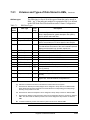
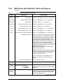
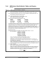
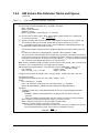
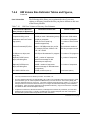
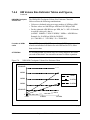
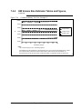
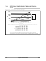
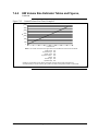
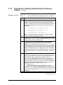
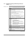
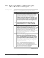
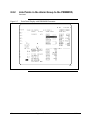
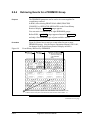
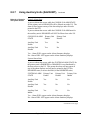
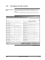
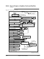
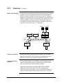
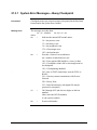
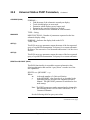
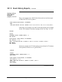
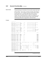
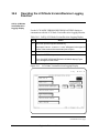
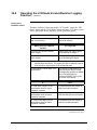
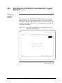
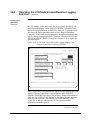
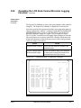
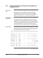
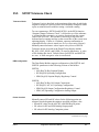
8.8.4
Example
Figure 8-5
Retrieving Events for a PRIMMOD Group,
Continued
In Figure 8-5, events were retrieved for points with DIST841 or
FLAG1 in their PRIMMOD parameter in units 01 and 97.
Example of PRIMMOD Event History
33458
33459
174
Engineer’s Reference Manual
06/04
8.8.5
Alarm Annunciation Using PRIMMOD Groups
Description
Figure 8-6
Figure 8-6 shows, after the PRIMMOD point configuration is done,
you can do the following to make use of the PRIMMOD group:
• assign PRIMMOD group to a button LED,
• assign PRIMMOD group to a box on the Area Annunciator display,
• build a custom schematic display that shows the alarm status of the
PRIMMOD group.
If you build a point specifically to use as a primary module for alarm
grouping, you may want to consider giving the primary module point
the same name as the Schematic assigned to the button.
PRIMMOD Alarm Annunciation
Process Schematic
Alarm Schematic
Annunciator Display
Button
Display the
PRIMMOD
- Alarm Status
- Alarm Count
DIST841
Primary Module Point
FIC100
PRIMMOD=DIST841
FIC200
PRIMMOD=DIST841
TI100
PRIMMOD=DIST841
TI200
PRIMMOD=DIST841
Unit 1
Unit 2
33460
06/04
Engineer’s Reference Manual
175
8.8.6
Using Multiple PRIMMODs for AM Alarms
MPRODs
In R520, the Multiple PRIMMOD (MPROD) alarms option allows a
single alarm on an AM point to be reflected in four alarm groups in
addition to the standard PRIMMOD parameter group to be used for
alarm displays and event history.
Background
The four additional alarm groups are identified by four string-type
parameters, $MPROD1–$MPROD4. All AM alarmable points have
these four $MPROD parameters. The PRIMMOD and $MPROD
groups may be referenced from displays, and button LEDs, and used
for event history retrieval.
Reference
Reference these publications for more information:
Publication
Section
Engineer’s Reference Manual (this document)
Application Module Control Functions
8.8, PRIMMOD Alarm Groups
2.3.15 Process Alarms
Application Module Parameter Reference Dictionary
Application Module Forms
Application Module Form Instructions
System Control Functions
176
4.3 Alarming
Engineer’s Reference Manual
06/04
8.8.7
Using Auxiliary Units ($AUXUNIT)
Auxiliary unit
In R520, all alarmable AM, NIM, HG point types have an Auxiliary
Unit ($AUXUNIT) parameter that allows all process alarms on a
point to be dynamically redirected from the point’s primary unit to an
alternate unit for alarm displays.
Background
On the US, process alarms that have an $AUXUNIT parameter are
directed to the Auxiliary Unit instead of the primary unit for unit
alarm counters and alarm summaries. All other event types received
at the US belong to the primary unit only.
If a point has an $AUXUNIT parameter, then both the primary and
auxiliary units must be configured to the US’s local area database in
order to change a parameter value on that point.
A point’s $AUXUNIT can be changed on a US by a schematic, DEB,
ALTER PARAMS, or detail display. When an $AUXUNIT is
changed, alarms from the prior Auxiliary Unit are cleared and alarms
on the new Auxiliary Unit are displayed. The key level access can
limit who is permitted to change this value.
Process Alarm
Behavior
The alarm enable status of a point’s assigned unit, not the auxiliary
unit, determines the annunciation behavior of the point. Here is an
example:
Assume that point TIC200 is assigned to unit A1 and has an
$AUXUNIT of B2.
•
•
If the Console alarm state for unit A1 is DISABLED, process
alarms for point TIC200 will not be annunciated to this console
regardless of the Console alarm state of unit B2.
If the Console Alarm State for unit A1 is ENABLED, process
alarms for point TIC200 will be annunciated to this console
regardless of the Console Alarm State of unit B2.
Of course, individual alarm priority levels continue to apply.
The following tables show how the Console and System Alarm states
affect the display of Auxiliary Unit alarms on the US Alarm displays.
Continued on next page
06/04
Engineer’s Reference Manual
177
8.8.7
Using Auxiliary Units ($AUXUNIT),
Behavior of Console
and System Alarms
Continued
Console Alarm State
A process alarm that occurs while the CONSOLE ALARM STATE
for the primary unit is DISABLED will be filtered out at the US. The
alarm will not appear on any of the alarm displays and will not be
printed in the RTJ.
A process alarm that occurs while the CONSOLE ALARM state for
the auxiliary unit is DISABLED will NOT be filtered out at the US.
CONSOLE ALARM
STATE
Primary Unit
Enable
Primary Unit
Disable
Auxiliary Unit
Enable
Yes
No
Auxiliary Unit
Disable
Yes
No
Yes – Alarm WILL appear on the Alarm Summary displays
No - Alarm WILL NOT appear on the Alarm Summary displays
System Alarm State
A process alarm that occurs while the SYSTEM ALARM STATE for
the primary unit is INHIBITED or DISABLED is not distributed by
the data owners to the US. This means the alarm will not appear at
any of the alarm displays and will not be printed in the RTJ (for
DISABLED state) or sent to the HM (for the INHIBITED state).
SYSTEM ALARM
STATE
Primary Unit
Enable
Primary Unit
Disable
Primary Unit
Inhibit
Auxiliary Unit
Enable
Yes
No
No
Auxiliary Unit
Disable
Yes
No
No
Auxiliary Unit
Inhibit
Yes
No
No
Yes – Alarm WILL appear on the Alarm Summary displays
No - Alarm WILL NOT appear on the Alarm Summary displays
Continued on next page
178
Engineer’s Reference Manual
06/04
8.8.7
Using Auxiliary Units ($AUXUNIT),
Reference
Continued
Refer to the following publications for more information:
Publication
Section
Application Module Control Functions
Application Module Parameter Reference Dictionary
Application Module Forms
Application Module Form Instructions
Data Hiway Box/Slot, and Data Point Forms
HG Point Forms
Process Manager Configuration Forms
PM Point Forms
Advanced Process Manager Configuration Forms
APM Point Forms
High-Performance Process Manager Configuration
Forms
HPM Point Forms
Hiway Gateway Parameter Reference Dictionary
Process Manager Parameter Reference Dictionary
Network Forms
Network Form Instructions
Process Operations Manual
06/04
Section 7, Alarm and Message
Annunciation
Engineer’s Reference Manual
179
8.8.8
Other R520 Alarm Enhancements
Introduction
Other R520 alarm functions, some of which can be used for batch
alarming, are briefly described in this subsection and references to
more complete information are given.
Button LED control
For R520, Button LED control function allows user written CL
applications to control (on/off/blink) the red and yellow LEDs on the
40 configurable LED buttons.
Reference these publications for more information:
Publication
Section
Engineer’s Reference Manual (this document)
Keyboard Button LED Assignment and Control
Control Language/Application Module Reference
Manual
Configuration Data Collection Guide
Button Configuration Forms
Button Configuration Data Entry
Area Form Instructions
Button PRIMMOD or
MPROD assignment
For R520, Button PRIMMOD or MPROD assignment allows runtime
assignment of a new PRIMMOD name to any of the 40 configurable
LED buttons (allowing button assignments to be changed on the fly).
Reference these publications for more information:
Publication
Section
Engineer’s Reference Manual (this document)
33.0, Keyboard Button LED Assignment and Control
Control Language/Application Module
Reference Manual
Actor’s Manual
Configuration Data Collection Guide
Button Configuration Forms
Button Configuration Data Entry
Area Form Instructions
Continued on next page
180
Engineer’s Reference Manual
06/04
8.8.8
Other R520 Alarm Enhancements,
Detail/Group access
level
Continued
For R520, Detail/Group access level option—parameter modification
and control actions on the detail and group displays can be restricted
by NCF keylevel configuration. Reference these publications for
more information:
Publication
Section
Control Language/Application Module Reference Manual
Network Forms
Network Form Instructions
Area Database change
actor
For R520, Area Database change actor—a new actor that allows Area
Database changes to be done from custom schematics and
configurable buttons (allows operators to move easily from one area
to another).
Reference these publications for more information:
Publication
Section
Area Form Instructions
System Startup Guide–Zip Drive
Picture Editor Data Entry
Network Form Instructions
Picture Editor Reference Manual
Actor’s Manual
Silence horns on
console
WARNING
For R520, the silence horns on console function is an NCF
configurable option that causes the silence button to silence all horns
on the same console (all areas assigned to that console). The horn
silence button on one console will not silence the horn generated for
another console, even if that console is on the same area.
If there was one set of horns on a Universal Station within the console
and that station had the Engineering Main Menu on display, when an
alarm was detected, there would NOT be any audible annunciation.
(The Alarm Summary LED would start to blink so there would be
some visual clue.) Wire all annunciator blocks in a console together
to a single set of horns so that if at least one station is not in
Engineering function, the horns will still go off.
Continued on next page
06/04
Engineer’s Reference Manual
181
8.8.8
Other R520 Alarm Enhancements,
Silence horns on
console,
continued
Continued
Reference these publications for more information:
Publication
Section
Process Operations Manual
“Silencing the Horn”
Section 8
Network Forms
Network Form Instructions
RTJ color alarms
For R520, RTJ color alarms function is an NCF configurable option
that allows all process alarms (SOE, process and sequence alarms)
and return-to-normal events to be printed in color on the Real-Time
Journal. Reference these publications for more information:
Publication
Section
Process Operations Manual
Printer Appendix
Network Forms
Network Form Instructions
System Startup Guide–Zip Drive
Keylevel change
journal suppression
For R520, keylevel change journal suppression function allows the
user to suppress the journaling of keylevel change events by actors.
Configure this option from the Engineering Main Menu by selecting
System Wide Values, then selecting Console Data. Reference the
Actors Manual, Section 3.3, 3.4 for more information:
PRIMMOD Status and
Count actors
For R520, two actors are available for reading the composite alarm
status and alarm count of a specified PRIMMOD or Multiple
PRIMMOD. These are actor equivalents of the $PRIMSTS and
$PRIMCNT collectors. Reference the Actors Manual for more
information:
182
Engineer’s Reference Manual
06/04
8.8.9
R610 Alarm Summary Enhancement
DATE Added to
Process Alarm
Displays in R610
In Release 610 the DATE of occurrence of each alarm has been added
to the already existing TIME field in the process alarm displays – Area
Alarm Summary, Unit Alarm Summary and Alarm Annunciator
Display.
Description
When either process alarm display is called up, the TIME/DATE mode
defaults to TIME and the text in the target is set to TIME. Each alarm
entry displays the time that the corresponding alarm occurred.
By repeatedly selecting the TIME/DATE target, three modes toggle in
the order of TIME, DATE or BOTH DATE & TIME. There is no
timer associated with this target so the selected mode will remain in
force as long as the display is not selected again. When another alarm
display (any other display or PRIOR DISP) is selected, the mode
defaults back to TIME regardless of its last mode state.
To accommodate the new target, the existing target “FREEZE
DISPLAY” is shortened to “FREEZE DISP.” When the display is
frozen the text will read “DISP FROZEN.” The time/date mode may
be changed while the FREEZE display is engaged. Although the
freeze mode remains in effect, the time/date field itself will be
modified accordingly.
The “SORT : PRIORITY” target is also shortened and now reads
“SORT: PRIORTY.”
Reference
See Process Operations Manual for additional information about these
displays.
06/04
Engineer’s Reference Manual
183
184
Engineer’s Reference Manual
06/04
Section 9 – Data Entity Builder Operations
9.0
Reserved
In earlier versions of this manual, this section contained guidelines for Data Entity Builder
Operations. Refer to Data Entity Builder Manual. This section has been retained to direct
users familiar with an earlier version of this manual to the new location of the information and
to preserve the validity of references to other sections of this manual.
06/04
Engineer’s Reference Manual
185
186
Engineer’s Reference Manual
06/04
Section 10 – Native Window System Performance Displays
(Toolkit)
10.0
Overview
Purpose of the Native
Window system
performance displays
These Native-Window displays are provided to facilitate your access
to TPS system performance and loading data that you can use for the
following purposes:
• To allow you to evaluate your present system performance and
system loading to find opportunities to improve its performance or
to add system load by adding additional functions or activities.
• To monitor system performance and system loading so that you
become aware of deteriorating performance or increased system
load before either causes a problem.
• To diagnose the cause of poor performance or high system loading
so that you can make adjustments to correct the problem.
Some of the information on these displays may not be meaningful
except to the most technically competent and experienced users. Such
information is provided because it can be very useful to Honeywell
technical people when you call them for assistance.
The “Toolkit”
Honeywell TPS system maintenance and service personnel often refer
to these displays as the Toolkit displays. Although the term is not used
in this document, it is considered synonymous with Native Window
System Performance displays.
CAUTION
CAUTION—Honeywell makes no claim to the accuracy or usefulness
of these displays. They are intended to assist a trained technician in
diagnosing system problems.
Any value changes made from these displays are subject to the normal
key switch and access lock restrictions.
06/04
Engineer’s Reference Manual
187
10.1
Preface
Where these displays
find performance
information
In all but a few cases, the information on the Native-Window system
performance displays is read from the Processor Status Data Points
(PSDPs) in one or more nodes on the LCN. Every node has a PSDP
and each node shares a common set of PSDP parameters. Each node
type (AM, NIM, US, etc.) also has a unique set of PSDP parameters
for its type.
For more information on PSDPs, refer to Section 22 in this manual.
How the displays are
delivered
These displays are contained in volume or directory TLK1 on the
Honeywell-provided media. The following are the media that contain
TLK1:
Zip Disk &Z1 - TLK1 is a directory on this Zip disk.
The content of TLK1 can be automatically loaded when you install the
system software. See 10.2 in this manual for the directory’s size
requirements.
Refer to 13.3 in this manual for detailed instructions for installing any
volume or directory.
What you must do to
install and use the
displays
The following are the major steps for installing and using the System
Performance displays:
Table 10-1
188
Procedures for Installing and Using the Displays
Step
Action
Reference
1
Install the displays in a volume or directory that the
Pathname Catalog points to.
10.2
2
Call up the System Performance Display Menu,
PERFMENU.
10.3
3
Select targets on the menu to call up the other
displays.
10.4
4
Review the description of the content of the
displays.
10.4
5
Follow the guidelines for using and interpreting the
information on the displays.
10.5
6
Follow the instructions for using the clock display to
check cables.
10.6
Engineer’s Reference Manual
06/04
10.2
How to Install the System Performance Displays
TLK1 files are
installed automatically
in R500
For R500 and beyond, the TLK1 volume or directory is automatically
loaded in an HM when you load the system software. For the R400
version, the TLK1 volume or directory is not automatically loaded in
an HM when you load the system software; you must find space for
its content and manually load it.
Memory space
In R400 and later, the approximate memory space occupied by TLK1
files is 180 KB.
Making performance
displays available to
your Universal
Stations
If you have enough space in any volume or directory that a Pathname
Catalog points to, you can copy the contents of TLK1 into such a
volume or directory. This makes the system performance displays
accessible in any US that is running with the area database that
contains that Pathname Catalog.
Providing for updates
TLK1 displays are updated with major maintenance releases.
For this reason, we suggest you make TLK1 a net directory and have
each area’s pathname catalog point to TLK1.
Detailed installation
procedure
06/04
For the detailed procedure for installing a volume or directory that,
like TLK1, is not automatically loaded in an HM when you load the
system, refer to 13.3 in this manual.
Engineer’s Reference Manual
189
10.2.1 Table of Current TLK1 Versions
DISPLAY
PERFMENU
NODEPERF
DATACHNG
QUIKTRND
CPUCHKR
HEAPCHKR
HEAPMIN
PARCHKR
AMDETAIL
AMTREND
SLTCONFG
HEAPFRAG
CHKPTIME
CLOKMODE
CLOKSYNC
CLOKTRAN
CLOKCABL
UCNCOMM
UCNEVENT
NIMTREND
NGDETAIL
NGTREND
HMDETAIL
HMTREND
HGTREND
UCNSUMM
NODESTA1
NODESTA2
CNAMEREV
DRVSTS
CBREV
R400
R400
NON
E
R232
R400
R400
R400
R400
R400
R400
R400
R232
R400
R300
R400
R400
R400
R320
R321
R321
R322
R400
R400
R400
R400
R430
R430
R411
R431
R431
R411
R500
R500
R500
R520
R520
R500
R600
R600
R500
R620
R620
R500
R640
R640
R500
R650
R650
R500
R651
R651
R500
R411
R411
R410
R411
R411
R400
R410
R420
R420
R411
R411
DELETED
DELETED
DELETED
DELETED
R411
R411
R322
R410
R410
R410
R410
R322
R411
R411
R411
R411
R420
R410
R411
R411
R410
R411
R411
R400
R410
R420
R431
R411
R411
R411
R411
R410
R411
R411
R400
R410
R500
R431
R411
R411
R411
R411
R410
R411
R411
R400
R410
R500
T431
R411
R411
R411
R411
R410
R411
R411
R400
R410
R500
R431
R411
R411
R411
R411
R410
R411
R411
R400
R410
R500
R431
R411
R411
R411
R411
R410
R411
R411
R400
R410
R500
R431
R411
R411
R411
R411
R410
R411
R411
R400
R410
R500
R431
R411
R411
R411
R411
R410
R411
R411
R400
R410
R500
R431
R411
R411
R411
R411
R322
R410
R410
R410
R410
R322
R411
R411
R411
R411
R420
R410
R500
R500
R500
R500
R500
R500
R500
R500
R411
R411
R411
R411
R420
R410
R500
R500
R500
R500
R500
R500
R500
R500
R411
R411
R411
R411
R510
R410
R500
R500
R500
R510
R500
R500
R500
R500
R411
R411
R411
R411
R510
R410
R500
R500
R500
R510
R500
R500
R500
R500
R411
R411
R411
R411
R510
R410
R500
R500
R500
R510
R500
R500
R500
R500
R411
R411
R411
R411
R510
R410
R500
R500
R500
R510
R500
R500
R500
R500
R411
R411
R411
R411
R510
R410
R500
R500
R500
R510
R500
R500
R500
R500
R411
R411
R411
R411
R510
R410
Continued on next page
190
Engineer’s Reference Manual
06/04
10.2.1 Table of Current TLK1 Versions,
DISPLAY
R400
IOPMDATA
RULASTAT
HWYPERF
SISF
UCNVERSN
PLCGCOMM
CALCULTR
CLOKSTAT
AXMPERF
HISGRPS
AMDIAGNS
ARCFGALM
EPLCGCOM
LCNVIEWR
LVRLOG
HOLDBRTH
Continued
R430
R431
R500
R520
R600
R620
R640
R650
R651
R322
R411
R323
R420
R420
R430
R420
R430
R322
R411
R323
R420
R420
R430
R431
R431
R431
R322
R411
R323
R420
R420
R430
R431
R431
R500
R430
R322
R411
R323
R420
R420
R510
R431
R431
R500
R430
R510
R510
R510
R520
R322
R411
R323
R420
R420
R510
R431
R431
R500
R531
R510
R510
R510
R520
R430
R530
R322
R411
R323
R420
R420
R510
R431
R431
R500
R531
R510
R510
R510
R520
R430
R530
R322
R411
R323
R420
R420
R510
R431
R431
R500
R531
R510
R510
R510
R520
R430
R530
R322
R411
R323
R420
R420
R510
R431
R431
R500
R531
R510
R510
R510
R520
R430
R322
R411
R323
R420
R420
R510
R431
R431
R500
R531
R510
R510
R510
R520
R430
R530
R530
R620
R620
CDET_CLR
R620
R620
AMCLDBUG
R650
R650
AMCLDSPL
R650
R650
CHANINFO
ATTENTION
06/04
R651
.
ATTENTION—Local database corruption fixes from R411 were
backed into R410 before volume distribution. Uninitialized values
cause an error on the first call up of a display using TLK1 DDB
values after node load. Errors will not reoccur after the first display
use.
Engineer’s Reference Manual
191
10.3
How to Call Up the System Performance Displays
To call up the System
Performance Displays
Menu
If you have configured a button to call up the PERFMENU display,
on a station with any operator display on the screen, press that button.
The menu appears.
If you do not have a button to call up the menu, call up any operator
display and follow these steps:
Table 10-2
Procedure to Call Up a Performance Display
Step
Action
Result
1
Press the [SCHEM] key.
A port appears in the upperleft region on the display.
2
In the port, enter PERFMENU and
press the [ENTER] key.
The System Performance
Displays Menu appears.
3
On the menu, select any target.
The selected display
appears.
To see the targets on menu page
SELECT
two, select FOR PAGE 2 .
192
Engineer’s Reference Manual
06/04
10.4
The Displays and Their Content
Performance Displays
Menu
Below are pages 1 and 2 of the Performance Displays Menu. To see
any of the remaining displays, just select one of the targets on this
display.
To see the second page (below), touch the SELECT FOR PAGE 2 target.
Continued on next page
06/04
Engineer’s Reference Manual
193
10.4
The Displays and Their Content,
Continued
Continued on next page
194
Engineer’s Reference Manual
06/04
10.4
The Displays and Their Content,
Continued
Display descriptions
A brief description of the function of each display is beside each
target and is generally self-explanatory. The explanations that follow
describe the use of some displays for functions that may not be
readily apparent. (For function LCN Node Version Revision
Logging, R520, see Engineer’s Reference Manual—this manual).
Current Display
Parameter
In R600 a new read only parameter, CURRDSP, is implemented to
enable the user to determine what display is on the Universal Station
screen. The parameter allows the user to:
• Track which displays are most used.
• Determine which displays are no longer used.
• Determine the sequence of displays invoked by the operator.
• Find the name of the schematic that is currently on display.
• Put the schematic source filename on each schematic.
The contents of this PSDP can be queried by the same method as any
current PSDP. This includes using a custom schematic, AM CL, etc.
Checker Target
Some displays have a Checker Target that allow you to set a test
value for the parameter being displayed. For example, CPUCHKR
uses a default value of 25 and compares all node CPUFREE values
against that value. Any value less than or equal to the check value is
reverse highlighted. Another example is the PARCHKR display with
a default check value of 100. All values larger than or equal to the
value are reverse highlighted. It depends on the specific parameter
whether the test is "up" or "down" significant. The Checker Target
allows setting a specific value for test and easy use since in some
cases sorting out numbers is inconvenient.
Parameter Access and
Value Change display
The DATACHNG display can be used to read up to 10 parameter
values at once. You can also change one or more parameter values.
You do this by selecting one of the parameter/value lines on this
display. Then enter the entity name and parameter in the left port and
the new value in the right port and press [ENTER]. Enter the entity
name (tag name or reserved entity name) and parameter in the
NAME.PARAM form.
You don’t have to have an Engineer’s Keyboard to use this display;
when it first appears, “$”, “(”, and “)” appear in the name/parameter
port. You can use them or strike over them, as necessary.
Value changes from this display are subject to the normal key switch
and access lock rules.
Continued on next page
06/04
Engineer’s Reference Manual
195
10.4
The Displays and Their Content,
Node-related displays
Continued
The following displays contain information from a user-specified
node or from all nodes on the LCN:
Table 10-3
Node-Related Displays
Display
Description
NODEPERF
Node performance display. Displays the values for key
performance parameters in the PSDP for the node you
select. Six of the values are shown as bar charts, as well as
digital values.
PARCHKR
Displays the average parameter access rate per second
from PSDP parameter PARSEC for each node on the LCN.
Values for nodes not installed or not operating are blank.
AMTREND
HMTREND
NGTREND
Display a trend for each of several key PSDP parameter
values for the node you select.
AMDETAIL
HMDETAIL
NGDETAIL
Display the values for a large number of significant PSDP
parameters for the node you select.
HOLDBRTH
HOLDBRTH for a node increment when a data request is
not provided within 2.5 seconds.
AMCLDBUG Allows user to define the filter options for finding process
changes caused by AM/CL, and for starting and stopping
the collection of AM/CL process changes.
AMCLDSPL
Buffer that contains up to 100 of the last process changes
caused by AM/CL. It lists the point names and the
parameters changed, the values stored, and the names of
the AM points and the AM/CL blocks that are performing the
stores.
CHANINFO
Shows the names of applications that have been allocated
channels in the applicable GUS or APP node.
Continued on next page
196
Engineer’s Reference Manual
06/04
10.4
The Displays and Their Content; Continued
Quick Trend display
for user-selected
values
Table 10-4
Quick Trend Display
Display
Description
QUIKTRND Provides up to four trend traces for parameter values you
enter. Enter the entity name (tag name or reserved entity
name) and parameter in the NAME.PARAM form.
Instructions for the use of this display are built in.
SELECT
To see them, select FOR HELP .
LCN cable diagnostics
The $LNMENU target presents an LCN cable diagnostics menu. Refer
to LCN Guidelines - Implementation, Troubleshooting, and Service
for LCN cable diagnostics instructions.
Processor free-time
display
Table 10-5
Heap displays
Processor Free-Time Display
Display
Description
CPUCHKR
For each node on the LCN, shows the average of the
percentage of time the processor was idle or free over the
last fifteen seconds. For each node, this value is read from
PSDP parameter CPUFREE. Values for nodes not
installed or not operating are blank.
The following displays contain heap memory information from all
nodes on the LCN. Values for nodes not installed or not operating are
blank. Heap memory is memory in a node that is reserved for use by
the node software. The software uses and releases the heap memory
dynamically, reducing the overall amount of memory needed to run
the software.
Continued on next page
06/04
Engineer’s Reference Manual
197
10.4
The Displays and Their Content, Continued
Table 10-6
Heap Displays
Display
Description
HEAPCHKR
Checkpoint Time and
Interval display
Box/slot verification
display
Displays the value in the nodes’ PSDP HEAPFREE
parameter. The HEAPFREE value is the number of heap
words currently not in use.
HEAPMIN
Displays the value in the nodes’ PSDP HEAPMIN
parameter. The HEAPMIN value is the minimum number of
heap words left free since the node was started.
HEAPFRAG
Checks each node’s HEAPFRAG against an entered check
value.
Table 10-7
Checkpoint Time and Interval Display
Display
Description
CHKPTIME
Shows period, offset, duration, and starting time values for
the HM you select. These values are read from the node’s
PSDP TIMEBASE(n) value array. You can change the
checkpoint period and offset from this display, but before
you do, refer to 21.2.2 in this manual and heed the
CAUTION about creating system performance problems.
Table 10-8
Box/Slot Verification Display
Display
Description
SLTCONFG
Allows convenient verification of the box/slot configuration
in the HG against the actual hardware in the box.
Only HLPIU, LLPIU, LEPIU, DHP and the MCs are
supported.
To use, enter the two-digit hiway and box data. Mismatches
in the configuration are marked in red.
Incorrect entries generate an error display and a reset
target.
Continued on next page
198
Engineer’s Reference Manual
06/04
10.4
The Displays and Their Content, Continued
Clock displays
(CLOKSTAT)
The clock status (CLOKSTAT) display contains system clock
information from all nodes on the LCN. Values for nodes not
installed or not operating are blank.
Table 10-9
Clock (CLOKSTAT) Displays
Display
Description
CLOKMODE Displays the clock operating mode for each LCN node:
• MASTER—The node supplying the primary hardware
clock.
• SLAVE—The node supplying the backup hardware clock.
• LISTENER—All other nodes using the LCN broadcast
clock.
• LOCAL—Any node using an internal precision reference.
CLOKCABL
Displays the clock operating mode for each LCN node:
• ALTCABLA or ALTCABLB—Clocks are being received
alternately on both cables. This is proper operation.
• CBLA or CBLB—Clock received only on cable A or cable
B.
• NOUPDATE—No clock received on either cable.
CLOKSYNC
Displays the clock synchronization status for each LCN
node.
• PRECREF—Synchronized to an internal or ac precision
reference.
• SUBSYNCH—Synchronized to a time-frame received
from the subchannel clock system.
• DIGSYNCH—Synchronized to a time-frame received
from the digital clock system.
• NOTSYNC—Clock not synchronized.
CLOKTRAN
Displays the clock translation state for each LCN node.
• TRNSLTR—Identifies which K2LCN/K4LCN-based node
on the network is translating a subchannel clock to a
digital clock.
• NONTRNS—Identifies the other K2LCN/K4LCN nodes
and all other non- K2LCN/K4LCN nodes.
Clock translation is required in a system that mixes nodes
using some K2LCN/K4LCN processor boards and some
other processor boards. In a system using either all or no
K2LCN/K4LCN processor boards, every node’s status is
NONTRNS.
See 10.6 in this manual for information on using the clock displays.
06/04
Engineer’s Reference Manual
199
10.5
How to Interpret the Information on the System
Performance Displays
A general
recommendation
We recommend that you use these displays during normal operation
to view and record key PSDP values when the system is running well
as a “baseline.” Then, from time to time or when there is evidence of
overloading or poor performance, you can compare your baseline
values with the new values to determine what has changed.
If you wait until there is evidence of trouble before you use these
displays, it may be too late to take preventive measures. Even then,
you will likely find these displays helpful, if not essential, for
analyzing poor performance or overloading.
One way you can record the data on these displays is to use the Print
Screen function.
The Processor Status
Data Point
Except for some user-defined parameters, all parameters shown on
the System Performance displays are read from processor status data
points (PSDPs) in the LCN nodes. Every node has a PSDP and each
PSDP has several hundred parameters and parameter values. For
more information about PSDPs, including definitions of all PSDP
parameters accessible by users, refer to Section 22 in this manual.
Continued on next page
200
Engineer’s Reference Manual
06/04
10.5
How to Interpret the Information on the Performance
Displays, Continued
Guidelines for key
parameter values
The following tables list PSDP parameters that are especially useful
in monitoring the performance and loading. All nodes have these
parameters.
Memory-Use Values
The following parameters contain memory-use values:
Table 10-10
Parameter
Processor Load
Indicator
Memory-Use Values
Display
Guidelines
HEAPFREE NODEPERF
This value typically exceeds 10,000 words.
However, experience has shown that AMs
can have HEAPFREE values in the range of
20,000 to 30,000 words and still operate
properly.
HEAPMIN
NODEPERF
Except for AMs, this value should be 75,000
words or more.
HEAPFRAG NODEPERF
This heap fragmentation value is normally 0
or 1. Values of 3 or 4 are rare, and can
indicate impending node failure.
HEAPFRA2
This heap fragmentation value is normally 0
or 1. Values of 3 or 4 are rare, and can
indicate impending node failure.
NODEPERF
CPUFREE indicates the load on the node’s processor:
Table 10-11 Processor Load Indicators
Parameter
CPUFREE
Display
CPUCHKR
Guidelines
Except for short intervals (a few seconds),
this value should not go below 15%. Nodes
that use the 68020 microprocessor have
significantly less processor-free time than
those that use the 68040 microprocessor. In
Release 500, CPUFREE calculations are
based on clock time, not instruction loop
times. Do not compare R500 values with
previous release values.
Continued on next page
06/04
Engineer’s Reference Manual
201
10.5
How to Interpret the Information on the Performance
Displays, Continued
Parameter-Access
Load Values
The following parameters contain parameter-access load values:
Table 10-12
Parameter
PARSEC
Memory-Use Values
Display
PARCHKR
Guidelines
This is the average number of parameters-persecond requested from this node by other
nodes. Normally it should not exceed the
following values:
• 68020 HG—630 parm./sec. + 90 points/sec.
AM load (1200 parm./sec. with no AM load)
• 68040 HG—960 parm./sec. + 120
points/sec. AM load (1800 parm./sec. with
no AM load)
• 68020 NIM—750 parm./sec. + 90
points/sec. AM load (1200 parm./sec. with
no AM load)
• 68040 NIM—1400 parm./sec. + 120
points/sec.(2000 parm./sec. with no AM
load)
• 68020 AM—90 parm./sec. + 410 points/sec.
support for other nodes
• 68040 AM—120parm./sec. + 615points/sec.
• CG—100 parm./sec. + 500 points/sec. due
to array access
RPARSEC
NODEPERF
Indicates this node’s parameter-per-second
read access rate on other nodes.
SPARSEC
NODEPERF
Indicates this node’s parameter-per-second
store access rate on other nodes.
RPARSEC and SPARSEC can help you to determine which nodes are
causing a PARSEC load on this node.
ATTENTION
This note is to clarify the values that should not be exceeded, in the
“Guidelines” column of PARSEC in the Memory-Use Values table,
above. For example, for “68020 HG—630 parm./sec. + 90 points per
second AM load” the 90 points per second AM load, based on the
cluster model, implies an AM read/store access on the HG of
approximately 2 reads to 1 write per point.
Continued on next page
202
Engineer’s Reference Manual
06/04
10.5
CAUTION
How to Interpret the Information on the Performance
Displays, Continued
.
Parameter-access
load values, figure
CAUTION— Parameters-per-second counts can be misleading
because certain parameter requests count as one, but cause a heavy
load on the data owner. Examples of parameter requests that create a
heavy load are.
• accesses into value arrays
• requests by Group displays and
• requests by Detail displays
The following conceptual figure shows the relationship of the
parameter-access load values: PARSEC, RPARSEC, SPARSEC,
REQUESTS, and RREQUESTS.
Figure 10-1
Parameter-access load values relationships
LCN
RREQUEST
REQUESTS
PARSEC
RPARSEC
NODE
Read
Store
"Y"
SPARSEC
Responder
(server)
Read
Requestor
(client)
Store
15045
Continued on next page
06/04
Engineer’s Reference Manual
203
10.5
How to Interpret the Information on the Performance
Displays, Continued
Trend displays
Below are some guidelines for interpreting the data on the trend
displays provided in volume or directory TLK1. These apply to all
the trend displays except QUIKTRND.
• When the display first appears, select SELECT & SPECIFY xx and
enter the node number for a node of the type served by the display.
• Start the trend by selecting
START
TREND
. In a few seconds, the trend
traces should begin to appear at the right edge of the trend.
• The default trend scale (rate) is 24 hours. To change it, select
CHANGE
RATE
and enter a new rate code. Available rate codes are on
the second line on the display.
• Each of the trended parameter values is presented in digital form
below the trend. The color of the parameter name and value
indicates the color of the corresponding trace. The X axis range is
also indicated by a number of the same color.
• To learn the meaning of the parameter values, refer to Section 22.
Using QUIKTRND
204
To use QUIKTRND, see its built-in help displays.
Engineer’s Reference Manual
06/04
10.6
Use the Clock Display to Find Crossed LCN Cables
Introduction
For an LCN segment where the clock signals from the clock master
and slave nodes are provided by CS/R boards, you can use the
CLOKCABL display to verify that the segment does not have crossed
LCN cables.
Here, we discuss a procedure you can use to check for crossed LCN
cables.
LCN cable checks that
can’t be made
This method of checking for crossed LCN cables:
• Can only be used on segments that use CS/R boards.
• It cannot detect crossed fiber-optic cables.
The LCNI tests in HVTS (Hardware Verification Test System) can be
used to check crossed cables not covered by this method. Refer to
Hardware Verification Test System for this information.
Normal clock
operation
On systems using normally operating clocks, the CLOKCABL display
should show each node using either ALTCBLA or ALTCBLB.
• The clock alternates between the A and B cables every 50
milliseconds.
• All nodes probably won’t report using the same cable at the same
instant.
Crossed cables can
cause system failures
Operating with crossed LCN cables (coaxial or fiber optic) can cause
a system failure if a cable malfunctions.
WARNING
WARNING—If you find crossed LCN cables when you make the
check described below, you cannot safely reconnect the crossed
cables while the system is controlling the process. This is because
you will have to remove both the A and the B cables at the same time.
If the system is controlling the process, defer reconnecting the crossed
cables until the system can be taken off control, but do not defer for a
long time.
False indications
When the clock subsystem is damaged, the CLOKCABL display cannot
dependably show which cable is receiving clock signals.
If the following checking procedure does not give predictable results, your
clock system may require maintenance.
Continued on next page
06/04
Engineer’s Reference Manual
205
10.6
Use the Clock Display to Find Crossed LCN Cables,
Continued
Clock checking
procedure
This procedure checks for crossed cables. Remember, it can’t find
crossed fiber-optic cables and is only for LCN segments that use
CS/R boards.
Table 10-13
Step
1
Checking Procedure for Crossed LCN Cables
Action
Call up the CLOKCABL display.
Result: Every active node displays either ALTCBLA or ALTCBLB. All
nodes don’t have to show the same cable, but all must indicate
“ALT” (alternating). This means an A and a B cable are connected to
each node and all nodes are receiving the alternating clock
messages.
Note: You may still have crossed cables, but the electronics are OK.
If this step fails, check for bad cables or faulty electronics.
2
Determine the two clock source nodes software has assigned:
• Use the CLOKMODE display to determine MASTER and SLAVE.
• If it doesn’t show them, use SYSTEM WIDE VALUES and
CLOCK SOURCE targets from the ENGINEERING MAIN
MENU.
Each of these nodes must have a CS/R board in its I/O slot. One
supplies the cable A clock and the other supplies the cable B clock.
3
Remember any nodes containing K2LCN processors:
• Use the CLOKTRAN display to note a node marked TRNSLTR.
• Use the CLOKSYNC display to note nodes marked DIGSYNCH.
Ignore these nodes containing K2LCNs in steps 4 through 7.
4
Physically locate a master or slave node. Remove the coaxial Tconnector from its CS/R board (leave the LCN cables connected).
Result: If there are no crossed cables, the CLOKCABL display
shows either all CBLA or all CBLB at all active nodes on the system.
5
If the result of step 4 is not true, you probably have a crossed cable.
Trace the cables and analyze the physical cable system. Example, if
all but one node shows CBLA, the cables may be crossed between
that node (CBLB) and the node that precedes it on the way from a
CS/R board.
6
Uncross cables at the suspected node (remember the WARNING
on the previous page).
Result: If the display shows either all CBLA or all CBLB at all active
nodes, the problem is solved. Reconnect the T-connector you
removed in step 4 and continue to step 7.
Continued on next page
206
Engineer’s Reference Manual
06/04
10.6
Use the Clock Display to Find Crossed LCN Cables,
Continued
Clock Checking
Procedure, continued
Table 10-13
continued
Step
7
Checking Procedure for Crossed LCN Cables,
Action
Check the CLOKCABL display again after a few moments. Note: It
might take up to five minutes for a system to show all nodes
operating properly, although the reaction is usually much quicker.
Result: ALTCBLA or ALTCBLB at all nodes is proper operation.
8
ATTENTION
06/04
.
Shut down, wait for QUALIF, and Manual Load the HM with the
Operator (Online) Personality from the &Z1 and BACKUP NCF Zip
disks. HM should go to HMON OK. Allow it to run for 5 minutes (to
initialize the history files) then shut it back down, wait for QUALIF,
and load the initialization program from the &Z1 and BACKUP NCF
Zip disks. HM should go to HMOFF OK.
ATTENTION—Another method to find crossed LCN cables is by
using the $LMENU display, part of the LCN Cable Diagnostics
displays, which provides a count of single cable transmissions
received by each LCN node. If an LCN cable is crossed, the display
shows a smaller number for any node that does not receive the single
cable transmission. All nodes must have R420 (or later) software
loaded and the master LCN node must have a Revision D firmware
K2LCN board. For more information, refer to the LCN Cable
Statistics section of the LCN Guidelines - Implementation,
Troubleshooting, and Service manual.
Engineer’s Reference Manual
207
10.7
Use the Channel Information Display to Monitor
TPS/TPN Channel Activity
Channel Information
Display description
(R651)
With R651, Information for each TPS channel in a GUS node or in an
APP node is collected in PSDPs and then shown on the Channel
Information Display (CHANINFO) below. The PSDPs contain
information such as the task associated with each channel, and
whether the channel is configured as a high-priority data access
channel. Refer to section 22 for the list of GUS and APP node
PSDPs, and the PSDP definitions.
There are a maximum of 30 configurable channels that are shown on
the display. The channels are allocated during node start-up.
However, there are applications that request a channel when the
application is started. In this case, a channel is allocated to the
application if there is an available channel.
208
Engineer’s Reference Manual
06/04
10.7
Use the Channel Information Display to Monitor
TPS/TPN Channel Activity, Continued
Displaying channel
information for a node
Perform the procedure in Table 10-14 to view channel information for
a particular GUS or APP node.
Table 10-14 Displaying Channel Information for a Node
Step
1
Action
Select the Select for Node target on the CHANINFO display.
Result: An entry port appears.
2
Enter the node number of the GUS or APP node.
3
Press ENTER key.
Result: CHANINFO display for the requested node appears.
4
Definitions of
CHANINFO display
items
06/04
For more information about the items shown on the CHANINFO display,
press the HELP key to view the help display.
Definitions of the terms that can appear in the CHANINFO display
are contained in Table 10-15. The table also lists the applicable
external load module for each software application that is allocated a
TPS/TPN channel.
Engineer’s Reference Manual
209
10.7
Use the Channel Information Display to Monitor
TPS/TPN Channel Activity, Continued
Table 10-15 CHANINFO Display Definitions
*
External
Load
Module
Application Description
MS_SERVER_1
MSCHEM
GUS actors and parameter access
MS_SERVER_2
MSCHEM
GUS alarm collectors
MS_SERVER_3
MSCHEM
GUS trend support
MS_SERVER_4
MSCHEM
GUS PMK Support (raise/lower keys)
X$OKBAS
MSCHEM
GUS operator keyboard support
YH_ALARM_SRV
GUSALG
GUS alarm summary
YH_SERVER_1
YGOCX
Faceplate data collection
YH_SERVER_2
YGOCX
Faceplate data store
$$CDS_SERVER
AMCL06
Custom Data Segments
RESERVED
N/A
Channels are reserved for internal use and
are not available to any application
Application
Name
*
The applications listed are standard applications. When optional applications
are used, the name of the optional application is displayed instead of the
standard application.
210
Engineer’s Reference Manual
06/04
Section 11 – Schematic Files
11.0
Overview
Introduction
The Picture Editor is used to build the custom schematics (graphic
displays) that describe the customer's process.
The Picture Editor allows you to interactively create a graphic
representation of portions of the process for the operator to use. The
schematic is written to a source file, using subpictures as desired.
Figure 11-1 illustrates the picture editor-file relationships.
References
06/04
Refer to Picture Editor Data Entry.
Engineer’s Reference Manual
211
11.1
Picture Editor Tips
Introduction
The following tips may be useful for building schematics with the
Picture Editor.
Text versus Graphic
Alpha (Text) versus Graphic—Each character is a distinct object and
its text (alpha) has two levels: Foreground and Background. The
priority scheme (where G is graphic, F is foreground text, and B is
background text) is as follows:
• GFB—Graphic object obliterates the portion of the alpha object
under it.
• FBG—Alpha object obliterates the portion of the graphic object
under it at a character-resolution level (that is, a space "blanks" a
character position of the graphic, 8x16 pixels in size).
• FGB—Alpha object obliterates only the portion of the graphic
object under the character lines of the alpha object (that is, graphic
shows between and within open areas of characters). This can also
provide more flexible color priorities.
Line optimization
If a line with text on top is desired, draw one line and set priority FBG
so text shows on top.
You can draw lines with up to 50 segments. You can more efficiently
draw complex images with lines and segments by retracing segments
instead of drawing multiple lines.
For example, you could more
efficiently build, store, and
invoke this apparent 5-line
image by drawing it as
fourteen segments, retracing as
indicated by the dashed curves,
than you could by drawing the
image as five individual, onesegment lines.
11
1
8
14
4
3
12
2
13
6
9
10
15
7
5
2972
Continued on next page
212
Engineer’s Reference Manual
06/04
11.1
Picture Editor Tips,
Relationships
Figure 11-1
Continued
The figure below shows the relationships between Picture Editor files.
Picture Editor File Relationships
SCHEMATIC
SOURCE
SCHEMATIC
OBJECT
.DS FILE
.DO FILE
EDIT
AREA
DATABASE
.DA FILE
COMPILE
US
with
ENGINEERING
PERSONALITY
SCHEMATICS LOADED
INTO US WITH ON—
PROCESS PERSONALITY
AT NODE STARTUP
USING AREA DATABASE
PATHNAME
CATALOG
US
with
OPERATOR
PERSONALITY
Note:
The US Operator Personality is loaded as shown below. The room remaining for
schematics depends on the size of the various components and the number of
schematics depends on the size of the schematics load.
1.
2.
3.
4.
5.
6.
PERSONALITY IMAGE
NCF DATA
AREA DATABASE
STANDARD DISPLAY ABSTRACTS
BUTTON CONFIGURATION
SCHEMATICS (in order of pathname catalog)
1232
Continued on next page
06/04
Engineer’s Reference Manual
213
11.1
Picture Editor Tips,
Color Priority
Continued
Remember that colors of graphic objects have a priority similar to that
for alpha and graphic. The priority (and color "number") for the
highest to lowest (highest covers or overwrites lower) color are the
following:
Table 11-1
Color Priority
WHITE
CYAN
7
6
MAGENTA
BLUE
5
4
YELLOW
GREEN
3
2
RED
1
Also remember that subpictures are added to the schematic using the
current color. This affects the priority of the subpicture.
Text Optimization
As the number of text objects increases, the size of the source and
object files and the invocation time increase. The following
characteristics of text objects should be understood to help keep text
objects at a minimum.
• Characters added to a picture in separate ADD TEXT commands
are held as separate text objects.
• Characters added on different lines of the picture are held as
separate text objects.
• Horizontally contiguous characters are added as one text object if no
behavior change occurs.
• A space created by the SPACE BAR is a legitimate character and
takes room in the source and object files (see illustration below).
WATER CHILLER #1
=
WATER CHILLER #1
Space
1
One Text Object
16781
214
Engineer’s Reference Manual
06/04
11.1
Picture Editor Tips,
Continued
Text Optimization,
continued
• A space created by the CURSOR controls is not a legitimate
character. It acts as a delimiter for determining a new object (see
illustration below).
WATER CHILLER #2
=
WATER CHILLER #2
Right Cursor
1
2
3
Three Text Objects
16786
NOTE: In this instance, the cursor does not save space because it
causes the creation of another text object in the Picture Editor.
Subpictures
Performance of the display is always decreased by using subpictures.
The primary purpose is to simplify schematic building by establishing
a library of frequently used subpictures on the schematic volume or
directory on an HM, if available, or on a special, library Zip disk. A
complex subpicture must be used three times before the overall size
of the source files for schematics is reduced. A simple subpicture
may have to be used 20 times before the overall size of the source is
reduced; however, subpictures always reduce the size of the object
file.
Continued on next page
06/04
Engineer’s Reference Manual
215
11.1
Picture Editor Tips,
Common
Abbreviations
Continued
The following common abbreviations are used in the Picture Editor.
Table 11-2
Common Abbreviations
Commands
ADD
DELETE
LINE
MODIFY
MOVE
NEW
READ
SCALE
SELECT
SET PATH
SOLID
SUBPICTURE
TEXT
TRANSLATE
WRITE
Colors
A
DEL or D
L
MOD or M
MOV
N
R
SC
SEL
SP
S
SUB
T
TR
W
BLACK
BLUE
CYAN
GREEN
MAGENTA
RED
WHITE
YELLOW
BLK
BLU
CY or C
GR or G
MAG or M
R
WH or W
YEL or Y
Intensity
FULL
HALF
FUL or F
H
Changing behavior
When changing behavior, first select the behavior to be changed, then
add the new behavior.
Editing keys
The primary keys on the engineering keyboard for editing are:
CANCEL—Used to recover from the last command entered. Cancels
and restores the schematic as it existed before last command.
ERASE—Used to erase last coordinates entered. The command is
terminated if all coordinates for the command are erased.
Use separate
removable media for
files and subpictures
Using separate Zip disk directories for Files and Subpictures—When
building a schematic that uses many subpictures from a Zip disk
library, build the schematic on the library medium, then copy it to the
display medium when complete. This prevents transferring large
numbers of subpicture files to the build Zip disk.
Building Displays
Enter text first, then subpictures, lines, etc. There is less flexibility
with text than with subpictures and lines. Enter lines in text mode as
much as possible. This allows for faster build time and even lines and
spaces.
Continued on next page
216
Engineer’s Reference Manual
06/04
11.1
Picture Editor Tips,
Continued
Entities are bound to
schematic when
compiled
Remember that the entities are bound into the schematic as they are
compiled. The entities referenced in the schematic must be built and
loaded, and the owning node must be operating on the LCN when the
schematic is compiled.
Deleting entity from
node does not delete
entity
Remember that deleting an entity from the owning node does not
automatically delete the entity from references in schematics, CL
programs, groups, etc. If an entity is being removed from the system,
the schematics, CL programs, groups, logs, etc., must be rebuilt and
recompiled with the entity reference removed.
Use layout forms
The schematic layout forms (SW88-551 to -559) help to make the
build process more efficient.
Schematic loading
order
Remember that the schematics are loaded into a US at startup, based
on the order listed in the pathname catalog, and the number of
schematics loaded depends on the space available after loading the
other data in the US, and the size of the schematics being loaded from
the catalog.
CAUTION
06/04
.
CAUTION—"Semireserved" Entity Names—Several entity names
are reserved for use by the Picture Editor and the Button
Configurator. In many cases, if you happen to use one of these names
for a data point name (tag name), there will be no conflict. If you do
use one of these names as a tag name, that data point can't be accessed
by the Picture Editor nor the Button Configurator. Therefore, if you
are, or will be, using the Picture Editor or the Button Configurator,
you must refer to Appendix C of the Picture Editor Reference
Manual, to see the list of "semi-reserved" names, and to make sure
that you don't use any of them as a tag name.
Engineer’s Reference Manual
217
218
Engineer’s Reference Manual
06/04
Section 12 – Control Language Files [Task 28]
12.0
Overview
Introduction
This section provides tips and precautions for the use and handling of
the data and files used in compiling, linking, and loading CL
programs.
Keep the following principles in mind during CL operations.
CAUTION
06/04
CAUTION—These items are extremely important because, if, for
some reason, you are unable to use data from the HM to restart a
node, you will need the backup &ASY medium to restart that node.
The latest .SE , .SP files must be available to reload USs and CGs,
and if they are not, you may have to go through a major rebuild of
your CL functions. The .GD files must be available to rebuild and
reload data points.
• Remember to copy your .SE and .SP files to any new &ASY
medium provided with a software update.
– The custom names you have built are saved only if you replace
the empty .SE and .SP files on the Honeywell-supplied &ASY
with the .SE and .SP files from your operating &ASY.
– Execute-Command files ASY_BKUP.EC and CLNCFBKUP.EC
are provided on the Honeywell &ASY Zip disk to help maintain
these files (see your latest Customer Release Guide).
Immediately after copying these files, use the Utilities' Protect
command to protect them from being accidentally overwritten or
deleted (of course, you will need to unprotect them the next time
you make such a backup copy).
• Also remember to make a backup copy of your custom GDF (.GD)
files on a Zip disk, so that if those files become unavailable from
the HM you still have GDFs to use in rebuilding or reloading points
with CDSs.
These backup files should also be protected.
Engineer’s Reference Manual
219
12.1
File Handling Tips
File name consistency
Remember that a US or CG cannot start up unless the &ASY
directory used by that node contains the version of the name files
that is consistent with the other USs and CGs in operation on the
LCN.
Make backup copy
Be sure to make a backup copy when you update your parameter-list
(.PL) files on your CL Parameter List volume or directory (through
the Compiler's -UL option).
Use of two floppies
When using two Zip disk drives for CL operations, the first Zip disk
drive has the Zip disk with the source that contains the object, listing,
GDFs, and parameter list and the second Zip disk drive has the
&ASY Zip disk.
Entity not
automatically deleted
from CL reference
Remember that deleting an entity from the owning node does not
automatically delete the entity from CL references.
Deleting points
Once a number of CL slots is established on an AM point, that
number can't be reduced except by using the DEB to delete the point,
then rebuilding the point. If the point is deleted and rebuilt, and CL is
to be used with it again, CLSLOTS must be set to at least the number
of blocks to be linked to the point, and the CL structures must then be
relinked to the point.
Continued on next page
220
Engineer’s Reference Manual
06/04
12.1
File Handling Tips,
File relationships
Figure 12-1
Continued
The figure below shows the relationships between CL files.
CL File Relationships
Custom
GDFs,
.GD
CL Source
File
.CL
CL Object
(AM or MC)
.AO or .MO
Source
Definition
Custom
Enumeration
Names
Parameter
List
.PL
Compile
US with
Engineering
Personality
Link
Enm-Sets.SE
(name1).SE
(name2).SE
CL Listing
.LS or .LE
(Normal or Error)
LCN Node
Custom
Parameter List
Names
Par_List.SE
Custom
Segment/
Parameter
Names
SEGMENTS.SP
PARAMTER.SP
Note: There is a separate suffix for AM and MC object and listing files for normal
listings or listings with errors.
The custom name files and standard parameter lists exist on the &ASY volume.
06/04
Engineer’s Reference Manual
221
222
Engineer’s Reference Manual
06/04
Section 13 – Area Database, Content, and Use
13.0
Overview
Introduction
06/04
This section describes the content of the area database and how the
area for a console is established. It also points out that changes to the
area database actually take place in a US only when the database is
loaded into that US. The relationship of the Engineering functions’
Unit Assignment display to the Operator's functions’ alarm summary
and annunciator displays is defined.
Engineer’s Reference Manual
223
13.1
Database Composition
Description
The area database is a collection of standard display definitions,
custom graphic displays (schematics), unit assignments, reports, and
logs that are used by an operator to control his area of plant
responsibility. The area database is loaded into each US and normally
each US in a console is loaded with the same area database. Each
area database contains information on the following:
Units Assignable to Area
Annunciator Display
Overview Display for Area
Real-Time Journaling
Configuration for Area
Group Displays for Area
Area and Unit Trend Displays for Area
Report and Log Definitions for
Area
Module Summary Definition
Button Configuration for Area
Custom Displays Pathname Catalog
for Area
Display Set Definitions for Area
Hiway/Node Annunciation Policy
The area database contains pathnames for files that define custom
schematics, free-format logs (FFLs) and button configuration (see
Section 2 on file system operation). Any number of areas can refer to
the same files.
Plan ahead
Plan ahead! Have the pathnames established, particularly those for
button configuration, schematics, and free format logs, before
building the area database.
Where database
entries are used
Displays for any area can contain data from anywhere (any unit or
node) in the system. Also any number of areas can access the same
data.
Limits of unit
assignment
Unit assignment for an area only designates which units and data
points the operator can interact with and which alarms are reported to
that operator.
When changes
become effective
Changes can be made to an area at any time; however, the changes do
not become effective until a US is reloaded with the new area. Note
that if any US is on a newly changed area, all USs on the same
area must be reloaded to ensure consistent operation.
Continued on next page
224
Engineer’s Reference Manual
06/04
13.1
Database Composition,
Making changes
06/04
Continued
Once all USs in a console are loaded and running, changes can be
made to the area database and to schematics and button configuration
without reloading the USs with their personalities. Here is a
summary of the major steps involved.
• Use the Data Entity Builder to make changes to the area database.
• Use the Picture Editor and the Button Configurator to make changes
to schematics and button configuration. Compile the resulting
source files and store the object files in &Dan (where an is area
number) or in a user volume in the HM. Be sure that the Pathname
Catalog in the area database points to this volume.
• Use the Console Status display on one US to change the area
database in all USs that are to operate with the new or revised area.
Then, if needed, also change it in the first US. The system
resynchronizes messages, alarms, and system status across the area.
Engineer’s Reference Manual
225
13.2
Assigning Units to an Area
Description
Area database configuration includes the assignment of up to 36
process units to an area. The order in which the units are assigned
can be used to determine the position of the unit-annunciator picks
(targets) on the Area Alarm Summary Display, the Unit Alarm
Summary Display, and the Alarm Annunciator Display.
Database assignment
In Area Database Configuration, the Unit Assignment Display has 36
picks—one for each possible unit. These picks have a one-for-one
relationship to the unit-annunciator picks on the alarm summary
displays and on the Alarm Annunciator Display, as shown on Figure
13-1. Unit picks that are not selected on the Unit Assignment Display
remove the corresponding unit-annunciator pick from the alarm
displays. Thus, you can leave space between the unit-annunciator
picks and make them easier to use.
Figure 13-1
Unit Assignment Picks and Unit Annunciator Picks
Engineering Personality
AREA DATA BASE
Unit Assignment Display
01
02
17
18
19
20
35
35
If not selected,
Process Operator Personality
Area Alarm Summary, Unit Alarm
Summary, or Alarm Annunciator Display
01
02
17
18
19
20
35
36
this unit annunciator
won't appear.
226
Engineer’s Reference Manual
50883
06/04
13.3
Adding a New Volume or Directory to the Pathname
Catalog
Introduction
Honeywell provides several displays that are used to investigate the
system operation and performance of your TotalPlant Solution (TPS)
system equipment.
In a few cases, the information on these displays may not be
meaningful to customer personnel, but this information can be
invaluable to Honeywell personnel who help to analyze difficult
situations. If you contact our Technical Assistance Center (TAC) or
the technical service facility in your region for help in diagnosing
LCN problems, they may ask you for information from one or more
of these displays.
Displays available
Table 13-1 is a list of the directory names containing the displays
(files) currently available, their contents, and the top menus used to
access them.
• For instructions for performing LCN Cable Diagnosis, refer to LCN
Guidelines - Implementation, Troubleshooting, and Service.
• For instructions for performing System Performance Checks, refer
to Section 10 in this document.
Table 13-1
Name
Displays Available
Contents
Top Menu
DIA1
LCN Cable Diagnostic Displays
$LNMENU
TLK1
System Performance Displays
PERFMENU
Continued on next page
06/04
Engineer’s Reference Manual
227
13.3
Adding a New Volume or Directory to the Pathname
Catalog, Continued
Methods of accessing
a volume or directory
There are two methods by which your system can call up these
displays in a volume or directory:
Table 13-2
Methods of Accessing a Volume or Directory
Method
1
2
Copy directories on a
Honeywell Zip disk to
your HM
Requirements
By calling files in
volumes or directories
on an HM (already
listed in your
pathname catalog).
• You must have room in an existing
directory on the HM.
By calling files in
volumes or directories
on a Zip disk.
• Use this method if you don’t have enough
room on an HM.
• You can check currently assigned
pathnames in the SCHEMATIC TITLES
display in the Operator Personality’s
ORGANIZATIONAL SUMMARY from the
SYSTEM MENU.
• This method adds a pathname to the
pathname catalog directory pointing to the
Zip disk.
If you choose to install these files on an HM, first use the following
procedure. If you choose to use Zip disks (removable media), skip this
procedure.
Table 13-3
Step
Procedure for Copying Files to an HM
Action
1
Place the Honeywell-supplied Zip disk in an appropriate drive.
You must be in Universal Personality.
2
Select COMMAND PROCESSOR from the Engineering Main
Menu.
3
Type in the Utilities Copy command (CP) in a similar manner to
the example shown below, then press [ENTER].
In this example, directory DIA1 is being copied from Drive 1 to
the NET directory on the HM.
CP $F1>DIA1>*.DO NET>DIA1>= -D
Result: The directory is copied from the Zip disk to the HM.
Continued on next page
228
Engineer’s Reference Manual
06/04
13.3
Adding a New Volume or Directory to the Pathname
Catalog, Continued
Directory
recommendation
We recommend adding directories TLK1 and DIA1 to a user volume
and copying the files that correspond to each directory from the Zip
disk to the NET. During upgrades, Command EC files write to these
directories.
Adding a pathname to
either an HM or to a
Zip disk
Follow these steps to add the directory’s pathname to the area’s
pathname catalog. Use a US in the Universal Personality.
Table 13-4
Adding a Pathname to an HM or to a Zip disk
Step
Action
1
Select BUILDER COMMANDS from the Engineering Main Menu.
2
Select SELECT AREA from the Command Display.
3
Select the pick for the area served by the US, then press [ENTER].
Result: The Data Entity Builder now knows the area database you
want to change.
4
Select RECONSTITUTE from the Command Display.
Result: New ports appear.
5
In the ENTITY NAME port, type $0ABSTRT and press [ENTER].
Result: After a few seconds, the reconstituted Parameter Entry
display for your pathname catalog appears.
6
In a spare SCHEMATIC PATHNAME port, type the pathname for
your directory on either the HM or Zip disk and press [ENTER].
Examples:
7
$F1>DIA1
or
NET>DIA1
Hold the [CTL] key and press the [F12] key to LOAD.
Result: This loads the pathname catalog into the workfile.
8
Press the [COMND] on the keyboard.
Result: The Command Display appears.
9
Select INSTALL AREA and press [ENTER].
Result: This installs the modified area database in directory &Dnn
(where “nn” represents the area number) and gets rid of the area
workfile (.WF)..
Continued on next page
06/04
Engineer’s Reference Manual
229
13.3
Adding a New Volume or Directory to the Pathname
Catalog, Continued
Doing an area change
on each US
You may want these displays to always appear on a certain Universal
Station or on several Universal Stations in several areas. If you want
more than one station to access these displays, repeat this procedure
for each Universal Station.
Follow these steps to do an area change. Use a US that is running the
Operator functions. If you’re using a Zip disk, the disk containing the
volume or directory in step 6 above must be mounted.
Table 13-5
Area change
schematic
Making an Area Change
Step
Action
1
Select the Universal Station whose database you want to change.
2
Select AREA CHG from the Console Status Display.
3
Select the target for the area whose database you just modified,
then follow the prompters to complete the area change.
4
To check your work, press the [SCHEM] key, type in the display
name, and press [ENTER]. Example: type $LNMENU [ENTER].
Upon completion of an Area change in R520 and later systems, the
US that changed areas will attempt to call up a custom built
schematic. The schematic must be stored by the file name
AREACHnn (nn = area changed to by US).
The schematic’s object file (AREACHnn.DO) must reside in the
same directory as the Area Data Base file AREAnn.DA. If the
schematic is found, prior display information is deleted. This means
that pressing the Prior Display key is ineffective after an area change
(until some other display has been called). If an AREACHnn
schematic is not found, the Console Status is called up.
230
Engineer’s Reference Manual
06/04
Section 14 – Data Binding in the TPS System
14.0
Overview
Introduction
This section introduces the concept of data binding and describes the
consequences of that binding. The effect of data binding on
configuration and reconfiguration of the system are also discussed.
Continued on next page
06/04
Engineer’s Reference Manual
231
14.0
Overview,
Continued
What is Data Binding?
The conversion of external references, such as entity and parameter
names, files, and such, into the internal IDs, actual file use, and data
is called binding. This process occurs at different times for different
types of data in the NCF, NVCF, entities, schematics, CL, area
database, and so on. First let's discuss the configuration-time binding.
When does it occur?
A summary of data-binding times for the TPS system is given in the
following table. A detailed matrix of binding relationships is given
for each of the discussion areas in the tables in this section.
Table 14-1
Summary of Data Binding in the TPS System
Type of Data
Effects of changes
Binding Time
When Effective
NETWORK CONFIGURATION
NCF Installed
First Node Load
NETWORK VOLUME
CONFIGURATION
NCF Installed
HM Initialize
UNIT/AREA/CONSOLE NAMES
NCF Installed
Node Load
AREA UNIT ASSIGNMENT
Area Install
Area Database Load
INTERENTITY REFERENCE
Entity Load
Entity Load
GROUPS/LOGS/TRENDS
Area Install
Area Database Load
SCHEMATICS
Compile
Area DB Load/Invoke
BUTTON CONFIGURATION
Compile
Area Database Load
CL DIRECT REFERENCE
Compile & Link
Link to Entity &
Activate
CL INDIRECT REFERENCE
Link
Link to Entity &
Activate
AREA PATHNAME LIBRARY
Invoked
Area Database Load
The figure below provides a quick cross-reference of the effects of
changes in each of the engineering activities. The matrix is set up to
indicate that, if a change is made in the data listed on the left, the data
listed at the top is affected and must be rebuilt or modified.
Continued on next page
232
Engineer’s Reference Manual
06/04
14.0
Overview,
Continued
Effects of changes,
continued
Figure 14-1
Quick Reference Matrix of the Effects of Data Changes
Effect of Changes:
Type of Data Change
Node Data
Schematics
Groups, Trends
Logs, Reports
CL Programs
NYCF
Area Data
NCF
X = Up to severe impact if certain nodes not reloaded
I = HM must be initialized
U = US(s) must be reloaded
O = Affects only owning node, or file change
Unit Names
X
I
Area Names
X
Console Names
X
System Wide Values
X
System or User Volumes
X
Entity Data
U
O
O
O
O
O
Delete Entity References
U
O
O
O
O
O
Groups, Trends, Logs, Reports
U
O
O
Area Pathname Catalog
U
Schematics
U
Button Configuration
U
I
CL Programs
O
O
Node data is the owning node's database.
1235
Sequence and
relationship of data
changes
Figure 14-2 is a "bubble chart" that indicates the sequence and
relationship of data changes. The special "on-line reconfigure"
bubbles indicate that changes to that data affect the NCF and require
certain nodes on the LCN to be reset and then reloaded with the new
NCF in the data that is loaded. For the "on-line reconfigure" bubbles,
the nodes that must be reloaded and the order in which they must be
reloaded is indicated by the "on-line" Network Configuration
displays. Refer to Network Form Instructions and Network Data
Entry for more details. Where an “on-line reconfigure” bubble leads
to a regular bubble (i.e. “Build/Add/Delete AMs” leads to “Build/
Reconstitute Entities and Store in .EBs or IDFs”), the appropriate
nodes must be reloaded BEFORE performing the second type of data
change (“Build/Reconstitute Entities and Store in .EBs or IDFs”).
Continued on next page
06/04
Engineer’s Reference Manual
233
14.0
Overview,
Figure 14-2
Continued
Configuration Sequences and Data Relationships
On-Line
Build/Edit
System Wide
Values
Reconfigure
On-Line
On-Line
On-Line
Build/Edit
Console
Names
Reconfigure
Build/Add/
Unit Names
Build/Add/
Delete HMs
Reconfigure
Reconfigure
On-Line
On-Line
On-Line
On-Line
On-Line
Build/Add/
Delete HGs
Build/Add/
Delete AMs
Build/Add/
Delete CM60s
Build/Edit
HM Volumes
Build/Edit
Area Names
Reconfigure
Reconfigure
Reconfigure
Reconfigure
Reconfigure
On-Line
Build/
Reconstitute
Entities and
Store in IDFS
Build/Add/
Delete USs
Reconfigure
GDF
Revisions
by Honeywell
Copy HM
Content to
Floppies
Load Entities
in Owning
Node
Delete
Entity
Compile and
Link CL/AM,
Compile and
Load CL/MC
Build/Edit
Free Format
Logs
Build/Edit
Area
Database
Initialize
HM
Build/Edit
Schematics
and Buttons
Reload
HM
Reload
USs
234
Engineer’s Reference Manual
06/04
14.1
Binding of Unit, Area, and Console Names
Description
An example
At configuration time, the unit, area, and console name lists that were
created are used in various engineering activities. The position of a name
in a list is retained for later use, and if you reconfigure the names by
rearranging them, not just adding on the end of the list, the external name
that appears, when used by the system, will be different from what you
intended. The system maintains the list position as originally configured,
which affects external name conversions as well as many file-system
volume and directory names that use the unit and area number (internal
list position, not external name) as part of the volume or directory name.
It isn't just the NCF that refers to these names, data points also do. To
change the position in the lists you have to rebuild all the data points.
For example, in this sketch, the first unit configured is AC. The system
knows this unit by its index number 1. "AC" and "Air Conditioner" are
external names. Most of the system knows the unit as "the unit with index
1," not by the external names. Once you get this configuration loaded in
the NCF.CF file and the nodes begin to use it, the unit IDs and names can
get hopelessly confused if you make subsequent changes except by adding
units at the next-higher indexes.
3697
Entries for Unit
IDs
06/04
Unit-Names configuration includes configuring unit IDs. The unit ID
consists of two characters. If only numbers are used, you can enter a
single digit in either position or you can enter two digits, but you can't
enter a single digit and two digits that amount to the same number. For
example, you can enter "1" and "02," but you can't enter "1" and "01."
You can enter "03" and "4," but you can't enter "03" and "3."
Engineer’s Reference Manual
235
14.1
Plan ahead
236
Binding of Unit, Area, and Console Names,
continued
Rearranging the area, unit, and console name lists has widespread effects
that must be understood. Basically, do it correctly the first time and only
add to the lists thereafter. Table 14-8 in paragraph 14.8 details the area
database binding. Unit names have wide-spread effects because they are
embedded in IDFs and other structures. Area names affect only the USs
in which the affected area database is loaded.
Engineer’s Reference Manual
06/04
14.2
Binding of NCF Data
Description
The details of data binding in the NCF are shown in Table 14-2.
Changes can be made to the working NCF, but they do not become
"known" until the working NCF is installed by the configurator. At
the time the NCF is installed, you must be aware that the new NCF
will not be usable until all nodes that are affected by the change have
been shut down and reloaded with data that includes the new NCF.
The time stamp is changed every time the NCF is installed (F2
operation is performed on the NCF), whether or not any data
changes occurred.
Table 14-2
Detailed Matrix of NCF Data Binding Relationships
BINDING TIME
TYPE OF DATA
CONFIG
INSTALL
LOAD AREA
LOAD
NOTES
Unit Names
xx
xx
Position in list at area load time.
Area Names
xx
xx
Position in list at area load time.
Console Names
xx
xx
Position in list at area load time.
US Node Configuration
xx
Node configuration only, no data.
HG Node Configuration
xx
Node configuration only, no data.
AM Node Configuration
xx
Node configuration only, no data.
HM Node Configuration
xx
Node configuration only, no data.
CG Node Configuration
xx
Node configuration only, no data.
System Wide Values
xx
System values for paper size,
jogs, % increments, shift definition,
batch, etc.
HM Volume
Configuration
xx
NVCF is used to setup the HM
configuration during HM
initialization. If volume
configuration is changed, the
affected HMs must be initialized.
06/04
Engineer’s Reference Manual
237
14.3
Binding of HM Local NVCF Data
Description
Table 14-3
Table 14-3 gives the detailed data-binding relationships for the
NVCF. The NVCF is created (as file Lnp_NVCF.MM) in the HM's
local volume when the HM is initialized (F6 Initialize function in
Volume Configuration). If an HM is reloaded or autoboots for any
reason, and the NVCF in the local volume and the NVCF data in the
NCF on the &ASY directory being used do not match, the HM comes
up in its initialization personality, not in its normal operational
personality. Remember that before initializing the HM, you must first
save critical files (to another HM or to a removable medium) or the
data in the files on the HM being initialized will be lost.
Detailed Matrix of NVCF Data Binding Relationships
BINDING TIME
TYPE OF DATA
HM INIT
NOTES
Volume Selections
xx
NVCF changed at install time, but
data not effective until HM initialized
Volume Sizes/Allocation
xx
User Volume Assignment
xx
History Assignment
xx
Checkpoint Assignment
xx
Journal Assignment
xx
Archiving Assignment
xx
CL/D Storage Assignment
xx
238
CONFIG INSTALL
Engineer’s Reference Manual
06/04
14.4
Binding of Entity Data in the Data Entity Builder
Description
Table 14-4
The binding of entity-build data by the DEB occurs at several
different times, depending upon the type of data and the operation
being performed. The following discussion explains the binding time
for entities, parameters, and values. Table 14-4 gives detailed databinding relationships for the data handled by the DEB.
Detailed Matrix of DEB Data Binding Relationships
BINDING TIME
TYPE OF DATA
BUILD
Entity Name
LOAD
RECONSTRUCT
xx
Parameter Name
xx
ASCII Data
xx
Custom State Names
xx(1)
NOTES
Name used in IDF and error files as
external form.
xx(2)
xx
1. For entity references.
2. If GDFs are revised.
Not automatically updated when
changes to custom name
parameter occur.
Value Range Checks
xx(1)
xx(2)
xx(3)
1. Not for HG parameters.
2. For entity references.
3. If GDFs are revised.
Default Values
xx(1)
xx(2)
xx(3)
1. Initially at build.
2. PED reset to defaults after F12
load command.
3. If GDFs are revised.
Continued on next page
06/04
Engineer’s Reference Manual
239
14.4
Binding of Entity Data in the Data Entity Builder,
Continued
When names and
values are bound
Parameter names and enumeration values are bound at the time
ENTER is pressed. This means parameter names and enumeration
values are held in internal form in the IDF.
Steps that occur when
an entity is loaded
As an entity is loaded, two steps occur: first the entity ID is
established in the node and then the parameter data is loaded to the
entity. If the data owner fails the load because of bad data, or any
other condition, the entity has still been established and future load
operations must use the overwrite option.
Owning node must be
running when entity is
built and loaded
Entity IDs (tag names) are bound at load time. This means reference
entities (entity names referred to by the entity being loaded) must be
built and loaded, and the owning node must be running on the LCN.
Prevent load-time
errors by loading
entities that reference
each other from the
same IDF
Entities that reference each other (for example, A110 references A200
and A200 references A110) must be loaded from the same IDF, using
the multiple-load command, to prevent load-time errors. This
command establishes all entities before loading so that such crossreferences are correctly satisfied. If the entities do reside in different
IDFs, load the entities, check the error files after all IDFs have been
loaded, and then reload the entities that had a reference error.
If the cross-referenced entity does not exist in the same IDF than it
must have been previous loaded thereby prevented load time errors
from occurring.
External names can’t
change after load time
240
Parameters that allow you to set the external name of a state or value
(self-defining enumerations), are bound at load time. The DEB
prevents modification of the external names once the entity has been
loaded. The entity must be deleted and rebuilt if you want to change
the external names.
Engineer’s Reference Manual
06/04
14.5
Binding of Schematic Data
Description
Schematics cannot be used until they are compiled into object files
used by the area database. The compilation of the schematic cannot
be done until all entities referred to in the schematic are built and
loaded in the owning nodes, and the owning nodes are running on the
LCN. The compilation requires obtaining the internal IDs of the
entities and their parameters that are held in the owning node.
This means that there is no way to see the final schematic, as it will
appear in the Operator's Personality, until called from an Operator's
Personality. Table 14-5 provides detailed data-binding relationships
for schematic variable data, either values or conditions used for
behavior control.
Remember that deleted entities require that schematics that used them
be rebuilt, recompiled, and replaced in the volume or directory
pointed to by the Pathname Catalog.
Table 14-5
Detailed Matrix of NCF Schematic Data Binding Relationships
BINDING TIME
TYPE OF DATA
Subpictures
BUILD/
EDIT
COMPILE
xx
Parameter Name
xx
Custom State names
Schematic Object File
INVOKE
xx(1)
xx(2)
NOTES
xx
Entity Name
ASCII Data
AREA
LOAD
xx
xx
1. If configured to reside in
memory database.
2. If on removable medium
or HM file.
06/04
Engineer’s Reference Manual
241
14.6
Binding of Data in CL Programs
Description
At CL program COMPILE time, direct references (use of
EXTERNAL statement on a block or point name in block header)
require the entities to be built and loaded, and the owning node to be
running on the network. Indirect references are resolved at link time.
As a CL program is linked, direct- and indirect-entity references
require the entities to be built and loaded, and the owning node to be
running on the network.
Table 14-6
Detailed Matrix of NCF CL Data Binding Relationships
BINDING TIME
TYPE OF DATA
Entity Name (Direct)
EDIT
COMPILE
xx
Entity Name (Indirect)
NOTES
Rechecked at Link time.
xx
Parameter Name
xx
Custom State Names
xx
Custom GDFs
xx
ASCII Data
xx
Default Data
xx
242
LINK
Rechecked at Link time.
Engineer’s Reference Manual
06/04
14.7
Binding of Entities and Schematics into the Area
Database
Description
Table 14-7
In order for the area to be configured, the unit and area names must be
defined. Additionally, all references to process or system-entity
names and parameters require the owning node to be loaded with the
data and operating on the LCN. This means that configuration of
groups, trends, and logs cannot be completed until the entities used in
them are built and loaded. Schematics are referred to by only
pathname at configuration time, so schematic object files do not need
to exist during configuration.
The second binding step occurs when the US is loaded (with the
appropriate NCF) and the assigned area database is loaded. At that
time, the pathnames for schematics are used to access the compiled
object files and the files must exist. Note that the schematic object
files can exist only if the entities referred to are built and loaded
before the compile step in the Picture Editor.
Detailed Matrix of Area Data Binding Relationships
BINDING TIME
TYPE OF DATA
EDIT
AREA
INSTALL
Entity Name (Direct)
xx
Parameter Name
Groups
xx
Overviews
xx
Process Module Group
xx
Trends
xx
Logs
xx
Journals and Reports
xx
Alarm Annunciation
Policy
xx
Unit/Area/Console
Names
Custom State Names
06/04
INVOKE
LOAD
NOTES
xx(1)
1. When invoked, if not in memory.
xx
xx
Schematic Object
Help/Associated/
Related Display
AREA
xx
xx
Area database
Engineer’s Reference Manual
243
244
Engineer’s Reference Manual
06/04
Section 15 – Actors and Process Control
15.0
Overview
Introduction
15.1
This section advises that actors are not to be used for actions that are
involved in process control.
Use of Actors
What actors do
In Universal Stations, actors are used to assign actions to targets
(picks) on schematic (custom/graphic) display and to the configurable
buttons on the Operator's Keyboard. An actor is executed one time,
each time its target is selected, or each time its configurable button is
pressed.
Actors can call up a specific display, create text-input ports (TIPS) for
data entry by an operator, read the data entered, and store the data in a
display or in the system database. Actors are very useful for defining
relationships between schematic displays and for making it easy for
operators to use and move between displays.
Actors can be very useful to operators for setting up conditions in the
control system; for example, for setting up initial control conditions
for a sequential operation, starting a sequence or initiating an
abnormal-condition handler. While an actor can initiate control
actions, it does not have the feedback mechanisms nor continuous
monitoring capability that is required for process control; therefore,
actors are not suitable for implementation of control strategies.
Control strategies must reside in AMs, CMs, NIMs, CGs, PMs, LMs,
and process-connected boxes.
06/04
Engineer’s Reference Manual
245
246
Engineer’s Reference Manual
06/04
Section 16 – AM Configuration Guidelines
16.0
Reserved
In earlier versions of this manual, this section contained AM Configuration Guidelines.
Refer to Application Module Implementation Guidelines for that information. This section has
been retained to direct users familiar with an earlier version of this manual to the new location
of the information and to preserve the validity of references to other sections of this manual.
06/04
Engineer’s Reference Manual
247
248
Engineer’s Reference Manual
06/04
Section 17 – Data To Be Used During Configuration
17.0 Overview
Introduction
06/04
This section relates the types of configuration data to the publications
that define each type of data and to the configuration forms used to
record each type of data.
Engineer’s Reference Manual
249
17.1
Publications Defining Configuration Data
References
For information about the overall configuration-data collection
process, refer to the Configuration Data Collection Guide. Also,
refer to the System Startup Guide for the System Startup Task Record.
Before configuring the
system
The following forms should be completed and referenced data should
be available before starting to configure the system. Doing this paper
work first will help to prepare you for efficient configuration of your
system.
This list does not include the various hiway-related publications.
Refer to the Application binder in the Basic System bookset.
Data to be Configured
Publication
Form Used
Unit Configuration
Network Form Instructions
Network Forms
Area Names Configuration
Network Form Instructions
Network Forms
Console Configuration
Network Form Instructions
Network Forms
LCN Nodes
Network Form Instructions
Network Forms
System Wide Values
Network Form Instructions
Network Forms
Volume Configuration
Network Form Instructions
Network Forms
Hiway Configuration
Network Form Instructions
Network Forms
Box/Slot Configuration
HG Parameter Reference Dictionary
HG Data Point Forms
Hiway Gateway Points
HG Parameter Reference Dictionary
HG Data Point Forms
Process Manager Points
PM Parameter Reference Dictionary
PM Configuration Forms
Advanced Process Manager Points
APM Parameter Reference
Dictionary
APM Configuration
Forms
Logic Manager Points
LM Parameter Reference Dictionary
Logic Manager Forms
PLC Gateway Points
PLCG Parameter Reference
Dictionary
PLCG Forms
Application Module Points
AM Parameter Reference Dictionary
AM Data Point Forms
Computing Module Points
CM Parameter Reference Dictionary
CM Data Point Forms
Picture Editor
Picture Editor Form Instructions
Picture Editor Forms
Button Configuration
Button Configuration Form
Instructions
Button Configuration
Forms
Area Database Configuration
Area Form Instructions
Area Forms
HM History Groups Configuration
HM History Group Form Instructions
HM History Group Forms
250
Engineer’s Reference Manual
06/04
Section 18 – Avoiding Mistakes and Errors
18.0
Overview
Introduction
18.1
Notes in this section may help you avoid mistakes and errors.
Guidelines and Warnings
Introduction
This section contains a collection of the significant guidelines,
precautions, and warnings that appear in this and other publications.
If you review this section from time to time, and implement its
content, you should experience a minimal amount of rework and error
correction.
Make a backup set
Start by making a complete backup set of all removable media (Zip
disks) supplied by Honeywell.
Write protect
Remember to write protect the removable media used to store your
configuration.
Continued on next page
06/04
Engineer’s Reference Manual
251
18.1
Guidelines and Warnings,
Follow the DEBloading and
checkpointing rules
Continued
Remember to follow the DEB-loading and system-checkpointing
rules to keep the database consistent:
Table 18-1
Rules
1
Database Loading and Checkpointing Rules
Description
The order in which entities are loaded to a node is significant.
For all references to properly work, always load from the most
current checkpoint medium, or if using the DEB, always use the
same files in the same order to ensure that the sequence of point
loading is consistent and the internal entity IDs remain the same.
For more information, refer to the Data Entity Builder Manual.
2
Always make changes to the existing database.
Do not delete an entity and reload it to make a simple change.
Be sure to reload the last, correct, checkpoint data to reloaded
nodes before doing any operation that loads or links to entities in
the nodes.
3
The "directory" of external entity names is distributed among the
owning nodes; there is no central directory.
Thus, all nodes must be running in the normal on-process
personality to ensure that points are not duplicated.
4
Remember that deleting a point and reloading it changes its
internal ID and that all references have been broken by the delete.
Follow a sequence
Follow the sequence of the tasks in the system-loading and startup
guide. This provides for the most efficient startup scenario.
Make a backup of the
old NCF before
making a new one
Always make a backup copy on a removable medium of the old NCF
(directory &ASY) before installing a new one. This allows recovery
of the system without restarting nodes, if the changed NCF causes
problems in loading nodes or the HM autoboots because of a power
interruption.
If you do not have a removable copy of the NCF in use on the LCN
and the HM NCF has been changed from what other operating nodes
are using, then certain nodes must be reset and loaded from the HM,
including the new copy of NCF in the data that is loaded. See the online Network Configuration displays and also refer to Network Data
Entry.
Continued on next page
252
Engineer’s Reference Manual
06/04
18.1
Guidelines and Warnings,
Precautions when
moving the system
volume (&ASY)
Continued
Moving the system volume from one HM to another requires special
considerations. This is because the system volume contains the
network configuration file NCF.CF and uses the network pathform
for access.
Before making configuration changes, load both HMs with the HM
INIT personality and perform the required changes in the order given
below:
Table 18-2 Procedure Used When Moving the System Volume
(&ASY)
Step
Action
1
Install the new HM configuration.
2
Reload both HMs with the HM INIT personality.
3
Initialize the HM that previously held the system volume.
4
Initialize the HM that will contain the system volume.
5
Copy the HM’s personality image files to both HM’s local
volumes.
6
Reboot the HM that previously held the system volume.
7
Reboot the HM that now contains the system volume.
Limitations of the
“NET” command
Remember, "NET" cannot be used to access files in an HM loaded
with its initialization personality.
The physical-node pathname (PN:n>volm>file.sx) is the only
type of pathname you are allowed to use for an HM during
initialization. This includes the initial loading of the system files to
the HM (&ASY, &HMO, and optionally, &HMI).
Check for errors
Always check the Data Entity Builder error files.
The errors listed may indicate that references to other entities were
not satisfied because the entities had not been loaded.
Use of multiple-load
command
If two entities reference each other, the entities must be
simultaneously loaded by using the multiple-load command.
Write the two entities to the same IDF and multiple load them. The
multiple-load command is a 2-pass operation that allows establishing
the entities, then loading the data, so that references are satisfied.
Continued on next page
06/04
Engineer’s Reference Manual
253
18.1
Guidelines and Warnings,
Entities must exist
Continued
Remember that groups, trends, and logs cannot be built unless the
entities used are built and loaded.
The owning node for entities must be running on the LCN to allow
access and external/internal conversions to occur. Group Edit in the
Operator function allows some flexibility in this area.
You can’t overwrite an
entity’s location to
change it
Remember that you cannot change an entity's location, unit, or build
type by loading with overwrite.
You must delete the entity and load it again to change these
characteristics.
Deleting an entity
does not delete
references to it
Remember that deleting an entity does not delete references to that
entity in schematics, logs, groups, etc.
Each reference to the entity must be deleted in the specific function
that used it.
Internal IDs are
different
Remember that if an entity is deleted, changed, or loaded again with
the same name, it is a different entity and references built before the
delete will not connect to the entity when it is loaded again.
The internal ID is unique for each entity loaded, even if it has a name
that previously appeared in the node, only so long as the database is
kept consistent by following the DEB-loading and the checkpointingoperation rules.
CL compiling caution
Always make a copy of the HM files *.SE and *.SP to a current Zip
disk copy of &ASY when CL has compiled new custom parameter
names.
The new parameter names are propagated across the LCN and the
data-access function prevents startup of any node when the &ASY
directory (removable medium or HM) does not contain the same list
of parameter names as is currently in use by the operating nodes.
Also, always make a backup copy of any updates you make to the
custom parameter-list (.PL) files on your Custom Parameter List
volume or directory.
After you make these copies, use the Utilities' Protect command to
prevent overwriting or deletion of these files.
Continued on next page
254
Engineer’s Reference Manual
06/04
18.1
Guidelines and Warnings,
Continued
Know when binding
occurs
Remember when binding occurs for the type of data you are working
with. Refer to Figure 14-1.
Names must be the
same
Remember that the NCF, NVCF for the HM, and parameter name
files (.SE, .SP) for data access must be the same as any operating
nodes on the LCN at the time a node is loaded and started up.
The loaded node will not be allowed to start up on the LCN if there is
a mismatch of critical data in these files.
Copy .SE and .SP files
Remember to copy your .SE and .SP files to any new &ASY Zip disk
volume provided in a software update.
The custom names you have built are saved only if you replace the
empty .SE and .SP files provided on the standard &ASY medium
with the .SE and .SP files from your operating &ASY.
After you make these copies, use the Utilities' Protect command to
prevent overwriting or deletion of these files.
Backup your custom
GDF files
Remember to make a backup copy of your custom GDF (.GD) files
on a Zip disk.
Use the Utilities' Protect command to prevent overwriting or deletion
of these files.
Know how adding and
deleting points affect
files
Remember that adding or deleting points can affect group and
overview display definitions, schematics, and reports.
Group and overview display definitions must be reloaded if points
they contain are added or deleted.
Report definitions must be reloaded if points they refer to are added
or deleted.
Schematics must be recompiled if points they contain are added or
deleted.
06/04
Engineer’s Reference Manual
255
256
Engineer’s Reference Manual
06/04
Section 19 – Glossary of TPS Configuration Terms
19.0
Overview
Introduction
19.1
This is a glossary that summarizes the terms related to the
configuration process. You may also wish to refer to System
Overview, which contains a more extensive glossary.
Configuration Terms
Alias
Alternative name for a given Zip disk or HM volume in Release 200
and earlier releases. It has no meaning in R210 and later releases.
Alias point
An HG data point that uses the same box and slot on a Data Hiway as
another point in the same HG, but has a different tag name—an alias.
Alias points are created by building and loading only the HG-resident
parameters for a point that already exists in the box and slot, and then
loading the point in the HG. This new point in the HG then has access
to the data in the designated box and slot. Alias points usually have
virtually identical data, but different unit assignments. This allows
alarms for such points to be generated for more than one unit.
Autoboot
A History Module that has been through System Startup Tasks 14, 15,
and 16 can reload and restart itself, if its power has been interrupted
or if its power was turned off and then back on. This is referred to as
"an autoboot" or "autobooting."
Bind
The conversion of external entity and parameter names to the internal
entity ID and parameter ID, as used for LCN communications. The
external/internal conversion can be performed by only the owning
node of the external entity. This means the entity to be bound must
be built and loaded, and the owning node must be running on the
LCN, at the binding time.
Continued on next page
06/04
Engineer’s Reference Manual
257
19.1
Configuration Terms,
Continued
Bootload
The loading of a program or data into a node or device directly
without intervention through some other node or device. This term
arises out of the notion that such an operation is like “pulling itself up
by its bootstraps.” In the TotalPlant Solution (TPS) system, loading
a Universal Station by itself and not through the Console Status
display at another US is referred to as “bootloading” the US. Also, a
History Module can bootload itself (also see “Autoboot”).
Build
Entities are built by interacting with the Data Entity Builder's
Parameter Entry Displays (PEDs) or by exception building. The
entities can then be stored into an IDF for future loading to the
owning node. Building does not include loading in the owning node.
Checkpoint
Storing of the process database from a module or gateway in files
from which the data can be reloaded into the module or gateway,
should it be necessary to restart it. Where a gateway serves process
devices, such as the boxes on a Data Hiway, their process data can be
included in the checkpoint files, and reloaded. The term "checkpoint"
refers to a "snapshot" of the data is acquired at some point in time.
Compile
Custom (schematic or graphic) displays, CL programs, free format
logs, and button configurations are compiled from source data (either
stored, edited images, or textual source programs) into final object
"code" that is actually used at runtime, by the appropriate function. In
general, direct references to entities in the system must be bound at
compile time. This means the entity must be built and loaded, and the
owning node must be running on the LCN, at compile time.
Crash
The unexpected failure of a node that is caused by a situation the
software or firmware in that node cannot manage or under which it
cannot continue to operate. For example, as a node is loaded, the
software checks for proper hardware revision levels, and if they are
not proper, loading stops and the node crashes.
Directory
A named subdivision of a volume to which one or more files is
assigned. Each Zip disk is a volume. HMs can have several volumes.
Each volume can have up to 63 directories. System-reserved directory
names begin with "&" or "!".
Continued on next page
258
Engineer’s Reference Manual
06/04
19.1
Configuration Terms,
Continued
Directory
A named subdivision of a volume to which one or more files is
assigned. Each Zip disk is a volume. HMs can have several volumes.
Each volume can have up to 63 directories. System-reserved directory
names begin with "&" or "!".
Entity
Entities are named collections of data that can be accessed across the
LCN. There are two major entity categories: process data points and
reserved entities. Reserved entities are treated differently than process
data points (see the Data Entity Builder Manual).
Error
A misoperation from which the hardware or software can recover.
For example, memory errors that are corrected by the memory’s
EDAC feature, and errors in data transfers that are detected and
recovered by repeating the transfer.
Establish
Entity IDs are established on the LCN at load time. This means the
entity can be referenced by its external name, provided the owning
node is running on the LCN. The owning node performs the external
to internal name conversion to allow access to data within the entity.
An entity can be established but remain "not loaded" because of errors
or failures that prevent access to parameter data within the entity.
Exception Build
Use of a prebuilt entity as a template and building a number of new
entities, based on a text file of source data. Exception-built entities
are always stored in an IDF. The template entity must reside in an
IDF, either the IDF being built if the &M control line is used or
another IDF if the &X control line is used, in the exception-build
source code.
Format
Typical use of this term is for the operation of formatting Zip disks or
HMs. Formatting consists of writing track headers, establishing the
volume name for a Zip disk, and building the bad-sector table for the
HM. Formatting destroys any previous data on the medium.
HM Load
The operation of loading the system software to the HM(s).
Continued on next page
06/04
Engineer’s Reference Manual
259
19.1
Configuration Terms,
Continued
IDF (Intermediate Data
File)
The IDF is a file used by the Data Entity Builder to store the build
information for an entity. It is not the complete entity description, but
contains the data necessary to support loading to the destination node.
Initialize
For an HM, initialize is establishing the volumes that exist on the
HM. The volume directories are cleared, so all data previously
available can no longer be accessed and must be restored. This term is
sometimes used in place of "format" when referring to Zip disks. The
utilities support initializing the removable media (clearing the
directory and renaming the volume) without "formatting" (writing
track headers).
Invoke
This is the action of calling up a specific function or display on the
US. Typically used for describing the action of calling up a schematic
display.
Kilobyte (KB)
Kilobyte—1024 bytes
LCN (Local Control
Network)
The link through which all the nodes communicate. The term is often
used to generically name the link with the nodes attached—the
system.
LDID (Logical Device
Identifier)
This is a "name" by which Zip disk and printer devices can be
accessed on a console through the utilities. The LDID is of the form
$Fn for Zip disks, and $Pn for the printer (n is 1-20).
Link
The operation of binding final components into the system.
Typically, this is used to describe the CL-link operation where a CLobject program is linked to the entity(s) that uses it. Any indirect
entity reference, which was not bound at compile time, must be bound
at link time. This means the entity must be built and loaded, and the
owning node must be running on the LCN, at compile time.
Continued on next page
260
Engineer’s Reference Manual
06/04
19.1
Configuration Terms,
Continued
Load
“Load” is used for several operations in the system:
• Loading a specific node's memory with a personality image from a
removable medium or HM.
• Loading an entity, using the DEB, to its destination node (or file in
the case of the area database).
• Loading an area database from its file to memory when a US is
loaded and started up.
• Loading a checkpointed database from the checkpoint file to the
memory in an HG or AM.
Megabyte (MB)
1024 KB (kilobytes)
Megaword (Mw)
1 Mw = 2 MB
NCF (Network
Configuration File)
The NCF contains the description of the system, so that each node is
aware of the system structure.
Node
The individual components connected to the LCN are called nodes,
and sometimes modules. Generally, nodes are logical and modules
are physical. The node types are
• US —Universal Station
• HG —Hiway Gateway
• AM —Application Module
• HM —History Module
• CM —Computing Module (DPS6 through the CG)
• CG —Computer Gateway
np
Notation used to represent an HM node pair number. In LCN Node
Configuration, a node pair number is assigned to each single HM, and
to each primary/secondary HM node pair.
Continued on next page
06/04
Engineer’s Reference Manual
261
19.1
Configuration Terms,
Continued
On-Line
Reconfiguration
Changes to Network Configuration that are made with the
configurator in the on-line mode. Such changes require that specified
nodes be shutdown and reloaded with data that includes the revised
network configuration file (NCF).
Owning Node
The node on the LCN in which an entity resides. This node contains
the external/internal entity ID-conversion capability, knows whether a
parameter exists on the entity and, ultimately, contains the data for the
entity.
PED (Parameter Entry
Display)
The information on an entity being built by the Data Entity Builder
that is displayed on the US screen. The information consists of
multiple displays, called the PED set, and the status of the data in
each display is available in the PED Set Status Display.
Personality
A specific software image in a node on the LCN. Nodes typically
have multiple personalities but they don't coexist. For example, the
US has the Operator's Personality and the Universal Personality.
Each requires complete memory load to put the personality in
operation. Other nodes have an on-line personality and an off-line
personality.
Reconfigure
See On-Line Reconfiguration
Removable Media
Zip disks. Such a medium can be removed from its drive and replaced
by another medium of the same type.
Reconstitute
The "back-building" operation—reconstituting an entity from its
owning node or area database file to the Data Entity Builder for
display. In a batch or multiple reconstitute operation, the data is
placed directly into an IDF.
Volume
The name by which a Zip disk or a section of an HM is known. Refer
to "directory." System-reserved volume names begin with "!" or "&".
262
Engineer’s Reference Manual
06/04
Section 20 – Node Loading and Node Dumps
20.0
Description
Overview
The first part of this section provides guidelines for recovering from
the failure of a node to properly load with software and data.
Next, this section provides guidelines and instructions for
implementation of fast-load Zip disks for quick recovery from
interrupted operation, such as might be caused by a power failure.
Finally, this section provides guidelines for dumping the memory
content of failed nodes for analysis.
06/04
Engineer’s Reference Manual
263
20.1
Node Loading Failures
Why a node fails or
crashes
As each node on the LCN (including USs) is loaded with software
and data, the system checks for proper hardware and software revision
levels and for adequate memory in the node. If an incorrect revision
level is detected or the node is found to have inadequate memory, the
node fails (“crashes”).
Do not try to concurrently load both HGs in an HG pair, nor both
NIMs in a NIM pair—one of the gateways may fail. First, finish the
loading of one of the gateways as the primary, then load the other
node as the secondary.
Information about the
crash
Information about such “crashes” is available through the Real-Time
Journal, so one of the first nodes to be loaded should be a US with the
Operator Personality functions. Once that US is loaded, the RealTime Journal should be enabled so that any errors detected as other
nodes are loaded will be reported in the journal (on the printer).
Revision or memory
error crash
If a node “crashes” because of a revision or a memory error, the node
goes to the FAIL state and “-190” appears in the LED display on the
module. The following message is also displayed: “SYS: Unable to
Open NCF File.” The journal message (all on one line) is in this
form:
hh:mm:ss
nnnn
$$NODE ADMIN
CRASH
DET- NODE ADMIN
42
OFF- NODE ADMIN
x
y
60001
Where:
• hh:mm:ss is the hour, minute, and second when the “crash”
occurred.
• nnnn is the module type and number, and interpret the meaning of X
and Y by using Table 20-1.
Continued on next page
264
Engineer’s Reference Manual
06/04
20.1
Node Loading Failures,
Continued
Revision or memory
error crash, continued
Table 20-1
Interpreting Cause of Node “Crash”
IF …
THEN …
X=1
A board revision-level mismatch was detected and
Y is the board's slot number.
X=2
A required board type is missing and Y contains an
indication of the type of board.
X=3
Inadequate memory was detected and Y = the
amount of missing memory in KB.
X = 4 and Y = 0
X=5
A software-revision mismatch was detected.
A board firmware-revision-level mismatch was
detected and Y = the board's slot number.
If any of these errors are reported, a hardware technician should check
all boards in the node to determine if any are missing, if any are the
wrong type, or if any have incorrect option selections (by jumper pins).
Other errors
Other types of loading errors can also be reported in the journal.
Most of these are described elsewhere in this manual.
Clearing a
LOAD FAIL message
To determine the cause of the error message and to clear a LOAD
FAIL message, follow one of the procedures below:
Table 20-2
Display)
Clearing a LOAD FAIL (from the System Status
Step
Action
1
Select the “RETURN” target.
2
All error messages will disappear.
Continued on next page
06/04
Engineer’s Reference Manual
265
20.1
Node Loading Failures,
Continued
The following table applies to AM, PM, CG, etc. displays.
Table 20-3
Clearing a LOAD FAIL Message (from the Console,
Process Network Node; or Device Node Status Displays
Step
Action
1
Select the failed node number.
2
AUTOLOAD NET, AUTOLOAD LOCAL, MANUAL LOAD, and
DUMP NODE targets appear.
3
Select one of the LOAD targets.
4
Red/Yellow message with cause of failure appears.
5
Select error message on top of the screen (see Note).
Result: The error message is cleared and you can try to reload the
node.
NOTE:
If after reading the “reason for failure” message, a different screen is
invoked, the error on top of the screen will disappear.
If a different screen is on the US, other than where the LOAD FAIL
was caused, then the error message on top of the screen MUST be
selected to take you to the displays listed above to clear the message.
266
Engineer’s Reference Manual
06/04
20.2
Description
Fast-Load Feature
In the event of a system disruption, such as might be caused by a
power failure, once the required nodes have power reapplied and are
ready to be reloaded, then a “path to the valve” can be quickly
restored through the use of a user-prepared fast-load Zip disk, or from
an HM that is running and has the right volumes and data.
A thorough understanding of the design of your system is invaluable.
If, for instance, the power failure has not brought down all your HMs,
recovering from an HM that can fast-load your system is probably the
quickest method. In the case where all HMs have been off, then come
on simultaneously and “autoboot” (see below), you can still fast-load
quicker using one of the HMs instead of a Zip disk.
Each fast-load Zip disk (or HM) contains the software and data
required to reload one Universal Station; and to reload one NIM or
one HG.
Prior to R650, APP nodes could not be loaded without a system HM.
With R650, the APP node can be loaded with the APP or AM
personality using a fast-load Zip disk mounted in a US/GUS. The
fast-load zip disk can be used if the system HM fails or if the APP
node loses communication with the HM.
GUS nodes can be loaded manually from a fast-load Zip disk
mounted on a different US/GUS (not the local node) without
requiring the system HM to be on-line.
You can prepare more than one fast-load Zip disk to restore other
paths to valves, as allowed under Honeywell software licensing
policy.
References
See the Process Operations Manual for instructions on the use of a
fast-load Zip disk to reload a US and a NIM or HG to reestablish a
path to a valve, in the Fast Load Procedure section. For additional
reloading options available on a System Status display, see the LCN
Node Reloading and Status Information section.
See the TPS System Operations Guide for instructions on loading an
APP node without using the HM.
Continued on next page
06/04
Engineer’s Reference Manual
267
20.2
Fast-Load Feature,
Continued
Necessity of updating
checkpoint files
Effective use of the fast-load procedure requires careful use of the
guidelines presented later in this section, especially the regular
updating of checkpoint files and other data on your fast-load Zip
disks.
AUTOLOAD targets
To facilitate the quick restoration of paths to valves of a single node,
AUTOLOAD LOCAL and AUTOLOAD NET targets (picks) appear on the
Console Status display, the Gateways Status display, and the node
status displays for other nodes.
These targets simplify the single node loading process by
automatically searching Zip disk drives on the US (AUTOLOAD
LOCAL) or HMs (AUTOLOAD NET) for the directories that contain
the files and data to be loaded.
NOTE
To speed the restoration of paths to valves for multiple nodes, loading
requests should be initiated from the System Status display. See the
LCN Node Reloading and Status Information section of the Process
Operations Manual.
History Module
“Autoboot” feature
When power is first applied to all nodes on an LCN, the HMs load
themselves, or “autoboot.”
If the necessary files are available on HMs, you can load the first
Universal Station quickly using the procedure shown in Table 20-3 in
“Fast-Load Scenario” which follows.
These files are stored on HMs in the system (&0np), personality
images (&1np), area database (&3np), and the HG or NIM checkpoint
(&7np, &8np) volumes. If all these files are not provided, the startup
procedure will go as far as it can, then it will ask for you to supply the
missing files from removable media.
268
Engineer’s Reference Manual
06/04
20.2.1 Fast-Load Scenario
Introduction
When power returns, all modules self-test and the HMs autoboot. You
must start a US up quickly so you can load the remainder of the system.
Loading a US from
itself
This procedure allows a Universal Station to be loaded from a
running HM that has the correct volumes (&1np and &3np) required
for fast-load.
Table 20-4
Loading a US from Itself
Step
Action
1
Push back the upper part of the black frame enclosing the
operator’s keyboard and push the [RESET] button.
Result: the screen will clear.
2
After the “>” prompt is displayed on the screen, press [LOAD].
Result: N,1,2,3,4,X? is displayed.
3
Type N and press [ENTER].
Result: OPR,UNP? is displayed.
4
Choose Operator or Universal personality by typing O or U. Then
press [ENTER].
Result: Loading begins. Wait for the System Status Display to
appear. At this time, not everything has been loaded into the US,
however, the standard abstracts have been loaded.
Continue on without waiting for the button configuration, external
load modules, and memory-resident schematics to be loaded.
NOTE: If loading external load modules, and using backplane
packages (XYPLOT, OPBASE, and OPEQLT, for example) you
must have sufficient memory to load them. Reference the
optional package documentation for memory requirements.
5
Press [CONS STATS] to choose the Console Status display (or go
to the System Status display).
6
From the Console Status display, press the LOAD/DUMP target.
7
Press the AUTOLOAD NET target if you want to fast load from
your History Module.
Press the AUTOLOAD LOCAL target if you want to fast load from
a Zip disk.
Node loading
If all the files needed are on an HM or Zip disk, the node loading
procedure is automatic from this point. If all the files are not
available, the procedure will go as far as it can, then it will ask for
you to supply the missing files from removable media. The stages of
the fast-load scenario that follow will aid you in analyzing the process
and determining what files might be needed.
Continued on next page
06/04
Engineer’s Reference Manual
269
20.2.1 Fast-Load Scenario,
Stages of the Zip Disk
Fast-Load scenario
Continued
If you don’t have all the files on an HM from which you can load the
rest of the nodes, or if the HM did not autoboot, you may want to load
from a Zip disk. The following steps can take place at more than one
console, using more than one fast-load Zip disk.
Table 20-5
Stage
1
Stages of the Zip Disk Fast-Load Scenario
Description
The fast-load Zip disk is used to “bootload” one US in a console.
The node status display abstracts are among the first to be brought
into the US memory, and when they are available for a user to
initiate loading of the NIM or HG on the path to the valve, the US
status goes from LOAD (or READY) to OK.
270
2
The status remains OK unless one or more files could not be loaded
into the US, at which time the status normally becomes OK.
3
As soon as the System Status display appears on the US, the user
selects the NIM or HG that is on the path to the valve and uses the
AUTO LOCAL LOAD target to start the loading of that NIM or HG.
4
When the UCN Status display or Hiway Status display is available,
the user restores the database that is in the UCN node that is on
the path to the valve or in the Data Hiway box that is on the path to
the valve.
5
When it is convenient, the HM or HMs that contain system files are
restarted and all other nodes on the LCN are reloaded, using the
network (HMs) as the source of the files and data. To restore full
operation of USs that were started from fast-load Zip disks, but
may be using out-of-date custom names or schematics, they must
be reloaded from the network (HMs).
Engineer’s Reference Manual
06/04
20.2.2 Fast-Load Implementation Considerations and
Guidelines
Introduction
This section presents considerations and guidelines you should be
aware of while conducting Fast-Load operations.
Access to Display
Abstracts
When a US is reloaded or begins an area change, the following
critical, standard, display abstracts and the button-configuration file,
are brought into the US memory first, to hasten access to them:
Table 20-6
Display Abstracts Loaded First
Title
Area database
Abstract Name
Top 2 Lines
TOP2LINE
Console Status
CON_ASGN
System Status
SYS_STAT
Gateway Status
NODE_STS
Mount Display
FLOPPYH
Group Display
GROUP
Module Group Display
MOD_GRP
After the standard displays are in the US memory, the schematic
displays named by the user in the Area Database Pathname Catalog to
be memory resident are brought into US memory.
Access is not available to displays that reside in US memory, but are
not yet in the memory.
Access is not available to displays that do not reside in the US
memory, until after all of the memory-resident displays are in the US
memory.
An Area Change is not allowed until the US is completely loaded (all
memory-resident displays are in the US memory.
Continued on next page
06/04
Engineer’s Reference Manual
271
20.2.2 Fast-Load Implementation Considerations and
Guidelines, Continued
All schematics should
be available
If, during a US load or Area Change, a memory-resident schematic
display cannot be found, a prompter appears that asks that the volume
that contains the schematic be mounted; therefore, it is important to
be sure that the fast-load Zip disk contains all the schematics that are
configured in the Pathname Catalog in the Area Database are memory
resident, so that such prompts will not slow the loading process. In
the operator's personality, you can examine the Schematic Titles
display to determine which schematics were copied into memory (the
names of these schematics are yellow).
The information above means that you should consider the valve paths
you need to quickly reestablish, and carefully plan which displays you
name in the Pathname Catalog to be memory resident and in what
order. You should also consider the order in which you name volumes
and directories that contain displays, because the US searches those
volumes and directories in the order you name them. For more
information, refer to the Area Form Instructions.
Continued on next page
272
Engineer’s Reference Manual
06/04
20.2.2 Fast-Load Implementation Considerations and
Guidelines, Continued
Loading “Offnet”
nodes and the NCF
issues
A node that was failed but now has power applied and has not yet
been seen by the US that is being used to reestablish a path to a valve,
can be loaded (and dumped) from that US. As a consequence of this
feature, it is possible to load a node that is running on a portion of the
LCN that is separated (a different logical network) from the LCN
portion the US is on. Thus, it is possible for the US and the node that
is loaded to be running on a different version of the Network
Configuration File (NCF). You can determine if this has happened
through the NCF Status display.
To recover from this situation, the separated LCN portions must be
reconnected. Refer to LCN Guidelines - Implementation,
Troubleshooting, and Service for assistance.
Directory &ASY,
impact of missing
files or files with
incorrect revisions
A successful load of any node requires that the NCF, standard
enumerations (.SE) and standard parameter files (.SP) in directory
&ASY be found and be at the correct revision level. To avoid
difficulty in the quick restoration of paths to valves or to determine
the reason for a problem in restoring one or more paths to valves,
consider the following (if you are not familiar with the terms
“bootload” or “autoboot,” refer to Section 19):
• Bootloading a US from removable media—The Zip disk is
searched to find &ASY. If it is not found, or if the NCF it contains
is at an incompatible revision level, prompter NCF, 1, 2, 3, 4,
X? appears, requesting that you mount a medium with a valid NCF
and indicate its location.
• Autobooting an HM—The disc drive(s) on the HM being loaded
and all operating HMs are searched to find &ASY. If not found,
retries continue for up to 30 minutes. If &ASY is not found, or if
one of the files is at an incompatible revision level, the HM fails
(crashes).
• Loading a node from a Universal Station—The network (all
operating HMs) is searched to find &ASY. If it is not found, and
the program and the data sources were both (HMs), the node being
loaded fails (crashes). If &ASY is found but it contains files at an
incompatible revision level, the node being loaded crashes. If
&ASY is not found on any HM, and the sources of both the
program and data were removable media, the load proceeds. If one
of the removable media is found to contain &ASY, or if in response
to a prompter, you mount a medium with &ASY.
06/04
Engineer’s Reference Manual
273
20.2.3 Content and Maintenance of Fast-Load Zip Disks
Contents of the
Fast-Load Zip disk for
all nodes other than
APP nodes
A Honeywell-provided .EC file is used to prepare a fast-load Zip disk, as
described in 20.2.4. The Zip disk is given a user-specified volume name
and contains the following software and data :
• Volume &OPR—contains the US Operator function (.PI) files and
boot loader if US personality is loaded.
• Directory &ASY—contains system files; including the Network
Configuration File, NCF.CF.
• Directory &LDR—contains boot loader, quality-logic test, and offline test files.
• Directory &DSY—contains standard display-abstract object files
and any user-built schematic-display object files that were in the
&DSY directory used as the source for building of the fast-load Zip
disk.
• Directory &Daa—contains the area database for area aa where
“aa” represents an area number from 01 to 10.
• Directory &NMO (present only if the path to the valve is through a
NIM and a UCN)—contains the NIM on-line personality (.PI) files.
• Directory &UCN (present only if the path to the valve is through a
NIM and a UCN)—contains the PM on-line personality (.PI) files.
• Directory &HGO (present only if the path to the valve is through
an HG and Data Hiway)—contains the HG on-line personality (.PI)
files.
• Directory &Ihu—contains the checkpoint files for process network
hu, where “hu” represents the Data Hiway number (01 to 20) or the
Universal Control Network number (01 to 20).
• Directory &UXS—contains the GUS personality (.PI) files and
boot loader if GUS personality is loaded.
ATTENTION
.
With release R650, a GUS node can be loaded with the GUS personality or
Operator personality using a fast-load cartridge (containing the GUS
personality files or Operator personality files) mounted in a different
US/GUS.
The fast-load cartridge that is used to load the GUS node with the GUS
personality will contain &UXS directory. The fast-load cartridge that is used
to load the GUS node with the operator personality will contain &OPR
directory. A fast-load cartridge can contain either the operator personality
files or GUS personality files but not both.
Continued on next page
274
Engineer’s Reference Manual
06/04
20.2.3 Content and Maintenance of Fast-Load Zip disks,
Continued
WARNING
WARNING—When you add or modify Custom Data Segments
(CDSs) or custom packages, you must copy the resulting updated .SE,
SO, and .SP files (in the &ASY directory) to your fast load Zip disks.
If you do not, the NCFs on the Zip disks will not match NCFs in
online nodes, and fast loads cannot be completed.
Contents of the
Fast-Load Zip disk for
APP nodes
The Honeywell provided FAST_APP.EC file is used to prepare a fast-load
Zip disk for loading the APP/AM personality without using the HM. The
Zip disk contains the following software and data:
• Volume &n—contains the personality (.PI) files, boot loader and so
on (n is the volume specified while creating the fast-load cartridge).
• Directory &AXM—contains the APP personality (.PI) files if you
select the APP personality to be loaded.
• Directory &AMO—contains the AM personality (.PI) files if you
select the AM personality to be loaded.
• Directory &LDR—contains the boot loader, quality-logic test, and
off-line test files.
• Directory &ASY—contains system files; including the Network
Configuration File, NCF.CF.
• Directory &CUS—contains external load modules for custom
software and CL extension files.
• Directory &CLX—contains the set-definition files for AM custom
software.
• Directory &Fn—contains checkpoint files.
Keep your fast-load
Zip disk convenient
for the user
It is possible to create additional directories on a fast-load Zip disk
and to copy to them, the US’s Universal Personality for convenience
in loading a US with those personalities, as allowed under
Honeywell’s software licensing policy. We do not recommend this for
fast-load Zip disks intended for actual fast restoration of a path to a
valve, because the presence of additional personalities causes an
additional step in the loading procedure, and it is possible that an
operator could select the wrong personality. Additionally, should an
operator select the Universal Personality, it takes longer to load than
the operator's personality, because there are more files to load.
Continued on next page
06/04
Engineer’s Reference Manual
275
20.2.3 Content and Maintenance of Fast-Load Zip disks,
Continued
Checkpoints and
NCFs established
Initial checkpoints and NCFs are established when you prepare a fastload Zip disk. The Zip disks should be regularly updated with new
checkpoint data and if NCF changes are installed, the NCF should be
updated.
Checkpoint frequently
NIM or HG checkpoints should be saved frequently. To update
checkpoint data, request a demand checkpoint (SAVE DATA) for the
appropriate process network and specify the appropriate fast-load Zip
disk as the checkpoint destination.
Use the CLNCFBKP.EC command file to update your NCFs on fastload Zip disks. User instructions are provided in that command file.
The CLNCFBKP.EC file is also provided on the Zip disk &Z1 (for
68040 and 68020).
276
Engineer’s Reference Manual
06/04
20.2.4 How to Prepare or Update a Fast-Load Zip Disk
Preparation
Use command file FST_VOLZ.EC to prepare a fast-load Zip disk to
update selected directories on the Zip disk. This .EC file is provided
by Honeywell on Zip disks &Z1. If you need to reestablish more than
one path to a valve, you may need to prepare more than one fast-load
Zip disk. Figure 20.1 is a high-level flow chart of FST_VOLZ.EC.
The command file asks several questions that you answer by keying
in “y” or “yes”, or “n” or “no”. Other questions ask you to key in a
few characters. Press ENTER after each answer.
Table 20-7
Procedure for Preparing a Fast-Load Zip Disk
Step
Action
1
Place the Zip disk with EC files in a drive.
2
Place a new Zip disk or one with data you no longer need in a drive,
or place an existing fast-load Zip disk that is to be updated in a
drive.
3
This step is optional, but is recommended to help you to verify that
the fast-load Zip disk was built correctly.
Execute a Prompt Data On command followed by a Data Out
command to direct the command file's prompter and messages to
a printer. To do this, enter the following commands and press
ENTER after each command is entered:
PD ON
DO $Pn (n is the printer number)
4
On the Command Processor display, key in the following command
line and press ENTER:
EC $Fn>&EC>FST_VOLZ.EC $Fd aa hu NET PTH1
Where
n
d
aa
hu
NET
PTH1
Is the…
number of the drive with the .EC files Zip disk
number of the drive with the destination (fast
load) Zip disk
area number (00 to 10) for the fast-load US.
process network number (hiway or UCN
number; 01 to 20).
source of the software and data to be placed
on the fast-load (destination) Zip disk. If the
source is not an HM(s), use a Zip disk
drive number ($Fs).
name you wish to give the fast-load Zip disk.
Continued on next page
06/04
Engineer’s Reference Manual
277
20.2.4 How to Prepare or Update a Fast-Load Zip Disk,
Continued
Preparation of FastLoad Zip disk for APP
nodes
Use command file FAST_APP.EC to prepare a fast-load Zip disk.
This .EC file is provided by Honeywell along with the software
upgrade. Figure 20-2 is a high-level flow chart of the
FAST_APP.EC. The command file asks several questions that you
answer by keying in “y” or “yes”, or “n” or “no”. Other questions ask
you to key in a few characters. Press ENTER after each answer.
Table 20-8
Procedure for Preparing a Fast-Load Zip Disk
Step
Action
1
Place the Zip disk with EC files in a drive.
2
Place a new Zip disk or one with data you no longer need in a drive.
3
This step is optional, but is recommended to help you to verify that
the fast-load Zip disk was built correctly.
Execute a Prompt Data On command followed by a Data Out
command to direct the command file's prompter and messages to
a printer. To do this, enter the following commands and press
ENTER after each command is entered:
PD ON
DO $Pn (n is the printer number)
4
On the Command Processor display, key in the following command
line and press ENTER:
EC $Fn>&EC>FAST_APP.EC $Fd
Where
n
d
Is the…
number of the drive with the .EC files Zip disk
number of the drive with the destination (fast
load) Zip disk
Continued on next page
278
Engineer’s Reference Manual
06/04
20.2.4 How to Prepare or Update a Fast-Load Zip Disk,
Continued
Constructing the
Fast-Load Zip disk
The command file asks questions to verify the information on the
command line or to give you opportunities to change that information.
The flow chart on Figure 20-1 shows the types of questions that are
asked, according to your responses to preceding questions.
After asking several questions, the command file asks “Skip
initialization of the directories (yes/no)?” At this point, you can
decide either to initialize the fast-load (destination) Zip disk and copy
all files and data to it, or to update only certain directories on the fastload Zip disk. Answer “yes” only if you are updating an existing
fast-load Zip disk. To initialize and prepare a new Zip disk, or to
erase all of the content of an existing Zip disk and replace it, answer
“no.” If you answer “yes,” you can elect to update or to skip any or
all of the directories in the fast-load Zip disk (see 20.2.3 in this
manual for the directories and their content).
If you need to stop the building of the fast-load Zip disk, hold [CTL]
and press [COMND] (the BREAK key). When the command file next
reaches a pause, its operation terminates. After you do this, you may
have a Zip disk that is of little or no use, so you will probably need to
use a Create Volume command to initialize it before using it for
anything else.
Preparation or updating of a fast-load Zip disk is relatively easy and
takes from a few seconds to several minutes. After you verify it, you
can use the Zip disk to reload and restart a US and a NIM and its PMs
and LMs, or an HG and the boxes on its hiway. Refer to the Process
Operations Manual for detailed instructions for such a load and
restart.
Continued on next page
06/04
Engineer’s Reference Manual
279
20.2.4 How to Prepare or Update a Fast-Load Zip Disk,
Continued
Construction of FastLoad Zip disk for APP
nodes
The command file asks questions to verify the information on the
command line or to give you opportunities to change that information.
The flow chart in Figure 20-2 shows the types of questions that are
asked, according to your responses to preceding questions.
If you need to stop building the fast-load Zip disk, hold [CTL] and
press [COMND] (the BREAK key). When the command file next
reaches a pause, its operation terminates. After you do this, you may
have a Zip disk that is of little or no use.
Preparation or updating of a fast-load Zip disk is relatively easy and
takes from a few seconds to several minutes. After you verify it, you
can use the Zip disk to manually load the APP nodes from the fastload Zip disk after the disk is mounted in a US/GUS.
Refer to the AM Implementation Guidelines Manual for detailed
instructions for such a load.
Continued on next page
280
Engineer’s Reference Manual
06/04
20.2.4 How to Prepare or Update a Fast-Load Zip Disk,
Continued
Figure 20-1 FST_VOLZ .EC Flow
Destination
Cartridge
Start
EC $Fn>&EC>FST_VOLZ.EC
Continue (yes/no)?
EC Complete
N
Area Number
Hiway or UCN Number
$Fd aa hu NET PTH1
Data
Source
Destination
Cartridge Name
Y
This EC will expect the fast-load destination
cartridge to be in $Fd. Is this correct (Yes/No)?
N
Y
This EC will expect the area to be
number aa. Is this correct (yes/no)?
What drive will contain the fast-load
destination cartridge ($F1-$F20)?
Y
Key-in
entry.
Is the gateway a HG (yes/no)?
This EC will expect the hiway number to be
hu. Is this correct (yes/no)?
N
Y
Is the US?GUS a 68000 (yes/no)?
Y
What is the
hiway
number?
N
Key-in
entry.
EC knows it is
a 68020 HG.
N
Y
What is the UCN
Number (01-20)?
This EC will expect the Universal Control
Network number to be hu. Is this correct
(yes/no)?
Y
N
Y
Is the HG a 68000 (yes/no)?
Key-in
entry.
What is the area number?
N
Key-in
entry.
EC knows it is
a 68020 US.
N
Will all source data be from NET (yes/no)?
N
Y
User answers prompters
to define where source data
comes from.
Do you want GUS Personality files instead of OPR (yes/no)?
N
Y
Skip initialization of the directories (yes/no)?
N
Y
EC asks about copying or
skipping each individual
directory.
EC verifies with user that correct destination
cartridge is mounted in the correct drive.
Create volume and directories,
and copy files and data to those
directories on the destination cartridge.
Yes, update the
next directory on the
destination cartridge.
Copy files for this directory
from source to destination
cartridge.
All directories
have been checked.
EC Complete
EC Complete
2794
Continued on next page
06/04
Engineer’s Reference Manual
281
20.2.4 How to Prepare or Update a Fast-Load Zip Disk,
Continued
FAST_APP.EC
FAST_APP.EC is a template that you can customize (for specific nodes)
according to your requirements. You can create your own EC file to create
fast-load cartridges to load APP nodes. You can also make your own
customized versions of this file if all AM checkpoints cannot fit into a
single removable media. The fast-load cartridge created by the unmodified
FAST_APP.EC file has all possible AM/APP checkpoints and related
files. Therefore, the fast-load cartridge can load all of the system APP
nodes or AM nodes (depending on the personality files included).
The FAST_APP.EC file:
•
creates the fast-load volume and directories
•
copies either the AM (&AMO) or APP (&AXM) personality files
from HM or &Z3 disk to fast-load media
•
copies &LDR, &ASY, &CUS and &CLX from NET to fast-load
media
•
copies all AM/APP checkpoint data on the net to the fast-load
media
FAST_APP.EC optionally allows you to update any of the directories on
the APP/AM Fast-Load cartridge without having to re-create the volume.
ATTENTION
.
ATTENTION— Honeywell recommends that you
disable the auto checkpointing before executing
this EC file.
Note: The fast-load cartridge can contain either the AM or APP
personality files, but not both. If both personality files are present in the
fast-load cartridge, the AM personality files will be loaded by default.
282
Engineer’s Reference Manual
06/04
20.2.4 How to Prepare or Update a Fast-Load Zip Disk,
Continued
FAST_APP.EC
Procedure for creating the AM/APP Fast-load cartridge:
1. Click Access Æ Mount/Dismount Emulated Disks.
2. In the Mount/Dismount Emulated Disks dialog box, Mount &Z3
on the drive.
3. Create a cartridge and specify the emulated disk information.
4. Mount the emulated/physical disk on the drive.
5. From the Engineering Menu, select Command Processor.
6. Type EC $FS>&EC>FAST_APP.EC $FD
where $FS represents the source drive and $FD represents destination
drive.
Press ENTER. The command file asks several questions that you answer
by keying in “y” or “yes”, or “n” or “no”. Other questions ask you to key
in a few characters. Press ENTER after each answer.
06/04
Engineer’s Reference Manual
283
20.2.4 How to Prepare or Update a Fast-Load Zip Disk,
Continued
Figure 20-2
FAST_APP.EC Flow Chart
Start
EC $Fn>&EC>FAST_APP.EC $FD
CONTINUE (YES/NO)?
EC TERMINATED
BY USER
N
Y
THIS EC WILL EXPECT FAST-LOAD
DESTINATION CARTRIDGE IN $Fd.
IS THIS CORRECT (YES/NO)?
EC Complete
WHAT DRIVE WILL CONTAIN
THE FAST-LOAD DESTINATION
CARTRIDGE ($F1 - $F20)?
N
Key-in entry
Y
DO YOU WANT TO CREATE A NEW
APP/AM FAST-LOAD MEDIA
(YES/NO)?
THIS EC WILL UPDATE DESTINATION
CARTRIDGE X. IS THIS CORRECT
(YES/NO)?
N
WHAT IS THE
DESTINATION
CARTRIDGE TO BE
UPDATED (NNNN)?
N
Key-in entry
Y
Y
THIS EC WILL NAME
THE DESTINATION
CARTRIDGE &N. IS
THIS CORRECT
(YES/NO)?
N
THE FOLLOWING CARTRIDGE IS
MOUNTED. CATALOG COMPLETE IS
THIS CORRECT (YES/NO)?
WHAT IS THE
DESTINATION
CARTRIDGE
TO BE NAMED
(NNNN)?
N
MOUNT THE DESTINATION
CARTRIDGE ON DRIVE,
THEN PRESS “ENTER”
Key-in entry
Y
Y
THE FOLLOWING CARTRIDGE IS
MOUNTED. IS THIS CORRECT (YES/NO)?
N
Y
CREATE VOLUME COMPLETE
DO YOU WANT TO COPY APP
PERSONALITY FILES (YES/NO)?
N
DO YOU WANT TO COPY AM
PERSONALITY FILES (YES/NO)?
N
FATS-LOAD MEDIA NOT CREATED –
NO PERSONALITY FILES SPECIFIED
Y
Y
DO YOU WANT TO COPY APP/AM PERSONALITY
FILES FROM THE NET (YES/NO)?
N
WHAT DRIVE WILL CONTAIN THE APP/AM
PERSONALITY FILES ($F1-$F20)?
Key-in entry
Y
THIS EC WILL EXPECT APP/AM PERSONALITY
FILES IN $FN. IS THIS CORRECT (YES/NO)?
N
Y
MOUNT DIRECTORY &AXM/&AMO ON DRIVE
$Fn, THEN PRESS “ENTER”
CREATE VOLUME AND DIRECTORIES, AND COPY
FILES AND DATA TO THOSE DIRECTORIES ON
THE DESTINATION CARTRIDGE.
284
FAST-LOAD VOLUME
CREATED
Engineer’s Reference Manual
06/04
20.2.4 How to Prepare or Update a Fast-Load Zip Disk,
Continued
Verifying a Fast-Load
Zip disk for all nodes
other than APP node
06/04
You can use any or all of the following activities to help to verify that
a fast-load Zip disk has been built or updated correctly. For the best
assurance, do all of them.
• Use optional step 3, above, to print the results of execution of the
FST_VOLZ.ECcommand file, then after the Zip disk is built or
updated, examine the printout for any reported errors. If any were
reported, try to eliminate the cause of the error and repeat steps 1
through 4, above. As an alternative to printing, you can use a DO
command to direct the output to a user file and then use the Text
Editor to examine the user file for reported errors.
• Use the Copy Volume command to copy a new or updated fast-load
Zip disk to another Zip disk. This verifies that all directories and
files on the new or updated fast-load Zip disk can be read. The Zip
disk that accepts the copy must have been initialized with a format
that can accept the content of the fast-load Zip disk. These are
examples of command lines that
– Initializes the Zip disk to accept the copy,
– Copy all directories and files from the fast-load Zip disk to the
second Zip disk, and
– Include an optional Write Boot command that, if used, enables
the second Zip disk to also be used as a fast-load Zip disk.
CV $F2>PTH1> -F -MF 600 -MD
CPV $F1>PTH1> $F2>PTH1 -A -D
WB $F2>&LDR
For more information about these commands, see Command
Processor Operation.
• In a test situation, rather than after an actual disruption, use the new
or updated fast-load Zip disk to startup a reset or shut down the
Universal Station and the NIM or HG on the valve path it serves.
Refer to the Process Operations Manual for more information about
using such a Zip disk to start up and load notes.
Engineer’s Reference Manual
285
20.2.4 How to Prepare or Update a Fast-Load Zip Disk,
Continued
Verifying a Fast-Load
Zip disk for APP
nodes
You can use any or all of the following activities to help verify that a
fast-load Zip disk has been built or updated correctly. For the best
assurance, do all of them.
• Use optional step 3 in Table 20-8 Procedure for preparing a FastLoad Zip disk, to print the results of execution of the
FAST_APP.EC command file. After the Zip disk is built or
updated, examine the printout for any reported errors. If any errors
were reported, try to eliminate the cause of the error and repeat steps
1 through 4. As an alternative to printing, you can use a DO
command to direct the output to a user file and then use the Text
Editor to examine the user file for reported errors.
• Use the Copy Volume command to copy a new or updated fast-load
Zip disk to another Zip disk. This verifies that all directories and
files on the new or updated fast-load Zip disk can be read. The Zip
disk that accepts the copy must have been initialized with a format
that can accept the content of the fast-load Zip disk.
286
Engineer’s Reference Manual
06/04
20.3
Node Dumps
Introduction
When a node fails, useful or vital information about the cause of the
failure is often contained in the information retained in the node’s
memory. If this information is dumped on (stored on) an HM or a Zip
disk before the node is restarted, if requested, the information can be
sent to Honeywell for analysis.
Configure a Dump
volume
It is recommended you configure a Dump volume (&2np) on an HM
(for more information, refer to Section 7 or see Tables 7-1 and 7-9)
and keep each node’s dump state as ENABLE (on the Console Status
or node status display, select a node, select ENABLE LD/DUMP, then
select ENABLE DUMP). With R4xx and above a NODE DUMP target
appears when the node is selected. If a node has failed (wasn’t
intentionally shut down), proceed with the dump before initiating a
load.
If Honeywell requests a copy of the dump information, you can use
the Engineering function Utilities to copy the dump data from the HM
to a Zip disk to Honeywell.
20.3.1 Dump Failures
Introduction
If a node dump is unsuccessful for some reason, such as inadequate
dump volume space or a transfer error, you can usually repeat the
dump (of course, if the dump did not complete because of inadequate
space on the dump medium, you must resolve that problem). To retry
the dump, shut down the node to force it to fail again (on the Console
Status or node status display, select the node whose dump failed,
select SHUT DOWN, and press ENTER). Then you can retry the dump.
Overwritten data
In this situation, some of the data in the node’s lower memory can be
overwritten. This is better than no dump data at all. Should you use
this technique, be sure to mark the Zip disk used to store the dump
data, to indicate that the data was obtained after a “forced failure.”
06/04
Engineer’s Reference Manual
287
288
Engineer’s Reference Manual
06/04
Section 21 – Checkpointing
21.0
Description
Overview
This section defines checkpointing. It describes how you configure
your system for checkpointing for HGs, NIMs, AMs, and CGs.
It also explains how automatic checkpointing functions, and what
happens if an error occurs.
Continued on next page
06/04
Engineer’s Reference Manual
289
21.0
Overview,
What is checkpointing?
Continued
Checkpointing is the storing of the process database from a module
or gateway in files, from which the data can be reloaded into the
module or gateway, should it be necessary to restart it. Where a
gateway serves process devices, such as the boxes on a Data Hiway,
or PMs or LMs on a Universal Control Network, their process data
can be included in the checkpoint files, and reloaded. The term
"checkpoint" arises from the notion that a "snapshot" of the data is
acquired at some point in time—a "checkpoint."
Zip Disk
LCN
Module
Zip Disk
HM
UXS
US
LCN
NIM
HG
50891
Initiating a checkpoint
Through the module or gateway status displays, you can enable
automatic checkpoints—the collection of checkpoint data every
four hours, and you can demand a checkpoint at any time.
Good checkpointing
practices
To protect their data in case of a failure, you can configure your
system to automatically request checkpointing. This procedure
stores checkpoint data to the hard disk on an HM.
Always make it a practice to periodically perform a demand
checkpoint of all critical nodes. Save these checkpoints to
removable media. In the unlikely event of a hard disk failure, you
will have checkpoint data from which you can recover your data.
290
Engineer’s Reference Manual
06/04
21.1
How to Configure for Checkpointing
Preparation
For demand checkpointing to removable media, no configuration is
necessary other than to use the Utilities' Create Volume command to
initialize the Zip disks that will receive the checkpoints.
We recommend each removable medium (volume) used to receive
checkpoints be initialized with at least 240 files.
When you save a checkpoint on a removable medium, if they don't
already exist, appropriate checkpoint directories are created on the
medium. These directories are listed on Table 2-1 in this manual.
WARNING
WARNING—If you reconfigure checkpoint volumes on an HM that
is on-line, you will have to copy all of the data on that HM to
removable media or another HM. You must copy all of the data on
the HM because it must be initialized, which erases the content of
the HM.
The HM must then be reloaded with the new volume configuration
and the data that was copied from it.
How many checkpoint
volumes are needed?
Configure a checkpoint volume on an HM for each node that is to
have automatic checkpointing (you can use more than one HM for
checkpointing).
This is accomplished in the Volume Configuration portion of
Network Configuration, on form SW88-517, which represents the
Physical Node for Checkpoint Configuration Display.
References
Refer to Network Form Instructions for instructions for filling in
form SW88-517.
See Network Data Entry for instructions covering the installation of
the new NCF and restarting the HM with the new volumes.
Also refer to Engineer’s Reference Manual—this manual.
Continued on next page
06/04
Engineer’s Reference Manual
291
21.1
How to Configure for Checkpointing,
Continued
Creating checkpoint
directories
Appropriate checkpoint directories in checkpoint volumes on HMs
are created during system startup Task 18, as each node is started up
for the first time. At that time, the appropriate Honeywell-provided
null-checkpoint medium is used as the data source for load
operation.
Added LCN nodes
If you add a node to the LCN that needs checkpoints, unless you
intend to use only removable media for the checkpoints (this means
no automatic checkpointing), you must reconfigure HM volumes to
add a checkpoint volume for the new node (see the Warning above).
If you add units to an AM or a CG, if the HM checkpoint volume for
the node affected is large enough (see Engineer’s Reference
Manual—this manual), you need only to add a checkpoint directory
for the unit and copy the master checkpoint file into that directory.
See Application Module Implementation Guidelines for the
procedure to add a checkpoint directory.
292
Engineer’s Reference Manual
06/04
21.2
Checkpoint Functions
Introduction
CAUTION
.
Checkpoints can be called on demand or automatically, as requested
by the user. These operations will be covered in the sections which
follow.
First, some precautions
• Do not try to concurrently load both HGs in an HG pair, nor
both NIMs in a NIM pair—because one of the gateways may
fail. Complete loading of one of the gateways as the primary,
then the other can be loaded as the secondary.
•
When you do a demand checkpoint to a removable medium, use
just-initialized Zip disks only. If, for some reason, a demand
checkpoint to a removable medium is not completed and that
medium contained an older checkpoint, some of the checkpoint
data will be new and some may be old. This results in useless
data.
•
Use demand checkpoints as backups for HM checkpoint data,
rather than copies of HM checkpoint data. If more than one Zip
disk is needed, the data for one unit may be split between Zip
disks, and such data can't be reloaded.
21.2.1 Demanding, Enabling, and Disabling Checkpoints
Requesting a demand
checkpoint
The node status displays for AMs and CGs, and the process-network
(UCN and Data Hiway) status displays have a SAVE DATA target
(pick). The SAVE DATA target can be used to request a demand
checkpoint at any time. When the SAVE DATA target is used,
prompters request that the medium specifies where the checkpoint is
to be stored. NET specifies the checkpoint is to go to the HM that
has the checkpoint volume for the physical node. $Fn specifies a
removable media drive. If more than one Zip disk is needed to
complete the checkpoint, prompters ask you to mount a new
medium.
Continued on next page
06/04
Engineer’s Reference Manual
293
21.2.1 Demanding, Enabling, and Disabling Checkpoints,
Continued
Auto save
When you select the AUTO SAVE target, ENABLE and DISABLE targets
appear, and just above them, this line appears:
Current State:
Enable (Disable)
Select the target for the other state, and the current state changes. In the enable
state, automatic checkpointing for the node is enabled and occurs as described
in the Automatic Checkpointing section which follows. The disable state
prevents automatic checkpointing for this node. These states have no effect on
demand checkpointing, and demand checkpointing has no enable or disable
states.
We recommend that you disable automatic checkpointing for a node and do not
request a demand checkpoint when you are using the DEB to load entities in the
node.
Because AMs can have hot, warm, and cold restarts, the time of the last AM
checkpoint (automatic or demand) is shown on the Node Status display for each
AM. Users can consider this time in deciding which type of restart to use.
Refer to Application Module Control Functions for definitions of hot, warm,
and cold restarts.
Refer to Hiway Gateway Implementation Guidelines for additional information
on the HG database and HG checkpointing.
CAUTION
.
CAUTION—When you do a demand checkpoint to removable
media, use just-initialized Zip disks only. If, for some reason, a
demand checkpoint to a removable medium is not completed and
that medium contained an older checkpoint, some of the checkpoint
data will be new and some may be old. This results in useless data.
Use demand checkpoints as backups for HM checkpoint data, rather
than copies of HM checkpoint data. If more than one Zip disk is
needed, the data for one unit may be split between Zip disks, and
such data can't be reloaded.
294
Engineer’s Reference Manual
06/04
21.2.2 Automatic Checkpointing
Description
Each HM, with checkpoint volumes, independently cycles through
its list of physical nodes to checkpoint. If automatic checkpointing
is enabled (Auto Save status on the node status display is
Enable), a checkpoint from each logical node in the physical node
is requested. This applies to HGs, NIMs, AMs, and CGs.
Each physical AM and CG has as many logical nodes as it has units.
Each NIM and HG has only one logical node.
Checkpoint cycle time
The standard automatic checkpoint-cycle time is 4 hours. This
means that every 4 hours, each logical node is asked for its
checkpoint data. If the checkpointing for all logical nodes is
complete within 4 hours, the next cycle begins at the start of the next
4-hour cycle. If it is not complete when the time arrives for the next
cycle, the next cycle begins as soon as the previous cycle is
complete.
The cycle starting times are (in 24-hour format)
• 00:30 am
12:30 pm
• 04:30 am
16:30 pm
• 08:30 am
20:30 pm
Checkpoint time-out
If a requested checkpoint for a logical node is not complete within
60 minutes, a time-out message is printed on the Real-Time Journal
(see 21.3 in this manual) and the cycle continues as described above.
If a node fails while being checkpointed, a failure message is printed
in the Real-Time Journal and the cycle continues as described above.
If a primary HM fails during a checkpoint cycle, its secondary HM
doesn't continue with the cycle, but restarts checkpoint cycles at the
next cycle start time.
Continued on next page
06/04
Engineer’s Reference Manual
295
21.2.2 Automatic Checkpointing,
Automatic checkpoints
at intervals other than
4 hours
Continued
Each History Module with checkpoint volumes contains five
Processor Status Data Point (PSDP) parameters that allow you to
monitor automatic-checkpointing functions and to change from the
standard automatic-checkpoint interval and offset.
The first four of these parameters represents time in hours, minutes,
and seconds. The fifth parameter is an integer. You can view these
parameters in the TLK1 displays. See 10.4 in this manual for TLK1
clock displays.
CAUTION
CAUTION
.
.
CAUTION—If you set up an HM for frequent checkpointing, be
careful not to create any system performance problems. Frequent
checkpointing increases both the HM and network workloads. Even
though a 10 second delay is set up between units being
checkpointed, do not configure the same HM for both frequent
checkpointing and continuous history.
CAUTION—If the default automatic checkpoint period is modified,
the allowable range for the period is 00:01 hours to 12:59 hours. Do
not use 00:00 hours to force continuous checkpointing. History
access will become blocked if automatic checkpointing is disabled
on any node being checkpointed by that HM.
Continued on next page
296
Engineer’s Reference Manual
06/04
21.2.2 Automatic Checkpointing,
Automatic checkpoint
parameters
Continued
Here is a list of the five PSPD automatic-checkpoint parameters:
• TIMEBASE(1)—This HM’s automatic-checkpoint interval. The
default value of this parameter is 4 hours. You can view and
change this parameter. Seconds may be displayed; however, if
they are entered, they are arbitrarily set to zero. The new Period
must be greater than or equal to the Offset, the parameter in
TIMEBASE(2). The new Period, converted to minutes, must be an
exact divisor of 1440, the number of minutes in a day (24
hours/day times 60 minutes/hour).
• TIMEBASE(2)—This HM’s automatic-checkpoint offset value.
The default value of this parameter is 30 minutes. You can view
and change this parameter. Seconds may be displayed; however, if
they are entered, they are arbitrarily set to zero. The new Offset
must be less than the Period, the parameter in TIMEBASE(1).
• TIMEBASE(3)—The time it took to complete the last automaticcheckpointing cycle. This is a view-only parameter.
• TIMEBASE(4)—Start time of the current or last automatic
checkpoint. This is a view-only parameter. A nonzero value for
seconds may be displayed since the internal dynamics of the HM
can keep the automatic checkpoint from starting exactly on the
minute (seconds = 00). The starting time is updated whenever a
new Period or Offset is entered. If a new Period or Offset is
entered during a checkpoint’s duty cycle, the current starting time
is overwritten by the new starting time.
• NODENUM—The number of the node currently being processed.
If no automatic checkpointing is in progress, this parameter
contains a value of zero.
These PSDP parameters can be changed by using the Toolkit display
CHKPTIME as shown in the following figure. Also, any of these
parameters can be included in a custom display by referencing the
PSDP for the node and the desired parameter. For example, to
display the time it took to complete the last checkpoint for HM 16,
reference $PRSTS16.TIMEBASE (3).
Continued on next page
06/04
Engineer’s Reference Manual
297
21.2.2 Automatic Checkpointing,
Continued
CHKPTIME
Display
10248
If you change period
or offset
Because automatic checkpointing is initiated “on the minute,” a new
Period or Offset is not be recognized until the next “on the minute.”
If both the Period and Offset are to be changed, complete both
changes before the next “on the minute.”
Continued on next page
298
Engineer’s Reference Manual
06/04
21.2.2 Automatic Checkpointing,
Continued
How an auto
checkpoint file is
constructed
An auto checkpoint file is set up in the local volume of each HM
configured for automatic checkpointing, when automatic
checkpointing starts up for the first time. The file is given a network
unique name by using its HM pair number. The initial auto
checkpoint file is named Cxx_CPNT.MM, where xx is the HM pair
number 1 - 20. It is built as a protected file.
What happens if auto
checkpoint file is
corrupted
If the file gets corrupted, it is renamed CP_RNzzz.MM, where zzz is
an integer between 0 and 30, and a new Cxx_CPNT.MM file is
created.
If the corrupted file was detected while the intervals or offsets were
being changed, the new file contains the new values.
If the corrupted file was discovered during an HM startup, the new
file contains the default values.
Detecting automatic
checkpoint errors
If the auto checkpoint file is corrupted, an error message appears in
the real-time journal, that warns that the file was corrupted and that a
renamed file has been set up.
If a requested checkpoint for a logical node is not completed within
60 minutes, a time-out message appears in the real-time journal (see
21.3) and the cycle continues. If a node fails while being
checkpointed, a failure message is printed in the real-time journal
and the cycle continues.
If a primary node fails during its checkpoint cycle, its designated
secondary, if it has one, doesn’t continue with the cycle but restarts
checkpointing at the next cycle time.
06/04
Engineer’s Reference Manual
299
21.2.3 Levels of Automatic Checkpointing
Summary of states
Level
NIM
UCN
The three levels of automatic checkpointing, the status displays to
use for viewing and modification, and checkpoint state descriptions
are summarized in the following table.
Table 21-1 Autocheckpoint States
Status Display
State
Gateway Status
display
UCN Status display
Device UCN Status display
or
Description
ENABLE
Checkpoint Control will attempt to checkpoint the NIM,
and then proceed to attempt checkpointing of devices
on the UCN based on
• UCN checkpoint state, and
• individual device checkpoint states.
DISABLE
Checkpoint Control will not attempt to checkpoint the
NIM or any devices on the UCN.
ENABLE
Checkpoint Control will attempt to checkpoint any
devices on the UCN with checkpoint state of ENABLE.
INHIBIT
Checkpoint Control will not attempt to checkpoint any
devices on the UCN.
ENABLE
Checkpoint Control will attempt to checkpoint this
device.
Device Status display INHIBIT
(PM,APM,LM)
Default on a node load
The default automatic checkpointing states on a node load (of a node
with no active primary) for the different levels are shown in the
following table.
Table 21-2 Default Autocheckpoint States on Node Load
Type of
Node Load
Primary
NIM
Primary
Device
300
Checkpoint Control will not attempt to checkpoint this
device.
Checkpoint Level
Auto Checkpoint Default State
NIM
Defaults to checkpoint state in the
checkpoint file used to load.
UCN
INHIBIT
Device
Each device’s checkpoint state will
default to the state as it was saved in
the checkpoint file used to load.
NIM
Unaffected by device load.
UCN
Unaffected by device load.
Device
INHIBIT
Engineer’s Reference Manual
06/04
21.2.3 Levels of Automatic Checkpointing,
Review of
autocheckpoint
disable levels
Continued
If you are relying on autocheckpointing to provide current checkpoint
files for your UCN, keep in mind the three levels that must be
enabled for a UCN node to be checkpointed.
For example, suppose it became necessary for you to reload the NIM.
As listed in the above table, Default Autocheckpoint States on Node
Load, the autocheckpoint state for the UCN defaults to INHIBIT on a
NIM load. If you forget to change the checkpoint state back to
ENABLE, the next time autocheckpointing is initiated for the UCN,
checkpointing will be performed for the NIM (if NIM state is
ENABLE) but not for any other nodes on the UCN. If database
changes are then made and the NIM is checkpointed, the NIM
checkpoint file will contain the new information but the process box
checkpoint file will not be updated.
The following table shows the results of the different combinations of
autocheckpoint states for the different levels of autocheckpointing.
Table 21-3 Autocheckpoint State Combinations
NIM
UCN
ENABLE
ENABLE
Process
boxes(all)
ENABLE
Nodes that will be
checkpointed
NIM
Process boxes
ENABLE
ENABLE
INHIBIT
NIM only
ENABLE
INHIBIT
ENABLE
NIM only
ENABLE
INHIBIT
INHIBIT
NIM only
DISABLE
ENABLE
ENABLE
None
DISABLE
ENABLE
INHIBIT
None
DISABLE
INHIBIT
ENABLE
None
DISABLE
ENABLE
INHIBIT
None
DISABLE
INHIBIT
INHIBIT
None
Understanding how these levels affect the checkpoint files created
during an automatic checkpoint will help you avoid creating
inconsistent checkpoint files that may cause point fragments if used to
load a node.
06/04
Engineer’s Reference Manual
301
21.2.4 Checkpoint File Organization
Introduction
You can use the Utilities' List File Attributes command (LS or CAT)
to list the files in your checkpoint directories (see Table 2-1 for the
directory names). The lists include the date and time of each
checkpoint. Old checkpoint data is retained while new data is being
stored, so while the data is being stored there are two copies of each
file.
Filename symbols
The symbols used in filenames in the following tables have these
definitions:
HG Checkpoint Files
bb
hh
mm
r
=
=
=
=
uu
uuu
=
=
Box number
Hiway number (1 through 20)
UCN Node number (1 through 32)
Revision level of this file (r = 1 or 2)
r = 1 the first time the file is saved,
r = 2 the second time,
then it alternates each time the file is saved.
UCN number (1 through 20)
Unit number (1 through 100)
Checkpoint files are grouped in the HG as shown below.
Table 21-4 HG Checkpoint Files
HG Checkpoint Files
Description
HG0hhAXr.CP
AUX data (R520 and newer)
HG0hhbbL.CP
MC Logic Block data
HG0hhbbr.CP
Box-resident data
HG0hhEXr.CP
ASSOCDSP data (R520 and newer)
HG0hhHGr.CP
HG-resident data
HG0hhMAS.CP
Master-revision file
HG0hhOPr.CP
Output alarm data (R520 and newer)
Continued on next page
302
Engineer’s Reference Manual
06/04
21.2.4 Checkpoint File Organization,
NIM Checkpoint Files
Continued
Checkpoint files are grouped in the NIM as shown below.
Table 21-5 NIM Checkpoint Files
NIM Checkpoint Files
AM Checkpoint Files
Description
NM0mmNMr.CP
NIM-resident data file
NM0mmMAS.CP
NIM master file
LM0mmuur.CP
LM-resident data file
LM0mmuuM.CP
LM master file
PM0mmuur.CP
PM-resident data file
PM0mmuuM.CP
PM-master file
APMmmuur.CP
APM-resident data file
APMmmuuM.CP
APM-master file
HPMmmuur.CP
HPM-resident data file
HPMmmuuM.CP
HPM-master file
SM0mmuur.CP
SM-resident data file
SM0mmuuM.CP
SM-master file
Checkpoint files are grouped in the AM as shown below.
Table 21-6 AM Checkpoint Files
AM Checkpoint Files
Description
AMuuuMAS.CP
Master checkpoint file
AMuuuPDr.CP
Point data
AMuuuNTr.CP
Point names
AMuuuLAr.CP
CL
AMuuuCDr.CP
Custom DSDs
Continued on next page
06/04
Engineer’s Reference Manual
303
21.2.4 Checkpoint File Organization,
CG Checkpoint Files
Continued
Checkpoint files are grouped in the CG as
shown below.
Table 21-7 CG Checkpoint Files
CG Checkpoint File Group
304
Description
CIuuuMAS.CP
Master checkpoint file
CIuuuPDr.CP
Point data
CIuuuNTr.CP
Point names
CIuuuCDr.CP
Custom DSDs
Engineer’s Reference Manual
06/04
21.3
Checkpoint Error Messages
Introduction
Error messages are printed in the real-time journal, if the journal is
active on a US with the Operator Personality, and:
• if a node processing a checkpoint request fails or,
• if a requested checkpoint is not complete within 60 minutes
(timed out).
Error message form
The messages are in this form:
Checkpoint
Checkpoint
Checkpoint
Checkpoint
Checkpoint
Checkpoint
Where:
• uu
• XX
• nd
• hh
• nn
Error code meaning
of
of
of
of
of
of
UNI
UNI
HWY
HWY
HWY
HWY
uu
uu
hh
hh
hh
hh
in
in
in
in
in
in
XX
XX
HG
HG
NM
NM
nd
nd
nd
nd
nd
nd
to
to
to
to
to
to
HM
HM
HM
HM
HM
HM
nd
nd
nd
nd
nd
nd
Failed; Code nn
Timed Out
Failed; Code nn
Timed Out
Failed; Code nn
Timed Out
= unit number
= AM or CG
= node number
= hiway number
= error code number
The meaning of the error codes are:
Table 21-8 Error Code Meaning
Code
Checkpoint Error
05
A File Manager error against the HM, possibly a bad drive, bad
sector, or bad data on the drive.
06
File access error, such as trying to access a protected file. The
AM Processor Status Point parameter CPFMERR* contains a
code that further defines the type of error:
Code
03
20
26
28
volume
CPFMERR Error
Physical error
Device not found
Insufficient storage space
Exceeded maximum number of files per
* See 22.1 for information on accessing CPFMERR.
06/04
07
Auxiliary file access error.
14
Target node failed.
15
Target node had an unexpected state change, such as being
reset during the checkpoint operation.
36
Duplicate directory error.
Engineer’s Reference Manual
305
21.3.1 System Error Messages—Hiway Checkpoint
Introduction
Checkpoint errors may cause messages to be printed in the Real-time
Journal and in the System Error Journal.
Message form
The messages are in the form:
D$ CP CHKPNT
AA BB CC DD
where:
AA
=
Indicates the internal HG module name:
14 = lost process event
15 = lost hiway event
16 = lost peripheral event
178 = file manager error
182 = checkpoint task
BB
=
Provides a cause-of-error indication:
nn = number of node that lost event
190 = Error against HM (bad drive, sector, or data)
195 = Checkpoint volume full or not enough room to
do checkpoint.
199 = Checkpointing inhibited
205 = Box in TEST control state; must be FULL or
BASIC.
216 = Gateway cannot communicate with Process
Network.
220 = Hiway Error
221 = Data Inconsistency (checkpoint file may be
protected or corrupted)
CC
=
5001 through 5063 (the last two digits are the box
number)
60nn (nn is the HG file number)
0 (the system crashed)
DD
=
Event serial number
.
306
Engineer’s Reference Manual
06/04
21.3.2 System Error Messages—UCN Auto Checkpoint
Introduction
If an automatic checkpoint operation is not completely successful, a
software error message will be reported to the System Error Journal
and the Real Time Journal. The software task that reports these
errors is (the slow command handler), the NIM processing task
responsible for checkpoint and restore operations:
UG$_CH_SLOW
28, 94, nn, xx
where:
nn = node’s UCN node number, 1 through 64
xx = type of error as listed in Table 4
xx Value
06/04
Meaning
05
Checkpoint volume too small to create the checkpoint file.
07
&Inn checkpoint volume not found on an HM.
41
UCN communication problem—NIM cannot send checkpoint
request to UCN node.
55
UCN node is in IDLE state and cannot be checkpointed.
Database may not be valid.
65
I/O link resource error. Not enough resources on I/O link to
checkpoint IOM.
66
UCN node is in softfail state, so cannot respond to checkpoint
request.
68
Checkpoint file on HM is wrong version or wrong revision.
Proper upgrade of checkpoint files is needed.
69
Checkpoint request rejected by the UCN node. Contact
Honeywell TAC.
73
Communication problem on the I/O link.
Engineer’s Reference Manual
307
308
Engineer’s Reference Manual
06/04
Section 22 – Processor Status Data Point
22.0
Overview
Introduction
This section defines processor-status data points (PSDPs), discusses
their use, and lists each PSDP parameter with its definition.
RULA PSDP
parameters
The Universal Station may have additional PSDP parameters related
to the optional software module RULA (Remote User LCN Access).
The RULA User Manual shipped with the software (MP-RLSW01)
describes these RULA PSDP parameters.
06/04
Engineer’s Reference Manual
309
22.1
Purpose of Processor Status Data Points
Description
Every node on the LCN has a Processor Status Data Point (PSDP)
that contains several parameters common to all LCN nodes. These
parameters reflect important status and memory-use values.
Additionally, there are node specific (e.g., AM, US) parameters for
the PSDP that reflect performance and configuration.
How to see PSDP
parameters and their
values
You can see many of the PSDP parameters in the TLK1 display set
and you can change the values of certain parameters. PSDP
parameters can also be used in custom schematics built by the user.
Refer to section 10 in this manual for use of the TLK1 display set
and using the DATACHNG display. This is the generic Parameter
Access and Value Change display.
How to read a PSDP
parameter using
DATACHNG
The PSDP's name is $PRSTSnn, where nn is the LCN node number.
To read the value of PSDP parameter DVCSTATE in node 38, on
the DATACHNG display, enter
$PRSTS38.DVCSTATE
in the VARIABLE ID port and press [ENTER].
When PSDP
parameters are valid
The values of PSDP parameters that are updated periodically are not
meaningful until the end of the first sample period following node
startup or an LCN time change.
No error indication is provided if you access such values before they
are valid.
310
Engineer’s Reference Manual
06/04
22.2
PSDP Parameters in All Nodes
ATTENTION
ACTION
ACTIVCBL
AUXQUAL
AUXSTAT
CABLESTS
CBREV(i)
CLKRESET
06/04
.
ATTENTION—These PSDP Parameters can be found in all nodes
An integer that indicates what action should be taken as a result of a change to
the NCF. 0 = no action, 1 = restart, 2 = HM initialization.
TYPE—Integer
RNOS—Identifies currently active LCN cable. 0 = cable A, 1 = cable B.
TYPE—Integer
APPLICATION—Auxiliary device status qualifier to indicate annunciation
requirements on console.
PURPOSE—Indicates device specific status annunciation policy for the status
display.
TYPE—Enumeration of $AUXQUAL. This parameter can have one of these
values: NORMAL, INDICATE, ANNUNC, JOURNAL.
APPLICATION—Auxiliary device status to be displayed by MMI in certain
node types (for example, the HM disk redundancy status or the CG link status).
PURPOSE—Indicates device specific status information on the node status
display.
TYPE—String Array
An integer that indicates the status of the LCN cables. 0 = null state, 1 = no
cable is suspect, 2 = a cable is suspect, 3 = b cable is suspect, and 4 = both a and
b cables are suspect.
TYPE—Integer
An array (1..32) of the currently loaded Custom Systems Overlays (a.k.a. sets)
loaded in the node. These 24 character strings list the overlay name, revision,
and memory load address.
PURPOSE—Provides a check on custom software packages.
TYPE—String Array
RNOS—Allows a forced resynch of hardware clock after a problem has
occurred. STORE ONLY PARAMETER!
PURPOSE—Provides a clock synch command.
TYPE—Boolean
Storing either TRUE or FALSE to this parameter causes a reevaluation of the
hardware clock. This is useful after a faulty clock board has been replaced, to
force a reevaluation of the clock hardware immediately instead of waiting for
the periodic reevaluation.
Engineer’s Reference Manual
311
22.2
PSDP Parameters in All Nodes,
CLK_CBL
CLK_MOD
CLK_SYN
CLK_TRN
CLK_WRD
COMM(i)
CMNT_TIME(i)
Continued
Indicates the clock cable select status. A value of NOUPDATE means
neither cable is receiving clock updates; CBLA means that the node is
receiving clock updates on cable A only; CBLB means that the node is
receiving clock updates on cable B only; ALTCBLA means that the node is
alternately receiving clock updates on both cables and the last update was
received on cable A, and ALTCBLB means the node in receiving clock
updates on both cables and the last update was received on cable B.
TYPE—Enumeration of $CLK_CBL. The states are: NOUPDATE / CBLA
/ CBLB /ALTCBLA / ALTCBLB.
Indicates the clock mode. A value of MASTER means this node is the LCN
clock master. SLAVE means that the node is the clock slave. LISTENER
means the node has listen-only selected, and LOCAL means the node is in
local mode.
TYPE—Enumeration of $CLK_MOD. The states are: MASTER / SLAVE
/ LISTENER / LOCAL.
Indicates the source that is currently being used to synchronize the clock. A
value of NOTSYN means the clock is not synchronized to either the clock
hardware interrupt or the line power frequency. PRECREF means that the
clock is using the precision reference or the line power frequency.
DIGSYNCH means the clock is using the digital received time frame.
SUBSYNCH means the clock is using the subchannel received time frame.
TYPE—Enumeration of $SYN_SRC. The states are: NOTSYN /
PRECREF / DIGSYNCH / SUBSYNCH.
Indicates the clock translator status of the node. A value of TRNSLTR
means that this node is the translator of clock signals from the old hardware
clock format to the new (K2LCN) clock format. A value of NONTRNS
means the node is not the translator node.
TYPE—Enumeration of $TRAN_MD. States are: TRNSLTR/NONTRNS.
Contains an integer representation of the clock system hardware status
word.
RNOS—Provides cable statistics on each node on LCN including the
communications and driver level.
PURPOSE— Provides LCN communication and cable reliability data.
TYPE—Array of Integers (Large and complex structure, array of 1200)
Refer to LCN Guidelines - Implementation, Troubleshooting, and Service.
This array lists the time stamps on the operator comments associated with
Status Accountant objects listed in this node’s status detail. This array is
indexed by object number.
TYPE—Array of Time
Continued on next page
312
Engineer’s Reference Manual
06/04
22.2
PSDP Parameters in All Nodes,
CPUFREE
CPUMAX
CPUMIN
CUR_NCF
DVCERCNT(i)
DVCLDID
DVCSTATE(i)
DVCSUBST(i)
DVCTRCNT(i)
DVCVVID
HEAPBCN2
Continued
RNOS—Percent of free processor (CPU) time over previous 15 seconds.
PURPOSE— Indicates the CPU load versus capacity.
TYPE—Real
RNOS—Maximum percent CPU free time (maximum CPUFREE value)
over 15-second sample period during current hour.
PURPOSE—Indicates the CPU loading range.
TYPE—Real
RNOS—Minimum percent CPU free time over 15-second sample period
during current hour.
PURPOSE—Indicates the CPU loading range.
TYPE—Real
Indicates the revision level of the currently loaded NCF.
TYPE—Time
The error count of a particular “device” attached to this node. This array
is indexed by device number (1..129).
TYPE—Integer
Indicates the logical device identifier.
TYPE—String
The state of a particular “device” attached to this node. This array is
indexed by device number (1..129).
TYPE—Enumeration of DVCSTATE
The substate of a particular “device” attached to this node. This array is
indexed by device number (1..129).
TYPE—Enumeration of DVCSUBST
The transaction count for a particular “device” attached to this node. This
array is indexed by device number (1..129).
TYPE—Integer
Indicates the device virtual volume identifier.
TYPE—String
Current number of blocks of free pool 2 heap memory.
TYPE—Real
Continued on next page
06/04
Engineer’s Reference Manual
313
22.2
HEAPBCNT
HEAPFRA2
HEAPFRAG
HEAPFRE2
HEAPFREE
HEAPMIN
HEAPMIN2
HEAPTOT2
HEAPTOTL
IMPACT
PSDP Parameters in All Nodes,
Continued
RNOS—Current number of free Pool 1 heap blocks.
TYPE—Real
RNOS—Percent of Pool 2 heap fragmentation (0=no fragmentation,
100=totally fragmented). A value above 2 or so indicates problems in heap.
TYPE—Integer
RNOS—Percent of Pool 1 heap fragmentation (0=no fragmentation,
100=totally fragmented). A value above 2 or so indicates problems in heap.
TYPE—Integer
RNOS—Current amount of free heap (words, one word = 16 bits) memory in
node. Pool 2 only.
TYPE—Real
RNOS—Current amount of free heap (words, one word = 16 bits) memory in
node. Pool 1 only.
TYPE—Real
RNOS—Minimum number of words of heap ever reached since node started.
Pool 1 only.
TYPE—Real
RNOS—Minimum number of words of heap ever reached since node stated.
Pool 2 only.
TYPE—Real
RNOS—Heap Pool 2 total amount of heap memory (words, one word = 16
bits).
TYPE—Real
RNOS—SYSGENed total amount of heap memory (words) plus section 12
returned memory. Pool 1 only.
Refer to Application Module Implementation Guidelines for a definition of
heap memory.
TYPE—Real
Indicates the impact if this node is not reloaded with the latest available
NCF.
TYPE—Integer
Continued on next page
314
Engineer’s Reference Manual
06/04
22.2
PSDP Parameters in All Nodes,
INS_UNIT
MCREV(i)
NCF_SYNC
NETVERS
NEW_NCF
NODESTAT(i)
Continued
Indicates the installation unit. An installation unit is a section of the NCF.
Changes to certain installation units affect certain LCN node types and not
others. This is used to determine which nodes need to be reloaded after an
NCF change.
TYPE—String
DATA ACCESS—Identifies the time stamp of custom name files in use on
the LCN. Indexes give:
1 ENM_SETS.SE
2 PAR_LIST.SE
Time stamp of custom name files in current
3 PARAMETR.SP
use on the LCN.
4 SEGMENTS.SP
5 ENM_SETS.SE
6 PAR_LIST.SE
Time stamp of custom name files in use at
7 PARAMETR.SP
node load time.
8 SEGMENTS.SP
A revision of zero or 1/1/79 indicates a normal empty file, a revision past the
year 2015 indicates a revision mismatch was detected during the load (node is
shown as CNAMEREV or WARNING). Other revision dates are real
revisions and should match closely with the corresponding “last modified”
date of the disk copy of these files on the &ASY volume.
PURPOSE— Identifies the US, AM, and CG custom name files time stamp in
use and when the node was loaded.
TYPE—Date Array
Indicates if the NCF has changed.
TYPE—Boolean
Indicates the version of the local LCN.
TYPE—Integer
Indicates the revision of the latest available NCF.
TYPE—Time
RNOS—Provides node’s view of other LCN node states on the LCN. This
array is indexed by LCN physical node number. Possible values are:
NOT_CONF, OFF_NET, PN_ALIVE, LOCAL_BT, NETWK_BT,
UND_TEST, QUALIFID, LOADED, RUNNING, TERMNATE, and
FAILED.
PURPOSE—Provides LCN consistency check for node isolation and LCN
reconnect functionality.
TYPE—Enumeration array of $PNSTATE.
Continued on next page
06/04
Engineer’s Reference Manual
315
22.2
PSDP Parameters in All Nodes,
Continued
NODE_NO
DATA ACCESS—Gives the integer node number for node.
PURPOSE—Provides integer node number for reference.
TYPE—Integer
NOTE_TIM(i)
Indicates the time stamp associated with the last state change of a Status
Accountant object shown on the Status Detail display. This time array is
indexed by object number.
TYPE—Time
OB_BUILT
The total integer number of Status Accountant objects currently defined in
this node.
TYPE—Integer
OB_CMNT(i)
Indicates the operator comment associated with a Status Accountant object
shown on the Status Detail display. This string array is indexed by object
number.
TYPE—String
OB_ENTTY(i)
Indicates the entity associated with a Status Accountant object shown on the
Status Detail display. This array is indexed by object number.
TYPE—Entity
OB_NAME(i)
Indicates the name of a Status Accountant object shown on the Status Detail
display. This string array is indexed by object number.
TYPE—String
OB_NOTE(i)
Indicates the explanation string associated with the latest state change of a
Status Accountant object shown on the status detail display. This string
array is indexed by object number.
TYPE—String
OB_SCHEM(i)
Indicates the name of the schematic that is associated with a Status
Accountant object shown on the Status Detail display. This string array is
indexed by object number.
TYPE—String
OB_STATE(i)
Indicates the latest state of a Status Accountant object shown on the Status
Detail display. This array is indexed by object number. OB_STATE (0) =
NODE STATE.
TYPE—Enumeration of $SASTATE
Continued on next page
316
Engineer’s Reference Manual
06/04
22.2
PSDP Parameters in All Nodes,
OSTRANOD(i)
Continued
RNOS—Indicates if an LCN node is “ISOLATED” or not as viewed by this
node. This BOOLEAN array is indexed by LCN physical node number.
PURPOSE—Provides LCN consistency check for node isolation and LCN
reconnect functionality.
TYPE—Boolean array
PARSEC
DATA ACCESS—Parameters/sec rate based on IDB service from any
function set in the physical node during the previous 15 seconds. Indicates the
number of parameters requested from this node to support nodes on LCN.
This parameter has a different meaning in Network Gateways (see 22.7).
PURPOSE—Indicates the load on this node from the system.
TYPE—Real
PFPSHLDB
DATA ACCESS—The “hold breath” count since reload or reset based on the
Data Access timeout. This is a new parameter name. A similar name is used
in the AM.
PURPOSE—Indicates the difficulty in accessing data in another node due to
the other node’s loading.
TYPE—Real
PTSESTBL
DATA ACCESS—Number of process points currently established (loaded) in
the node.
PURPOSE—Indicates the point capacity currently used.
TYPE—Integer
REQUESTS
DATA ACCESS—Indicates the number of Data Access parameter requests
(LCN messages) that this node received per second during the previous 15
second period. The units of this parameter are LCN messages per second.
TYPE—Real
RNUMREAD
Indicates the number of Data Access parameter requests (LCN messages) that
this node made, per second, that occurred in the previous 15 second period
that contained any reads. The units of this parameter are LCN messages per
second.
TYPE—Real
Continued on next page
06/04
Engineer’s Reference Manual
317
22.2
PSDP Parameters in All Nodes,
Continued
RNUMSTOR
Indicates the number of Data Access parameter requests (LCN messages)
that this node made, per second, that occurred in the previous 15 second
period that contained any stores. The units of this parameter are LCN
messages per second.
TYPE—Real
RPARSEC
DATA ACCESS—Read parameters/sec rate based on IDB requests to any
LCN node during previous 15 seconds. Indicates the number of parameters
this node is requesting from other nodes on LCN.
PURPOSE—Indicates the system request load from this node.
TYPE—Real
RREQUEST
DATA ACCESS—Indicates the number of Data Access parameter requests
(LCN messages) that this node made, per second, that occurred in the
previous 15 second period. The units of this parameter are LCN messages
per second.
PURPOSE—Indicates the data owner load from this node.
TYPE—Real
SERVTIME
DATA ACCESS—Indicates the average time that a Data Access request
(LCN message) took to complete during the previous 15 second period. The
units of this parameter are in milliseconds.
PURPOSE—Indicates the data access processing efficiency.
TYPE—Real, milliseconds
SPARSEC
DATA ACCESS—Store parameters/sec rate based on IDB requests to any
LCN function during the previous 15 seconds. Indicates the number of
parameters this node is writing to other nodes on LCN.
PURPOSE—Indicates the system response load from this node.
TYPE—Real
318
Engineer’s Reference Manual
06/04
22.3
Application Module PSDP Parameters
Introduction
The following PSDP parameters are only in AMs. Refer to the
Application Module Parameter Reference Dictionary for more
detailed information about each parameter including value ranges
and value types.
NOTE: For PSDP parameters for the Application ModuleX
(AXM), see the Application ModuleX User Guide.
Reference
$AUTOSAV (R620)
Refer to Application Module Implementation Guidelines for further
discussion of the AM PSDP memory-allocation parameters.
CONTROL KERNEL- The auto checkpointing enable/disable status of
this node on the LCN.
PURPOSE- Allows you to read the current status (ENABLE or
DISABLE) of auto checkpointing, and allows you to enable or disable
auto checkpointing.
TYPE- $D ATTRIB Enm
$PRSTS<xx>.$AUTOSAV = <y>
Where:
xx is the AM node number.
y is the $AUTOSAV value ENABLE/DISABLE.
$CLDAVGC (R650)
$CLDAVGP (R650)
$CLDAVGS (R650)
$CLDBACT (R650)
$CLDBAPT[1..5]
(R650)
CONTROL KERNEL— Average number of AM/CL Process Change
events per second serviced in the current hour.
CONTROL KERNEL— Average number of AM/CL Process Change
events per second serviced in the previous hour.
CONTROL KERNEL— Average number of AM/CL Process Change
events serviced in the last snapshot period (nominally 15 seconds).
CONTROL KERNEL— Activate or inactivate the AM/CL Process
Changes function. Inactivating the AM/CL debugger frees up the
memory.
CONTROL KERNEL— AM/CL point name filter for AM/CL Process
Changes.
Continued on next page
06/04
Engineer’s Reference Manual
319
22.3 Application Module PSDP Parameters,
$CLDBBLK[1..5]
(R650)
$CLDBDPT[1..5]
(R650)
$CLDBEHR (R650)
$CLDBEXP[1..5]
(R650)
$CLDBFIL (R650)
$CLDBFNM (R650)
$CLDBFST (R650)
$CLDBMEM (R650)
$CLDBMTB[1..100]
(R650)
$CLDBOND (R650)
$CLDBPAR[1..5]
(R650)
$CLDBPRT (R650)
$CLDBSTS (R650)
Continued
CONTROL KERNEL— AM/CL block name filter for AM/CL Process
Changes.
CONTROL KERNEL— Point name portion of the destination point
name/unit name filter pair for AM/CL Process Changes.
CONTROL KERNEL— Determines if the AM/CL Process Change
events are sent to the HM.
CONTROL KERNEL— Used to suppress the matching of AM/CL
Process Change parameter ($CLDBPAR).
CONTROL KERNEL— Indicates if the AM/CL Process Change event
strings are sent to a file.
CONTROL KERNEL— Pathname to the file that is used for writing
the AM/CL Process Changes when the file output option (parameter
$CLDBFIL) is enabled.
CONTROL KERNEL— Status return code for the File Manager when
the AM encounters an error while it writes the AM/CL Process Changes
output to a file.
CONTROL KERNEL— Indicates if the AM/CL Process Change events
are sent to the local memory table or not.
CONTROL KERNEL— Memory table of AM/CL Process Changes
output.
CONTROL KERNEL— Indicates whether or not on-node AM/CL
Process Change events are collected in history.
CONTROL KERNEL— Destination parameter name filter for AM/CL
Process Changes.
CONTROL KERNEL— Determines if the AM/CL Process Change
events are sent to the Event Manager (RTJ) for printing or not.
CONTROL KERNEL— Runtime status for AM/CL Process Change
events.
Continued on next page
320
Engineer’s Reference Manual
06/04
22.3
$CLDBUNT[1..5]
(R650)
$CLDMAXC (R650)
$CLDMAXP (R650)
$CLDMINC (R650)
$CLDMINP (R650)
$ROLLATP (R640)
$ROLLPRA (R640)
ADAVGC
ADAVGP
ADAVGS
ADMAXC
ADMAXP
ADMINC
ADMINP
Application Module PSDP Parameters,
Continued
CONTROL KERNEL— Unit name portion of the destination point
name/unit name filter pair for AM/CL Process Changes.
CONTROL KERNEL— Maximum number of AM/CL Process Change
events per cycle serviced in the current hour.
CONTROL KERNEL— Maximum number of AM/CL Process Change
events per cycle serviced in the previous hour.
CONTROL KERNEL— Minimum number of AM/CL Process Change
events per cycle serviced in the current hour.
CONTROL KERNEL— Minimum number of AM/CL Process Change
events per cycle serviced in the previous hour.
CONTROL KERNEL—Rolling Average Alarm Trip Point
CONTROL KERNEL—Rolling Average Process Accumulation
CONTROL KERNEL—Alarms per second in current hour.
CONTROL KERNEL—Alarms per second in previous hour.
CONTROL KERNEL—Alarms per second in snapshot period.
CONTROL KERNEL—Maximum alarms per cycle in current hour.
CONTROL KERNEL—Maximum alarms per cycle in previous hour.
CONTROL KERNEL—Minimum alarms per cycle in current hour.
CONTROL KERNEL—Minimum alarms per cycle in previous hour.
Continued on next page
06/04
Engineer’s Reference Manual
321
22.3
Application Module PSDP Parameters,
ALBURST
AMDATA(i)
Continued
CONTROL KERNEL—Maximum number of process alarms in any one
second since load or value reset.
PURPOSE—Indicates the peak alarm load from the AM.
TYPE—Integer
CONTROL KERNEL—Internal AM data use only.
AMDATA (54) = 0 for primary AM, = 1 for secondary AM.
AMDATA (48) = an integer that represents the amount of additional
redundancy buffer in use. See AM Implementation Guidelines – Section
8.3.1.
AMMEMADJ
AMMEMAOP
AMMEMTOT
AMOVRABT
AMOVRTHR
AMSCHDMP(i)
BKGCLBC
BKGCLBP
BKGCLBS
CONTROL KERNEL—Total user memory heap used from current AM
load configuration.
PURPOSE—Indicates memory usage in the AM.
TYPE—Real
CONTROL KERNEL—Total user memory minus software options (such
as CBREV table size).
PURPOSE—Indicates memory usage in the AM.
TYPE—Real
CONTROL KERNEL—Total AM memory used for point data, CLs,
CDSs, buffers for checkpoint and off-node I/O.
CONTROL KERNEL—AM abort trip point for Fast Processor (number
of cycles behind/before node crash). If set to -1, AM will never crash.
CONTROL KERNEL—Alarm trip-point count for Fast Processor
(number of cycles).
CONTROL KERNEL—Dump schedule for unit i.
CONTROL KERNEL—Number of background CL blocks unable to be
queued/second in current hour.
PURPOSE—Indicates AM loading.
TYPE—Real
CONTROL KERNEL—Number of background CL blocks unable to be
queued per second in previous hour.
PURPOSE—Indicates AM loading.
TYPE—Real
CONTROL KERNEL—Number of background CL blocks unable to be
queued per second in snapshot period.
PURPOSE—Indicates AM loading.
TYPE—Real
Continued on next page
322
Engineer’s Reference Manual
06/04
22.3
Application Module PSDP Parameters,
BKGCLC
BKGCLNR(i)
BKGCLP
BKGCLS
BKGDANC
BKGDANP
BKGDANS
BKGDAREQ
BKGELTIM(i)
Continued
CONTROL KERNEL—Number of background CL block run per second
in current hour.
PURPOSE—Indicates AM loading.
TYPE—Real
CONTROL KERNEL—Name of background CL block running as
background task (i).
PURPOSE—Indicates AM loading.
TYPE—Real
CONTROL KERNEL—Number of background CL block run per second
in previous hour.
PURPOSE—Indicates AM loading.
TYPE—Real
CONTROL KERNEL—Number of background CL block run per second
in snapshot period.
PURPOSE—Indicates AM loading.
TYPE—Real
CONTROL KERNEL—Number of background CL off node Data Access
requests/sec in current hour.
PURPOSE—Indicates AM loading.
TYPE—Real
CONTROL KERNEL—Number of background CL off node Data Access
requests/sec in previous hour.
PURPOSE—Indicates AM loading.
TYPE—Real
CONTROL KERNEL—Number of background CL off node Data Access
requests/sec in snapshot period.
PURPOSE—Indicates AM loading.
TYPE—Real
CONTROL KERNEL—Number of background CL data access requestors.
PURPOSE—Indicates AM loading.
TYPE—Real
CONTROL KERNEL—Elapsed time (sec) background CL task (i) has
been in the run state.
PURPOSE—Indicates AM loading.
TYPE—Real
Continued on next page
06/04
Engineer’s Reference Manual
323
22.3
Application Module PSDP Parameters,
BKGFMC
BKGFMP
BKGFMS
BKGPNTRN(i)
Continued
CONTROL KERNEL—Number of background file manager requests in
the current hour.
PURPOSE—Indicates AM loading.
TYPE—Real
CONTROL KERNEL—Number of background file manager requests in
the previous hour.
PURPOSE—Indicates AM loading.
TYPE—Real
CONTROL KERNEL—Number of background file manager requests in
the snapshot period.
PURPOSE—Indicates AM loading
TYPE—Real
CONTROL KERNEL—Point name associated with the CL running as
background task (i).
PURPOSE—Indicates AM loading.
TYPE—String
BKGQFUL
CONTROL KERNEL—Background queue-full status.
PURPOSE—Indicates AM loading.
TYPE—Boolean
BKGQTIME
CONTROL KERNEL—Time the last background CL block was in the
queue.
PURPOSE—Indicates AM loading.
TYPE—Real
BKGQUEUE
CONTROL KERNEL—Number of background CL blocks queued.
PURPOSE—Indicates AM loading.
TYPE—Real
BKGRUN
CONTROL KERNEL—Number of background tasks active.
PURPOSE—Indicates AM loading.
TYPE—Real
BKGSTACK
CONTROL KERNEL—Background task stack usage assuming
background CL option is used.
BKGTASKS
CONTROL KERNEL—Number of background CL tasks, assuming
background CL option is used.
CDSAVGC
CONTROL KERNEL—CDS parameter accesses per second in current
hour.
Continued on next page
324
Engineer’s Reference Manual
06/04
22.3
Application Module PSDP Parameters,
Continued
CDSAVGP
CONTROL KERNEL—CDS parameter accesses per second in previous
hour.
CDSAVGS
CONTROL KERNEL—CDS parameter accesses per second in snapshot
period.
CLAVGC
CONTROL KERNEL—Average CLs per second in current hour.
CLAVGP
CONTROL KERNEL—Average CLs per second in previous hour.
CLAVGS
CONTROL KERNEL—Average CLs per second in snapshot period.
CLBACKF
CONTROL KERNEL—CL backward-branch trip point for fast processor.
CLBACKIP
CONTROL KERNEL—Number of back branches allowed on a CL block
linked to an IPP point.
PURPOSE—Indicates AM loading.
TYPE—Integer
CLBACKS
CONTROL KERNEL—CL backward-branch trip point for slow processor.
CLMAXC
CLMAXP
CLMINC
CLMINP
CLPZAVGC(i)
CLPZAVGP(i)
CONTROL KERNEL—Maximum CLs per second in current hour.
CONTROL KERNEL—Maximum CLs per second in previous hour.
CONTROL KERNEL—Minimum CLs per second in current hour.
CONTROL KERNEL—Minimum CLs per second in previous hour.
CONTROL KERNEL—Average size of clean point in current hour for each
possible clean point in words; secondary only.
CONTROL KERNEL—Average size of clean point in previous hour for
each possible clean point in words; secondary only.
Continued on next page
06/04
Engineer’s Reference Manual
325
22.3
CLPZMX(i)
CLPZMXC(i)
CLPZMXP(i)
CLPZS(i)
CLPZSP(i)
CPFMERR
CPTIMEC(i)
CPTIMEFL
CPTIMEHM
CSCODE
CSHEAPC
CSHEAPMX
CSHEAPT
CVBAVGS
DIAGSTAT
Application Module PSDP Parameters,
Continued
CONTROL KERNEL—Maximum size of a clean point in words for each
possible clean point since the last startup or resynch of AM; secondary
only.
CONTROL KERNEL—Maximum size of a clean point in current hour for
each possible clean point; secondary only.
CONTROL KERNEL—Maximum size of a clean point in previous hour
for each possible clean point; secondary only.
CONTROL KERNEL—Size of most recent clean point in words for each
possible clean point; secondary only.
CONTROL KERNEL—Size of previous (second most recent) clean point
in words for each possible clean point; secondary only.
CONTROL KERNEL—Last checkpoint file manager error.
CONTROL KERNEL—Time to checkpoint unit (i).
CONTROL KERNEL—Time (minute) to checkpoint all AM units to Zip
disk.
CONTROL KERNEL—Time (minute) to checkpoint all AM units to the
HM.
CONTROL KERNEL—Total code size of custom packages loaded.
CONTROL KERNEL—Current Pool 1 heap used by loaded custom
packages.
PURPOSE—Indicates AM loading.
TYPE—Real
CONTROL KERNEL—Maximum Pool 1 heap used by custom packages
loaded since node loaded.
CONTROL KERNEL—Total Pool 1 heap limit for custom packages
loaded.
CONTROL KERNEL—Average current value buffer memory used per
cycle during snapshot period.
AM ANALYSIS—For R510. A Boolean that indicates the diagnostic
collection status of the following parameters: MAXFPTNM,
MAXSPTNM, MAXCLNM. TRUE means collection is enabled. FALSE
(default) means collection is disabled. NOTE: This is a high cost activity;
enable collection for short study periods only. See other AM ANALYSIS
parameters in this section.
Continued on next page
326
Engineer’s Reference Manual
06/04
22.3
EIPAVGC
Application Module PSDP Parameters,
Continued
CONTROL KERNEL—Average process/specials per cycle in current hour.
EIPAVGP
CONTROL KERNEL—Average process/specials per cycle in previous hour.
EIPAVGS
CONTROL KERNEL—Average process/specials per cycle in a snapshot
period.
EIPMAXC
EIPMAXP
EIPMINC
EIPMINP
FPTMAVGC
FPTMAVGP
FPTMS
FPTMSP
GETAVGC
GETAVGP
GETAVGS
HEAPMAXP
IDLAVGC
IDLAVGP
IDLAVGS
CONTROL KERNEL—Maximum process/specials per cycle in current
hour.
CONTROL KERNEL—Maximum process/specials per cycle in previous
hour.
CONTROL KERNEL—Minimum process/specials per cycle in current hour.
CONTROL KERNEL—Minimum process/specials per cycle in previous
hour.
CONTROL KERNEL—Average duration (milliseconds) of processing for
Fast Point Processor in the current hour; secondary only.
CONTROL KERNEL—Average duration (milliseconds) of processing for
Fast Point Processor in the previous hour; secondary only.
CONTROL KERNEL—Duration (milliseconds) of processing for Fast Point
Processor for the most recently completed FPP cycle; secondary only.
CONTROL KERNEL—Duration (milliseconds) of processing for Fast Point
Processor for the previous (second most recently completed) FPP cycle;
secondary only.
CONTROL KERNEL—Average non-CDS parameter fetches per second in
current hour (from this AM).
CONTROL KERNEL—Average non-CDS parameter fetches per second in
previous hour (from this AM).
CONTROL KERNEL—Average non-CDS parameter fetches per second in
snapshot period (from this AM).
CONTROL KERNEL—Maximum heap for permanent memory data.
CONTROL KERNEL—Average idle time (%) in current hour.
CONTROL KERNEL—Average idle time (%) in previous hour.
CONTROL KERNEL—Average idle time (%) in snapshot period.
Continued on next page
06/04
Engineer’s Reference Manual
327
22.3
IDLAVGSP
IPCVBOVC
IPCVBOVP
IPDAOVER
IPDAOVRC
IPDAOVRP
IPOVRRNC
IPOVRRNP
IPOVRRUN
IPOVRTHR
Application Module PSDP Parameters,
Continued
CONTROL KERNEL—Average idle time (%) in previous snapshot
period. PURPOSE—Indicates AM loading.
TYPE—Real
CONTROL KERNEL—CVB overflow count for current hour.
PURPOSE—Indicates capacity being pushed near limit.
TYPE—Integer
CONTROL KERNEL—CVB overflow count for previous hour.
PURPOSE—Indicates capacity being pushed near limit.
TYPE—Integer
CONTROL KERNEL—Prefetch/poststore overruns, dynamic.
PURPOSE—Indicates capacity being pushed near limit.
TYPE—Integer
CONTROL KERNEL—Prefetch/poststore overruns, dynamic,
increment/decrement for current hour.
PURPOSE—Indicates capacity being pushed near limit.
TYPE—Integer
CONTROL KERNEL—Prefetch/poststore overruns, dynamic,
increment/decrement for previous hour.
PURPOSE—Indicates capacity being pushed near limit.
TYPE—Integer
CONTROL KERNEL—IPP overruns in current hour.
PURPOSE—Indicates capacity being pushed near limit.
TYPE—Integer
CONTROL KERNEL—IPP overruns in previous hour.
PURPOSE—Indicates capacity being pushed near limit.
TYPE—Integer
CONTROL KERNEL—IPP overrun count expressed as a difference
between system cycles and IPP processing cycles.
PURPOSE—Indicates capacity being pushed near limit.
TYPE—Integer
CONTROL KERNEL—IPP overrun alarm threshold. -1 = stop.
PURPOSE—Allows setting a different alarming limit.
TYPE—Integer
Continued on next page
328
Engineer’s Reference Manual
06/04
22.3
IPPFAVGC
IPPFAVGP
IPPFAVGS
IPPFMAXC
IPPFMAXP
IPPRAVGP
IPPRAVGS
IPPRCYCC
IPPRCYCP
IPPRMAXC
Application Module PSDP Parameters,
Continued
CONTROL KERNEL—Average number of prefetches per second from
IPP in this hour.
PURPOSE—Indicates IPP load in node.
TYPE—Real
CONTROL KERNEL—Average number of prefetches per second from
IPP in previous hour.
PURPOSE—Indicates IPP load in node.
TYPE—Real
CONTROL KERNEL—Average snapshot period IPP prefetchs per second.
PURPOSE—Indicates IPP load in node.
TYPE—Real
CONTROL KERNEL—Maximum number of IPP prefetches per cycle in
current hour.
PURPOSE—Indicates IPP load in node.
TYPE—Integer
CONTROL KERNEL—Maximum number of IPP prefetches per cycle in
previous hour.
PURPOSE—Indicates IPP load in node.
TYPE—Integer
CONTROL KERNEL—Average number of IPP points per second in
previous hour.
PURPOSE—Indicates IPP load in node.
TYPE—Real
CONTROL KERNEL—Average snapshot IPP points per second.
PURPOSE—Indicates IPP load in node.
TYPE—Real
CONTROL KERNEL—Number of IPP processing cycles lost in this hour.
PURPOSE—Indicates IPP load in node.
TYPE—Integer
CONTROL KERNEL—Number of IPP processing cycles lost in last hour.
PURPOSE—Indicates IPP load in node.
TYPE—Integer
CONTROL KERNEL—Maximum number of IPP points per cycle this
hour.
PURPOSE—Indicates IPP load in node.
TYPE—Integer
Continued on next page
06/04
Engineer’s Reference Manual
329
22.3
Application Module PSDP Parameters,
Continued
IPPRMAXP
CONTROL KERNEL—Maximum number of IPP points per cycle last
hour.
PURPOSE—Indicates IPP load in node.
TYPE—Integer
IPPSAVGC
CONTROL KERNEL—Average number of IPP stores per second this
hour.
PURPOSE—Indicates IPP load in node.
TYPE—Real
IPPSAVGP
CONTROL KERNEL—Average number of IPP stores per second last
hour.
PURPOSE—Indicates IPP load in node.
TYPE—Real
IPPSAVGS
CONTROL KERNEL—Average number of IPP snapshot stores per
second.
PURPOSE—Indicates IPP load in node.
TYPE—Real
IPPSMAXC
CONTROL KERNEL—Maximum number of IPP stores per cycle this
hour.
PURPOSE—Indicates IPP load in node.
TYPE—Integer
IPPSMAXP
CONTROL KERNEL—Maximum number of IPP stores per-cycle last
hour.
PURPOSE—Indicates IPP load in node.
TYPE—Integer
LAST_CLB
AM ANALYSIS—For R510. The name of the CL block last executed
in the foreground. A string of 8 characters. Default value is blanks.
NOTE: Array of string parameters can be read from foreground CL
programs (not background). This is existing functionality. See other
AM ANALYSIS parameters in this section.
LAST_ENT
AM ANALYSIS—For R510. The name of the entity last processed by
the fast or slow point processors. A string length of 16 characters.
Default value is blanks. See other AM ANALYSIS parameters in this
section.
LPZAVGS(I)
CONTROL KERNEL—Average size of a clean point in snapshot period
for each possible clean point in words; secondary only.
Continued on next page
330
Engineer’s Reference Manual
06/04
22.3
Application Module PSDP Parameters,
Continued
MAXCLNM
AM ANALYSIS—For R510. The names of the last two slowest CL
block names. A string length of 55 characters. Default value is blanks.
See other AM ANALYSIS parameters in this section.
MAXFPTNM
AM ANALYSIS—For R510. The names of the last two slowest entities
detected on the fast point processor. A string length of 33 characters.
Default value is blanks. See other AM ANALYSIS parameters in this
section.
MAXSPTNM
AM ANALYSIS—For R510. The names of the last two slowest entities
detected on the slow point processor. A string length of 33 characters.
Default value is blanks. See other AM ANALYSIS parameters in this
section.
MCVBAVGC
CONTROL KERNEL—Average current value buffer memory used per
cycle during current hour.
MCVBAVGP
CONTROL KERNEL—Average current value buffer memory used per
cycle during previous hour.
MCVBMAXC
CONTROL KERNEL—Maximum current value buffer memory used
per cycle during current hour.
MCVBMAXP
CONTROL KERNEL—Maximum current value buffer memory used
per cycle during previous hour.
MCVBMINC
CONTROL KERNEL—Minimum current value buffer memory used per
cycle during current hour.
MCVBMINP
CONTROL KERNEL—Minimum current value buffer memory used per
cycle during previous hour.
MCVBMNCC
CONTROL KERNEL—Cycle for minimum current value buffer
memory used during current hour.
MCVBMNCP
CONTROL KERNEL—Cycle for minimum current value buffer
memory used during previous hour.
MCVBMXCC
CONTROL KERNEL—Cycle for maximum current value buffer
memory used during current hour.
MCVBMXCP
CONTROL KERNEL—Cycle for maximum current value buffer
memory used during previous hour.
Continued on next page
06/04
Engineer’s Reference Manual
331
22.3
Application Module PSDP Parameters,
Continued
MEMADJNX
CONTROL KERNEL—Change (delta) in AM user memory heap for
next AM load based on NCF configuration.
PURPOSE—Indicates AM loading.
TYPE—Real
MEMCDPN(i)
CONTROL KERNEL—Memory required for unit (i) CDS and point
name storage.
MEMCKPT
CONTROL KERNEL—Memory used for checkpoint.
MEMCL(i)
CONTROL KERNEL—Memory required for unit(i) CL blocks.
MEMCS(i)
CONTROL KERNEL—User memory usage by all custom packages
on a per unit basis.
MEMCVBLM
CONTROL KERNEL—Size of CVBs at last AM start.
MEMCVBMX
CONTROL KERNEL—Largest amount of memory used by a CVB
since the AM was last started.
MEMCVBNX
CONTROL KERNEL—Sets size of CVBs on startup.
MEMCVBTH
CONTROL KERNEL—CVB alarm threshold.
MEMFREE
CONTROL KERNEL—Free memory for point data, CLs, CDSs,
checkpoint, and off node buffers.
MEMIOLM
CONTROL KERNEL—Memory reserved for prefetch, poststore
buffers.
MEMPTS(i)
CONTROL KERNEL—Memory required for unit (i) point storage.
MIPCVBLM
CONTROL KERNEL—IPP memory reserved the CVB.
PURPOSE—Indicates IPP load in node.
TYPE—Integer
MIPCVBMX
CONTROL KERNEL—Maximum CVB memory used by IPP since
load.
PURPOSE—Indicates IPP load in node.
TYPE—Integer
Continued on next page
332
Engineer’s Reference Manual
06/04
22.3
Application Module PSDP Parameters,
Continued
MIPIOTOT
CONTROL KERNEL—IPP fetch/store memory reserved.
PURPOSE—Indicates IPP load in node.
TYPE—Real
MSAVGC
CONTROL KERNEL—CL messages per second serviced in current
hour.
MSAVGP
CONTROL KERNEL—CL messages per second serviced in previous
hour.
MSAVGS
CONTROL KERNEL—CL messages per second serviced in snapshot
period.
MSMAXC
CONTROL KERNEL—Maximum CL messages per cycle serviced in
current hour.
MSMAXP
CONTROL KERNEL—Maximum CL messages per cycle serviced in
previous hour.
MSMINC
CONTROL KERNEL—Minimum CL messages per cycle serviced in
current hour.
MSMINP
CONTROL KERNEL—Minimum CL messages per cycle serviced in
previous hour.
NUMPTS(i)
CONTROL KERNEL—Number of unit (i) points.
OVERRUNS
CONTROL KERNEL—Number of fast processor cycle overruns
currently behind. A small negative number (-1 or -2) is sometimes
seen in this value. This value may be interpreted to mean zero
overruns.
OVRFASTC
CONTROL KERNEL—Number of fast processor cycle overruns in
current hour.
OVRFASTP
CONTROL KERNEL—Number of fast processor cycle overruns in
previous hour.
OVRSLOWC
CONTROL KERNEL—Number of slow processor cycle overruns in
current hour.
Continued on next page
06/04
Engineer’s Reference Manual
333
22.3
Application Module PSDP Parameters,
Continued
OVRSLOWP
CONTROL KERNEL—Number of slow processor cycle overruns in
previous hour.
PFAVGC
CONTROL KERNEL—Average number of prefetches per second in
current hour.
PFAVGP
CONTROL KERNEL—Average number of prefetches per second in
previous hour.
PFAVGS
CONTROL KERNEL—Average number of prefetches per second in
snapshot period.
PFMAXC
CONTROL KERNEL—Maximum number of prefetches per cycle in
current hour.
PFMAXP
CONTROL KERNEL—Maximum number of prefetches per cycle in
previous hour.
PFMINC
CONTROL KERNEL—Minimum number of prefetches per cycle in
current hour.
PFMINP
CONTROL KERNEL—Minimum number of prefetches per cycle in
previous hour.
PFMNCYCC
CONTROL KERNEL—Cycle in current hour when prefetches
minimum.
PFMNCYCP
CONTROL KERNEL—Cycle in previous hour when prefetches
minimum.
PFMXCYCC
CONTROL KERNEL—Cycle in current hour when prefetches
maximum.
PFMXCYCP
CONTROL KERNEL—Cycle in previous hour when prefetches
maximum.
PFPSHLDC
CONTROL KERNEL—Number of times control processing “held its
breath” for 5 second during current hour.
PFPSHLDP
CONTROL KERNEL—Number of times control processing “held its
breath” for 5 second during previous hour.
Continued on next page
334
Engineer’s Reference Manual
06/04
22.3
Application Module PSDP Parameters,
Continued
PFPSHLDT
CONTROL KERNEL—“Hold Breath” alarm trip report.
PFPSOVER
CONTROL KERNEL—Current prefetch/poststore overrun count.
PFPSOVRP
CONTROL KERNEL—Total prefetch/poststore overrun count in
previous hour.
PRAVGC
CONTROL KERNEL—Average points per second in current hour.
PRAVGP
CONTROL KERNEL—Average points per second in previous hour.
PRAVGS
CONTROL KERNEL—Average points per second in snapshot period.
PRCSTATE
CONTROL KERNEL—Processor state.
PRMAXC
CONTROL KERNEL—Maximum points per cycle in current hour.
PRMAXP
CONTROL KERNEL—Maximum points per cycle in previous hour.
PRMINC
CONTROL KERNEL—Minimum points per cycle in current hour.
PRMINP
CONTROL KERNEL—Minimum points per cycle in previous hour.
PRMNCYCC
CONTROL KERNEL—Cycle in current hour when the minimum
number of points per second was processed.
PRMNCYCP
CONTROL KERNEL—Cycle in previous hour when the minimum
number of points per second was processed.
PRMXCYCC
CONTROL KERNEL—Cycle in current hour when the maximum
number of points was processed.
PRMXCYCP
CONTROL KERNEL—Cycle in previous hour when the maximum
number of points was processed.
PROCTYPE
CONTROL KERNEL—Type of CPU in AM (1=68040, 2=68020).
PROUNT(i)
CONTROL KERNEL—Process unit (i) exists flag.
PSAVGC
CONTROL KERNEL—Average number of poststores per second in
current hour.
Continued on next page
06/04
Engineer’s Reference Manual
335
22.3
Application Module PSDP Parameters,
Continued
PSAVGP
CONTROL KERNEL—Average number of poststores per second in
previous hour.
PSAVGS
CONTROL KERNEL—Average number of poststores per second in
snapshot period.
PSMAXC
CONTROL KERNEL—Maximum number of poststores per cycle in
current hour.
PSMAXP
CONTROL KERNEL—Maximum number of poststores per cycle in
previous hour.
PSMINC
CONTROL KERNEL—Minimum number of poststores per cycle in
current hour.
PSMINP
CONTROL KERNEL—Minimum number of poststores per cycle in
previous hour.
PSMNCYCC
CONTROL KERNEL—Cycle in current hour when the minimum
number of poststores occurred.
PSMNCYCP
CONTROL KERNEL—Cycle in previous hour when the minimum
number of poststores occurred.
PSMXCYCC
CONTROL KERNEL—Cycle in current hour when the maximum
number of poststores occurred.
PSMXCYCP
CONTROL KERNEL—Cycle in previous hour when the maximum
number of poststores occurred.
REDBFMIN
CONTROL KERNEL—Minimum redundancy buffer space available
in words since the last startup or resynchronization; Secondary AM
only.
REDBFZ
CONTROL KERNEL—Redundancy buffer size in words; Secondary
AM only.
REDCONFG
CONTROL KERNEL—Indicates, when true, that this AM is
configured for redundancy.
REDINOP
CONTROL KERNEL—Indicates, when true, that this AM is operating
in redundant mode.
REDTRAP
CONTROL KERNAL—Hex address, as a string, for a bad instruction
trap to be used if trigger code has been set to REDTRIP: Secondary
AM only.
Continued on next page
336
Engineer’s Reference Manual
06/04
22.3
Application Module PSDP Parameters,
Continued
REDTRIP
CONTROL KERNEL—Special test function. Used to initiate special trap
function and test functionality; Secondary AM only.
RESRVMEM
Reserved memory. Memory reserved for future options. For information,
refer to 7.2.1 in AM Implementation Guidelines.
RESYNCS(N)
CONTROL KERNEL—Indicates the number of resynchronizations since
start up for each possible cause of resynch. Reasons (n=):
1. Total number of resynchronizations
2. Redundant bus parity
3. Insufficient room
4. Clean point too large
5. Transient backdoor failure
6. Transient LCN failure
Note : This is an array of 10 elements, but only the first 6 are used.
SFWRERR
CONTROL KERNEL—Last detected software error code.
SNAPTIME
CONTROL KERNEL—Period (sec) for snapshot averages.
STACKADD
CONTROL KERNEL—Maximum additional stack size of all custom
packages loaded. This amount is added to FPP and SPP runtime stack
sizes.
STRAVGC
CONTROL KERNEL—Average stores per second in current hour.
STRAVGP
CONTROL KERNEL—Average stores per second in previous hour.
STRAVGS
CONTROL KERNEL—Average stores per second in snapshot period.
TIMEDOWN(I)
CONTROL KERNEL—Seconds unit (i) was down before last startup.
TMEMCDPN
CONTROL KERNEL—Total memory used for CDS descriptors and point
names.
TMEMCL
CONTROL KERNEL—Total memory used for CL.
TMECS
CONTROL KERNEL—Total user memory used by all custom packages
loaded.
TMEMPTS
CONTROL KERNEL—Total memory used for point data.
UNMEMTOT(I)
CONTROL KERNEL—Total memory for unit (i) point data, CL, and
CDS.
06/04
Engineer’s Reference Manual
337
22.4
Computer Gateway PSDP Parameters
$AUTOSAV (R620)
CG FUNCTIONS- The auto checkpointing enable/disable status of
this node on the LCN.
PURPOSE- Allows you to read the current status (ENABLE or
DISABLE) of auto checkpointing, and allows you to enable or
disable auto checkpointing.
TYPE- $D ATTRIB Enm
$PRSTS<xx>.$AUTOSAV = <y>
Where:
xx is the CG node number.
y is the $AUTOSAV value ENABLE/DISABLE.
$CGINGR (n)
CG FUNCTIONS—General configuration and data holding parameter
for debug. Indexed where:
• n = 1 for number of seconds between time synch messages.
• n = 2 for maximum seconds for host to confirm message.
• n = 3 controls form of floating point conversion.
• n = 4 selects baud rate for link.
• n = 5 selects bisynch or HDLC_LAPB protocol.
• n = 6 for number of links.
• n = 7 selects primary/secondary mode of operation.
• n = 8 for number of times ENQ sent before link failed.
• n = 9 for number of times NAK sent before link failed.
• n = 10 for selection of station ID.
• n = 11 for time delay between messages.
• n = 12 to set number of HDLC retrys.
PURPOSE—Supplies configuration, load, and debug data.
TYPE—Integer array
$CGSTRNG (n)
CG FUNCTIONS—General configuration descriptions. Index of 1
supplies 40 character configuration title.
PURPOSE—Supplies configuration and debug descriptions.
TYPE—String array
Continued on next page
338
Engineer’s Reference Manual
06/04
22.4
Computer Gateway PSDP Parameters,
Continued
ACPRATE
CG FUNCTIONS—Number of ACP turn-on messages/minute during
the last 1 minute sample period.
PURPOSE—Indicates the parameter store load from this node.
TYPE—Real
DDTGRAT(i)
CG FUNCTIONS—Data Definition Tables parameters/sec “get” rate
based on number of DDT get requests from the ULP. Index 1 is for
rate during the last full 1 minute sample period. Index 2 is for the rate
over the previous 1 minute sample period.
PURPOSE—Indicates the CM-60/50 load on the LCN.
TYPE—Real
DDTSRAT(i)
CG FUNCTIONS—Data Definition Tables parameters per minute
“store” rate based on number of DDT store requests to the ULP. Index
1 is for rate during the last full 1 minute sample period. Index 2 is for
the rate over the previous 1 minute sample period.
PURPOSE—Indicates the CM-60/50 load on the LCN.
TYPE—Real
DL1_STS
CG FUNCTIONS—Current status of data link #1.
DL2_STS
CG FUNCTIONS—Current status of data link #2.
GHISTRT(i)
CG FUNCTIONS—Get History Rate—GETHIS parameters/sec rate
based on number of GETHIS value requests from the ULP with
outage, time change, and start of definition records in count. Index 1
is for rate during the last full 1 minute sample period. Index 2 is for
the rate over the previous 1 minute sample period.
PURPOSE—Indicates HM history access load by the CM-60/50.
TYPE—Real
Continued on next page
06/04
Engineer’s Reference Manual
339
22.4
Computer Gateway PSDP Parameters,
Continued
GPARGRT(i)
CG FUNCTIONS—Single point parameters per minute “get” rate
based on number of single point parameter get requests from the ULP.
Index 1 is for the parameter rate during the last full 1-minute sample
period. Index 2 is for the rate over the previous 1-minute sample
period. Index 3 is for the element rate during the last full 1-minute
sample period. Index 4 is for the rate over the previous 1-minute
sample period.
PURPOSE—Indicates the CM-60/50 load on the LCN.
TYPE—Real
GPARSRT(n)
CG FUNCTIONS—Single point parameters/sec “store” rate based on
number of single point parameter store requests from the ULP. Index
1 is for the parameter rate during the last full 1-minute sample period.
Index 2 is for the rate over the previous 1-minute sample period.
Index 3 is for the element rate during the last full 1-minute sample
period. Index 4 is for the rate over the previous 1-minute sample
period.
PURPOSE—Indicates the CM-60/50 load on a node or nodes.
TYPE—Real
NMACIDP
CG FUNCTIONS—Number of ACIDP points currently built.
PURPOSE—Indicates the capacity used of the 250 possible.
TYPE—Integer
NMCRDP
CG FUNCTIONS—Number of CRDP points currently built.
PURPOSE—Indicates the capacity used of the 250 possible.
TYPE—Integer
Continued on next page
340
Engineer’s Reference Manual
06/04
22.4
Computer Gateway PSDP Parameters,
Continued
RECVRAT (n)
CG FUNCTIONS—Rate per minute of data transfers from ULP to
CG. Indexed where:
• n = 1 for number of words.
• n = 2 for number of blocks.
• n = 3 for number of messages.
Rate per second is calculated over a 1-minute sample period.
PURPOSE—Indicates the link utilization or load.
TYPE—Real
UDSIPRAT(n)
CG FUNCTIONS—Rate per minute of data transfers to CG from US
for user displays. Indexed where:
• n = 1 for number of words per second.
• n = 2 for number of blocks per second.
• n = 3 for number of messages per second.
Rate per second is calculated over a 1-minute sample period.
PURPOSE—Indicates the operator display load.
TYPE—Real
UDSOPRAT(n)
CG FUNCTIONS—Rate per minute of output data transfers to US
from CG for user displays. Indexed where:
• n = 1 for number of words per second.
• n = 2 for number of blocks per second.
• n = 3 for number of messages per second.
Rate per second is calculated over a 1-minute sample period.
PURPOSE—Indicates the operator display load.
TYPE—Real
Continued on next page
06/04
Engineer’s Reference Manual
341
22.4
Computer Gateway PSDP Parameters,
Continued
ULP_STS
CG FUNCTIONS—Current status of ULP processor
XMITRAT(n)
CG FUNCTIONS—Rate per minute of data transfers from CG to
ULP. Indexed where:
• n = 1 for number of words.
• n = 2 for number of blocks.
• n = 3 for number of messages.
PURPOSE—Indicates the link utilization or load.
TYPE—Real
342
Engineer’s Reference Manual
06/04
22.5
History Module PSDP Parameters
$HISTCOL (R620)
HM FUNCTIONS – Allows you to read the current status
(enable/disable) of history collection for this HM node on the LCN,
and also allows you to enable or disable history collection for the
HM node.
TYPE - $D ATTRIB Enm
$PRSTS<xx>.$HISTCOL = <y>
Where:
xx is the HM node number.
y is the $HISTCOL value ENABLE or DISABLE.
CHCYCAV
HM FUNCTIONS—Average continuous history collection cycle time
(seconds) per type of history for the last hour. This is the time for all
nodes with type to respond to the history request.
1 60 second average collection time.
2 20 second average collection time.
3 10 second average collection time.
4 5 second average collection time.
PURPOSE—Indicates the response time for gathering history.
TYPE—Real array
CHCYCMN
HM FUNCTIONS—Minimum continuous history collection cycle
time (seconds) per type of history for the last hour. This is the time for
all nodes with type to respond to the history request.
1 60 second minimum collection time.
2 20 second minimum collection time.
3 10 second minimum collection time.
4 5 second minimum collection time.
PURPOSE—Indicates the response time for gathering history.
TYPE—Real array
Continued on next page
06/04
Engineer’s Reference Manual
343
22.5
History Module PSDP Parameters,
Continued
CHCYCMX
HM FUNCTIONS—Maximum continuous history collection cycle
time (seconds) per type of history for the last hour. This is the time for
all nodes with type to respond to the history request.
1 60 second maximum collection time.
2 20 second maximum collection time.
3 10 second maximum collection time.
4 5 second maximum collection time.
PURPOSE—Indicates the response time for gathering history.
TYPE—Real array
CHWATCAV
HM FUNCTIONS—Average continuous history wait time (waiting for
the minute synch) for each type collection cycle for the last hour.
1 60 second average wait time.
2 20 second average wait time.
3 10 second average wait time.
4 5 second average wait time.
PURPOSE—This value indicates the amount of free time the
continuous history function has each minute. This is the total time
spent collecting and processing the last history type data.
TYPE—Real array
CHWATCMN
HM FUNCTIONS—Minimum continuous history wait (free) time for
history type during the last hour.
1 60 second minimum wait time.
2 20 second minimum wait time.
3 10 second minimum wait time.
4 5 second minimum wait time.
PURPOSE—This value indicates the amount of free time the
continuous history function has each minute. This value may be
negative and is indicative of the total time spent collecting and
processing the last minute’s history type data.
TYPE—Real array
Continued on next page
344
Engineer’s Reference Manual
06/04
22.5
History Module PSDP Parameters,
Continued
CHWATCMX
HM FUNCTIONS—Maximum continuous history wait (free) time for
history type during the last hour.
1 60 second maximum wait time.
2 20 second maximum wait time.
3 10 second maximum wait time.
4 5 second maximum wait time.
PURPOSE—This value indicates the amount of free time the
continuous history function has each minute. This value may be
negative and is indicative of the total time spent collecting and
processing the last history type data.
TYPE—Real array
HMVOLNAM(i)
HM FUNCTIONS—Array of configured volume names and virtual
device names (such as WR01, WR12).
1 to 15
fifteen virtual volume names drive 0 or 5.
16 to 30
fifteen virtual volume names drive 1 or 4.
31 to 45
fifteen virtual volume names drive 3.
46 to 60
fifteen virtual volume names drive 2.
61 to 75
fifteen virtual device names drive 0 or 5.
76 to 90
fifteen virtual device names drive 1 or 4.
91 to 105 fifteen virtual device names drive 3.
106 to 120 fifteen virtual device names drive 2.
PURPOSE—Provides name list for HM disk configuration.
TYPE—Array of string
NMCHPTS
HM FUNCTIONS—Number of history points currently loaded in
continuous history groups indicated:
• 60 second point count.
• 20 second point count.
• 10 second point count.
• 5 second point count.
5 Total count of all history groups loaded.
PURPOSE—Indicates the history capacity used.
TYPE—Integer array
Continued on next page
06/04
Engineer’s Reference Manual
345
22.5
History Module PSDP Parameters,
Continued
NODENUM
HM FUNCTIONS—Identifies the node currently being checkpointed.
PURPOSE—Allows monitoring of checkpoint operation.
TYPE—Integer
TIMEBASE (n)
HM FUNCTIONS—Provides data on checkpoint operation. For n=:
• checkpoint period.
• checkpoint offset.
• last checkpoint elapsed time.
• next checkpoint start time.
PURPOSE—Allows monitoring the HM checkpoint operation.
TYPE—Array of date/time
Note: Date/time data type is not directly useable in schematics.
CHKPTIME display has special handling for proper display and
operation.
346
Engineer’s Reference Manual
06/04
22.6
Hiway Gateway PSDP Parameters
Only used for HGs
The following PSDP parameters are only in HGs.
Reference
See Hiway Gateway Parameter Reference Dictionary that provides
more detailed information about each parameter including value ranges
and value types.
$AUTOSAV (R620)
HG FUNCTIONS- The auto checkpointing enable/disable status of
this node on the LCN.
PURPOSE- Allows you to read the current status (ENABLE or
DISABLE) of auto checkpointing, and allows you to enable or
disable auto checkpointing.
TYPE- $D ATTRIB Enm
$PRSTS<xx>.$AUTOSAV = <y>
Where:
xx is the HG node number.
y is the $AUTOSAV value ENABLE/DISABLE.
$OPOVRC
HG FUNCTIONS –The number of overruns in the current hour.
PURPOSE - Indicates that the OP alarm scanning task did not
complete a cycle within the OP alarm scan period specified by
$OPSNPRD.
TYPE—Real
NOTE: The OP alarm scanning task will not stop the current cycle
even if it overruns until it completes the cycle. The value in
$OPOVRC can be reset by disabling the OP alarm function.
$OPOVRP
HG FUNCTIONS – The number of overruns in the previous hour.
PURPOSE – Indicates that the OP alarm scanning task did not
complete a cycle within the OP alarm scan period specified by
$OPSNPRD.
TYPE—Real
NOTE: The OP alarm scanning task will not stop the current cycle
even if it overruns until it completes the cycle. The value in
$OPOVRP can be reset by disabling the OP alarm function.
06/04
Engineer’s Reference Manual
347
22.6
Hiway Gateway PSDP Parameters,
$OPOVRUN
Continued
HG FUNCTIONS – The cumulative total of OP overruns detected
during the OP alarm-scanning task.
PURPOSE – Indicates that the OP alarm scanning task did not
complete a cycle within the OP alarm scan period specified by
$OPSNPRD.
TYPE – REAL
NOTE: The OP alarm scanning task will not stop the current cycle
even if it overruns until it completes the cycle. The value in
$OPOVRUN can be reset by disabling the OP alarm function.
BOXBUFFS(i)
HG FUNCTIONS—The number of change and alarm buffers for box
(i).
PURPOSE—Indicates the HG/Hiway load due to AM/US actions.
TYPE—Real
BXACCESS(i)
HG FUNCTIONS—The number of accesses per second to Hiway
address (i) based on the 15 second sample rate of DHI board data.
PURPOSE—Indicates the load level on the Hiway.
TYPE—Real
DHMSGSEC(i)
DATA ACCESS—The number of parameter access messages per
second sent to 1 of 5 data handler streams. Parameter requests entering
HGs are split into 5 parallel queues of differing priority, depending on
the requesting function. The queue with index 1 is the highest priority
queue and queue 5 is the lowest priority queue. This parameter
represents the average number of messages per second flowing through
a particular queue during the last 15 second period.
Continued on next page
348
Engineer’s Reference Manual
06/04
22.6
Hiway Gateway PSDP Parameters,
Continued
Queue 1—HG internal operations and operator changes. Queue 2—
CG and AM control actions. Queue 3—history gathering and display
call ups, including demand updates after a change from a display.
Queue 4—trends, normal display updates, and tools and friendly
display queries. Queue 5—point build, slow updates, SMCC access,
and organizational summaries.
PURPOSE—Indicates internal load on DA queues and handlers.
TYPE—Real
DHPARSEC(i)
DATA ACCESS—Parameter requests entering HGs are split into 5
parallel queues of differing priority depending on the requesting
function. The queue with index 1 is the highest priority queue and
queue number 5 is the lowest priority queue. This parameter represents
the average number of parameters per second flowing through a
particular queue during the last 15 second period.
Queue 1—HG internal operations and operator changes. Queue 2—
CG and AM control actions. Queue 3—history gathering and display
call ups, including demand updates after a change from a display.
Queue 4—trends, normal display updates, and tools and friendly
display queries. Queue 5—point build, slow updates, SMCC access,
and organizational summaries.
PURPOSE—Indicates internal load on DA queues and handlers.
TYPE—Real
EVTRATE
HG FUNCTIONS—Pure 15 second count (not a rate) of events and
alarms.
PURPOSE—Indicates the event load from the Hiway.
TYPE—Real
HWYERR(i)
HG FUNCTIONS—The number of errors per minute for address (i)
based on a 1 hour sample rate of data to be kept by driver on each
Hiway box address.
PURPOSE—Indicates the error rate on Hiway communications.
TYPE—Real
Continued on next page
06/04
Engineer’s Reference Manual
349
22.6
Hiway Gateway PSDP Parameters,
Continued
HYSTARTS
HG FUNCTIONS—The number of IOCB (I/O control block) chain
starts on the Hiway.
PURPOSE—Indicates the Hiway load due to AM/US actions.
TYPE—Real
IOCBS
HIWAY DRIVER—Number of IOCBs (I/O control blocks) based on a
15 second sample rate.
PURPOSE—Indicates the load level on the Hiway.
TYPE—Real
POLLRES
HG FUNCTIONS—Number of Hiway poll responses per second
based on a 15 second sample rate of DHI board data (corresponds to
Hiway address 65 in board data).
PURPOSE—Indicates the load level on the Hiway.
TYPE—Real
POLLS
HG FUNCTIONS—Number of hiway polls per second based on a 15
second sample rate of DHI board data (corresponds to Hiway address
64 in board data).
PURPOSE—Indicates the load level on the Hiway.
TYPE—Real
350
Engineer’s Reference Manual
06/04
22.7
Network Gateway PSDP Parameters
ATTENTION
One of three values can be returned for Network Gateway PSDP
parameters:
• Average values and the array values (indexes shown in Table 22-1)
are based on one minute sample periods.
• Four parameters (NGPAGSDE(i), NGPAREAD(i), NGPAREQS,
NGPASTOR(i)) are based on the data access 15 sec sample period.
• Counts where the totals are since a node reload.
AALONEIN
NG FUNCTIONS—Cable A alone-in-ring.
PURPOSE—Cable status on the PIN.
TYPE—Boolean
ABADADDR
NG FUNCTIONS—Cable A bad address passed.
PURPOSE—Cable status on the PIN.
TYPE—Boolean
ACBLSTAT(i)
NG FUNCTIONS—Cable A detail operational data. See Table 22-1
for index descriptions.
PURPOSE—Cable status on the PIN.
TYPE—Array of integer
Continued on next page
06/04
Engineer’s Reference Manual
351
22.7
Network Gateway PSDP Parameters,
Table 22-1
Index
1
2
3
4
5
6
7
8
9
10
11
12
13
14
15
16
17
18
19
20
21
22
23
24
Continued
Network Gateway Index Values
Description
Index
TOKENS PASSED
TOKENS HEARD
NO SUCCESSOR
WHO FOLLOWS
TOKEN PASS FAILED
NOISE BURST
CHECKSUM ERROR
E BIT ERROR
FRAME FRAGMENT
Rx FRAME TOO LONG
NO Rx RESOURCES
Rx OVERRUN
DUPLICATE RWR
NULL RWR
NO RESPONSE RWR
UNEXPECTED RESPONSE RWR
ERROR IN RESPONSE RWR
Tx UNDERRUN
TBC SPARE 1
TOKEN ROTATION TIME
TOKEN ROTATION THRSHOLD XCEDED
TOKEN PASS FAIL THRSHOLD XCEDED
NOISE THRESHOLD EXCEEDED
FCS THRESHOLD EXCEEDED
25
26
27
28
29
30
31
32
33
34
35
36
37
38
39
40
41
42
43
44
45
46
47
48
Description
REMOD THRESHOLD XCEDED
FRAGMENT THRSHLD XCEDED
NO DRIVER Rx BUFFER
Rx FROM INACTIVE NODE
Rx FROM INACTIVE SAP
LCC SPARE 3
LCC SPARE 2
LCC SPARE 1
Tx 0 PACKET
Tx 1 PACKET
Tx 2 PACKET
Tx 3 PACKET
Tx NO BUFFER
Tx SPARE 2
Tx SPARE 1
Rx 0 PACKET
Rx 1 PACKET
Rx 2 PACKET
Rx 3 PACKET
Rx BAD MESSAGE
Rx SPARE 2
Rx SPARE 1
COM SPARE 2
COM SPARE 1
Continued on next page
352
Engineer’s Reference Manual
06/04
22.7
Network Gateway PSDP Parameters,
Continued
ADUPADDR
NG FUNCTIONS—Cable A duplicate address detected.
PURPOSE—Cable status on the PIN.
TYPE—Boolean
AINRINGR
NG FUNCTIONS—Cable A in-ring-requested.
PURPOSE—Cable status on the PIN.
TYPE—Boolean
ANONGIBD
NG FUNCTIONS—Cable A sees no NGI board.
PURPOSE—Cable status on the PIN.
TYPE—Boolean
AONLINEE
NG FUNCTIONS—Cable A property on-line.
PURPOSE—Cable status on the PIN.
TYPE—Boolean
ASILENTT
NG FUNCTIONS—Cable A silent – no activity.
PURPOSE—Cable status on the PIN.
TYPE—Boolean
ASUCCCHG
NG FUNCTIONS—Cable A successor node change.
PURPOSE—Cable status on the PIN.
TYPE—Boolean
ASUSPECT
NG FUNCTIONS—Cable A quality is suspect.
PURPOSE—Cable status on the PIN.
TYPE—Boolean
AXMTHANG
NG FUNCTIONS—Cable A transmit hang detected.
PURPOSE—Cable status on the PIN.
TYPE—Boolean
BALONEIN
NG FUNCTIONS—Cable B alone-in-ring.
PURPOSE—Cable status on the PIN.
TYPE—Boolean
BBADADDR
NG FUNCTIONS—Cable B bad address passed.
PURPOSE—Cable status on the PIN.
TYPE—Boolean
BCBLSTAT(i)
NG FUNCTIONS—Cable B detail operational data. See Table 22-1,
earlier in this subsection, for index descriptions.
PURPOSE—Cable status on the PIN.
TYPE—Array of integer
Continued on next page
06/04
Engineer’s Reference Manual
353
22.7
Network Gateway PSDP Parameters,
Continued
BDUPADDR
NG FUNCTIONS—Cable B duplicate address detected.
PURPOSE—Cable status on the PIN.
TYPE—Boolean
BINRINGR
NG FUNCTIONS—Cable B in-ring-requested.
PURPOSE—Cable status on the PIN.
TYPE—Boolean
BNONGIBD
NG FUNCTIONS—Cable B sees no NGI board.
PURPOSE—Cable status on the PIN.
TYPE—Boolean
BONLINEE
NG FUNCTIONS—Cable B property on-line.
PURPOSE—Cable status on the PIN.
TYPE—Boolean
BSILENTT
NG FUNCTIONS—Cable B silent – no activity.
PURPOSE—Cable status on the PIN.
TYPE—Boolean
BSUCCCHG
NG FUNCTIONS—Cable B successor node change.
PURPOSE—Cable status on the PIN.
TYPE—Boolean
BSUSPECT
NG FUNCTIONS—Cable B quality is suspect.
PURPOSE—Cable status on the PIN.
TYPE—Boolean
BXMTHANG
NG FUNCTIONS—Cable B transmit hang detected.
PURPOSE—Cable status on the PIN.
TYPE—Boolean
LOCTITLE
The 2-character name of the local LCN.
TYPE—String
LOC_DESC
The 20-character description of the local LCN.
TYPE—String
LOC_NUMB
The number associated with the local LCN.
TYPE—Real
Continued on next page
354
Engineer’s Reference Manual
06/04
22.7
Network Gateway PSDP Parameters,
Continued
NGPAGSDE(i)
DATA ACCESS—Total number of get self-defining enum requests
from network. An array of 256 (indexed 0-255) values indexed by
network number. NGPAGSDE(0) is the total of NGPAGSDE(1..255).
NOTE: This parameter’s values are kept by data access and exist in all
nodes, but only if the node is an NG is the value valid.
PURPOSE—Provides loading information on NG.
TYPE—Real
NGPAREAD(i)
DATA ACCESS—Total number of parameter reads from a particular
network. An array of 256 (indexed 0-255) values indexed by network
number. NGPASTOR(0) is the total of NGPASTOR(1..255).
NGPAREAD(0) is the total of NGPAREAD(1..255).
NOTE: This parameter’s values are kept by data access and exist in all
nodes, but only if the node is an NG is the value valid.
PURPOSE—Provides loading information on NG.
TYPE—Real
NGPAREQS
DATA ACCESS—Total count of parameter access requests since last
reset to 0. Storing any value to this parameter resets NGPAREQS,
NGPAREAD(i), NGPASTOR(i), and NGPAGSDE(i) to zero.
NOTE: This parameter’s values are kept by data access and exist in all
nodes, but only if the node is an NG is the value valid.
PURPOSE—Provides loading information on NG.
TYPE—Real
NGPASTOR(i)
DATA ACCESS—Total number of parameter stores from a particular
network. An array of 256 (indexed 0-255) values indexed by network
number. NGPASTOR(0) is the total of NGPASTOR(1..255).
NOTE: This parameter’s values are kept by data access and exist in all
nodes, but only if the node is an NG is the value valid.
PURPOSE—Provides loading information on NG.
TYPE—Real
PARSEC
Because the NG has no points (except the PSDP), this parameter
would be fairly useless for performance measurement purposes.
Therefore, in the NG only, this parameter represents the number of
parameters per second being read or stored from and to this LCN by all
other LCNs, summed with the PARSEC for this NG's PSDP. In other
words, PARSEC in the NG is a measure of the number of parameters
per second that are “flowing through” the NG. Also see PARSEC in
subsection 22.2.
06/04
Engineer’s Reference Manual
355
22.7
Network Gateway PSDP Parameters,
Continued
RECVAVGM
NG FUNCTIONS—Average receive message size in bytes.
PURPOSE—NG performance and loading data.
TYPE—Real
RECVERRS
NG FUNCTIONS—Number of PIN errors reported.
PURPOSE—NG performance and loading data.
TYPE—Real
RECVFLMG
NG FUNCTIONS—Number of receive file messages.
PURPOSE—NG performance and loading data.
TYPE—Real
RECVFLWD
NG FUNCTIONS—Word count for receive messages.
PURPOSE—NG performance and loading data.
TYPE—Real
RECVMSGS
NG FUNCTIONS—Total number of receive messages.
PURPOSE—NG performance and loading data.
TYPE—Real
RECVPKTS
NG FUNCTIONS—Number of receive 512 word packets.
PURPOSE—NG performance and loading data.
TYPE—Real
RECVTMOT
NG FUNCTIONS—Time out for receive messages.
PURPOSE—NG performance and loading data.
TYPE—Real
RECVWORD
NG FUNCTIONS—Total number of receive words.
PURPOSE—NG performance and loading data.
TYPE—Real
REMTITLE(i)
The 2 character name of the remote LCN whose number is i.
TYPE—String
REM_DESC(i)
The 20 character description of the remote LCN whose number is i.
TYPE—String
XMITAVGM
NG FUNCTIONS—Average transmit message size in bytes.
PURPOSE—NG performance and loading data.
TYPE—Real
Continued on next page
356
Engineer’s Reference Manual
06/04
22.7
Network Gateway PSDP Parameters,
Continued
XMITERRS
NG FUNCTIONS—Number of PIN errors reported.
PURPOSE—NG performance and loading data.
TYPE—Real
XMITFLMG
NG FUNCTIONS—Number of transmit file messages.
PURPOSE—NG performance and loading data.
TYPE—Real
XMITFLWD
NG FUNCTIONS—Word count for transmit messages.
PURPOSE—NG performance and loading data.
TYPE—Real
XMITMSGS
NG FUNCTIONS—Total number of transmit messages.
PURPOSE—NG performance and loading data.
TYPE—Real
XMITPKTS
NG FUNCTIONS—Number of transmit 512 word packets.
PURPOSE—NG performance and loading data.
TYPE—Real
XMITTMOT
NG FUNCTIONS—Time out for transmit messages.
PURPOSE—NG performance and loading data.
TYPE—Real
XMITWORD
NG FUNCTIONS—Total number of transmit words.
PURPOSE—NG performance and loading data.
TYPE—Real
06/04
Engineer’s Reference Manual
357
22.8
Universal Station PSDP Parameters
$CBLACCL
This R510 parameter returns the ordinal value of the access level
required to use the LCN Cable Swapping function. This value is
configured in the NCF.
$CBLINHT
This R510 parameter returns the time remaining, in minutes, until
LCN Cable Swapping will resume.
$CBLNCFT
This R510 parameter returns the time value, configured in the NCF,
for LCN Cable Swapping. When the value is zero, LCN cable
swapping is disabled.
$PRSTSxx.UNIT_ID(n)
This R500 parameter returns a two-character string that is the userconfigured Unit ID, as defined in the NCF Unit Names.
If the Unit is not configured, “garbage” is returned. This will be fixed
in a maintenance release.
TYPE—2 character string
NOTE
For the $PRSTS parameters listed for US PSDPs, note the parameter
variables:
n = Area relative unit number
xx = US node number
$PRSTSxx.UNACKEM(n)
This R500 integer parameter returns the number (0-600) of
unacknowledged alarms for each priority in the specified unit.
If the Unit is not configured, the counters are zero.
TYPE—Integer
$PRSTSxx.UNACKHI(n)
This R500 integer parameter returns the number (0-600) of
unacknowledged high alarms in the specified unit.
If the Unit is not configured, the counters are zero.
TYPE—Integer
$PRSTSxx.UNACKLO(n)
This R500 integer parameter returns the number (0-600) of
unacknowledged low alarms in the specified unit.
If the Unit is not configured, the counters are zero.
TYPE—Integer
Continued on next page
358
Engineer’s Reference Manual
06/04
22.8
Universal Station PSDP Parameters,
Continued
$PRSTSxx.ACKEM(n)
This R500 integer parameter returns the number (0-600) of
acknowledged alarms for each priority in the specified unit.
If the Unit is not configured, the counters are zero.
TYPE—Integer
$PRSTSxx.ACKHI(n)
This R500 integer parameter returns the number (0-600) of
acknowledged high alarms in the specified unit.
If the Unit is not configured, the counters are zero.
TYPE—Integer
$PRSTSxx.ACKLO(n)
This R500 integer parameter returns the number (0-600) of
acknowledged low alarms in the specified unit.
If the Unit is not configured, the counters are zero.
TYPE—Integer
$PRSTSxx.UNITSTAT(n)
This R500 parameter returns an enumerated value indicating the
current composite alarm status of the specified unit. The values are
listed below in order of precedence:
UNACKEM
UNACKHI
UNACKLO
ACKEM
ACKHI
ACKLO
If all the counters are zero, the status is NOALARM.
If the Unit is not configured, the status is NOTCONFG
TYPE—ENUM: ALRMSTS
NOTE
For the $PRSTS parameters listed for US PSDPs, note the parameter
variables:
n = Area relative unit number
xx = US node number
Continued on next page
06/04
Engineer’s Reference Manual
359
22.8
Universal Station PSDP Parameters,
Continued
$PRSTSxx.UNITSYS(n)
This R500 parameter returns one of the following enumerated values,
indicating if the process alarms for the unit will be annunciated on any
stations system-wide (System Alarm Status):
ENABLE (alarms are annunciated, historized, and journalized.)
DISABLE (alarms are not annunciated. The process alarm event
history collection and RTJ are not affected.)
INHIBIT (alarms are not annunciated, and the process alarm event
history collection and RTJ are stopped.)
If the Unit is not configured, the status is DISABLE.
TYPE—ENUM: ALENBST
$PRSTSxx.UNITCONS(n)
This R500 parameter returns one of the following enumerated values,
indicating if the process alarms for the unit will be annunciated on the
stations in the local console (Console Alarm Status):
ENABLE (alarms are annunciated)
DISABLE (alarms are not annunciated)
If the Unit is not configured, the status is DISABLE.
TYPE—ENUM: ALENBST
$PRSTSxx.UNITASSG(n)
This R500 parameter returns one of the following enumerated values,
indicating if the unit is under the control of any station loaded with the
local Area database.
NO (deassigned)
YES (assigned)
If the Unit is not configured, the status is NO.
TYPE—ENUM: UNITASGN
$PRSTSxx.UNITRECV(n)
This R500 parameter returns one of the following enumerated values,
indicating the current unit alarm recovery state:
NOLOST (no lost events)
RECVREQD (recovery has been requested)
LOSTEVNT (lost events exist, but no recovery has been requested)
RECINPRG (recovery is in progress)
If the Unit is not configured, the status is NOLOST.
TYPE—ENUM: UNITREC
Continued on next page
360
Engineer’s Reference Manual
06/04
22.8 Universal Station PSDP Parameters,
Continued
$PRSTSxx.USKEYACC
This R610 parameter provides the ability to read and write to the
keylevel access parameter of any GUS (or US) on a TPN. This
parameter is available to all GUSs, USs, and AMs connected to the
same TPN, independent of the console. The change will be
journalized to both the HM and to the RTJ. The following are possible
key values:
ENGR (changes key access of the station to Engineer)
SUP (changes key access of the station to Supervisor)
OPR (changes key access of the station to Operator)
RESET (resets the value of the parameter to reflect the actual hardware
key switch)
VIEW or OPR is displayed when the hardware key switch is in the
Operator position, depending on the current default set by the
ACCESS CHG target on the Console Status display. Storing the value
“VIEW” for the USKEYACC parameter is blocked.
NOTE: The USKEYACC parameter can be changed only when the
access level is Engineer. Consider the following scenario. Initially the
station Keylock is in ENGINEER. You will be able to change the
local Keylock level to either SUPERVISOR or OPERATOR using the
PSDP parameter USKEYACC. Now the access level is no longer
ENGINEER, so you will not be able to change the access level from
the local station using the PSDP parameter. The options now available
to the user are to change the Keylevel access from another station that
has Engineer access or to turn the local Keylock position to
ENGINEER.
USKEYACC (PSDP) Parameter Definition :
Parameter:
USKEYACC
Description: Provides the ability to read and write to the keylevel
access parameter of any Universal Station (GUS) on a
TPN.
Data Type:
$keyvalu
Access Lock: Engineer
Residency:
US
Value Range: VIEW (View)
OPR (Operator)
SUP (Supervisor)
ENGR (Engineer)
RESET (Reset)
Continued on next page
06/04
Engineer’s Reference Manual
361
22.8
Universal Station PSDP Parameters,
Continued
$PRSTSxx.UREAL(1..100)
This R610 parameter provides an array of 100 Real values.
UREAL (PSDP) Parameter Definition :
Parameter:
UREAL
Description: Provides an array of 100 Real values
Data Type:
Real
Access Lock: Operator
Residency:
US
Value Range: Real
$PRSTSxx.UINTEGER(1..100)
This R610 parameter provides an array of 100 Integer values.
UINTEGER (PSDP) Parameter Definition :
Parameter:
UINTEGER
Description: Provides an array of 100 Integer values
Data Type:
Integer
Access Lock: Operator
Residency:
US
Value Range: Integer
$PRSTSxx.UBOOL(1..100)
This R610 parameter provides an array of 100 Boolean values.
UBOOL (PSDP) Parameter Definition :
Parameter:
UBOOL
Description: Provides an array of 100 Boolean values
Data Type:
Boolean
Access Lock: Operator
Residency:
US
Value Range: On/Off
Continued on next page
362
Engineer’s Reference Manual
06/04
22.8
Universal Station PSDP Parameters,
Continued
$PRSTSxx.UENT(1..100)
This R610 parameter provides an array of 100 Entity values.
UENT (PSDP) Parameter Definition :
Parameter:
UENT
Description: Provides an array of 100 Entity values
Data Type:
Entity
Access Lock: Operator
Residency:
US
Value Range: Entity
$PRSTSxx.USTRING(1..50)
This R610 parameter provides an array of 50 String values, each 40
characters long.
USTRING (PSDP) Parameter Definition :
Parameter:
USTRING
Description: Provides an array of 50 String values, each 40
characters long.
Data Type:
Entity
Access Lock: Operator
Residency:
US
Value Range: Up to 40 characters
$PRSTSxx.AREAALM
MMI FUNCTIONS—Total number of events processed by this US or
UXS in the previous 15 second period. All events are counted,
including process alarms, state changes, etc. This parameter measures
event throughput.
PURPOSE—Indicates the event load on the TPN and US.
TYPE—Real
Continued on next page
06/04
Engineer’s Reference Manual
363
22.8
Universal Station PSDP Parameters,
Continued
CURRDSP (R600)
PURPOSE—
• Find the name of the schematic currently on display.
• Track which displays are most used.
• Determine which displays are no longer used.
• Determine the sequence of displays invoked.
• Put the schematic source filename on each schematic.
TYPE— String
NMSCHPR
MMI FUNCTIONS—Number of parameters requested on the last
schematic display callup.
PURPOSE—Indicates the display load on the LCN.
TYPE—Real
QSTS(1)
This R510 array type parameter returns the name of the last requested
query of a prebuilt Documentation Tool query for a custom schematic.
Reference: Documentation Tool document and section 19 of the Actors
Manual.
QSTS(2)
This R510 array type parameter returns the status of the last requested
query of a prebuilt Documentation Tool query for a custom schematic.
$PRSTSxx.QRYSORT (R610)
This R610 functionality is extended to support schematics, thus
allowing schematics that used the “query actors” to make use of the
sort capabilities.
$PRSTS<xx>.QRYSORT = <y>
Where:
xx
is the node number of a Universal Station
y
is the QRYSORT value from 0 to 6, as described in the
Predefined Queries section of the Engineer Reference
Manual. The QRYSORT parameter is initialized to 0 at
node startup.
Note: The PSDP parameters can be accessed and/or changed by
the following means: DATACHNG Schematic, CL, or
Customer Schematic.
See the following table for query sort values.
Continued on next page
364
Engineer’s Reference Manual
06/04
22.8
Universal Station PSDP Parameters,
TYPE
Temporary
Node Global
Reset
06/04
QRYSORT
Value
Continued
Definition
0
“No Sort.” The Sort Directive in the CL/CP query will override
this option.
1
“Sort by Entity Name.” Automatically reset to ‘No Sort’ at
completion of Query. The Sort Directive in the CL/CP will
override this option.
2
“Sort by user specified first field.” Automatically reset to ‘No
Sort’ at completion of Query. The Sort Directive in the CL/CP
will override this option.
3
“No Sort.” This option overrides the CL/CP Sort Directive.
This value is not automatically reset. Once set, this option
can only be changed to another Node Global type or Reset.
4
“Sort by Entity Name.” This option overrides the CL/CP Sort
Directive. This value is not automatically reset. Once set, this
option can only be changed to another Node Global type or
Reset.
5
“Sort by first user specified field.” This option overrides the
CL/CP Sort Directive. This value is not automatically reset.
Once set, this option can only be changed to another Node
Global type or Reset.
6
Used to Reset the Node Global options. Once a Node Global
option is set, it can be changed to a temporary type only by
setting this option. Setting this option, resets the PSDP value
to 0.
Engineer’s Reference Manual
365
22.9
HM60 PSDP Parameters
QSTS(3)
This R510 array type parameter returns the invocation date/time of the
last requested query of a prebuilt Documentation Tool query for a
custom schematic.
STATE
See the RULA User’s Manual for information about PSDP parameters.
STATE1
See the RULA User’s Manual for information about PSDP parameters.
LNCONECT(i)
ARCHIVER—An array indexed by node number that contains the
local history connection status of every node on the network as known
to this archiver node.
PURPOSE—Indicates current history status.
LHBRSTTM
COLLECTOR—The time at which the largest burst of exception
reports occurred.
PURPOSE—Indicates time of heaviest load.
TYPE—Time/date
LHCOSTOT
COLLECTOR—Total number of exception reports for historized
parameters received during the last period by local history on this data
owner.
1 Last minute
2 Last hour maximum
3 Last hour minimum
4 Last hour average
5 Max since load
PURPOSE—Indicates historizing rate on network by this node.
TYPE—Array of real
LHMEMUSE
COLLECTOR—The memory usage by local history functions in this
data owner.
1 Allocated
2 Available
3 Parameters loaded
4 Parameter rate
PURPOSE—Indicates memory usage in node.
TYPE—Array of real
LHOVERNS(i)
COLLECTOR—An array indexed by scan class specifying the number
of overruns that have occurred on this data owner in the last period.
1 Last minute
2 Last hour maximum
3 Last hour minimum
4 Last hour average
PURPOSE—Indicates excessive history or system loading.
TYPE—Array of real
366
Engineer’s Reference Manual
06/04
22.10
Remote User Link Adapter (RULA) PSDP Parameters
Reference
For a list of PSDP parameters for Remote User LCN Access (RULA),
see the RULA User’s Manual.
06/04
Engineer’s Reference Manual
367
22.11
Network Interface Module PSDP Parameters
$AUTOSAV (R620)
The auto checkpointing enable/disable status of this node on the
LCN.
PURPOSE- Allows you to read the current status (ENABLE or
DISABLE) of auto checkpointing, and allows you to enable or
disable auto checkpointing.
TYPE- $D ATTRIB Enm
$PRSTS<xx>.$AUTOSAV = <y>
Where:
xx is the NIM node number.
y is the $AUTOSAV value ENABLE/DISABLE.
ALBURST
The maximum number of events in any one second that has occurred
since the NIM was loaded or the parameter was reset by the operator.
Event types included in this count are the same as for EVTRATE.
TYPE—Real
EVTRATE
The total number of process alarms (including Return-To-Normals),
SOEs, sequence events, LCN system events, UCN system events, PM
system events, PM bracket events, UCN current status recovery events,
DI Change of State evens, and system event change events sent on to
the LCN by this NIM in a 15 second period. EIP events are not
included. This parameter is a pure 15 second count of all events,
including alarms; it is not a rate (events per second).
DHMSGSEC(i)
Parameter requests entering NIMs are split into 5 parallel queues of
differing priority, depending on the requesting function. The queue
with index 1 is the highest priority queue and queue number 5 is the
lowest priority queue. This parameter represents the average number of
messages per second flowing through a particular queue during the last
15 second period.
Queue 1—NIM internal operations and operator changes. Queue 2—
CG and AM control actions. Queue 3—history gathering and display
call ups, including demand updates after a change from a display.
Queue 4—trends, normal display updates, and tools and friendly
display queries. Queue 5—point build, slow updates, SMCC access,
and organizational summaries.
Continued on next page
368
Engineer’s Reference Manual
06/04
22.11
Network Interface Module PSDP Parameters,
Continued
DHPARSEC(i)
Parameter requests entering NIMs are split into 5 parallel queues of
differing priority depending on the requesting function. The queue
with index 1 is the highest priority queue and queue number 5 is the
lowest priority queue. This parameter represents the average number of
parameters per second flowing through a particular queue during the
last 15 second period.
Queue 1—NIM internal operations and operator changes. Queue 2—
CG and AM control actions. Queue 3—history gathering and display
call ups, including demand updates after a change from a display.
Queue 4—trends, normal display updates, and tools and friendly
display queries. Queue 5—point build, slow updates, SMCC access,
and organizational summaries.
06/04
Engineer’s Reference Manual
369
22.12
$CHANNME
$CHNHIGH
$CHNDASR
$CHNRESR
$CHNCONF
$CHNACTI
$XACCESS
370
Application Processing Platform PSDP Parameters
Channel Utilization – Contains the application name associated with each
channel.
Channel Utilization – Contains the number of reserved high priority data
access channels.
Channel Utilization – Contains the number of high priority data access
servers.
Channel Utilization –Specifies whether the channels are reserved for high
priority data access.
Channel Utilization – Specifies whether each of the channels is
configured.
Channel Utilization – Specifies whether each of the channels is an active
data access channel.
Initial Security Setting – This PSDP can be in one of the following
states:
•
READ ONLY – The Windows 2000-side can read but cannot write
TPS Network data.
•
READ WRITE ONLY FOR CL INITIATED – The Windows 2000side can read TPS Network data, but can only write TPS Network data
from applications that are initiated by CL on the TPS Network-side.
•
READ WRITE – The Windows 2000-side can read and write TPS
Network data from CL-initiated and non-CL initiated applications (this
state cannot be set by any means unless the XACCESS external load
module is loaded.
Engineer’s Reference Manual
06/04
22.12
Application Processing Platform PSDP Parameters,
Continued
ATTENTION
.
ATTENTION—For nodes that run CL server and TPN Server, the
initial security setting ($XACCESS) must be set to READ-WRITE.
Currently $XACCESS security is limited when Windows 2000
appplications use the TPN Server to access TPN data.
The TPN Server supports only read-only access and read-write access.
When read-write only for CL Initiated Applications is selected, the
TPN Server will default to read-only access.
06/04
Engineer’s Reference Manual
371
22.13
$CHANNME
$CHNHIGH
$CHNDASR
$CHNRESR
$CHNCONF
$CHNACTI
372
Global User Station PSDP Parameters,
Channel Utilization – Contains the application name associated with each
channel.
Channel Utilization – Contains the number of reserved high priority data
access channels.
Channel Utilization – Contains the number of high priority data access
servers.
Channel Utilization –Specifies whether the channels are reserved for high
priority data access.
Channel Utilization – Specifies whether each of the channels is
configured.
Channel Utilization – Specifies whether each of the channels is an active
data access channel.
Engineer’s Reference Manual
06/04
22.14
Unit Operations Data Point
The Unit
Operations Data
Point
The Unit Operations Data Point ($UNITOPS) is not accessible by the
user, and is reserved for Honeywell personnel.
06/04
Engineer’s Reference Manual
373
22.15
Parameters On Every Point in the System
Introduction
Some parameters are on every point in the system, including reserved
points such as the processor status data points (PSDPs). These
parameters are known as the “generic” and “internal” parameters. The
“internal” parameters reveal individual fields of the internal form of
the point id. The “generics,” as the name implies, contain information
of a general nature that applies to all points. Internal and generic
parameters are “read only”.
Entity forms
A TotalPlant Solution (TPS) system entity (tagname) has an external
(alpha string) form (for example, 'A100') and an internal (numeric)
form. The external form uses regular uppercase ASCII characters and
can be 19 bytes long (16 for the entity name, 2 for the network name,
and one delimiter character '\'). The internal form is stored and passed
around the LCN as a 16-character string (regardless of the long tag
option setting). Checkpoint files and memory lists of entities always
have 16 bytes of storage for the strings associated with each entity. If
the name is shorter, it is blank-filled to the right. The internal number
is not kept with the entity name, but is stored in the system and
associated with the name when needed. One or two character LCN
names are permitted.
External form
parameters
Some parameters associated with the external form of the entity are:
NAME (e.g., A100.NAME = 'A100' or FE\A100.NAME = 'FE\A100)
LOCTITLE (e.g., NG_PSDP.LOCTITLE = 'FE')
LOC_DESC (e.g., NG_PSDP.LOC_DESC = 'Fuels East')
LOC_NUMB (e.g., NG_PSDP.LOC_NUMB = 5).
Also, associated with the NG PSDP are REMTITLE[1..64],
REM_DESC[1..64], and REM_NUMB[1..64] for the same
information about remote LCNs.
If A100 is on network FE, then A100 will compare with FE\A100 if
the context you're in uses the Data Access routine written for
comparing entities.
Continued on next page
374
Engineer’s Reference Manual
06/04
22.15
Parameters On Every Point in the System,
Continued
Internal form
fields
The internal form of the entity uses 8 bytes of storage to describe an
entity with a unique number. The fields of the internal entity are:
Internal Form Field
Parameter
entity type
ENT_TYPE
unit
UNIT or UNITNAME
LCN
CRB (0 = local LCN)
function set
FUNC_SET
data realm
DATA_RLM
revision
SERIAL
local routing code (2 bytes)
LRC
Note that the LCN-function set-data portion of the entity ID is used as
a communication address to route Data Access requests around the
LCN. Once the request is in the right node, the local routing code gets
it to the right entity.
Whenever an entity is deleted, the storage location that it occupied in
the database is cleared out by placing blanks in the name and zeros in
every field of the internal ID except the revision. The revision field is
incremented by one so that the next entity that occupies that storage
location will not get the same internal entity ID even if it uses the same
entity type and unit, etc.
Entity ID
comparison
An entity ID that contains zero (local LCN) in the LCN field and the
same entity ID with the number of the local LCN will compare if the
context you're in uses the Data Access routine written for comparing
entities.
Continued on next page
06/04
Engineer’s Reference Manual
375
22.15
Parameters On Every Point in the System,
Continued
$ADATE2
The ASCII date in the form DD/MM/YY where DD is the day (01-31),
MM is the month (01-12), and YY is the year (00-99), maximum of 8
characters and no spaces. Also see $ADATE.
$ADATE
The ASCII date in the form MM/DD/YY where MM is the month (01-12),
DD is day (01-31), and YY is the year (00-99), maximum of 8 characters
and no spaces. Also see $ADATE2.
$ADATIM2
The ASCII date and time in the form DD/MM/YY hh:mm:ss:msms where
DD is the day (01-31), MM is the month (01-12), YY is the year (00-99),
hh is the hour (00-23), mm is the minute (00-59), ss is seconds (00-59),
and msms is the tenths of milliseconds (0-9999), maximum of 22
characters and no spaces. Also see $ADATIME.
$ADATIME
The ASCII date and time in the form MM/DD/YY hh:mm:ss:msms where
MM is the month (01-12), DD is the day (01-31), YY is the year (00-99),
hh is the hour (00-23), mm is the minute (00-59), ss is seconds (00-59),
and msms is the tenths of milliseconds (0-9999), maximum of 22
characters and no spaces. Also see $ADATIM2.
$ATIME
The ASCII time in the form hh:mm:ss where hh is the hour (00-23), mm is
the minute (00-59), and ss is seconds (00-59), maximum of 8 characters
and no spaces.
$IDAY
The integer value of the day of the month (01-31), of up to two digits.
$IHOUR
The integer value of the current hour (00-23), of up to two digits.
$IMIN
The integer value of the current minute (00-59), of up to two digits.
$IMONTH
The integer value of the current month (01-12), of up to two digits.
$IMSEC
The integer value of the current tenth of milliseconds (0000-9999), of up
to four digits.
$ISEC
The integer value of the current second (00-59), of up to two digits.
$IYEAR
The integer value of the current year (00-99), of up to four digits.
$MONTH
The enumerated value of the current month (JANUARY-DECEMBER),
maximum of 8 characters and no spaces (SEPTEMBR is shortened).
Continued on next page
376
Engineer’s Reference Manual
06/04
22.15
Parameters On Every Point in the System,
Continued
$TIMODAY
The current LCN time in internal LCN time format. A 48-bit counter
of the number of tenths of milliseconds since base time (Monday
January 1, 1979 00:00:00:0000).
$WEEKDAY
The enumerated value of the current day of the week (SUNDAYSATURDAY), maximum of 8 characters and no spaces (WEDNESDY
is shortened).
$YNCTIME
Indicates whether or not time is currently synchronized.
CRB
The number of the LCN to which the node containing this point is
connected. A value of zero indicates the point is on the local LCN. If
CRB is requested for a local LCN point using the full notation (for
example, FE\A100) then the actual number of the local LCN will be
returned instead of zero. Points on remote LCNs never return the local
value of zero.
DATA_RLM
The data realm of this point. The data realm is used internally, in part,
to route messages to the proper LCN node. Its value varies depending
on point type and the point’s data owner. For example: DATA_RLM
for AM points is equal to the unit number plus one; it's the hiway
number plus one for HG points, and the physical node number plus
one for the PSDPs, etc.
ENT_TYPE
This point’s entity type ENT_TYPE is returned as an enumeration
value of the entity type enumeration set.
TYPE—Enumeration of ENTYTYPE
FUNC_SET
This point’s function set. The function set is used internally, in part, to
route messages to the proper LCN node. Its value varies depending on
the point type and the “data owner” of the point.
LRC
This point’s local routing code. The LRC is used as an index into a
logical node's entity database. A logical node contains all the points
with the same function set and data realm (see FUNC_SET and
DATA_RLM). There will be holes left in the index from deleting
points. The system will fill in the holes as you add new points. Use the
Documentation Tool to see the LRC codes for a node, unit, etc.
Continued on next page
06/04
Engineer’s Reference Manual
377
22.15
Parameters On Every Point in the System,
Continued
NAME
The name of this point. For example, A100.NAME would return the
string: A100. If the CRB field of the internal entity id used in the
request is set to zero (local LCN), the value of NAME returns the local
notation (for example, “A100”). If the CRB field is set to a nonzero
value, the value of NAME returns the remote notation (for example,
FE\A100). This is useful for determining if an internal entity id in your
database is still valid. For example, the US uses this parameter to
detect that a point in a compiled group has changed so that it can
display MISMATCH in that slot. Performance tip: it is faster to get the
name of a point using the NAME parameter than it is to do the
opposite, that is, get the internal entity id by converting the entity
name.
TYPE—String
NODE_NO
The physical node number of the node where this point resides.
Variable results can be returned for the $UNITOPS point (see
subsection 22.12).
NODETYPE
The node type of the node where this point resides. The value of
NODETYPE is an integer that can be converted to a node type using
the following list:
0 = CG, CM60, CM60N, CM60S, etc.
1 = HG
2 = HM
3 = AM
4 = US, EP, UNP, UWS, UXS
5 = reserved
6 = reserved
7 = reserved
8 = NIM
9 = NG
SERIAL
This point’s revision level. This number is incremented each time a
position in the logical node entity database has an entity deleted. Its
value ranges from 0 to 255. When a point is rebuilt, all other fields of
the internal entity id can remain the same except this field. Therefore,
it can indicate a “rebuild count” of an entity.
Continued on next page
378
Engineer’s Reference Manual
06/04
22.15
Parameters On Every Point in the System,
Continued
SUBSCRPT
This point’s subscript. Most points are not subscripted and return an
error if this parameter is requested. An example of a point type that is
subscripted is the GROUP point type. The subscript of a GROUP point
is related to the GROUP point's group number. No process point types
are subscripted.
UNIT
This point’s unit number. UNIT is the index into the unit assignment
table for the unit associated with this point. Also see UNITNAME. For
example, if a point is in unit AA and AA is the first unit in the unit
table, UNIT returns a value of 1. The PSDPs are in the SY (system)
unit and return 101 as the value of UNIT.
UNITNAME
This point’s unit name. UNITNAME is returned as an enumeration
value of the unit enumeration set. Also see UNIT.
06/04
Engineer’s Reference Manual
379
380
Engineer’s Reference Manual
06/04
Section 23 – Configuring for Performance
23.0
Overview
Introduction
This section defines two items that are the basis for system
performance measurements and system integrity. These items are
• The Performance Cluster concept, and
• The Honeywell Control Unit (HCU)
Other
performance
described
Guidelines for configuring LCN-based equipment for predictable
performance and for estimating AM performance are also provided.
Finally, this section includes History Module performance hints.
06/04
Engineer’s Reference Manual
381
23.1
The Performance Cluster Concept
Introduction
The LCN is a complex network of different types of nodes, and to
facilitate network configuration and understanding the effect of that
configuration on system performance and integrity, the performancecluster concept was developed. We recommend it as an aid in
configuring the system hardware.
The Performance
Cluster
An operator in a plant is usually responsible for a specific process. That
process employs a set of equipment used to produce a product. The
performance-cluster concept aligns the LCN-based TotalPlant Solution
(TPS) System equipment needed to support such an operator. An
example of a cluster is shown below.
Figure 23-1
The Performance Cluster
US 1
US 2
US 3
US 4
CM
HM
AM
CG
NIM or
NIM
HGor HG
UCN or Data Hiway
NIM or HG Primary
and Secondary
Process-Connected
Devices
1246
Each performance cluster includes one physical Universal Control
Network (UCN) or one physical Data Hiway. The process is connected
to the process-connected devices on the UCN or hiway and they are
carried through to the LCN by a NIM pair (UCN) or by an HG pair
(hiway). Advanced control is organized into units and is processed in an
AM. Process history is collected by an HM.
The performance of the cluster is adequate to handle the process and to
provide maximum responsiveness to the operator.
While it is possible to configure the equipment in combinations other
than that of the cluster, the performance values given here apply to
only the cluster with the mix of equipment described here.
Continued on next page
382
Engineer’s Reference Manual
06/04
23.1
The Performance Cluster Concept,
Continued
Notice
This section provides performance data for performance clusters that
include either an HG and a Data Hiway or a NIM and a Universal
Control Network (UCN). This data is valid for UCNs with Process
Managers, only. At the time this publication is printed, performance
data for clusters that include a UCN with one or more Logic Managers
(LMs) is not available. This section will be revised when performance
data for clusters with LMs is available.
The statements about performance of the performance cluster assume
that one NIM pair and associated Universal Control Network are
included in the cluster, or that one HG pair and associated Data Hiway
are included in the cluster, but not both. In this section, "NIM/HG"
refers to either a NIM or an HG, but not both.
The Console, Area,
and Units of the
cluster
A console that consists of one to four Universal Stations is provided in
the cluster for the operator's use in monitoring and controlling his or
her area in the process. That area consists of one or more physical
process units, which are sets of process inputs and outputs on a piece
of plant equipment. The figure below illustrates this concept.
Figure 23-2
Console, Area, and Units
Console for One Operator
One Area
Unit 1
Unit 2
Unit 2 . . . Unit
1247
06/04
Engineer’s Reference Manual
383
23.1.1 Performance Cluster Capacity
Introduction
Here, we list the capacities expected from the nodes in a cluster using
68020 and 68040-based processors.
Application
Module
The AM serves the area with up to 220 valves under advanced control
at a rate of up to 90 control points per second for 68020 AMs. This is
increased to 290 valves and 120 control points/sec for 68040 AMs.
History Module
The HM serves the area, collecting up to 2400 history points on a 68020
HM, and can provide storage for other cluster- and area-related data
(refer to 7.2 and see Table 7-9). We recommend a separate HM be used
to store "convenience-" and system-related data (refer to 7.2 and see
Table 7-9). For a 68040 based HM this can be increased to 3000 points.
Console
The console serves the area and one operator.
It has from one to four USs and we recommend a minimum of three.
In large systems, a separate engineer's console with one US, a Zip disk
drive, and a printer is useful.
Process
connections to the
area
One NIM pair or one HG pair serves the area. Each 68020 NIM pair
handles up to 8000 data points. Each HG pair handles up to 3000 data
points. The parameter access per second limits are as follows.
No AM Controller
AM Control at AM Limit
1200
630
HG 68020
1800
960
HG 68040
1200
750
HG 68020
2000
1400
HG 68040
384
Engineer’s Reference Manual
06/04
23.1.2 Cluster Performance (68020-Based Processors)
Introduction
To state the performance of a cluster, it is necessary to define the
operating conditions at the time the performance is measured. The
following values are for a 1-second measurement period.
Universal Station
No. 1
Has a Group Display that is updated every 4 seconds. This display
shows 5 NIM/HG points (total of 100 parameters), 3 AM points (total
of 60 parameters), and 4 trend-pen points (2 NIM/HG points, 2 AM
points) updated every 4 seconds.
Universal Station
No. 2
A Group Display is called up. This display is updated every 4 seconds.
It shows 8 NIM/HG points (total of 240 parameters), and 4 trend-pen
points (total of 4 parameters) updated every 4 seconds.
Universal Station
No. 3
Has a Schematic Display that is updated every 4 seconds. This display
shows 150 update areas (total of 150 parameters), and 4 trend-pen
points (2 NIM/HG points and 2 AM points) updated every 4 seconds.
Universal Station
No. 4
A Schematic Display is called up. This display is updated every 4
seconds. It shows 150 update areas with 100 NIM/HG-point
parameters and 50 AM parameters, and 4 trend-pen points (2 NIM/HG
points and 2 AM points) updated every 4 seconds.
Application
Module
The 68020 AM has a 90 control points per second processing capacity
with 100 parameters input from NIM/HG points and 50 output
parameters to the NIM/HG (150 "off-node" parameters). This is with
automatic checkpointing in progress. 68040 increased to 120
PTS/Sec.
Continued on next page
06/04
Engineer’s Reference Manual
385
23.1.2 Cluster Performance (68020-Based Processors),
Continued
NIM or HG
The NIM/HG is handling 1 alarm per second with a burst of 30 alarms
per second, once per minute.
History Module
The 68020 HM is collecting history for 2400 points per minute (1600
NIM/HG points and 800 AM points) for three history groups (60
points) per second. Automatic checkpointing is in progress for the
NIM/HG, AM, and this cluster's event journal is on this HM. The
68040 increased to 3000 PTS/Sec.
Computer
Gateway
Every 5 seconds, the CG inputs 100 parameters; 60 of these are from
the NIM/HG and 40 are from the AM. The CG outputs to the AM
every 1 minute, which is an insignificant load on the AM.
Overhead
In a multiple cluster system, about 10% of additional data-transfer
overhead occurs because of cross-cluster transactions.
386
Engineer’s Reference Manual
06/04
23.1.3 LCNEs in Performance Clusters
Introduction
LCN Extenders (LCNE and XLCNE2) can be used to connect two
clusters. What follows are some important guidelines for positioning
LCNEs and XLCNE2s in a network.
References
Refer to LCN Guidelines - Implementation, Troubleshooting, and
Service.
Guidelines
The following is a summary of those guidelines:
• Both NIM/HGs in a NIM/HG pair should be on the same coaxialcable LCN segment. They should not be separated by an LCNE or
XLCNE2 and a fiber-optic LCN segment.
• All USs in a console should be on the same coaxial-cable segment.
NIM/HGs that often communicate with a given US should be on the
same coaxial-cable segment as that US.
• If the Clock Source Repeater is not used, the two clock-source
nodes must be on the same coaxial-cable segment.
• Each LCNE or XLCNE2 can be housed in the chassis for one of
these node types: NIM/HG, AM, HM, CG, or US. Because the
NIM/HG is the least likely of these node types to have its power
turned off, it should be considered as the first choice.
06/04
Engineer’s Reference Manual
387
23.2
The Honeywell Control Unit
Description
The HCU is the second concept that performance measurements are
based on. The HCU represents a 10-valve control unit. The cluster
can be expected to handle from 10 to 20 HCUs, depending on the mix
of point-processing rates and the memory used by the points in the
AM. Table 23-1 defines the mix of points in the HCU
Notes about the
sample Honeywell
Control Unit
The total number of NIM/HG points is
The total number of AM points is
The total number of data points in the HCU is
89 maximum
65
154
Percentage of AM fetches and stores for CDS parameters 30%
Percentage of AM fetches and stores on the same point
30%
Percentage of all fetches and stores to other units
5%
For every 4 HCUs, a CG adds about 4 points to initiate ACPs, but the
data references are out of the points listed on Table 23-1. The load on
the AM is about 440 fetches and 40 stores per second (120 per second
for the cluster).
Average AM
Pt/Sec. rate for
one HCU
68020 HPHCCU = 5.1 points per second
68040 HCU+ = 8.45 points per second
Continued on next page
388
Engineer’s Reference Manual
06/04
23.2
The Honeywell Control Unit,
Table 23-1
Node
NIM
HG
Sample Honeywell Control Unit (HCU) Point Mix (68020-Based AM)
Point Type
Number
Processing Period in
Seconds
Comments
Regulatory
10
Nonregulatory
Analog Input
Analog Output
Digital Input
Digital Output
Digital Composite
55
1
15
3
2
No history
No history
No history
No history
1
4
5
These are the 10 valves. One of
them (10%) uses DDC control from
the AM.
1
2
Cascade to a PID in the box
Data Acquisition, only.
10
45
1
15
3
2
No history
No history
No history
No history
Regulatory
Nonregulatory
RV (CB)
PIU Analog Input
PIU Analog Output
PIU Digital Input
PIU Digital Output
PIU Digital
Composite
AM
Continued
These are the 10 valves. One of
them (10%) uses DDC control from
the AM (AM output goes to the
valve through the OP parameter of
a PMAO point).
Regulatory
DDC
Basic Primary
Highest Primary
Ratio
Simple Calculation
1
1
3
3
19
1
2
10, 15, 60
2, 5, 15
2 at 5, 1 at 10, 8 at 15, 7
at 30, 1 at 60
CL + PID
5
15
CL + CL
5
10, 2 at 15, 1 at 30,
1 at 60
Other
3
5, 10, 15
18
2
3
2
(Not scheduled)
(Not scheduled)
10
300
Various algorithms and four
different CL blocks.
Nonregulatory
HM
History Groups
8
No history
No history
No history
History for 126 points
Note: Effective AM HCU load = 5.1 Points per Second per HCU
06/04
Engineer’s Reference Manual
389
23.2
The Honeywell Control Unit,
Table 23-2
continued
Node
NIM
HG
AM
Continued
Sample Honeywell Control Unit (HCU) Point Mix (68040-Based AM)
Point Type
Number
Processing Period in
Seconds
Comments
Regulatory
10
Nonregulatory
Analog Input
Analog Output
Digital Input
Digital Output
Digital Composite
55
1
15
3
2
No history
No history
No history
No history
1
4
5
1
2
These are the 10 valves. One of
them (10%) uses DDC control from
the AM.
Cascade to a PID in the box
Data Acquisition, only.
Nonregulatory
RV (CB)
PIU Analog Input
PIU Analog Output
PIU Digital Input
PIU Digital Output
PIU Digital Composite
10
45
1
15
3
2
No history
No history
No history
No history
Regulatory
DDC
Basic Primary
Highest Primary
Ratio
Simple Calculation
1
1
3
3
19
1
1
10, 15, 30
1, 2 10
3 at 5, 11 at 10, 3 at
15, 2 at 30
CL + PID
5
2 at 5, 3 at 10
CL + CL
5
5,3 at 10,15
Other
3
2, 5, 10
18
2
3
2
(Not scheduled)
(Not scheduled)
5
120
Regulatory
These are the 10 valves. One of
them (10%) uses DDC control from
the AM (AM output goes to the
valve through the OP parameter of
a PMAO point).
Various algorithms and four
different CL blocks.
Nonregulatory
HM
History Groups
8
No history
No history
No history
History for 126 points
Note: Effective AM HCU load = 8.45 Points per Second per HCU
390
Engineer’s Reference Manual
06/04
23.3
Focused Load Concept
Data owner nodes
In relation to the performance load cluster, you must also consider the
effect of a focused load on a node. Data is “owned” by such nodes as
the HG, NIM, AM, and CG. When a data owner is accessed by other
nodes to obtain data for such things as history and displays, a load is
imposed on the data owning node. A focused load occurs when a
number of nodes request data simultaneously from a data owner and
the amount of data requested is great.
A focused load can also occur on a UCN node (PM, APM, etc.) when
other nodes simultaneously request large amounts of data.
Performance
problems
A focused load can cause performance problems. Increasing the
number of USs in a console, or temporarily increasing the number of
USs using a display that accesses one or two data owners, during a
plant upset, for example, can aggravate performance problems. In the
structure of the LCN, the typical hierarchy of access can cause a load
to be focused on one data owning node, as the following figure shows,
and can lead to performance problems on that node.
Concept figure
Figure 23-3
Focused Load on Data Owner
US
US
US
AM
HM
US
CG
HG/
NIM
Focused load
reduces data owner's
performance.
15046
06/04
Engineer’s Reference Manual
391
23.4
Factors that Affect System Performance
Introduction
Here we discuss configuration or operational factors that you can use
to improve system performance.
Don’t configure
boxes that do not
exist
Data Hiway performance is enhanced if you don’t configure processconnected boxes that do not exist. Failed boxes should be repaired and
placed back in service as soon as practical, because failed boxes that
are not restarted impair hiway performance.
Give priority to
preferred access
devices
Configure preferred access devices on Data Hiways (HGs, Operator
Stations, and computers) with the highest priorities (lowest hiway
addresses) to provide quick access for these devices. If you have
hiway-grant errors for such devices, consider rearranging the addresses
for the more critical devices (for more information, refer to Hiway
Gateway Implementation Guidelines).
Do not exceed a
Data Hiway’s rated
load
The content of Data Hiways should be carefully organized so that the
total load on any HG pair does not exceed the rated load of the HG
(refer to Hiway Gateway Implementation Guidelines).
Use the cluster
concept
Follow the cluster concept as closely as practical. A cluster should
handle control for only one area.
Continued on next page
392
Engineer’s Reference Manual
06/04
23.4
Factors that Affect System Performance,
Continued
Minimize crosscluster activity
Take care that cross-cluster activity caused by access from other
consoles doesn't become a normal operating condition. This increases
the load on the AM and the NIM/HG pair.
Organize the
pathname catalog
Organize the pathname catalog in the area database so that the mostoften-used schematics are listed first. This reduces the search time to
access HM resident displays. The US “remembers” the last three
custom schematics accessed from the HM to further improve
performance.
Complex
schematics take
longer
Complex schematics (those with many subpictures, complex solids,
and such) are less efficient to display and take longer to call up to the
screen.
06/04
Engineer’s Reference Manual
393
23.5
Estimating LCN Load on Your System
An experiencebased estimator
The estimator chart provided below was derived through actual
operating experience. Most of the data that contributed to the chart
was obtained from Honeywell’s Large System Test Facility in
Phoenix.
You can use this estimator to obtain an estimate of the load on your
LCN at the time you take the required data.
Remember, this
yields only an
estimate
We believe this estimate is conservative, but any decisions or changes
you make as a result of using this estimator are your responsibility.
What we learned
by developing this
estimator
Sustained overloading of an LCN is rare. The average load on most
LCNs rarely exceeds 30%. If you have symptoms of overloading such
a slow access times or overrun error messages, the problem is more
likely caused by loading of individual nodes, rather than exceeding the
LCN capacity.
How to make an
estimate
Perform the following steps:
Table 23-2
Estimating LCN Load on Your System
Step
Action
Result
1
On the PERFMENU display
(see Section 10), select
PARCHKR.
The PARCHKR display appears
showing the PARSEC value for
each node on the LCN.
2
Add all of the PARSEC values. The total parameters per second
value for the LCN.
3
Use the total parameters per
second value to find the %
value.
This is the estimated LCN load at
the time you read the PARSEC
values. If yours is a small system
with little history collection, 4-hour
checkpointing, and a low event
load , the load will be about 10%
less than the chart indicates.
Continued on next page
394
Engineer’s Reference Manual
06/04
23.5
Estimating LCN Load on Your System,
Continued
The LCN load
estimator chart
Use this chart to estimate your LCN load. For smaller LCN systems
(30 nodes or less), reduce the estimate from the chart by 10 percent.
This chart was set up for a large, busy system.
Figure 23-4 LCN Load Estimator Chart and explanatory notes
Explanatory notes for Figure 23-4:
A Estimated base load for 64 running but non-operating nodes.
B Estimated heavy alarm load in 64-node LCN (12/sec. + 180
burst/min.).
C Estimated checkpoint load with 7 Hiways/UCNs, 7 AMs, 2 CGs,
10 minute checkpoint interval; checkpoints taking about 5 minutes.
D Estimated history load with 15,000 history pts, 1 min. rate, 7 HMs.
E Practical limit (65-70%) for a constant LCN load.
Continued on next page
06/04
Engineer’s Reference Manual
395
23.5
Estimating LCN Load on Your System,
Continued
NOTE
NOTE: A characteristic of highly loaded LCN operation is a swing of
15-20% around the average LCN load. Based on tests with the Large
System Test Facility, the average load on any operational LCN system
should not exceed 60-65%. Exceeding this load may cause the loss of
redundancy (one of a pair of nodes will crash). The busiest customer
systems in the field today have an LCN load in the 30% range.
Operating with
more than 85%
LCN load
Extended operation with an LCN load that exceeds about 85% can
cause any of the following:
• One of the nodes in a redundant-node pair fails (crashes).
• Long display call-up and update times.
• AM overruns, “hold-breath” messages, and prefetch or prestore
problems.
• HM history overruns and history loss.
• Loss of synchronization in digital clocks (LCN segments with only
K2LCN processor boards).
• Inability to ride-through LCN cable failures.
396
Engineer’s Reference Manual
06/04
23.6
HM Performance Hints and Rules of Thumb
Introduction
The following section gives you hints and rules of thumb for
improving the performance of your History Module (HM) in the
following areas:
• HM utilization
• Continuous history
• Directory Searches
• Event Journal
CAUTION
.
CAUTION—These hints and rules of thumb are generally true. Like
all general principles, however, there are exceptions to the rules, so the
rules should be applied thoughtfully. HM system performance, in
particular, is highly dependent on system configuration and system
load because each user’s environment and system configuration has
unique characteristics. Response time and load percentages should be
used only as guidelines.
06/04
Engineer’s Reference Manual
397
23.6.1 HM Utilization
HM utilization
Use the following hints and rules of thumb to determine if your HM is
over utilized or under utilized:
1) If the HM's average CPUFREE is below 40%, the HM is fully
loaded; you should not add any additional burden to it. Keep the
rest of the CPU free in the event of process upset, which cause
heavy burst loads.
2) A corollary to rule 1: If your HM's average CPUFREE is already
below 35%, seriously consider reducing the load on your HM,
because it may not be able to handle heavy burst loads. This is
especially true if this HM's performance already is slow.
3) If the average number of disk transfers exceeds 800-900 transfers
per minute, the HM is fully loaded; you should not add any
additional burden to it.
4) A corollary to rule 3: If your HM's average disk usage exceeds
1000 transfers per minute, seriously consider reducing the load on
your HM, because it may not be able to handle heavy burst loads.
This is especially true if this HM's performance already is slow.
5) To track the load on your HM, historize its CPUFREE and disk
transfers per minute using regulatory AM points.
398
Engineer’s Reference Manual
06/04
23.6.2 Continuous History Hints and Rules of Thumb
Rules of thumb
1) Use this guideline to decide if you can put more load on your HM: a
full 40 PPS load of continuous history of any single collection rate
will add approximately 11% CPU load (for a 68020 processor) and
3.5 disk transfers per second. Equivalent loads are: 2400 60-second
points, 800 20-sec points, 400 10-sec points and 200 5-sec points.
2) Use this guideline to decide if you can put more load on your HM: a
full 40 PPS load of continuous history of mixed collection rates will
add approximately 17% CPU load (for a 68020 processor) and 5
disk transfers per second.
3) Schedule background functions (logs, history retrieval, journal
retrieval, checkpoints, prints to virtual printers) so that the HM is
not overloaded with requests all at once and, especially, not during
its (continuous history) marshalling and average calculation cycles.
Try to stagger the background requests before and after these cycles.
4) Ask for more history (both event and continuous history) less often,
rather than less history more often. For continuous history, a good
approach is to ask for 1 hour's worth of snapshots every 60 minutes
(but schedule it 3-8 minutes after the top of the hour).
5) Request backward retrievals for recent continuous history data.
Request forward retrievals for older history data. If the rules are
observed, the difference in load on the HM for these retrievals can
be as high as 10:1 (as described in the following scenario):
For 999 hours of 1-minute continuous history snapshots, you want
to retrieve the last 5 hours of 1-minute snapshot data. A forward
search loads the HM because the search occurs from the beginning
of the file (59700 samples) before the requested data is located. A
backward search does not load the HM because the last point
collected is the first sample accessed; therefore, no search is
required. Not all functions can do backward retrieval.
6) Know and apply the rules for programming effective continuous
history retrievals (See Section 7 of this manual). Inefficient retrieval
of continuous history snapshot data often imposes extremely
burdensome (and unnecessary) loads on an HM and is the major
cause of HM performance degradation.
7) Configure only as much continuous history snapshot data as you
will need. Configuring many hours of snapshot data creates large
files and impacts performance. This effect is multiplied for fast
history. For example, 8 hours of 5 second data takes twelve times as
much disk space as 8 hours of 60 second data.
06/04
Engineer’s Reference Manual
399
23.6.3 Fast Search User Volume
Improve system
performance
In R500, an HM fast search user volume is available to provide you
with directory searches 20 times faster than the standard linear
volume/directory search method by using an AVL (binary search) tree
algorithm. This means quicker access to schematics and other files in
the user volume. Also, the fast search volume usually improves
performance of all system functions that rely heavily on directory
searches, including copy files, delete file, create file, copy file, read
file, and schematic access. This value of this function becomes even
more significant as you move to larger History Modules, which will
have more files to search.
Binary search vs.
linear search
Files not on a fast search user volume are located using a linear
volume/directory search. This is very time consuming for user
volumes configured for many files because all configured volume
directory entries are searched to the requested file, even if these entries
are empty. This is often a significant factor in slow schematic call ups.
Honeywell’s AVL (binary search) tree algorithm maintains a single
fast search user volume with directories of frequently used files and
does a binary search of the sorted files in that volume, significantly
speeding the search process.
Configuration
By setting up a fast search directory in the fast search volume the HM
can locate files very quickly. The fast search volume is always the
first user volume defined in the user volume configuration page in the
HM.
Implementation
For maximum performance, Honeywell recommends the following:
1) Specify fast search directories first in the search path sequence.
2) Configure the fast search volume with as much space as possible.
3) Configure the fast search volume for the maximum number of files
(9995).
3) Place performance-critical schematics, pictures, CL's and other
critical files in the fast search volume.
NOTE: The fast search volume is limited to 63 directories and 9995
files. File descriptors are not available with the fast access option.
400
Engineer’s Reference Manual
06/04
23.6.4 Directory Searches Hints and Rules of Thumb
Increase speed of
directory searches
Hints and rules of thumb that increase efficiency and speed of linear
directory searches:
1) Avoid using file descriptors. Configuration of file descriptors on a
volume will degrade the directory search performance of that
volume by between 35 and 100%, depending on HM configuration
and system load. Especially avoid file descriptors on the system
(&0np) and area (&3np) volumes.
2) Create volumes with fewer files. All file entries configured in a
volume are compared on a directory search. Therefore, the smaller
the number of files configured in the volume the faster the search
(shown below). Create one or more fast search user volumes by
configuring 500 or fewer files.
Requirement: Search for a schematic in 10 paths, where the
schematic is found in the last path searched. All 10 searches in
volumes configured for the same number of files. Note these search
times are approximations and will vary dependent on HM load and
configuration.
Number of files configured in
User Volume
Search time (seconds)
for 68020 processor
9995
18 sec.
1000
3.8 sec.
500
3.0 sec.
Number of files configured in
Area Volume (&3np)
Search time (seconds)
for 68020 processor
5000
3.8 sec.
1000
2.0 sec.
500
1.8 sec.
Continued on next page
06/04
Engineer’s Reference Manual
401
23.6.4 Directory Searches Hints and Rules of Thumb,
Continued.
Increase speed of
directory
searches,
continued
3) The Area Database volume (&3np) has a memory resident directory
and offers fast directory searches. Under light HM load, a directory
search in the area volume is from 2 to 3 times faster (using a 68020
processor) than a user volume configured for the same number of
files. Access to the area volume is also more consistent. This speed
difference is even greater under plant upset/trip and heavy HM
loads.
4) Place schematics and logs in fast search volumes.
5) Configure search paths with performance in mind.
6) The WDA 445 and 512 drives are faster than WREN (I)(II)(III) and
WDA 210 drives because of a read cache on the drive controller.
Faster seek and read times also marginally increase performance.
402
Engineer’s Reference Manual
06/04
23.6.5 Event Journal Hints and Rules of Thumb
Event Journal
rules of thumb
Event Journal hints and rules of thumb include:
1) The “burst buffer" is not a buffer at all. It is the file on the HM:
NET>!2np>BB000000.CM (where np is the HM node pair
number). This file is used as temporary storage for events before
they are passed on to the journal event sorting and distribution
functions. HM memory usage is not affected by the size of the burst
buffer.
2) It is a good idea to configure the burst buffer for 3 times the
maximum event burst that you expect. This sizing is very important
because if the burst buffer overflows events are permanently lost
and cannot be recovered.
ATTENTION
.
ATTENTION—Note that the burst buffer is sized to hold process
alarms and will only hold about one third as many operator messages
(the largest event).
Event Journal
rules of thumb,
continued
3) The HM will time sort events when the events are received in the
HM sorting task within 10 seconds of the time the event occurred.
Events that are received in the HM sorting task outside of this 10
second window are written directly out to disk without being time
sorted.
4) SOE (Sequence of Events) events are post-sorted on retrieval
(Release 410 and after) and are always displayed in the proper time
order.
06/04
Engineer’s Reference Manual
403
404
Engineer’s Reference Manual
06/04
Section 24 – NCF and LCN Status Displays
24.0
Reserved
In earlier versions of this manual, this section contained information about NCF and LCN
Status Displays. Refer to LCN Guidelines - Implementation, Troubleshooting, and Service for
this information. This section has been retained to direct users familiar with an earlier version
of this manual to the new location of the information and to preserve the validity of references
to other sections of this manual.
06/04
Engineer’s Reference Manual
405
406
Engineer’s Reference Manual
06/04
Section 25 – LCN Reconnection
25.0
Reserved
In earlier versions of this manual, this section contained LCN Reconnection information.
Refer to LCN Guidelines - Implementation, Troubleshooting, and Service for this information.
This section has been retained to direct users familiar with an earlier version of this manual to
the new location of the information and to preserve the validity of references to other sections
of this manual.
06/04
Engineer’s Reference Manual
407
408
Engineer’s Reference Manual
06/04
Section 26 – LCN/Data Hiway Hardware Compatibility
26.0
Reserved
In earlier versions of this manual, this section contained LCN/Data Hiway Hardware
Compatibility information. Refer to Hiway Gateway Implementation Guidelines for this
information. This section has been retained to direct users familiar with an earlier version of
this manual to the new location of the information and to preserve the validity of references to
other sections of this manual.
06/04
Engineer’s Reference Manual
409
410
Engineer’s Reference Manual
06/04
Section 27 – How to Move to a New TPS Release
27.0
Overview
Introduction
This section defines a “release,” provides general advice about
upgrading your system software.
27.1
What is a “Release?”
Introduction
From time to time, Honeywell releases a new version of the LCNbased TotalPlant Solution (TPS) system, usually with a designator
such as, "Release 500" or “R500”
What a “Release”
contains
These releases provide or offer new hardware or software products or
upgrades to existing products.
Usually, each major release is accompanied by a Customer Release
Guide that defines the changes provided or offered in the release and
provides instructions for implementation of that release.
06/04
Engineer’s Reference Manual
411
27.2
Upgrading Software
New software
Most, if not all, releases are accompanied by new software. New
software for a system that is on-line and involved in process control
can usually be loaded into its node without breaking any “path to a
valve,” by using the Software Upgrade process.
System data
translation
In many releases, it is necessary to translate some of the system data,
such as the data in checkpoint files, to make it compatible with a new
software release.
Translators are provided for this purpose, usually in the Engineering
functions, and instructions for them are provided in the Customer
Release Guide that accompanies the release.
412
Engineer’s Reference Manual
06/04
27.2.1 The Software Upgrade Process
Description
The upgrade sequence is designed to ensure an uninterrupted "path to
the valve" and continuing operator visibility of the process, with a
minimum of disruption and unnecessary alarming. It is based on a
characteristic of
TPS that allows nodes running on differing releases of software to
coexist on the same LCN even though they are unable to exchange
data.
Is the upgrade
process required?
When new-release software is compatible with the previous release,
the Software Upgrade process is not used.
Instead, you load the new software images on the HM and, when
convenient, reload and restart each individual node.
The Customer Release Guide, or in some cases a release letter,
specifies whether this procedure is appropriate.
What is required?
The Software Upgrade process is to be used when a software release
includes changes that make new software for one or more nodes
incompatible with the previous version. You must choose between:
• Taking the whole system down for reloading, or
• Following the upgrade scenario
If you follow the upgrade scenario, you can do a node-by-node
changeover while continuing to view and control the process.
06/04
Engineer’s Reference Manual
413
27.2.2 Preparation for a Software Upgrade
Plan ahead
Before starting, plan ahead. Know and record the sequence you will
follow and know what recovery steps are appropriate at each stage in
the event of problems.
Keep control
system in steady
state
HG and NIM redundancy are lost and functionality is reduced during
portions of this process. The control system should be in a steady state
and no unrelated Engineering functions should be attempted during the
upgrade.
Limit control
commands
Control commands should be limited to changes of OP, SP, and Mode.
It is best to start out with all nodes up and running their normal
personality software to make sure that they have compatible
configuration files.
Save to removable
media
A useful preliminary step is saving to Zip disks the following:
• Directory &ASY
• Checkpoints for all nodes
• Area Database.
Save these removable media in a secure place for use if you need to
restart a node with old-release software before the upgrade process is
complete.
Do one cluster at a
time
If your system consists of two or more Performance Clusters (see
Section 23 in this manual), we recommend that you complete the
update of one cluster before starting the next.
Reference
Refer to the Customer Release Guide that accompanies the new release
for Software Upgrade instructions.
414
Engineer’s Reference Manual
06/04
Section 28 – Purchased Options
28.0
Overview
Key File Options
Several software options are enabled through a Key File volume or
directory (&KFO) that is generated by Honeywell for each LCN. For a
new system, the Key File Options purchased for that system are
installed during the initial system start up (for more information, refer
to the System Startup Guide).
Subsection 28.1 provides the following information for each Key File
Option:
• The function of each key file option.
• How to install the option on an already operating system.
• How to remove the option, if that is possible.
Continued on next page
06/04
Engineer’s Reference Manual
415
28.0
Overview,
Continued
Other software
Several application software options are available from Honeywell.
Many of these are installed through the Custom Software Backplane
(for more information, see Section 31 in this manual). Instructions for
the installation and use of each of these applications is included in the
application package.
For information about currently available application software, contact
your Honeywell account representative or site support specialist.
Hardware options
In earlier versions of the Engineer’s Reference Manual, subsection
28.2 provided specific information about kits available to add
hardware options to TotalPlant Solution (TPS) systems. Because the
hardware options offered by Honeywell have expanded significantly, it
is no longer practical to provide information about specific kits in this
section. Instead, subsection 28.1 now contains general information
about the types of kits available with guidelines for system
configuration changes you may need to make to accommodate newly
installed hardware options.
Most hardware options are either built into the TPS systems before
they are shipped, or are delivered as kits for installation in the field.
The built-in options are supported by the Site Planning, Installation,
and Service publications in this bookset. Each hardware option kit
includes a copy of its installation instructions.
For information about currently available hardware options, contact
your Honeywell account representative or site support specialist.
Hardware to
support Key File
Option
The following HM Disk Redundancy Key File Option requires a
History Module with dual disk drives.
Software key-files
If purchased, the software options described here are enabled by keys
built into the &KFO volume or directory by Honeywell. The &KFO
volume or directory is provided for each Local Control Network.
416
Engineer’s Reference Manual
06/04
28.1
Key File Options
Introduction
In this section, each Key File Option is described, including the
documents that contain further information on that key file, along with
a brief installation procedure.
If the option can be removed after installation, that removal procedure
is mentioned.
Installation of the
key-files
The installation of the keys is accomplished in
• NETWORK CONFIGURATION, under SYSTEM WIDE
VALUES.
For a first time startup, these options are enabled by installing the keyfile options during initial Network Configuration. Refer to the System
Startup Guide. The instructions for installing the key files for a firsttime startup are in the “Configure System Wide Values” task.
Enabling these options in nodes that are already running, requires a
change to SYSTEM WIDE VALUES through on-line reconfiguration,
and requires that the affected nodes be shut down and reloaded with
files and data including the modified Network Configuration File
(NCF). Instructions for doing this for each option are provided in the
remainder of this section.
06/04
Engineer’s Reference Manual
417
28.1.1 AM Redundancy
Description
A secondary Application Module backs up the operation of the
primary AM. All of the application data in the primary AM is
transferred to the secondary AM, where an exact copy of the data is
maintained to be used if the primary AM should become inoperative.
This option can be installed only in enhanced AMs with the 68020
microprocessor.
References
Refer to the Application Module Implementation Guidelines binder to
review guidelines for the implementation of Application Modules,
including guidelines for the AM Redundancy option.
Refer to Application Module Implementation Guidelines of this
manual for a list of the processor status data point (PSDP) parameters
related to AM Redundancy and definition the meaning of the values
they contain.
Refer to the LCN Guidelines - Implementation, Troubleshooting to
review instructions for adding a new node to an operating system.
Refer to the LCN System Installation manual for installation
instructions for the AM Redundancy hardware.
Refer to the Five/Ten-Slot Module Service for service instructions
including board locations and spare parts information.
Refer to the Network Data Entry for instructions for on-line
reconfiguration. This manual is used to install the new configuration
on the network.
Continued on next page
418
Engineer’s Reference Manual
06/04
28.1.1 AM Redundancy,
Continued
How to install the
enhancement
Follow the kit instructions packed with the hardware options kit. A
backup AM can be added to an existing AM by adding a new AM to
the LCN and installing and interconnecting each AM. Power must be
turned off in each AM if any modifications are made to it
Changes must be made in each of the following Engineering Main
Menu activities:
• LCN NODES—Add the backup node and add the new node’s
number as the redundant node.
• VOLUME CONFIGURATION—The AM checkpoint volume size
must be recalculated and reconfigured.
For more information, refer to the Application Module Implementation
Guidelines. Also see Tables 7-1 and 7-7 in Engineer’s Reference
Manual - this manual.
To startup, apply power to the AMs and see the Application Module
Implementation Guidelines.
How to take out
the enhancement
Shut down the backup AM. If LCN NODES reconfiguration was
completed, the backup nodes' status on the Node Status Display will
then be OFF. If Volume Configuration was completed, and if you
need to, you can reconfigure to go back to the original AM checkpoint
volume size.
06/04
Engineer’s Reference Manual
419
28.1.2 HG Point Display Ranges
Description
Adds HG data point parameters that specify a scale that is different
than the full sensor range, for the PV and SP bars on the point's Group
and Detail displays.
For example, if the sensor has a range of 0°C to 100°C, values can be
entered in the display range parameters to make 0% on the bar
represent 50°C, and to make 100% on the bar represent 75°C.
Hardware required
None.
References
Refer to the Process Operations Manual. It provides instructions for
changing the display range and for use of the Group and Detail
displays.
Refer to Network Data Entry. It provides instructions for on-line
reconfiguration that is needed to install the option in the Universal
Stations.
How to install the
option
In SYSTEM WIDE VALUES, reconfigure SOFTWARE OPTIONS,
using the &KFO volume provided by Honeywell to enable this option.
To startup, follow the reconfiguration instructions on the Network
Configuration displays and refer to Network Data Entry.
How to take out
the option
To take out this option, you must get a new key option file from the
Honeywell software distribution center, modify the NCF (System
Wide Values/Software Options/Load New Keyfile), then reload all US
nodes. Instead of taking out this option, you can eliminate its effect
for any HG point by placing “--------” (NaN) in the display range
parameters, PVDSPHI, PVDSPLO, SPDSPHI, and SPDSPLO.
420
Engineer’s Reference Manual
06/04
28.1.3 Enhanced Trend Pens
Description
Provides a Pen Assignment display that operators use to assign point
parameters to trend pens (without this option, pen assignments are
made through the Group display). A zigzag in a trend pattern indicates
that a pen has had a parameter reassigned to it. This option also adds a
trend-pen calibration function.
Hardware required
None.
References
Refer to the Process Operations Manual. It provides a description of,
and instructions for, the Pen Assignment display.
How to install the
option
In SYSTEM WIDE VALUES, reconfigure SOFTWARE OPTIONS,
using the &KFO volume provided by Honeywell to enable this option.
To startup, follow the reconfiguration instructions on the Network
Configuration displays and refer to Network Data Entry.
How to take out
the option
To take out this option, you must get a new key option file from the
Honeywell software distribution center, modify the NCF (System
Wide Values/Software Options/Load New Keyfile), then reload all US
nodes.
06/04
Engineer’s Reference Manual
421
28.1.4 HM Disk Redundancy
Description
HMs with Wren III disk drives and HMs with WDAs (Winchester
Disk Assemblies) can be configured with redundant disk drives, if the
HM Disk Redundancy Software Option is purchased. When so
configured, a failure or other interruption of the operation of one of the
disk drives is reported but does not cause the HM to fail. The HM
continues to operate because the same data has been stored in both
drives, and read/writes continue on the “good” drive.
References
Refer to 7.5 of this manual for information about the operation of
redundant disk drives, configuring redundant HM disk drives, and
synchronizing the drives.
See Command Processor Operation. It provides instructions for using
commands related to HM disk redundancy: SYN, STA, and OFF.
Refer to the Network Data Entry for instructions for on-line reconfiguration needed to install the new configuration on the network.
For service information, see History Module Service. It also includes
the setting for the SCSI bus address on each drive to establish
redundant-drive partners.
How to install the
enhancement
Changes must be made in the following Engineering Main Menu
activities. On-line reconfiguration can be used to install the new
configuration on the network.
• SYSTEM WIDE VALUES—Reconfigure SOFTWARE OPTIONS,
using the &KFO volume provided by Honeywell to enable this
option.
• VOLUME CONFIGURATION—If there are two drives and they
are redundant partners, configure the Number of Disks as 1. If there
are four drives that are to serve as dual, redundant partners,
configure the Number of Disks as 2. If the disk drives are changing
to Wren IIIs, change the Type of Winchester Disks to 3.
After installing redundant drives, you must restore the primary drive as
explained above. Then, use the SYN command to copy all of the data
from the initial drive to its redundant partner. When the partner drives
contain the same data, they are said to be synchronized.
Continued on next page
422
Engineer’s Reference Manual
06/04
28.1.4 HM Disk Redundancy,
Continued
How to take out
the enhancement
When the HM is started up with either the &HMO (on process) or
&HMI (initialization) images, if one of the partner drives (or drive
pairs) does not have power applied, the system won't recognize
redundant drives and will assume that the HM is to operate without
disk redundancy.
To take out this option, you must get a new key option file from the
Honeywell software distribution center, modify the NCF (System
Wide Values/Software Options/Load New Keyfile), then reload all US
nodes.
06/04
Engineer’s Reference Manual
423
28.2
Hardware Options
Introduction
In some cases, new hardware that can be added to existing TPS
systems is provided as whole modules and devices. For other
hardware options and upgrades, kits are provided that contain the parts
necessary to add the hardware and instructions for the installation of
that hardware.
CAUTION
.
CAUTION—In any case, new hardware should be installed only by
people who have been trained to understand the impact of the new
equipment and its installation on system operation and performance.
The hardware kits and instructions available from Honeywell are only
for people with such training and experience.
High-performance
processors
Many hardware upgrades involve replacing the standard processor
with the high-performance processor. When first used in releases
R210 and 210M1, the HMPU processor/memory board (with 2 Mw of
memory and a math coprocessor) was the high-performance design
used. Later high-performance designs now include the HPK2-2 and
HPK2-3 (with 2 Mw and 3 Mw of memory on-board), and the K2LCN
series of processor/memory boards with from 2 Mw to 6 Mw of onboard memory. The HMPU is still required in redundant AMs because
it is the only board with a math coprocessor on board.
Both the HMPU and HPK2 series of boards can work in conjunction
with separate EMEM external memory boards to increase a module’s
total memory. The K2LCN series of boards cannot interface with
external memory in this way.
Some application software packages require the use of an HMPU
board. This requirement is identified in the documentation provided
with each such package. Some standard software options, such a the
Math Library for AMs, require an HMPU board. This requirement is
identified with systems with such options are configured.
All of the above boards are still valid high-performance boards,
provided the memory requirements of the software release are
applicable.
You should inform your hardware maintenance staff about the highperformance processor requirements defined here, so that they will not
replace a required board with an improper one.
Continued on next page
424
Engineer’s Reference Manual
06/04
28.2
Hardware Options,
Continued
High-performance
processors,
continued
You should inform your hardware maintenance staff about the highperformance processor requirements defined here, so that they will not
replace a required board with an improper one.
Additional
configuration
changes
Network Configuration (NCF) changes are required by many kits.
They can be made through on-line reconfiguration, which usually
requires a shut down and reloading of the affected nodes. See the
Network Data Entry, for on-line NCF reconfiguration instructions.
General
installation
references
New hardware not provided with kit instructions can be installed by
referring to the appropriate publications in the system bookset,
especially the following publications:
• See LCN Guidelines - Implementation, Troubleshooting, and
Service
• See LCN System Installation
• See LCN System Checkout
• See Process Manager Implementation Guidelines
• See Smartline Transmitter Integration Manual
• See Process Manager/Advanced Process Manager Installation
• See Process Manager/Advanced Process Manager Checkout
• See Process Manager/Advanced Process Manager Service
• See Logic Manager Implementation Guidelines
• See Logic Manager Installation
• See Logic Manager Service
• See Advanced Process Manager Implementation Guidelines
• See Universal Control Network Guidelines
• See Universal Control Network Installation
06/04
Engineer’s Reference Manual
425
28.2.1 Application Module Hardware Upgrades
Description
The Application Module can be upgraded from a standard (68020based) microprocessor to an enhanced (68040-based) microprocessor
to increase the speed and performance of the module.
Newer software releases may also require additional memory as well
as the enhanced processor. Larger memories accommodate more user
information, such as more:
• Data Points
• CL Programs or
• Custom Data Segments
With R500, AMs can use memory from 3.0 Mw to 16.0 Mw (Mw =
megawords). The minimum AM memory requirement for various
software releases are:
• R200 requires a minimum of 1.5 Mw
• R300 requires a minimum of 2 Mw
• R400 or later requires a minimum of 2 Mw
• R500 or later requires a minimum of 3 Mw
Upgrade kits offer more memory, enhanced processing, or both.
References
See Application Module Implementation Guidelines to check
guidelines for AM configuration, including information about the
effect of the AM memory size on user memory and checkpoint volume
size. Also, see Section 7 in this manual for aid in configuring volume
sizes.
The AM checkpoint volume size is not affected by installing an
enhanced processor, but if an LCN has both an enhanced and a
standard (68020) AM, the Personality Image volume must be made
larger, because two versions of the AM image will be present.
See Five/Ten-Slot Module Service for service instructions including
board locations and spare parts information.
Refer to the Network Data Entry. It provides instructions for on-line
reconfiguration that are needed to install the new configuration on the
network.
Continued on next page
426
Engineer’s Reference Manual
06/04
28.2.1 Application Module Hardware Upgrades,
Continued
How to install
additional memory
The AM checkpoint volume size must be recalculated and
reconfigured in VOLUME CONFIGURATION.
For more information see Application Module Implementation
Guidelines and Engineer’s Reference Manual - this manual. You can
use on-line reconfiguration to install the new configuration on the
network.
To startup, apply power and use the AM Status display to reload and
restart the AM.
How to take out
additional memory
Remove power from the AM and remove the new memory board(s). If
Volume Configuration was completed, and if you need to, you can
reconfigure to go back to the original AM checkpoint volume size.
How to install the
enhanced
processor
In VOLUME CONFIGURATION, under PROGRAM IMAGE for this AM,
select AM IV {AM IV indicates an enhanced (68040) AM and AM II
indicates a standard 68020 AM}.
To startup, follow the reconfiguration instructions on the Network
Configuration displays and refer to Network Data Entry.
How to take out
the enhanced
processor
Reinstall the original boards. If Volume Configuration has been
changed, reconfigure under PROGRAM IMAGE to change from AM
IV back to AM II.
06/04
Engineer’s Reference Manual
427
28.2.2 Enhanced (68040) Computer Gateway
Description
The enhanced CG uses the higher-performance Motorola 68040
microprocessor to add speed and performance to older TPS systems.
In addition, these boards contain the added memory required by newer
software releases:
• CGs using releases up to and including R310 require 1 Mw of
memory.
• CGs using releases from R400 require 2 Mw of memory.
References
See Section 7 of this manual for instructions for configuring volume
sizes. The HM-checkpoint volume size is not affected the 68020
option, but if an LCN has both an enhanced and a standard (68020)
CG, the Personality Image volume must be made larger, because two
versions of the CG image will be present (see Table 7-9).
Refer to the Five/Ten-Slot Module Service for service instructions,
including board placement and parts information.
How to install the
microprocessor
enhancement
In VOLUME CONFIGURATION, under PROGRAM IMAGE for this
CG, select CM IV (CM IV indicates an enhanced (68040) CG and CM
II indicates a standard 68020 CG).
To startup, follow the reconfiguration instructions on the Network
Configuration displays and refer to Network Data Entry, binder
TPS 3030-1.
How to take out
the enhancement
Reinstall the original boards. If Volume Configuration has been
changed, reconfigure under PROGRAM IMAGE to change from CM IV
back to CM II.
428
Engineer’s Reference Manual
06/04
28.2.3 Computer Gateway to Plant Network Module
Upgrade
Description
There are two upgrade options that will convert a standard Computer
Gateway to a Plant Network Module and one upgrade option that will
upgrade a Computer Gateway to a Computer Gateway with a highperformance microprocessor.
References
See Section 7 of this manual for instructions for configuring volume
sizes.
Refer to the Five/Ten-Slot Module Service for service instructions,
including board placement and parts information.
How to install the
microprocessor
enhancement
In VOLUME CONFIGURATION, under PROGRAM IMAGE for this
CG, select CM IV(CM IV indicates an enhanced (68040) CG and CM
II indicates a standard 68020 CG).
To startup follow the reconfiguration instructions on the Network
Configuration displays and refer to Network Data Entry.
How to take out
the enhancement
Reinstall the original boards. If Volume Configuration has been
changed, reconfigure under PROGRAM IMAGE to change from CM IV
back to CM II.
06/04
Engineer’s Reference Manual
429
28.2.4 Programmable Logic Controller Gateway Upgrades
Description
There are several upgrade options for the Programmable Logic
Controller Gateway. Some add redundant partner PLCGs, some
enhanced performance, and some do both.
References
See Section 7 of this manual for instructions if it is necessary to
configure volume sizes.
Refer to the Five/Ten-Slot Module Service for service instructions,
including board placement and parts information.
How to install the
enhancement
Follow the installation instructions contained in the kit. No
reconfiguration is required when installing a relay-panel upgrade.
To startup, follow the reconfiguration instructions on the Network
Configuration displays and refer to Network Data Entry.
How to take out
the enhancement
Reinstall the original boards. If Volume Configuration has been
changed, reconfigure under PROGRAM IMAGE.
430
Engineer’s Reference Manual
06/04
28.2.5 Enhanced (68040) Hiway Gateways
Description
The enhanced HGs use the higher-performance Motorola 68040
microprocessor. The enhanced HG can handle significantly higher
parameter-access loads than the standard (68020) HG.
Kits are available to enhance capability and increase memory.
References
See Section 7 of this manual for instructions for configuring volume
sizes. The HM checkpoint volume size is not affected by this option,
but if an LCN has both an enhanced (68040) and a standard (68020)
HG, the Personality Image volume must be made larger, because two
versions of the HG image will be present.
See the Five/Ten-Slot Module Service for service instructions,
including board placement and parts information.
How to install the
microprocessor
enhancement
In VOLUME CONFIGURATION, under PROGRAM IMAGE for this
HG, select HG IV [HG IV indicates an enhanced (68040) HG and HG
II indicates a standard 68020 HG].
To startup, follow the reconfiguration instructions on the Network
Configuration displays and refer to the Network Data Entry.
How to take out
the enhancement
Reinstall the original boards. If VOLUME CONFIGURATION has
been changed, reconfigure under PROGRAM IMAGE to change from
HG IV back to HG II.
06/04
Engineer’s Reference Manual
431
28.2.6 Universal Station and Workstation Upgrades
Description
There are several upgrades that can be added to the Universal Station
and Universal Workstation. We have broken these upgrades into
categories:
Table 28-3
Workstation
Upgrade Categories to the Universal Station or
Category
Zip Disk Drive
Improved
Display Screen
Action
Subsection
Replaces Floppy Disk Drives and
Cartridge Disk Drives with Zip drives.
28.2.6.1
Kits are available for both the Universal
Station and the Universal Workstation.
2.6, 2.7
Improves display monitor quality.
28.2.6.2
Kits are available for both Universal
Station and Universal Workstation.
Enhanced
Processor or
Memory
Addition
Upgrades from standard-performance
processor to high-performance processor
or adds extra memory.
Printer
Enhancement
Replaces printer with higher-speed
printer.
28.2.6.3
Kits are available for both the Universal
Station and the Universal Workstation.
28.2.6.4
Applicable to both the Universal Station
and the Universal Workstation.
Touch Screen
Kit adds an Upper-Tier touch screen to a
Universal Station.
28.2.6.5
Not usable on the Universal Workstation.
Keylock Switch
Replacement
Improves the security of the Keylock
Switch.
28.2.6.6
Not usable on the Universal Workstation.
Keyboard
Additions
Adds keyboards to the workstation.
28.2.6.7
Not usable on the Universal Station.
Go to the subsection describing the category of interest.
432
Engineer’s Reference Manual
06/04
28.2.6.1 Zip Disk Drive Upgrades
Description
Zip drives use Zip disks. Zip disk drives replace the floppy and
cartridge drives previously supplied with the Universal Stations.
References
Refer to the Process Operations Manual. It describes Zip drive
operation.
Refer to the Universal Station Service for Zip disk service instructions
including troubleshooting, assembly, disassembly, and replacement
parts.
Refer to the Universal Work Station Installation, Operation, and
Service for Zip drive service instructions including troubleshooting,
assembly, disassembly, and replacement parts.
Refer to the Network Data Entry. It provides on-line reconfiguration
instructions.
Refer to LCN System Installation. It describes the emplacement of
cabling of the Zip drive(s).
Refer to LCN System Checkout. It describes equipment checkout,
application of power, and validation of the Zip drive(s).
How to install the
enhancement
Follow the instructions that come with the kit(s).
Under LCN NODES, select this US and enter the number(s) for the
Zip disk drive(s). If this US had floppy drives, delete those numbers.
To perform startup, follow the instructions on the on-line
reconfiguration displays and refer to Network Data Entry.
How to take out
the
enhancement(s)
Reverse the kit instructions to remove the Zip drives and, if you wish,
re-install the cartridge or floppy drives. If you reinstalled floppy drives,
you must reconfigure for this US under LCN Nodes to delete the Zip
drive number(s) and reenter the floppy drive number(s). If you do not
go back to floppies and leave a Zip drive number configured, that drive
will appear to be out of service.
06/04
Engineer’s Reference Manual
433
28.2.6.2 Improved Display Screen Upgrades
Description
Improved display resolution and improved cursor performance can be
attained by upgrading a Universal Station or a Universal Workstation
with a non-interlaced-scanning display monitor and the EPDG and
EPDG-I/O boards.
References
While installing a US kit, check the installation instructions packed
with the kit. Also refer to Universal Station Service.
While installing a UWS kit, check the installation instructions packed
with the kit. Also refer to Universal Work Station Installation,
Operation, and Service.
These publications provide service instructions, including board
placement and parts information.
How to install the
enhancement
Follow the kit instructions that are packed with the kit.
No software changes or configuration changes are required.
Use another US (or UWS) to restart (reload) this US, or if another US
is not available, reload (bootload) this US by itself. See the Operator's
Digest (the pocket guide) for these procedures.
How to take out
the enhancement
Reverse the kit instructions and use another US or UWS to restart
(reload) this US, or if another US is not available, reload (bootload)
this US by itself.
434
Engineer’s Reference Manual
06/04
28.2.6.3 Enhanced Processor or Memory Upgrades
Description
Enhanced Universal Stations and Universal Workstations contain the
Motorola 68040-based microprocessor that adds speed and
performance to older TPS systems. In addition, these boards contain
the added memory required by newer software releases:
• USs and UWSs using releases up to and including R230 require 2
Mw of memory.
• USs and UWSs using releases from R300 to R410 require 3 Mw of
memory.
• The Universal Personality through the R400 series requires the
larger 4 Mw of memory.
• The Operator Personality for R500 requires 4 Mw of memory.
• The Universal Personality for R500 requires 6 Mw of memory.
There are also some kits which add only memory to earlier versions of
the standard (68020) Universal Stations and Workstations.
References
See Section 7 of this manual for instructions for configuring volume
sizes.
If an LCN has both an enhanced (68040) and a standard (68020) US,
the Personality Image volume must be made larger, because two
versions of the US image will be present (see Table 7-9).
Refer to the Universal Station Service for service instructions,
including board placement and parts information.
How to install the
microprocessor
enhancement
In VOLUME CONFIGURATION, under PROGRAM IMAGE for this
US, select US IV [US IV indicates an enhanced (68040) US and US
II indicates a standard 68020 US].
To startup, follow the reconfiguration instructions on the Network
Configuration displays and refer to Network Data Entry.
How to take out
the enhancement
Reinstall the original boards. If Volume Configuration has been
changed, reconfigure under PROGRAM IMAGE to change from US IV
back to US II.
06/04
Engineer’s Reference Manual
435
28.2.6.4 Printer Enhancement Upgrades
Description
The ASPI 46 Printer is a 400 cps (characters per second) high-speed
replacement for the standard 150 cps matrix printer (ASPI 32 or ASPI
41). It plugs into the same connector as the standard printer and
requires no software changes.
Hardware required
ASPI 46 Printer. No kit is required.
References
Refer to the Process Operations Manual. It describes printer
operation, ribbon replacement, and paper replacement.
Refer to the Universal Station Service for printer service instructions
including troubleshooting, assembly, disassembly, and replacement
parts.
Refer to the Network Data Entry. It provides on-line reconfiguration
instructions, should they be needed (see “Network Configuration,”
below).
Refer to LCN System Installation. It describes the emplacement,
cabling, and application of power to the printer.
Refer to LCN System Checkout. It describes equipment checkout,
application of power, and validation of the ASPI 46 printer.
How to install the
enhancement
Connect the printer to the printer port on a Universal Station or
Workstation (refer to Appendix A in LCN System Installation).
• If there was no printer on this US, under LCN NODES, select this
US and enter the printer number.
• If Network Configuration was not changed, start up by just applying
power to the printer (refer to the Process Operations Manual for
operating instructions).
• If Network Configuration was changed, see Network Data Entry for
instructions about on-line reconfiguration displays.
How to take out
the enhancement
Remove the ASPI 46 printer, and if you wish, replace it with the old
printer.
If Network Configuration was changed, and is not changed back, a
missing printer will appear to be out of service. Use on-line
reconfiguration to change the printer number back to blank.
436
Engineer’s Reference Manual
06/04
28.2.6.5 Touch Screen Upgrade
Description
A touchscreen can be installed in a US in the upper tier of a console.
This touchscreen is the improved “smart frame” type.
References
Refer to the Process Operations Manual. It describes touchscreen
operation.
Refer to the Universal Station Service for touchscreen service
instructions including troubleshooting, assembly, disassembly, and
replacement parts.
Refer to the Network Data Entry. It provides on-line reconfiguration
instructions.
How to install the
enhancement
If this US had no touchscreen, under LCN NODES, select this US and
select YES under TOUCH SCREEN.
If Network Configuration was changed, startup following the
instructions on the on-line reconfiguration displays and refer to
Network Data Entry.
Otherwise, apply power and startup the US through the Console Status
display at another US.
How to take out
the enhancement
Reverse the kit instructions to remove the touch screen. If Network
Configuration was changed, reconfigure to select NO under TOUCH
SCREEN.
06/04
Engineer’s Reference Manual
437
28.2.6.6 Keylock Switch Replacement Upgrade
Description
An older keylock switch can be replaced with a more secure keylock.
References
Refer to the Universal Station Service for service instructions
including troubleshooting, assembly, disassembly, and replacement
parts.
How to install the
enhancement
Follow the kit instructions.
No configuration changes are required.
How to take out
the enhancement
No scheme to take out the enhancement is offered.
438
Engineer’s Reference Manual
06/04
28.2.6.7 Keyboard Addition Upgrades
Description
The R300 (and later) software release supports use of the Universal
Personality, which allows both the Supervisor’s Keyboard and the
Engineer’s Keyboard to be used at the same time. These kits provide
for either the Engineer’s or Supervisor’s keyboard to be added to a
Universal Workstation
They can be installed only on the Universal Workstation.
References
Refer to the Process Operations Manual. It describes proper
operation.
Refer to the Universal Work Station Installation, Operation, and
Service for service instructions including troubleshooting, assembly,
disassembly, and replacement parts.
How to install the
upgrade
Follow the instructions that come with the kit.
Restart the node using the Process Operations Manual, if necessary.
How to take out
the enhancement
Reverse the kit instructions to return to a single keyboard.
06/04
Engineer’s Reference Manual
439
28.2.7 HM Upgrades
Description
History Modules that are to run on Release 210 and later releases,
including R300 and R400, must either have EMPU and EMEM
boards, or they must have an HMPU, HPK2 or K2LCN
microprocessor board.
The enhanced HMs use one of the higher-performance HMPU, HPK2,
or K2LCN microprocessor boards. Each of these boards uses the
68020 microprocessor. The 68020-based microprocessor improves the
processing rate of the HM.
HMs with Wren III disk drives and HMs with WDAs can be
configured with redundant disk drives, if the HM Disk Redundancy
Software Option is purchased.
The minimum HM memory and Winchester drive requirements for
various software releases are:
• R210 requires a minimum of 1.5 Mw. Wren I, II, or III can be used.
• R230 requires a minimum of 1.5 Mw. Use any Wren drive or
WDA.
• R300 requires a minimum of 2 Mw. Use Wren II or III or WDA.
• R400 requires a minimum of 2 Mw. Wren III or WDA can be used.
• R500 requires a minimum of 3 Mw. Wren III or WDA can be used.
References
Refer to this manual for information about the operation of redundant
disk drives, configuring redundant HM disk drives, and synchronizing
the drives. For information about the HM Redundancy Key File
Option, refer to this manual.
See Command Processor Operation. It provides instructions for using
commands related to HM disk redundancy: SYN, STA, and OFF.
Refer to the Network Data Entry. It provides instructions for on-line
reconfiguration that are needed to install the new configuration on the
network.
For service information, see History Module Service. It also includes
the setting for the SCSI bus address on each drive that establishes
redundant-drive partners.
Continued on next page
440
Engineer’s Reference Manual
06/04
28.2.7 HM Upgrades,
Continued
Startup
considerations
If any type of Wren drive is being converted to one or more Wren III
or WDA drives, it may be necessary to transfer the content of the HM
to the new drives. Before installing the hardware kit, use the Utilities
BACKUP command to store the HM content (less continuous history
and journals) on removable media (Zip disks). After the modified HM
is started with the on-process personality, use the RESTORE
command to return the data to the primary drive.
The HM has to be shut down to install an upgrade kit, so after the
drive(s) is added, apply power to the node and drive(s). Use the Node
Status display to startup the initial drive.
06/04
Engineer’s Reference Manual
441
28.2.8 Time-Sync Upgrades for Network Interface Module
Description
Network Interface Modules (NIMs) can be upgraded to add Time-Sync
capability.
References
Refer to the Universal Control Network Guidelines.
Refer to the Process Operations Manual. It describes proper operation.
How to install the
upgrade
Follow the instructions that come with the kit. Restart the node using
the Process Operations Manual, if necessary.
442
Engineer’s Reference Manual
06/04
28.2.9 Precision Clock Sources
Description
A precision clock source is added to the LCN when more accurate time
keeping is required than may be available with the standard powerline-frequency clock source.
This option is used where there is inadequate accuracy in the frequency
of the ac power source.
References
The Installation Instructions that are included in the hardware kits.
Refer to LCN Guidelines - Implementation, Troubleshooting, and
Service for additional clock source information.
How to install the
enhancement
Follow the instructions provided. To startup, reapply power and
startup the clock-source node using the appropriate Node Status
display.
How to take out
the enhancement
Reverse the kit instructions and reload and restart the clock-source
node using the appropriate Node Status display.
06/04
Engineer’s Reference Manual
443
28.2.10
Process Manager to Advanced Process Manager
Upgrades
Description
Kits are available to upgrade a Process Manager to an Advanced
Process Manager.
References
Refer to Process Manager/Advanced Process Manager Service.
Refer to Process Manager/Advanced Process Manager Checkout.
Refer to the Process Operations Manual. It describes proper operation.
How to install the
upgrade
The Process Manager you are upgrading must be at software release
R300 or later.
Follow the installation instructions packed with the kit.
How to take out
the enhancement
Reverse the kit instructions.
444
Engineer’s Reference Manual
06/04
28.2.11
LCN Extender
Description
The LCN Extender (LCNE or XLCNE2) is a hardware module that is
installed in selected nodes to allow two nodes to be separated by a
fiber optic LCN. Coaxial cable LCNs can be up to 300 meters in
length and fiber-optic LCN segments can be up to 8000 meters in
length.
References
Refer to LCN Guidelines - Implementation, Troubleshooting, and
Service. It defines where the LCN Extenders (LCNEs or XLCNE2s)
are installed and how the fiber-optic cables are connected.
How to install the
enhancement
Refer to LCN Guidelines - Implementation, Troubleshooting, and
Service for installation information.
After installing the LCNE or XLCNE2 boards in the appropriate
nodes, reapply power and use the appropriate Node Status Display to
reload and restart each node.
How to take out
the enhancement
Remove the LCNE and XLCNE2 boards from the nodes, reconnect (if
that is possible) and properly terminate the coaxial cables using the
appropriate Node Status Display to reload and restart each node.
06/04
Engineer’s Reference Manual
445
28.2.12 Micro TDC 3000 Upgrades
Introduction
The Micro TDC 3000 system is available in two sizes:
• The original six-node version, and
• The current-production eight-node version.
Six-node Micro
TDC 3000
The six-node Micro TDC 3000 system is delivered in two
configurations:
• Version A, consisting of two electronics towers, each capable of
holding three LCN nodes. There is a single power supply in each
tower. A single 14” CRT monitor is supplied along with four
nodes:
– Universal Station
– Application Module
– Network Interface Module
– History Module
• Version B, which includes the same towers, components and nodes
of Version A, plus an additional 14” CRT monitor and Universal
Station node.
Optional nodes may be added to either version to include a total
maximum of six nodes per Micro TDC 3000.
Eight-node Micro
TDC 3000
The eight-node Micro TDC 3000 system is also delivered in two
configurations:
• Version A, consisting of two electronics towers, each capable of
holding four LCN nodes. There is a single power supply in each
tower. A single 20” CRT monitor is supplied along with four LCN
nodes:
– Universal Station
– Application Module
– Network Interface Module
– History Module
446
Engineer’s Reference Manual
06/04
28.2.12 Micro TDC 3000 Upgrades,
Continued
Eight-node Micro
TDC 3000,
continued
• Version B, which includes the same towers, components and nodes
of Version A, plus an additional 20” CRT monitor and Universal
Station node.
Optional nodes may be added to either version to include a total
maximum of eight nodes per Micro TDC 3000.
Description
Upgrade kits are available for either the six-node or eight-node types.
The kits allow you to change from Version A to Version B, add a
keyboard, and achieve full TPS system status by placing each node on
its own power supply.
LCN restrictions
removed
Micro TDC 3000 units that have been upgraded to full TPS system
status need not be restricted to the six or eight node maximum
systems.
References
Refer to Micro TDC 3000 User’s Manual for installation and service
information. Also refer to Multinode Module Service for specific
service information on the special 10-slot module used in the Micro
TDC system.
How to install the
enhancement
Follow the kit instructions.
If configuration changes are required, refer to Network Data Entry for
on-line reconfiguration instructions.
How to take out
the enhancement
No scheme to take out the enhancement is offered.
06/04
Engineer’s Reference Manual
447
448
Engineer’s Reference Manual
06/04
Section 29 – LCN Cable Diagnosis
29.0
Reserved
In earlier versions of this manual, this section contained information about LCN Cable
Diagnosis. Refer to LCN Guidelines - Implementation, Troubleshooting, and Service for that
information. This section has been retained to direct users familiar with an earlier version of
this manual to the new location of the information and to preserve the validity of references to
other sections of this manual.
06/04
Engineer’s Reference Manual
449
450
Engineer’s Reference Manual
06/04
Section 30 – Event-Initiated Reports—Implementation and
Use
30.0
Overview
Introduction
This section describes the implementation and use of event-initiated
printed reports.
Description
An Event-Initiated Report is a
printed report that is initiated
by a message from a userwritten program to one or
more Universal Stations.
It is the user-written program
that detects the event that
initiates printing of the report.
AM
or CG Message
US
Report
LCN
NIM
or HG
Message
Event
3698
Event-Initiated Reports can also be directed to files on a History
Module or removable media. For more information, see Report to
Output File section of this manual.
How is the report
initiated?
One way that a program could be notified of an event is through the
event-initiated processing (EIP) function that is available through the
EIP-related parameters in most HG points and in NIM digital points
(see System Control Functions).
06/04
Engineer’s Reference Manual
451
30.1
Implementation of Event-Initiated Reports
Introduction
Any user-written program can send a message that initiates an EventInitiated Report, including:
• Advanced Control Programs (ACPs) in upper-level processors
connected to a CG
• CL programs in AMs
• Sequence programs in APMs, PMs and MCs
Classes of reports
There are two classes of Event-Initiated Reports:
• Area Reports from logs, reports, journals, and trends configured in
the Area Database
• Event History Reports
Message sending
capabilities
Characteristics of message-sending capabilities of AMs, APMs, CGs,
and PMs/MCs that you should consider as you implement eventinitiated reports are found later in this section. Other important
information can be found in the following publications.
References
For more detailed information:
• See the Control Language/Multifunction Controller Reference
Manual
• See the Control Language/Application Module Reference Manual
• See the Control Language/Process Manager Reference Manual
• See the Control Language/Advanced Process Manager Reference
Manual
• See the Computer Gateway User Manual
452
Engineer’s Reference Manual
06/04
30.1.1 Message-Source Considerations
Introduction
The following is a summary of the characteristics of message-sending
capabilities of AMs, APMs, CGs, and PMs/MCs that you should
consider as you implement event-initiated reports.
Messages from AMs
The messages from AMs consist of up to 16 individual message items
of various types. Maximum string length is 64 characters.
Messages from APMs
There is no maximum message item length from APMs, but the total
string length is limited to 60 characters if the destination is a CRT or
71 characters if the destination is the LOG.
Messages from CGs
The messages from CGs originate in the upper-level processor as
complete strings of up to 120 characters.
Messages from
PMs, MCs
The messages from PMs and MCs consist of up to seven individual
message items of various types. Message items are limited to eight
characters or less. For example, “Error has occurred”.
This means that not all of the event-initiated message options can be
used in one message, but you can use the “=” and “,” separators to
reduce the number of items (see the Operation of Event-Initiated
Reports section that follows).
In addition, PMs and MCs cannot handle variable time arguments.
They must use the $RMINS or $RSECS options to specify time for
event-history retrievals.
Use of separators
with message items
In the following message descriptions, spaces are shown as separators
between options and option components. “=” and “,” can also be used
as separators. For messages from PMs and MCs, this is important
because of the seven message item limit.
For example, $AREA 05 (two message items) could be written
$AREA=05 (one message item), and ALM UNT A1 A2 A3 (five
message items) could be written ALM,UNT A1,A2,A3 (two message
items).
06/04
Engineer’s Reference Manual
453
30.1.2 Area Reports
Introduction
Any log, report, journal, and trend configured in the Area Database can
be initiated by an Area Report.
Reference
See Area Form Instructions.
Area Report
message form
Initiate the report by sending a message in this form:
“$0UT_RPT <rprtname> $AREA an $CONS cn $CONF parname (ix)”
Where <rprtname> is a name found in the left-most field of the
Report/Log/Trend/Journal menu that is called up through the
System Menu.
The other fields are optional and can be in any order. The meaning of
these fields is as described below.
$AREA an and
$CONS cn
The unit that contains a data point sending the message determines
which US receives the CL message. For each combination of an area
that contains the unit and a console, there is an attempt to print the
specified report.
The $AREA an and $CONS cn options provide a way to eliminate
multiple attempts to print the report:
Table 30-1
$AREA and $CONS Information
IF…
THEN the unit…
$AREA an is used
Selects the area numbered “an.” This is useful if the
unit where the message originates is assigned to more
than one area.
$CONS cn is used
Selects the console numbered “cn.” This is useful if
the area is assigned to more than one console.
If the unit is not assigned to the specified area or the area is not on the
specified console, no report is printed.
Continued on next page
454
Engineer’s Reference Manual
06/04
30.1.2 Area Reports,
Continued
$CONF parname
(ix)
Specifies confirmation of completion of the printing of this report by
storing a real number of 1.0 or 2.0 in parameter parname(ix).
The parname field contains the name of a parameter (usually a CDS
parameter in the point to which this CL block is attached) and (ix)
contains an optional index to an array-value in this parameter. This
field can be used by the user-written program to determine when
printing of the report is finished. The user-written program is expected
to place 0.0 in the named parameter before the message is sent and
then to check for a nonzero number placed there by the Report
Manager when printing is finished.
1.0 means "successful completion." 2.0 means "unsuccessful
completion," because the printer could not print or could not complete
printing of the report.
Sending an areareport from a CL
program
To send an area-report message from a CL program (CL/AM, CL/PM,
or CL/MC) use a statement like this:
SEND:
“$OUT_RPT
FFL1
<options, if any>“
Note the use of quotation marks around the message.
Sending an areareport from a user
program
To send an area-report message from a user program in a computer or
computing module connected to a CG, use the computer's or
computing module's Send Message function.
These functions are described in the indicated paragraphs in the
following publications:
• See the Computer Gateway User Manual
• See the Processor Gateway User Manual
• See the CM50S User Manual
In R210, it was necessary to have the Real-Time Journal enabled to
print these reports. This is no longer necessary.
Continued on next page
06/04
Engineer’s Reference Manual
455
30.1.2 Area Reports,
Continued
Why specify an
area and console
number?
If your message does not specify an area and a console number, the
system tries to print the report at an appropriate US. An appropriate
US is any US that has the point sending the message assigned to its
area database. If that US does not have the report in its area database, it
issues a “report not found” message.
You can avoid this by specifying the area and the console.
The following is an example of a CL block with a SEND message that
specifies an area and console number:
SEND: “$OUT_RPT FFL941 $AREA O1 $CONS 06 $CONF STATUS(1)”
This prints Free Format Log FFL941 in Area 01 at console 06. It prints
on the printer specified for FFL941 under the System Menu.
456
Engineer’s Reference Manual
06/04
30.1.3 Event History Reports
Introduction
Any of the reports available through the Event History Retrieval
display (called up through the System Menu) can be initiated by an
Event History Report.
Event History
Report form
Initiate the report by sending a message in this form:
“$OUT_EHR rpt item <date & time> <options, if any>“
The parameter rpt is the type of report, defined as follows:
ALM = process alarms, item must be UNT, MOD, or PNT.
MSG = operator messages, item must be UNT, MOD, or PNT.
CHG = process changes, item must be UNT, MOD, or PNT.
SOE = sequence of events, item must be UNT.
STS = system status, item must be HBX, HWY, ABX, NOD, or ALL.
MNT = system maintenance, item must be HBX, HWY, ABX, NOD, or ALL.
ERR = system errors, item must be HBX, HWY, ABX, NOD, NOD, or ALL.
The remaining parameters of the report are listed and defined below.
The “item”
parameter
Table 30-2
Parameter
The item parameter defines the items to be included in the report and
item qualifiers, as follows:
The Item Parameter
Definition
UNT uu uu
Defines the units whose data is to be included in the report, and uu is the unit ID.
There can be up to eight uu unit IDs. The unit IDs have to be assigned to the Area
Data Base.
PNT ptname
Defines the points to be included in the report and ptname is a point name. There
can be up to eight point names.
MOD modname Defines the process modules to be included in the report. Modname is a processmodule point name. There can be up to 8 modname process-module point names.
HBX hn bn bn
Defines the process network, and boxes on that network, whose data is to be included
in the report. hn is the process network (hiway or UCN) number (1 through 20), and
bn is the number of a box on that network. There can be up to eight bn box numbers.
HWY hn
Defines the process network whose data is to be included in the report, and hn is the
process network (hiway or UCN) number (1 through 20).
ABX
Specifies that data for all boxes on all process networks be included in the report.
NOD nn nn
Defines the nodes whose data is to be included in the report, and nn is a node
number. There can be up to eight nn node numbers.
ALL
Specifies that all data of the type indicated by rpt is to be included in the report.
Continued on next page
06/04
Engineer’s Reference Manual
457
30.1.3 Event History Reports,
Continued
The <date & time>
parameter
The <date & time> parameter defines the time interval whose data
is included in the report. Use one of these methods to define the time
interval:
Table 30-3
Parameter
Date and Time Parameter
Definition
$ATIME date_time
date_time
Defines the absolute values of the start date and time, and then the stop date
and time.
Specify these as a dd mmm yy hh:mm:ss character string, or as a Time
variable in seconds, where MMM is Jan, Feb, etc.
$RMINS ttttt
Defines the time in minutes before the time this message is sent that is the
start of the report's interval.
The time this message is sent is the end of the report's time interval.
ttttt designates minutes and must be an integer. This integer defines how far
back in history the report should cover. For example, if you use $RMINS 1440,
the report includes the last 1440 minutes (24 hours) of history reports The
report’s end time is the time the report was requested. The report’s start and
stop times are established at the time the CL SEND: statement is executed.
$RSECS ttttt
Defines the time in seconds before the time this message is sent that is the
start of the report's interval.
The time this message is sent is the end of the report's time interval.
ttttt designates seconds and must be an integer. This integer defines how far
back in history the report should cover. For example, if you use $SECS 3600,
the report includes the last 3600 seconds (1 hour) of history. The report’s end
time is the time the report was requested. The report’s start and stop times are
established at the time the CL SEND: statement is executed.
$IMINS date_time
ttttt
Defines the report interval time as a start time and date, followed by an interval
time in minutes.
Specify date_time as a dd mmm yy hh:mm:ss character string.
ttttt is a value (string, real, or integer) of up to five digits, in a range from 0 to
32767 minutes (32767 minutes = 546.12 hours); or it can be a time value of up
to 24 hours (an hh:mm:ss character string or an LCN time type).
$ISECS date_time
ttttt
Defines the report interval time as a start time and date, followed by an interval
time in seconds.
Specify date_time as a dd mmm yy hr:mm:ss character string, or as a time
variable.
Here, ttttt is a value (string, real, or integer) of up to five digits, in a range from
0 to 32767 seconds (32767 seconds = 546.12 minutes = 9.1 hours); or it can
be a time value of up to 24 hours (an hh:mm:ss character string or an LCN
time type).
Continued on next page
458
Engineer’s Reference Manual
06/04
30.1.3 Event History Reports,
Continued
The <options, if
any> parameter
This entry represents the options
• $AREA an
• $CONS cn
• $CONF parname (ix)
which were defined for Area Reports, the section above. In addition,
the option $PTR pn may be entered, where pn is the number of the
printer on the console where the report is to be printed.
Sending an Event
History Report
from a CL
program
The following is the general form of a CL statement that sends an
event-history report:
SEND:
“$OUT_EHR rpt item <date & time> <options, if any>“
Continued on next page
06/04
Engineer’s Reference Manual
459
30.1.3 Event History Reports,
Continued
Sending an Event
History Report
from a CL
program, continued
Here is an example of an AM/CL block that sends out an alarm report
on PM point TIC21841 to printer 1:
BLOCK REPORT(POINT REPORT; AT GENERAL)
SEND:
“$OUT_EHR ALM PNT TIC21841 $ATIME 25 Feb 93 09:00:00 25 Feb 93 09:15:00 $PTR 1”
Following is an example of an AM/CL block that prints process alarms
for the 1st 18 minutes of the hour starting at 9:00 a.m., Sept. 16, 1993:
PACKAGE
CUSTOM
PARAMETER STATUS: NUMBER ARRAY(1..5)
END CUSTOM
BLOCK REPORT (POINT REPORT; AT BACKGRND)
SET STATUS(1) = 0.0
SEND: “$OUT_EHR ALM UNT O1 $IMINS 16 SEP 93 09:00:00 18 $CONS 1 $PTR 1”
END REPORT
END PACKAGE
In the next example, the CL block prints process alarms for 70 minutes
in the past hour relative to now (present time).
PACKAGE
CUSTOM
PARAMETER STATUS: NUMBER ARRAY(1..5)
END CUSTOM
BLOCK REPORT (POINT REPORT; AT BACKGRND)
SET STATUS(1) = 0.0
SEND: “$OUT_EHR ALM UNT 01 $RMINS 70 $CONS 1 $PTR 1”
END REPORT
END PACKAGE
Continued on next page
460
Engineer’s Reference Manual
06/04
30.1.3 Event History Reports,
Continued
Sending an Event
History Report
from a user
program
To send an area-report message from a user program in a computer or
computing module connected to a CG, use the computer's or
computing module's Send Message function.
These functions are described in the following publications:
• CM50S User Manual
• Processor Gateway User Manual
• CG User Manual
06/04
Engineer’s Reference Manual
461
30.2
Operation of Event-Initiated Reports
Introduction
Because Event-Initiated Reports are initiated by user-written programs,
the tasks of operators at a console are unaffected by this function,
except that the printers must be kept supplied with paper and ribbons,
and must be on-line, ready to print the reports.
Operator
interaction
It is possible to prepare a user-written program that initiates such a
report after interaction with an operator and, in such a case, a local
operating procedure would likely be developed.
R210 stipulation
In R210, it was necessary to enable the Real-Time Journal for EventInitiated Reports to function. This is no longer necessary.
Message
constraints
In addition to causing the specified report or log to be printed, the
messages described here are distributed as normal CL messages.
These messages may be subjected to the following constraints:
• Message displays and the Real-Time Journal may truncate the ends
of these messages because of message-width limitations.
• Time variables are displayed and printed only with the time
component. The date is not included.
462
Engineer’s Reference Manual
06/04
30.2.1
Error Handling
Introduction
Error handling varies according to how far the message progressed
toward the actual printing of the report or log, as defined for the
following cases.
Report
successfully
delivered
If the specified report is successfully delivered to a printer, the
confirmation parameter value (if one is specified) changes to 1 (refer
to the $CONF parname(ix) parameter in the Area Reports section).
CL SEND
statement errors
Any errors that occur as a CL SEND statement is executed are
described in the Real Time Journal and in operator messages in the
Event History Menu, which you will find under the System Menu.
Printer fails
If the printer fails, the confirmation parameter value (if one is
specified) changes to 2 (refer to 30.1.1, the $CONF parname(ix)
parameter).
Message errors
If a receiving area or console cannot interpret the arguments of a report
request, a “synthetic” CL message is built as an error message.
These messages report errors such as argument-syntax errors and
report names not found in the Area Database.
No error reported
In some cases, a US cannot detect that an Event-Initiated Report has
been sent to it, so no error can be reported. These cases include the
following:
• Misspelled $OUT_RPT or $OUT_EHR character strings.
• The unit to which the message-originating point belongs is not
assigned to the specified area.
• The specified area is not assigned to the specified console.
• The specified printer number is not that of a printer on the specified
console.
06/04
Engineer’s Reference Manual
463
464
Engineer’s Reference Manual
06/04
Section 31 – Custom Software Backplane and Generic
Overlays
31.0
Overview
Introduction
The Custom Software Backplane is a provision that allows the addition
of optional, standard, and custom software modules to a node without
modifying the node’s original personality software.
Such software modules are loaded and linked to personality software.
This is somewhat analogous to plugging a circuit board into a
hardware backplane where it is able to access functions provided by
the backplane.
Benefits
A significant benefit of this software is that it allows a new function to
be added to an LCN node after it is installed and operational. Other
benefits include:
• Installation of functions independent of standard software release
schedules.
• Extra software logic does not encumber a node if it is not needed.
• Memory savings because this approach produces a software module
typically smaller than personality software.
06/04
Engineer’s Reference Manual
465
31.1
Custom Software Installation
Introduction
When a optional, standard, or custom software module is to be
included in a system, the documentation that comes with that module
provides detailed information about how the module is incorporated
into the system. This is necessary because the module may be created
long after the main system is installed and standard LCN or UCN
documentation cannot anticipate what the new functionality might be.
If custom software is being added to the AM, because of CL extension
and memory management considerations, directory NET>&CLX must
be accessed as well. See the Application Module Implementation
Guidelines for further information on adding custom software to the
AM.
The remaining instructions in this section will assist you in installing
optional, standard, or custom software modules in nodes other than the
AM.
Installation steps
The following is a brief summary of the typical installation steps. If
there are conflicts between these steps and the specific instructions
supplied with your custom software, follow the specific instructions.
Table 31-1
Step
Installation Steps
Action
1
Have the software modules available on removable media (Zip
disks).
2
Using the Create Directory (CD) command, create the NET>&CUS
directory on your HM if one does not already exist. Refer to
Command Processor Operation.
3
Copy the software module files (with .LO file extensions) from your
distribution media to the NET>&CUS directory.
4
Configure the node that the custom software will be used on.
Declare module names, specify additional memory if required, and
keep external directives set to the NO default.
5
Check and install the new NCF.
6
Shut down and reload the node just configured, using the new
NCF.
Additional information about phases of a custom software installation
is contained in the sections to follow.
466
Engineer’s Reference Manual
06/04
31.1.1 The NET>&CUS Directory
Allocating space for
the NET>&CUS
directory
All custom software modules will be transferred from distribution
media to the NET>&CUS directory on the History Module. If this
directory does not exist, you must allocate space for it on the HM.
Estimating space
for the &CUS
directory
You must estimate the space needed for the &CUS directory.
Use the Utilities List File attributes command (see Command
Processor Operation) to list the software module files (.LO files) on
the Honeywell-provided distribution media. From the list, determine
the total number of sectors used by all files with a .LO extension. Use
this formula to determine the total space needed:
[464 + (# of sectors used by .LO files)] / 4 = Total in KB
The result is the minimum space in kilobytes required to store your
custom software in the NET>&CUS directory on the History Module.
06/04
Engineer’s Reference Manual
467
31.1.2 Using the LCN Node Configuration Menu
Introduction
Space for custom software is allocated by selecting parameters on Page
2 of the LCN Node Configuration Menu. This section explains it.
Finding the LCN
Node
Configuration
Menu
From the Engineering Main Menu, select LCN NODES to reach page
1 of the Node Configuration display. Then use the keys labeled [PAGE
FWD] or [PAGE BACK], as necessary, to find the desired node.
If you are adding a node not yet known to the NCF, you can enter the
appropriate data on any page of the Node Configuration display.
Once the desired node is found, select MODIFY NODE to get to Page
2. An example of the page is shown below:
Figure 31-1
LCN Node Configuration Menu
DD MM YY 11:55:56
COMPUTING MODULE NODE
NODE
PAGE 2 OF 2
MOD AM
1
40
40
ENTER EXTERNAL LOAD MODULE NAMES & ASSOCIATED PERSONALITY-TYPES:
NAME - - - PERS.
NAME - - - PERS. NAME - - - PERS.
NAME - - - PERS.
HISARC
CIO
CGBASE
ADDITIONAL MODULE MEMORY (WORDS)
TOTAL (MODULES PLUS ADDITIONAL
MEMORY?
MAX. EXTERNAL MODULE MEMORY (WORDS)
FURTHER EXTERNAL DIRECTIVES?
F1=CHECK F3=SET OFFLINE
F2=INSTALL F4=PRINT
F5=ABORT
CIO
CIO
135168
YES
NO
F7=NEXT ITEM
F9=PACK NCF
50896
In the sections that follow, each selection on this page is described.
Continued on next page
468
Engineer’s Reference Manual
06/04
31.1.2 Using the LCN Node Configuration Menu,
Continued
Specifying custom
software to be
installed
Key in the names of the custom software modules to be added. You
must also key in the personality name for each module if the default
has not been specified.
If a module name is entered for a module that depends on another
module, the second module will also appear in the menu boxes.
ADDITIONAL
MODULE MEMORY
selection
This field entry lets you reserve more memory words than are required for
the module code. This feature is rarely used because most programs
dynamically allocate memory space from the system heap memory.
Unless your custom module documentation states otherwise, leave this
value set to zero.
Calculating total
memory
After you have keyed in all the names of all the modules, press [ENTER]
and the configurator calculates the amount of memory required.
At this time, the configurator checks for modules that depend on
modules you have named and adds them to the list.
The configurator then actually reads the header of each custom module
file and sums the total memory required.
MAXIMUM
EXTERNAL MODULE
MEMORY selection
Enter in the MAXIMUM EXTERNAL MODULE MEMORY field the
actual amount of memory you want allocated. In most cases, this will
be the same as the total size estimated above.
If you anticipate an increase in the size of a custom module (such as,
while doing software development), you can increase this number.
You must enter a value in this field for the software to load properly.
FURTHER EXTERNAL
DIRECTIVES selection
Unless your custom module documentation states otherwise, always
leave this selection at NO .
06/04
Engineer’s Reference Manual
469
31.2
Generic Overlays
Introduction
Overlays provide a capability for table-driven generation of pictures
and CL sequences based on equipment lists and a generic source. This
function enhances the system’s effectiveness and friendliness for batch
applications, and provides a useful tool for any application. Generic
Overlays can be used only by the Engineer’s personality and the
Universal personality in the Universal Station.
Although similar to them, they function a little differently from the
custom software modules. Generic overlays are very simple to add to
the system.
Differences
The following table illustrates the differences between custom
software files and generic overlay files:
Table 31-2
Custom Software versus Generic Overlay Differences
Function
Directory
File Extension
Custom Software
NET>&CUS
.LO
Generic Overlay
NET>&OVG
.OV
Actually, generic overlay files may be loaded from any directory
declared in the modify path menu. However, we strongly recommend
you use the NET>&OVG directory path.
Incorporating and
invoking a new
generic overlay
Simply follow these steps to incorporate a new generic overlay:
Table 31-3
Step
Action
1
Copy the files with .OV extensions from the distribution media to
the NET>&OVG directory (recommended).
2
Select SUPPORT UTILITIES from the Engineering Main Menu,
then select MODIFY VOLUME PATHS to check that the path to the
.OV files is set correctly. Correct the path if necessary.
Now select COMMAND PROCESSOR from the Engineering Main
Menu and invoke the overlay by simply typing its name. No node
configuration or other setup is required.
3
470
Procedure to Incorporate a New Generic Overlay
Engineer’s Reference Manual
06/04
Section 32 – Report to Output File
32.0
Overview
Description
The Report to Output File feature provides a means of saving reports
and journals electronically. They are:
• Saved on either the History Module or on removable media, and
• Displayed or printed as requested from schematics or the Command
Processor display.
How is it done?
The feature is implemented by using a virtual printer. The system
“thinks” it is writing to a printer, but the output is diverted to a file in a
volume on electronic storage media.
How the data is routed to various output files is established by the user
with a virtual printer configuration file. In this file, the user not only
establishes the filenames and paths, but also indicates how errors are
handled.
Exceptions
The Report to Output function does not apply to
• Printed Trends or
• Real-Time Journals.
06/04
Engineer’s Reference Manual
471
32.1
Virtual Printer Assignments
What “assigning”
a virtual printer
means
Unlike physical printers, virtual printers are actually files on a history
module or a removable medium. They are not physically connected to
a console or to a Universal Station. Assignment of a virtual printer is
just a way of representing the US on which a virtual printer’s status
and errors are reported (annunciated).
Typically, each US in a console operates the same Area database, so
status and errors for any virtual printer are reported on only one US. If
more than one Area database is used in the console, status and errors
for a virtual printer are reported on the appropriate US on each Area
database. This is illustrated in the examples below.
Virtual Printer
assignment
Physical printers are assigned on a system using numbers from 1 to 10.
Virtual printers are numbered in the range from 11 to 30. Universal
Stations on a console have numbers from 1 to 10.
In a console with a one area, the lowest numbered US (not a node
number) on a console, the system assigns virtual printer (VP) number
11. The next higher numbered US is assigned 12, then assignment
continues until all 20 virtual printers have been assigned.
NOTE: Only stations with operator personalities or universal
personalities are assigned virtual printers.
Continued on next page
472
Engineer’s Reference Manual
06/04
32.1
Virtual Printer Assignments,
Continued
One-area example
Perhaps an example will better illustrate the printer assignments.
In our example, let’s say three stations within a console are using
either Operator Personality or Universal Personality. The node
numbers assigned to those Universal Stations are 34, 35, and 36, but
their station numbers are 1, 5, and 7—not necessarily in the same
order. Table 32-1 shows the node numbers and their corresponding
station numbers.
Notice all 20 virtual printer numbers are assigned in sequence from the
lowest station number to highest station number, regardless of each
US’s node number or the node number’s order.
Also note all stations may not necessarily be assigned the same
number of virtual printers. In the example, station number 7 has only 6
virtual printers assigned.
Table 32-1
Virtual Printer Assignment One Area Example
US Node
Number
36
34
35
Station
Number
1
5
7
Virtual Printer Number Assignments
11
12
13
14
15
16
17
18
19
20
21
22
23
24
25
26
27
28
29
30
Two-area example
In a console with four USs,
• two USs are loaded with Area 1, and
• two USs are loaded with Area 2.
Table 32-2 shows the virtual printer assignments.
Table 32-2
Virtual Printer Assignment Two Area Example
Station
Number
Console Virtual Printer Assignments
(two different areas in the console)
1 (Area 1)
11
13
15
17
19
21
23
25
27
29
2 (Area 1)
12
14
16
18
20
22
24
26
28
30
3 (Area 2)
11
13
15
17
19
21
23
25
27
29
4 (Area 2)
12
14
16
18
20
22
24
26
28
30
Status changes and errors for Area 1 reports output to virtual printer 12
are reported (annunciated) on station 2.
Status changes and errors for Area 2 reports output to virtual printer 12
are reported (annunciated) on station 4.
06/04
Engineer’s Reference Manual
473
32.2
Setting Up a Configuration File
Introduction
You must build a configuration file to define virtual printers. The
Command Processor editor (ED) is used to build the configuration file.
Naming the
configuration file
Only one configuration file per console is allowed and the file must be
named:
VPCONFnn.XX
Where:
• nn is the two digit console number from 01 to 10.
• The file extension must be XX.
• The file must be saved in the &ASY directory.
Activating the
virtual printers
After the file is established and its contents are specified, you must
reload all the console’s Universal Stations running operator or
universal personality for the virtual printers to become effective.
Contents of a
configuration file
The contents of the configuration file are records defining the VP
(virtual printer) number and its options. A report is usually written to
a VP that has been set up just for it.
Constructing the
configuration file
Build each configuration record in the configuration file as follows:
VP: PATH>FILENAME.XT FO FO ERROR
The parameters in each record are explained below.
VP
The virtual printer number from 11 through 30.
Continued on next page
474
Engineer’s Reference Manual
06/04
32.2
Setting Up a Configuration File,
Continued
PATH
If you are sending your data to the HM, use the path
NET>VDIR
If data is being sent to removable media, use the path
$Fn>VDIR
Note, however, that any volume or directory designation beginning
with a “!” or “&” are disallowed.
FILENAME.XT
FILENAME can be up to eight valid alphanumeric or wildcard
characters. The suffix (.XT) must begin with X, Y, or Z and be in
either upper or lower case. It can be followed by any valid
alphanumeric or wildcard character.
• WILDCARD—Each wildcard character is specified by entering a
question mark (?). If one or more wildcard characters are entered,
each question mark is replaced by a random numeric digit (0–9).
• VOLUME—The volume (see “PATH,” above) must exist at the
time a filename is created by your configuration file. A missing
volume is considered an error.
• REPORT CREATION—Only a single virtual printer report is
placed in a file that has been named with wildcard characters. If the
file was named without wildcard characters, a new report is
appended to the reports currently in the file.
• FINDING FILES—If your filename contains wildcard characters,
you cannot readily determine what filenames the system assigned.
Determine system-assigned names by listing your filenames after
the file(s) has been used.
ERROR
This field specifies how errors are to be handled:
• If SYS is specified, the system handles errors as long as it can.
• If USER is specified, and if failover was unsuccessful or was not
specified, an information screen is presented to the user so recovery
options can be specified.
• If the field is left blank, the system defaults to the USER option.
See “Error Handling” in this section to review the error handling
process.
Continued on next page
06/04
Engineer’s Reference Manual
475
32.2
Setting Up a Configuration File,
Continued
FO
Each FO is a FailOver two-digit number.
This specifies the virtual printer number(s) that is used if this virtual
printer number cannot be used.
• Any number of FOs, up to the maximum chain of 19, can be
assigned. The VP cannot specify itself as a failover printer.
• Any real printer, numbered from 1 to 10, cannot be specified.
• Failover does not migrate from one failover chain to another. That
is, if all the VPs specified in the failover chain of a certain printer
fail, there is no attempt to follow any of those VPs’ failover chains.
• On systems at R410 and later, failover occurs for demanded reports
and reports and logs initiated by CL programs, but it does not occur
for reports requested through the Organizational Summary displays.
32.3
Sending Reports to a Virtual Printer File
Sending a report
Send reports to a virtual printer in exactly the same way as you would
to a physical printer. Just change the printer number you normally
request, to the virtual printer number.
Specifying printer
numbers
Printer numbers are specified as follows:
• On the Report/Log/Trend/Journal Menu, Event History Menu, and
PV Retrieval Menu. For more information refer to the Process
Operations Manual.
• When reports, trends, logs, and journals are defined in Area
database configuration. For more information, refer to Area Form
Instructions.
476
Engineer’s Reference Manual
06/04
32.4
Using File Descriptors to Identify Virtual Printer Files
Introduction
File descriptors can be very helpful in identifying individual virtual
printer files. You list these files using a Command Processor LS
command with the File Descriptor option:
LS Net>VDIR>FILE.* -FD
When a report is stored in a virtual printer file, the system enters the
following in its file descriptor:
|1 - 8|10-17|19 - 26|
| DATE|TIME |RPT NAME|
CL programs, including CL programs that send Event Initiated
Reports, can enter a string of up-to-36 characters in the file descriptor
by using the SEND command’s $DESC option (for more information
about Event Initiated Reports see Section 30 of this manual).
Entering 36character
descriptor in a CD
parameter
In this example, the custom data parameter DESCSTR, is given the
string content “I’M A 36-CHARACTER DESCRIPTOR STRING.”
CUSTOM
PARAMETER DESCSTR: STRING
VALUE = "I’M A 36-CHARACTER DESCRIPTOR STRING"
END CUSTOM
Writing a file
descriptor string
Then, when this CL program executes, the report SYSTATUS is
written and the parameter DESCSTR is placed in the file descriptor.
BLOCK ROF (POINT ROFPOINT; AT GENERAL)
SEND: "$OUT_RPT SYSTATUS $DESC DESCSTR"
END ROF
A file descriptor with program written string has this form:
|1 - 8|10-17|19 - 26|28
64|
| DATE|TIME |RPT NAME|I’M A 36-CHARACTER DESCRIPTOR STRING|
Demand-Initiated
file descriptors
For Demand-Initiated reports, the date, time, and report name are
written in automatically. You cannot enter a file descriptor string into
these reports.
06/04
Engineer’s Reference Manual
477
32.5
Displaying and Printing Reports
Introduction
You may use either schematics or the Command Processor to display
and print reports stored in virtual printer files.
Using schematics
There are two Picture Editor actors that can be placed in a schematic.
They follow the existing rules of Picture Editor format:
DSP_FILE (PATH>FILENAME)
PRT_FILE (PATH>FILENAME)
The actors R_STR and R_INT can be used with both of the above as
shown in these examples:
DSP_FILE(R_STR(1,10,21,’ENTER PATH AND
FILENAME’,TRUE,0))
PRT_FILE(R_STR(1,10,21,’ENTER PATH AND
FILENAME’,TRUE,0),
R_INT(1,12,2,’ENTER PRINTER NUMBER’,TRUE,0))
You must know the name and path of the report.
Reference
Refer to the Picture Editor Reference Manual and check the following
information:
R_INT
Read Integer Data
F.4.7
R_STR
Read String Data
F.4.13
Screen regions
F.1.7
Parameter explanation
F.6.1
Using the
Command
Processor
Because many of the report filenames may be generated by the system,
you will probably use the LS command with the -FD option to
determine which reports you want displayed.
The LS command produces a list of the file descriptors in each file.
Based on the descriptor contents, you can choose which files you want
displayed and printed.
After you have determined the files you want, use the regular PRINT
(P or PR) command to print your report.
478
Engineer’s Reference Manual
06/04
32.6
Status and Error Messages
Introduction
This subsection describes the status messages and error messages that
are generated by virtual printer operations, and their causes. Universal
Station status changes associated with the messages are also described.
For information about how the system and operators handle virtual
printer errors, see 32.7.
Two classes of
messages
Virtual printer operations generate these two classes of messages:
• Messages that report status changes and errors related to reports
directed to a virtual printer. These messages include the phrase
“REPORT_MEDIA.”
• Messages that report status changes and errors related to the system
interpreting (parsing) a virtual printer configuration file. These
messages include the phrase “VP CONFIG.”
How to see the
messages
Virtual printer messages are available on the Status Detail display for
the US to which the virtual printer is assigned. They are also available
on the Status Notification display. The Status Detail display has only
the most recent messages, while you can see all of the messages on
Status Notification display.
Use the Console Status display to call up the Status Detail display.
For detailed instructions, see Section 14 of the Process Operations
Manual.
The Status Notification display is accessed through the Event History
Retrieval display. For detailed instruction see Section 10 of the
Process Operations Manual.
Continued on next page
06/04
Engineer’s Reference Manual
479
32.6
Status and Error Messages,
Continued
US status changes
The system generates two messages that are not considered as error
messages and do not change the status of the assigned US. These VP
CONFIG messages are:
NO ERRORS FOUND IN CONFIGURATION FILE
NO CONFIGURATION FILE FOUND
All other messages are error messages, and all of these change the US
status.
• REPORT MEDIA messages change the US status to SEVERE.
• VP CONFIG messages change the US status to WARNING.
When a VP CONFIG message is generated, the Status Detail display
message says:
SYNTAX ERRORS IN FILE, STATUS NOTIFICATION LOG HAS DETAILS.
When this message appears, call up the Status Notification display to
see the error message(s).
REPORT MEDIA
error messages
These messages are generated when a report cannot be delivered to a
virtual printer. The messages explain why the operation could not be
completed. For example, the following is a portion of an actual
message:
OK—> SEVERE VP# $F3 VP13 SPECIFIED VOLUME IS NOT ON THE
MEDIA
In this case the report was directed to drive $F3, volume VP13, virtual
printer 13, but the name of the volume on the Zip disk mounted in
drive $F3 was JOHN. Because the specified volume was not found, the
system could not determine if VP13 was in that volume or not, so it
did not report a virtual printer number (the field after “VP#” is blank).
Continued on next page
480
Engineer’s Reference Manual
06/04
32.6
Status and Error Messages,
Continued
VP CONFIG error
messages
Table 32-3 lists phrases in virtual printer configuration file error
messages and the probable causes of those messages. These messages
also refer to the virtual printer number or if that cannot be determined,
the line number of the virtual printer record in the configuration file.
Table 32-3
VP CONFIG Error Messages
Error message Phrase
06/04
Probable Causes
While processing VP #
.Colon missing after a VP number in a
configuration file record
.Virtual printer number not in the range from 11
to 30
.An non-numeral used in virtual printer number
While processing
comment removal
Comment delimiter missing ({ or }) or an extra
opening or closing delimiter
While processing path
name
.No space between “:” and the beginning of the
configuration record path name
.Invalid pathname syntax
Invalid device ($Fn or NET)
.File name extension (suffix) that doesn’t begin
with X, Y, or Z.
While processing fail
over table
.Virtual printer number not in the range from 11
to 30
.Circular reference in a fail over table (virtual
printer references itself)
While processing—
unable to open file
.Incorrect configuration file name
.An attempt to place a configuration file in a
volume or directory other than &ASY
While processing—bad
read operation
.An I/O error encountered while trying to read a
file
While processing bad
failover entry
.An FO field referenced a virtual printer not
configured
.Duplicate virtual printer numbers in a failover
table
While processing media
full keyword
.Error field in a configuration record contains
something other than SYS or USER.
While processing
unexpected data
.An unexpected character follows SYS or USER
in a configuration record
While processing
unknown area
.This type of error should not occur. If it does,
contact TAC or the equivalent service in your
region.
Engineer’s Reference Manual
481
32.7
Error Handling
Introduction
You may choose (see 32.3) one of two methods of error handling:
• SYStem or
• USER.
This section describes how the system handles errors when each of
these methods have been specified.
SYStem error
handling
If SYStem error handling has been specified, the system checks to see
if the error is caused by lack of space in a file or directory. If true, the
system invokes the sequences in the order shown in Table 32-4.
If the error is not caused by lack of file or directory space, a failover
attempt is tried immediately (Table 32-5, Stage 2).
Table 32-4
Stage
1
SYStem Error Handling Process
IF…
THEN …
The system tries to make room by deleting
• There is not
enough file space an unprotected file in the directory.
An attempt is made to dispatch the report. If
or
successful the error process is halted.
• No more entries
If unsuccessful, another unprotected file is
can be handled
deleted and the attempt is retried.
by the directory.
After all unprotected files are deleted, the
process continues…
2
• There is still not
enough space.
A FailOver swap is attempted. That is…
If the user has specified one or more
FailOver virtual printers, the system chooses
each failover virtual printer in turn in an
attempt to dispatch the report.
After all virtual printers in that Failover
sequence are tried unsuccessfully, the error
process continues.
3
• The previous
attempts fail.
The system puts the US in the SEVERE
state.
Result: The operator must direct error
handling through the USER error sequence
(see "Answering a USER error" in 32.7)
Continued on next page
482
Engineer’s Reference Manual
06/04
32.7
Error Handling,
Continued
USER error handling
USER error handling invokes the following sequences.
Table 32-5
Stage
USER Error Handling Process
IF…
THEN …
1
• An error
occurs.
A FailOver swap is attempted. That is…
If the user has specified one or more FailOver
virtual printers, the system chooses each
failover virtual printer in turn in an attempt to
dispatch the report.
After all virtual printers in that Failover
sequence are tried unsuccessfully, the error
process continues…
2
• The previous
attempts fail.
The system puts the US in the SEVERE state
Result: The operator must direct error handling
through the USER error sequence (see
"Answering a USER error" in 32.7)
Answering a USER
error
Regardless of the error handling specified, you must manually resolve
a SEVERE status problem with the following procedure.
Table 32-6
SEVERE Status Handling Procedure
Step
Action
1
Use the [CONS STATS] key to…
call up the CONSOLE STATUS AND ASSIGNMENT display.
2
Select STATUS DETAIL which calls the STATUS DETAIL display.
3
Select the virtual printer status line that shows the transition to the
SEVERE state.
4
Select VIEW OBJECT DETAIL
The MEDIA ERROR CORRECTIONS OPTIONS display appears.
5
Select one of these options to resolve the problem:
• RETRY (After you have fixed the problem)
• RETRY with a different Virtual Printer
• ABORT
Continued on next page
06/04
Engineer’s Reference Manual
483
32.7
Error Handling,
Continued
Changing the US
from SEVERE or
WARNING state
back to OK
To do so, you must shut down and reload the US.
We recommend that on the Status Detail display, you enter a comment
for the status line (object) that notes that the error that caused the
change of state has been resolved. You should also inform others who
may be concerned that the error has been resolved. Instructions for
entering and viewing comments are in the Process Operations
Manual.
484
Engineer’s Reference Manual
06/04
32.8
Purging and Protecting Virtual Printer Files
Why should virtual
printer files be
purged or
protected?
Virtual Printer files that are no longer used should be purged from the
system. If the system runs out of space, automatic error handling
procedures may purge files that you don’t want destroyed.
For these reasons, you should do your own “housekeeping” by
protecting the files you don’t want destroyed and purging the files you
don’t need.
Purging virtual
printer files
You must use the Command Processor to manually delete the report
files.
Since many of the filenames may have been generated by the system,
use the LS …… -FD command, then choose the files you either want
to delete or save.
You can save files for future use by copying them to external media.
Protecting virtual
printer files
You can avoid destroying files that you still need on the system by
protecting them.
To protect files, refer to 5.24 in Command Processor Operation,
binder TPS 3030-1.
06/04
Engineer’s Reference Manual
485
486
Engineer’s Reference Manual
06/04
Section 33 – Keyboard Button LED Assignment and Control
33.0
Overview
Introduction
This section describes the implementation and use of CL messages to
assign primmod values to buttons and control the LEDs on the
buttons.
Description
This section describes
primmod assignments on
specified LED buttons
associated with any of the
40 configurable LED
buttons to be dynamically
changed for the local
Universal Station.
Trigger
AM
or CG
References to LEDs are
specific to the red and
yellow lights visible on
each of the LED buttons on
the US keyboard. Each
LED can be set to one of
three possible states: ON,
OFF, or BLINK.
Message
US
LCN
NIM
or HG
Message
16392
How is the CL
message
initiated?
One way a program could be notified to send a CL message which
controls the buttons is—
A schematic in a US sends a trigger value to the point containing
the CL program which has a message to send.
06/04
Engineer’s Reference Manual
487
33.1
Implementation
Introduction
Any user-written program can send a message that controls the
buttons, including:
• Advanced Control Programs (ACPs) in upper-level processors
connected to a CG
• CL programs in AMs
• Sequence programs in APMs, PMs, and MCs
Types of
messages
There are two types of these CL messages:
• Button PRIMMOD Assignment
• Button LED Control
Message sending
capabilities
Characteristics of message-sending capabilities of AMs, APMs, CGs,
and PMs/MCs that you should consider as you implement these
messages are found later in this section. Other important information
can be found in the following publications.
References
For more detailed information:
• See the Control Language/Multifunction Controller Reference
Manual
• See the Control Language/Application Module Reference Manual
• See the Control Language/Process Manager Reference Manual
• See the Control Language/Advanced Process Manager Reference
Manual
• See the Computer Gateway User Manual
• See the Button Configuration Data Entry
• See the Button Configuration Form Instructions
488
Engineer’s Reference Manual
06/04
33.1.1 Message-Source Considerations
Introduction
Here a summary of the characteristics of message-sending capabilities
of AMs, APMs, CGs, and PMs/MCs that you should consider.
Messages from
AMs
The messages from AMs consist of up to 16 individual message items
of various types. Maximum string length is 64 characters.
Messages from
APMs
There is no maximum message item length from APMs, but the total
string length is limited to 60 characters, if the destination is a CRT, or
71 characters if the destination is the Real Time Journal.
Messages from
CGs
The messages from CGs originate in the upper-level processor as
complete strings of up to 120 characters.
Messages from
PMs, MCs
The messages from PMs and MCs consist of up to seven individual
message items of various types. Message items are limited to eight
characters or less. For example, “Error has occurred.”
This means that not all of the message options can be used in one
message, but you can use the “=” and “,” separators to reduce the
number of items.
Use of separators
with message
items
In the following message descriptions, spaces are shown as separators
between options and option components. “=” and “,” can also be used
as separators. For messages from PMs and MCs, this is important
because of the seven message item limit.
For example, $AREA 05 (two message items) could be written
$AREA=05 (one message item), and ALM UNT A1 A2 A3 (five
message items) could be written ALM,UNT A1,A2,A3 (two message
items).
06/04
Engineer’s Reference Manual
489
33.1.2 Button PRIMMOD Assignment
Overview
With R520, Button Primmod Assignment permits US LED Buttons to
be dynamically assigned to different primmod values by using a
schematic utilizing an actor or by using a CL message. The types of
CL messages which can be used include AM, MC, and
PM/APM/HPM.
CL SEND
statement
A predefined form of the SEND statement (see example below) allows
you to assign a primmod or clear a previous assignment on a specified
LED button. The message is distributed to all US nodes whose area
databases contain the unit of the point to which the CL belongs. The
CL message can be further filtered by console and/or area databases.
The primmod is stored to lamp specific data with the LED buttons and
will occur even if the lamp specific data was previously assigned with
a unit id, an annunciator group, or no value. (For detailed information
on the actors that can assign and read primmod names associated with
the configurable buttons, see the Actors Manual)
Example of CL SEND
Statement to assign
Primmod
The following predefined form of the SEND statement will be
recognized to allow you to assign a Primmod value to the lampspecific data associated with a specific configurable LED button:
SEND:$BTN_PRM<button><Primmod>$AREA=aa$CONS=bb $CLEAR
$BYPASS
Where:
$BTN_PRM is a keyword that must be specified;
<button> symbolic button name that is a string of 1..8 characters;
<Primmod> Primmod name that is a string of 1..16 characters (except
for PM & MC);
Continued on next page
490
Engineer’s Reference Manual
06/04
33.1.2 Button PRIMMOD Assignment;
Continued
Example of CL SEND
Statement to assign
Primmod , continued
$AREA is an option that allows you to specify a particular area;
aa must be specified with the $AREA option and is a valid area
number from 1..10;
$CONS is an option that allows you to specify a particular console;
bb must be specified with the $CONS option and is a valid area
number from 1..10
$CLEAR is an option that allows you to clear the lamp-specific data
assignment;
$BYPASS is an option that allows you to specify that the SEND
message will go to only the HM and not to the Operator Message
Summary or the RTJ.
Note: The button assignment will still occur as usual.
Node Startup/Area
Change
During node startup and area change, the US will create “default”
symbolic names of “AN_CNFxx,” where xx represents a 1- or 2-digit
configurable LED button number from 7 to 46. Any of the “default”
symbolic names that are overwritten during node startup or area
change by the Button Name File will not be recognized as valid
symbolic names.
Button Name File
The text editor is used to create the Button Name File. A symbolic
name can be defined for the 40 configurable LED buttons in the file
consisting of the maximum file size of 1000 lines, allowing adequate
room for user comments. These symbolic names are used in the CL
messages and actors to identify the destination button. (For detailed
information on the Button Name File, see Button Configuration Data
Entry and Button Configuration Form Instructions.)
Actor
GET PRIMMOD
This actor allows the user to retrieve a primmod value assigned to the
lamp-specific data of a configurable LED button. This actor can be
used in a target action within a custom schematic, or a button action
assigned to a configurable button, and will retrieve a primmod only on
the local US (see Actors Manual).
06/04
Engineer’s Reference Manual
491
33.1.3 Button LED Control
Overview
Button LED Control permits US Button LED states to be dynamically
changed via an AM, MC, or a PM type CL Send statement.
CL SEND
statement
The primary intent of the SEND statement function is to allow userwritten applications to alter the red and yellow LEDs on the
configurable LED buttons. These LEDs are set ON, OFF, or BLINK
using a single SEND statement. This occurs even if the lamp specific
data was previously assigned with a unit id, an annunciator group, or
primmod name.
CL SEND example
Following is an example of a CL SEND statement that allows a
custom user application to alter the behavior of the red and/or yellow
LEDs on the configurable buttons.
SEND:”$BTN_LED<button>RED=<state>YEL=<state>$AREA=aa$CONS
=bb$BYPASS”
Where:
$BTN_LED is the first keyword that must always be specified;
<button> symbolic button name, which is a string of 1..8 characters
that must always be specified as the second field in the string;
RED is a keyword that must be specified to alter the red LED;
YEL is a keyword that must be specified to alter the yellow LED;
<state> must be specified when the RED or YEL keyword is used
(ON, OFF, or BLI);
$AREA is an option that allows you to specify a particular area;
aa must be specified with the $AREA option and is a valid area
number from 1..10;
$CONS is an option that allows you to specify a particular console;
bb must be specified with the $CONS option and is a valid console
number from 1..10;
$BYPASS is an option that allows you to specify that the SEND
message will go to only the HM and not to the Operator Message
Summary or the RTJ.
Note: Normal SEND statement syntax and variable rules apply.
SEND: “$BTN_LED AN_CNF22 RED=OFF YEL=BLI $BYPASS”
Continued on next page
492
Engineer’s Reference Manual
06/04
33.1.3 Button LED Control,
Continued
Area Database
Change
Performing an area change will cause the Button Configuration file
and its associated Button Name file to be read in for the specified area.
The Button LEDs status will be reset to reflect the status specified in
the Button Configuration file. The Button Name file is an optional way
to rename the configurable buttons. See the Button Configuration Data
Entry Manual – Section 7 for information on building this file.
Once a Button Name File has been successfully read, any user-defined
symbolic names specified in the Button Name File will overwrite the
corresponding “default” button names. The defined symbolic button
names will be recognized as valid names only upon completion of
node startup or an area change. The “default” symbolic names
overwritten during node startup or area change will be no longer be
recognized as valid symbolic names.
RED/YEL
keywords
This function allows the user to alter both the red and yellow LEDs,
but if only the red LED is specified in the SEND statement, only the
red LED behavior is altered; likewise for the yellow LED. In addition
to the symbolic button name, the user must specify at least one of the
LED keywords in the SEND statement.
BYPASS Option
This option provides a way to specify that a SEND message should
NOT go to, or bypass, the Message Summary and the RTJ printer.
06/04
Engineer’s Reference Manual
493
33.1.4 Error Handling
Introduction
This section describes error handling for Button Primmod Assignment:
and Button LED Control.
Button Name File
When a Button Name File is not found upon completion of startup or
area change, no Status Accountant object and message is generated.
When it is successfully found, a message is generated and displayed on
the Status Detail display.
In addition to the existing two object messages, any of four messages
may appear on the Status Detail Display for a US after node startup or
area change. If an attempt is made to edit the button file, while at the
same time performing an area change, a message is generated (“Error
occurred attempting to read button name file”).
CL SEND
statement
message
If the SEND message references an invalid symbolic button name (one
that is not a default name or one previously defined) or an invalid
primmod name, this could result in not receiving alarm notifications.
Any of four messages associated with invalid SEND messages may
appear as SEND objects on the Status Detail Display for a US after
node startup or area change.
Actors
When a target or button with a series of actors begin executing,
continued execution depends upon the successful execution of the
previous actor. Therefore, error handling associated with the new
actors will be based upon whether or not continued actor execution
should occur.
CAUTION
.
CAUTION—An Area Change will update the configurable LED
buttons to reflect their preconfigured lamp specific data assignment.
However, it is not recommended that you execute SEND messages at
the exact same time as initiating an Area Change request because there
is no way to ensure whether the SEND messages are processed before
or after the Area Change. Not following this recommendation may
result in the configurable LED buttons reflecting a state that is not
expected.
494
Engineer’s Reference Manual
06/04
Section 34 – LCN Node Version Revision Logging
34.0
Overview
Introduction
The LCN Node Version/Revision Logging function is a software
application package which operates on Universal Stations of the
Honeywell TPS system. This function is a TPS “backplane” extension
of the Universal Station Operator personality and Universal
personality. This function is packaged as an External Load Module.
Description
The LCN Node Version/Revision Logging function is a display
initiated version/revision report generator.
06/04
Engineer’s Reference Manual
495
34.1
General Functionality
Report generation
With the LCN Node Version/Revision Logging function, the operator
can request (from a single provided Universal Station display) the
generation of a report which details the following:
• each node on the LCN (also each card in the node)
• each Data Hiway connected to the LCN (also each Box on the
DataHiway)
• each UCN connected to the LCN (also each Module on the UCN
and each card in the Module)
The information in the report includes the version and revision for the
hardware, firmware, and software currently being used on the system.
This report includes information down to the card level. The limiting
factor is the electronic accessibility of information from particular
electronic modules (not all modules can be accessed for
version/revision information). The report contains node, module, and
card type and number information.
For the LCN nodes, the report includes the version and revision of the
personality software currently loaded in the node. For the LCN nodes,
the report also includes the name, the version, the revision and the
memory location of each External Load Module loaded in the node.
ATTENTION
.
ATTENTION—Throughout this LCN Node Version/Revision Logging
function section the term “Universal Station” is used to denote the station
on which the user communicates with the Honeywell TPS system.
Actually, you can use a Universal Station, a Universal StationX, a
Universal Work Station or a Global User Station (via the Native Window)
to communicate with the Honeywell TPS system.
User interface
A single custom display (LVRLOG) is used by the operator to—
• enter “user entered” 8 character “site” identifier.
• enter “user entered” 8 character “LCN ID.”
• initiate the generation of the report.
• view the generated report via a “display window” that can be paged.
• enter LCN console printer number.
• initiate printing of the generated report on the LCN console printer.
• cancel printing of the generated report.
Continued on next page
496
Engineer’s Reference Manual
06/04
34.1
General Functionality,
Continued
Report format
The generated report is in the form of two text files which reside in the
History Module. The first file is generated for display and printing by
the LCN system. The second file is generated specifically for import
into Microsoft Excel. To facilitate the import of the report into
Microsoft Excel, the fields in this file’s records are separated by
commas. The records in both of the text files are a maximum of 132
characters in length. Both generated report files contain embedded
field heading information as appropriate to identify the data.
Example
0 07/10/96 15:30:54
1
2
2
2
SITEID
IAC_UHF
IAC_UHF
IAC_UHF
LCNID
Test_Sys
Test_Sys
Test_Sys
PNN
01
01
01
NODET
HG
HG
HG
NODEN
06
06
06
BOARDT
K2LCN-2MW
K2LCN-LCN
HWY
SLOTN
01
01
02
HWV
00
02
00
HWR
M
A
K
FWV
00
00
00
FWR
B
A
L
FWT
01
01
01
SWV
50
50
50
SWR
30
30
30
SWNAME
HGO
HGO
HGO
SWLOC
1
2
2
2
SITEID
IAC_UHF
IAC_UHF
IAC_UHF
LCNID
Test_Sys
Test_Sys
Test_Sys
PNN
02
02
02
NODET
NIM
NIM
NIM
NODEN
09
09
09
BOARDT
HPK2-3MW
LCNI
EPNI
SLOTN
01
02
05
HWV
04
00
02
HWR
K
F
H
FWV
00
00
00
FWR
B
C
B
FWT
01
01
01
SWV
50
50
50
SWR
13
13
13
SWNAME
NMO
NMO
NMO
SWLOC
1
2
2
2
2
2
SITEID
IAC_UHF
IAC_UHF
IAC_UHF
IAC_UHF
IAC_UHF
LCNID
PNN
Test_Sys
Test_Sys
Test_Sys
Test_Sys
Test_Sys
NODET
US
US
US
US
US
NODEN
26
26
26
26
26
BOARDT
K4LCN_8MW
K4LCN_LCN
EPDG/SCSI
LOADMOD
LOADMOD
SLOTN
01
01
05
HWV
05
03
02
HWR
A
A
H
FWV
00
00
01
FWR
A
A
H
FWT
01
01
01
SWV
50
50
50
50
50
SWR
49
49
49
01
09
SWNAME
UP
UP
UP
UPLVR
UPBASE
SWLOC
1
2
2
2
SITEID
IAC_UHF
IAC_UHF
IAC_UHF
LCNID
PNN
Test_Sys
Test_Sys
Test_Sys
NODET
HMON
HMON
HMON
NODEN
50
50
50
BOARDT
K2LCN-8MW
K2LCN-LCN
SPC
SLOTN
01
01
02
SWV
50
50
50
SWR
33
33
33
SWNAME
HMO
HMO
HMO
SWLOC
3 SITEID
4 IAC_UHF
LCNID
HWY
Test_Sys 01
BOXT
HG
BOXN
02
CARDT
CARDN
BOXSIZE
3
4
4
4
4
4
4
4
4
4
4
4
4
4
4
4
4
SITEID
IAC_UHF
IAC_UHF
IAC_UHF
IAC_UHF
IAC_UHF
IAC_UHF
IAC_UHF
IAC_UHF
IAC_UHF
IAC_UHF
IAC_UHF
IAC_UHF
IAC_UHF
IAC_UHF
IAC_UHF
IAC_UHF
LCNID
Test_Sys
Test_Sys
Test_Sys
Test_Sys
Test_Sys
Test_Sys
Test_Sys
Test_Sys
Test_Sys
Test_Sys
Test_Sys
Test_Sys
Test_Sys
Test_Sys
Test_Sys
Test_Sys
HWY
01
01
01
01
01
01
01
01
01
01
01
01
01
01
01
01
BOXT
HLPIU
HLPIU
HLPIU
HLPIU
HLPIU
HLPIU
HLPIU
HLPIU
HLPIU
HLPIU
HLPIU
HLPIU
HLPIU
HLPIU
HLPIU
HLPIU
BOXN
05
05
05
05
05
05
05
05
05
05
05
05
05
05
05
05
CARDT
ANALOGIN
ANALOGIN
ANALOGOT
DIGIN
DIGOUT
DIGIN
DIGIN
DIGIN
NONE
NONE
NONE
NONE
NONE
NONE
NONE
NONE
CARDN
01
02
03
04
05
06
07
08
09
10
11
12
13
14
15
16
BOXSIZE
REGULAR
REGULAR
REGULAR
REGULAR
REGULAR
REGULAR
REGULAR
REGULAR
REGULAR
REGULAR
REGULAR
REGULAR
REGULAR
REGULAR
REGULAR
REGULAR
5
6
6
6
6
6
SITEID
IAC_UHF
IAC_UHF
IAC_UHF
IAC_UHF
IAC_UHF
LCNID
Test_Sys
Test_Sys
Test_Sys
Test_Sys
Test_Sys
UCN
02
02
02
02
02
NODET
NIM
NIM
NIM
NIM
NIM
NODEN
01
01
01
01
01
CARDT
MODEM
PROTOCOL
UCNLLN
DRIVER
TBC
MODN
5
6
6
6
6
6
6
6
6
6
6
6
6
7
SITEID
IAC_UHF
IAC_UHF
IAC_UHF
IAC_UHF
IAC_UHF
IAC_UHF
IAC_UHF
IAC_UHF
IAC_UHF
IAC_UHF
IAC_UHF
IAC_UHF
REPORT
LCNID
Test_Sys
Test_Sys
Test_Sys
Test_Sys
Test_Sys
Test_Sys
Test_Sys
Test_Sys
Test_Sys
Test_Sys
Test_Sys
Test_Sys
COMPLETE
UCN
02
02
02
02
02
02
02
02
02
02
02
02
NODET
APM
APM
APM
APM
APM
APM
APM
APM
APM
APM
APM
APM
NODEN
13
13
13
13
13
13
13
13
13
13
13
13
CARDT
APMMMOD
APMMCOM
APMMCOMD
APMMIOL
APMMCTL
APMMCTLD
APMMTBC
HLAI
AO
DI
NONE
PI
MODN
FILEN
CARDN
HWV
04
02
01
FILEP
HWR
J
A
F
HWR
27
FWV
00
00
00
FWR
B
A
G
FWR
FWT
01
01
01
SWV
SWR
00
3B
3B
01
01
01
00C0E11A
00C1C61C
SWNAME
REDUNCY
REDUNCY
REDUN_2F
REDUN_2F
REDUN_2F
REDUN_2F
REDUN_2F
REDUN_2F
00
01
06
07
08
09
a
a
a
a
a
FILEN
01
01
01
01
01
01
CARDN
01
02
02
03
04
04
01
01
01
01
01
06
11
12
13
14
FILEP
FILE_1
FILE_1
FILE_1
FILE_1
FILE_1
FILE_1
HWR
2A
24
22
13
26
00
08
24
02
01
FWR
SWV
SWR
SWNAME
42
42
04
APMCOM
41
43
42
01
APMCTL
20
3.3
3.3
3.4
3.3
Continued on next page
06/04
Engineer’s Reference Manual
497
34.1
General Functionality,
Continued
Key value definitions
The first character of each file record is a “key” to the contents of the
record. The definition of the key values is as follows:
0 = Heading and Error records
1 = LCN node, card description (and load module description)
header record
2 = LCN node, card description (and load module description)
record
3 = Data Hiway box, card description header record
4 = Data Hiway box, card description record
5 = UCN node, card description header record
6 = UCN node, card description record
7 = Completion record
The key value can be used to identify the record types, when the file is
imported into Microsoft Excel.
Meanings of header
record field descriptors
The meanings of the header record field descriptors are as follows:
Table 34-1
LCN Node, Board Description Header Record
Field Descriptor
Field Descriptor Meaning
SITEID
Site ID, 8 character user entered
LCNID
LCN ID, 8 character user entered
PNN
Process Network Number (LCN node associated DH or
UCN Number)
NODET
LCN Node Type
NODEN
LCN Node Number
BOARDT
Node Board Type (or LOADMOD if Load Module)
SLOTN
Node Slot Number
HWV
Hardware Version
HWR
Hardware Revision
FWV
Firmware Version
FWR
Firmware Revision
FWT
Firmware Type
SWV
Software Version
SWR
Software Revision
SWNAME
Personality or Load Module name
SWLOC
Location of Load Module
Continued on next page
498
Engineer’s Reference Manual
06/04
34.1
General Functionality,
Continued
Meanings of header
record field
descriptors,
continued
Table 34-2
Data Hiway Box, Card Description Header Record
Field Descriptor
Field Descriptor Meaning
SITEID
Site ID, 8 character user entered
LCNID
LCN ID, 8 character user entered
HWY
Data Hiway Number
BOXT
Box Type
BOXN
Box Number
CARDT
Card Type
CARDN
Card Number
BOXSIZE
Box Size
Table 34-3
UCN Node, Card Description Header Record
Field Descriptor
Field Descriptor Meaning
SITEID
Site ID, 8 character user entered
LCNID
LCN ID, 8 character user entered
UCN
Universal Control Network Number
NODET
UCN Node Type
NODEN
UCN Node Number
CARDT
Card Type
MODN
Module Number
FILEN
File Number
CARDN
Card Number
FILEP
File Position
HWR
Hardware Revision
FWR
Firmware Revision
SWV
Software Version
SWR
Software Revision
SWNAME
Software Name
REDUNCY
Redundancy
Continued on next page
06/04
Engineer’s Reference Manual
499
34.1
General Functionality,
Continued
Node (Boxes)
reported
Information on the following specific LCN Nodes, Data Hiway Boxes,
and UCN Nodes is provided in the report generated by the LCN Node
Version/Revision Logging function. Not all modules can be accessed
for version/revision information. In the case of the Data Hiway,
revision/version information is not available at the box or card level.
Table 34-4
LCN Nodes Reported
LCN Node Report
Descriptor
ATTENTION
Full LCN Node Name
US
Universal Station (also Universal Work Station)
X
U S
X
Universal Station
AM
Application Module
X
A M
X
Application Module
HM
History Module
NG
Network Gateway
CG
Computer Gateway
HG
Hiway Gateway
NIM
Network Interface Module
CLM
Control Link Module (for CLM R500 and later).
(Before CLM R500, any AM which is configured as a
CLM is reported as an AM.)
AMX
AMX (for AMX R500 and later). (Before AMX R500,
any NIM which is configured as an AMX is reported as
a NIM.)
GUS
Global User Station (available with LCN R510)
.
ATTENTION—Any PLCG (Programmable Logic Controller
Gateway) or EPLCG (Enhanced Programmable Logic Controller
Gateway) is reported as a HG.
Continued on next page
500
Engineer’s Reference Manual
06/04
34.1
General Functionality,
Continued
Node (Boxes)
reported, continued
Table 34-5
Data Hiway Boxes Reported
Data Hiway Box
Report Descriptor
Full Data Hiway Box Name
CB
Basic Controller
AU
Analog Unit
HLPIU
High Level Process Interface Unit
LEPIU
Low Energy Process Interface Unit
LLPIU
Low Level Process Interface Unit
CBRCD
Basic Controller Reserve Controller Director
EC
Extended Controller
ECRCD
Extended Controller Reserve Controller Director
MC
Multifunction Controller
MCRCD
Multifunction Controller Reserve Controller Director
DHP
Data Hiway Port / TPCD 620 Hiway Interface Module
OPSTA
Operator Station, Basic or Enhanced
H4500
Honeywell 4500 Computer
HG
Hiway Gateway
GPCI
General Purpose Computer Interface
Table 34-6
UCN Nodes Reported
UCN Node
Report Descriptor
06/04
Full UCN Node Name
PM
Process Manager
APM
Advanced Process Manager
HPM
High-Performance Process Manager
LM
Logic Manager
SM
Safety Manager (Triconex TRICON System)
(available with LCN R500)
SM
Safety Manager (Honeywell FSC System) (available
with LCN R510)
Engineer’s Reference Manual
501
34.2
Requirements
Hardware
requirements
The LCN Node Version/Revision Logging function requires (or can
optionally utilize) the following TPS system hardware:
• Universal Station (optional, at least one (1) Universal Station,
Universal StationX, Universal Work Station, or Global User Station
is required)
• Universal StationX (optional)
• Universal Work Station (optional)
• Global User Station (optional) (Global User Station available after
R510)
• Matrix Printer (Console Printer) (optional)
• Signum 2043 Printer (optional)
• History Module
When used with a Global User Station, the LCN Node
Version/Revision Logging function will operate only in the “native
window.”
The LCN Node Version/Revision Logging function requires dedicated
memory in each Universal Station, Universal StationX, Universal
Work Station or Global User Station on which it is to be used.
Memory
requirements
The LCN Node Version/Revision Logging function must have
sufficient memory dedicated to the use of the function. The following
personalities require the indicated amount of dedicated memory:
Operator Personality - 61K bytes (approximately)
Universal Personality - 61K bytes (approximately)
Software
requirements
The LCN Node Version/Revision Logging function requires a
Universal Station loaded with an Operator or Universal personality of
LCN Release 432, LCN Release 510, or LCN Release 520. The
function software must be configured and loaded into each US from
which the report generation function is to be initiated.
Continued on next page
502
Engineer’s Reference Manual
06/04
34.2
Requirements,
Continued
Software
requirements,
continued
The function utilizes the following Honeywell Developer’s Display
Data Base (DDB) indices in the definition of Custom Global Display
Data Base variables: (2830 through 2834 inclusive — are assigned for
use by Phoenix Custom Systems Developers).
ATTENTION
.
ATTENTION—Indices used to define Custom Global Display Data
Base variables have been dedicated (see Actors Manual, SW09-55) as
follows:
Table 34-7
Dedicated Custom Global DDB Indices
From - To
100 — 1999
Dedicated for Use by
Yamatake Honeywell Developers
2000 — 3999
Honeywell Phoenix Custom Systems Developers
4000 — 5999
Honeywell Canada Developers
6000 — 7999
Honeywell PACE Developers
8000 — 9999
Honeywell Fort Washington Developers
10000 — 11999
Honeywell Icotron Developers
12000 — 13999
Honeywell / third party projects and joint ventures
14000 — 15999
Honeywell Toolkits Developers
WARNING
WARNING—Caution should be taken in the use of the LCN Node
Version/Revision Logging function that would conflict with the use of
Custom Global Display Data Base variables defined using indices
dedicated for other uses.
06/04
Engineer’s Reference Manual
503
34.3
Installation Requirements
Distributed files
The LCN Node Version/Revision Logging function software is
composed of several files which must be loaded on the target system.
The distributed Zip disk contains the following load files necessary for
installation.
Two load object (.LO) files are provided—one load object (.LO) file
for each personality, Operator and Universal. These files can be found
on the provided LCN Software removable media (Zip disk &Z1) under
the &CUS directory.
Load Object File
Zip Disk &Z1
OPLVR.LO
LCN Node Version/Revision Logging function
software for Operator Personality.
UPLVR.LO
LCN Node Version/Revision Logging function
software for Universal Personality.
One schematic file (.DO) is provided. This file is located on the
provided removable media (Zip disk &Z1) under the TLK1 directory.
Schematic File
LVRLOG.DO
Zip Disk &Z1
Display used to initiate action of the LCN Node
Version/Revision Logging function for R432 and
R5xx systems.
Continued on next page
504
Engineer’s Reference Manual
06/04
34.3
Installation Requirements,
Continued
Finding directory
for storage of
displays
In the Operator or Universal Personality, find a directory that can be
used for the storage of displays as follows:
Table 34-8
Step
Find a Directory
Action
Result
1
Press the SYST MENU key.
SYSTEM MENU appears.
2
Touch or TAB and SELECT the
ORGANIZATIONAL SUMMARY
MENU target.
ORGANIZATIONAL
SUMMARY MENU appears.
3
Touch or TAB and SELECT the
SCHEMATIC TITLES target.
At the bottom of the screen, a
DISPLAY target appears.
4
Touch or TAB and SELECT the
DISPLAY target.
The TITLE SUMMARY SCHEMATIC appears.
5
Choose one of the PATHNAMES
FOR SCHEMATIC SEARCH that
starts with “NET.” The pathname
should have the general form
“NET>xxxx>”.
The name of the directory is in the field represented as “xxxx” (to be
used in steps later in this section). Choose the directory that is used to
store the “Toolkit” displays.
06/04
Engineer’s Reference Manual
505
34.4
Initial (First Time) Installation
Initial installation
The information in this section is for the initial installation. Refer to
the Upgrade Installation section if the software is already installed.
History Module
directories
Using the Command Processor function of the Engineering (LCN
R4XX systems only) or Universal Personality, determine if the
directory &CUS exists in the System History Module.
LSV NET
(list volumes on the network)
If the directory (&CUS) does not exist, use the Create Directory
command to create a directory under a volume on the History Module.
CD NET>vol> &CUS
(vol is an existing volume on the History Module)
Copying Load
Files to the HM
Mount the Zip disk containing the LCN Node Version/Revision
Logging software in a removable media drive. Using the Command
Processor function of the Engineering (LCN R4XX systems only) or
Universal Personality, execute the following command to copy the
LCN Node Version/Revision Logging software package files to the
History Module.
CP $Fx>&CUS>OPLVR.LO NET>&CUS>= -D
CP $Fx>&CUS>UPLVR.LO NET>&CUS>= -D
(where x = the removable media drive number)
Mount the Zip disk containing the LCN Node Version/Revision
Logging schematic in a removable media drive. Using the Command
Processor function of the Engineering (LCN R4XX systems only) or
Universal Personality, execute the following command to copy the
LCN Node Version/Revision Logging software package files to the
History Module.
CP $Fx>TLK1>LVRLOG.DO NET>xxxx>= -D
(where x = the removable media drive number)
(where xxxx = the previously chosen display
storage directory)
object
Continued on next page
506
Engineer’s Reference Manual
06/04
34.4
Initial (First Time) Installation,
Continued
Universal Station
configuration
Table 34-9
Step
1
Universal Station Configuration
Action
From the Modify Volume Paths display in the Engineering (LCN
R4XX systems only) or Universal Personality, set the NCF Backup
Path to a removable media pathname.
$Fx>&ASY>
where x = drive number
Insert a backup &ASY Zip disk in the removable media drive.
2
From the Main Menu of an Engineering (LCN R4XX systems only) or
Universal Personality, touch or TAB and SELECT the LCN NODES
target.
3
A display will appear with a target for each node possible on the
LCN. Verify that the Configurator is in the ON-LINE mode in the
upper right corner of the display.
Select the target for the node number of the Universal Station that is
to be configured. The PAGE FWD key may be required to display
the target for the desired US number.
4
A display will appear which allows the configuration of the selected
US. If this US has not already been configured onto the network, do
so at this time.
5
Touch or TAB and SELECT the MODIFY NODE target.
6
The next display that appears (page 2) will allow you to configure the
software on the selected US.
This display contains 24 entry ports to enter Module Names, and 24
entry ports to enter Personality Types for external load modules.
NOTE:
It is important that you do not use the ENTER key until instructed.
Use the TAB keys to move from port to port, or if you have a
touchscreen, use that feature.
Continued on next page
06/04
Engineer’s Reference Manual
507
34.4
Initial (First Time) Installation,
Continued
Universal Station
configuration,
continued
Table 34-9 Universal Station Configuration, continued
Step
7
Action
If the US being configured is used as both Operator and Universal
personalities, key in the module names and personality types for
both personalities.
If the US being configured is always in the Operator personality, key
in the name and personality type for the Operator personality. In this
case, the Universal personality module does not have to be
configured.
If the US being configured is always in the Universal personality, key
in the name and personality type for the Universal personality. In
this case, the Operator personality module does not have to be
configured.
Module
OPLVR
UPLVR
8
Type
OPR
UP
Personality
Operator
Universal
Key in the required Module Names (in the entry ports for the
External Load Module Name) and required Personality Types (in the
entry ports for the Associated Personality Type), but—
do not press the ENTER key.
Touch or TAB and SELECT the NO target for the USE DEFAULT
PERSONALITY TYPE? question.
9
Press the <ENTER> key.
10
The LCN Configurator will determine the total size of the Software
defined for each personality configured. The LCN Configurator will
then return the size for each personality configured along side the
line “TOTAL (MODULES PLUS ADDITIONAL MEMORY).”
Round each of these numbers up to the next 1 K.
Add 2 K to the rounded numbers.
Key the totals into the associated boxes along side the line
“MAXIMUM EXTERNAL MODULE MEMORY (WORDS).”
This extra memory will allow for possible future maintenance or
upgrade releases to be loaded without requiring an NCF change.
11
Press the <ENTER> key.
12
Press the CTL and one key together:
(i.e., F1, to check the new NCF)
Press the CTL and two keys together:
(i.e., F2, to install the new NCF)
Continued on next page
508
Engineer’s Reference Manual
06/04
34.4
Initial (First Time) Installation,
Continued
Universal Station
configuration,
continued
Table 34-9
Universal Station Configuration, continued
Step
Action
13
Press the <ENTER> key.
14
Return to the Engineering (LCN R4XX systems only) or Universal
Personality Main Menu display. A message will appear at the
bottom of the display indicating the successful completion of the
NCF installation.
The Universal Station is now ready to be loaded with the addition of
the LCN Node Version/Revision Logging software.
15
Proceed with the loading of the US using the normal US load
procedure:
1. Shut down and reload the US.
2. Check if the new function is available for use:
Use the [CONS STATS] key to call up the CONSOLE STATUS
display. Select STATUS DETAIL which calls up the
STATUS DETAIL display.
3. After allowing time to load (several minutes, more on large
systems),
if the function is NOT available, the status will read:
Cust.Loader (OK --> Warning) (Description of
problem...)
NOTE:
Usually this error indicates that the configured software requires that
more memory be configured in the NCF. Follow Steps 1-15 to
correct the problem.
16
06/04
The entire above procedure (Universal Station Configuration) must
be repeated for each Universal Station on which the LCN Node
Version/Revision Logging function is to operate.
Engineer’s Reference Manual
509
34.5
Upgrade Installation
Description
The information in this section is for installing an upgrade of the
software. Refer to the “Initial Installation” section if the software is
being installed for the first time.
Copying the Load
Files to the HM
Mount the Zip disk containing the LCN Node Version/Revision
Logging software in a removable media drive. Using the Command
Processor function of the Engineering (LCN R4XX systems only) or
Universal Personality, execute the following command to copy the
LCN Node Version/Revision Logging software package files to the
History Module.
CP
$Fx>&CUS>OPLVR.LO
NET>&CUS>=
-D
CP $Fx>&CUS>UPLVR.LO NET>&CUS>= -D
(where x = the removable media drive number)
Mount the Zip disk containing the LCN Node Version/Revision
Logging schematic in a removable media drive. Using the Command
Processor function of the Engineering (LCN R4XX systems only) or
Universal Personality, execute the following command to copy the
LCN Node Version/Revision Logging software package files to the
History Module.
CP $Fx>TLK1>LVRLOG.DO NET>xxxx>= -D
(where xxxx = the previously chosen display object storage
directory chosen during initial installation)
510
Engineer’s Reference Manual
06/04
34.5
Upgrade Installation,
Continued
Loading the node
Table 34-10 Loading the Node
Step
1
Action
1. Shut down and reload the node.
2. Check if the new function is available for use:
Use the [CONS STATS] key to call up the CONSOLE STATUS
display. Select STATUS DETAIL which calls up the
STATUS DETAIL display.
3. After allowing time to load (several minutes more on large
systems), if the function is NOT available, the status will read:
Cust.Loader (OK --> Warning) (Description of
problem...)
NOTE: Usually this error indicates that the upgraded software
requires that more memory be configured in the NCF. Follow Steps
1-15 in “Universal Station Configuration” section to correct the
problem.
2
06/04
Step 1 above must be repeated for each Universal Station on which
the LCN Node Version/Revision Logging function is to operate.
Engineer’s Reference Manual
511
34.6
Operating the LCN Node Version/Revision Logging
Function
Call Up LCN Node
Version/Revision
Logging Display
Use the LCN NODE VERSION/REVISION LOGGING display to
communicate with the LCN Node Version/Revision Logging function.
Table 34-11 Call Up LCN Node Version/Revision Logging Display
Step
1
Action
Press the operator keyboard SCHEM key.
A prompt of “ENTER SCHEMATIC NAME” will appear in the upper left
corner of the screen and an associated port will open.
2
Key in LVRLOG.
3
Press the <ENTER> key.
The LCN NODE VERSION/REVISION LOGGING display (Figure
34-1) will appear on the screen.
Figure 34-1
LCN Node Version/Revision Logging Display
16424
Continued on next page
512
Engineer’s Reference Manual
06/04
34.6
Operating the LCN Node Version/Revision Logging
Function, Continued
Enter Site ID
The Site ID that appears in the generated report can be entered or
modified.
Table 34-12 Open Site ID Data Entry Port
Step
1
Action
Touch or TAB and SELECT the ENTER SITE ID target.
The target will change color (from cyan to green) and a data entry
port will open to the right of the target.
2
Enter a 1 - 8 character alphanumeric Site ID.
3
Press the <ENTER> key.
Figure 34-2 LCN Node Version/Revision Logging Display (with
“Enter Site ID” data entry port)
16425
Continued on next page
06/04
Engineer’s Reference Manual
513
34.6
Operating the LCN Node Version/Revision Logging
Function, Continued
Enter Site ID,
continued
The data entry port will close, the target will change color (from green
to cyan) and the Site ID that was entered will now appear within the
border of the target.
Figure 34-3 LCN Node Version/Revision Logging Display (with Site
ID)
16426
Continued on next page
514
Engineer’s Reference Manual
06/04
34.6
Operating the LCN Node Version/Revision Logging
Function, Continued
Enter LCN ID
The LCN ID that will appear in the generated report can be entered or
modified.
Table 34-13
Open LCN ID Data Entry Port
Step
1
Action
Touch or TAB and SELECT the ENTER LCN ID target.
The target will change color (from cyan to green) and a data entry
port will open to the right of the target.
2
Enter a 1 - 8 character alphanumeric LCN ID.
Press the <ENTER> key.
Figure 34-4 LCN Node Version/Revision Logging Display (with
“Enter LCN ID” data entry port)
16427
Continued on next page
06/04
Engineer’s Reference Manual
515
34.6
Operating the LCN Node Version/Revision Logging
Function, Continued
Enter LCN ID,
continued
The data entry port will close, the target will change color (from green
to cyan) and the LCN ID that was entered will now appear within the
border of the target.
Figure 34-5
LCN ID)
LCN Node Version/Revision Logging Display (with
16428
Continued on next page
516
Engineer’s Reference Manual
06/04
34.6
Operating the LCN Node Version/Revision Logging
Function, Continued
Export file format
option
You may choose to have the export file generated with heading
information or without heading information. The use of the export
file without heading information may ease the job of importing the
file into some applications.
If you choose to have the export file generated without heading
information, you must select the “Exclude headings from export file”
target. If you choose to have the export file generated with heading
information, you must deselect the “Exclude headings from export
file” target.
Target is in Selected state if…
the target is colored green (and is
full intensity).
Target is in the Deselected state if…
the target is colored cyan (and is half
intensity).
When you touch TAB and
SELECT…
the cyan colored “Exclude headings
from export file” target,
The Target will …
change color from cyan to green
(thus selecting the target).
the green colored “Exclude headings change color from green to cyan
from export file” target,
(thus deselecting the target).
The state (selected or deselected) that the “Exclude headings from
export file” target is in when the report generation is initiated,
determines the format of the generated export file.
See the section of this document entitled “Export File (LVRLOG.RE)”
for a description of the export file.
Touch or TAB and SELECT (as required to select or deselect) the
“Exclude headings from export file” target (see Figure 34-5).
Continued on next page
06/04
Engineer’s Reference Manual
517
34.6
Operating the LCN Node Version/Revision Logging
Function, Continued
Select report
Node/Box subset
The three node/box subset targets (the “LCN nodes” target, the “DH
boxes” target and the “UCN nodes” target in Figure 34-5) allow you to
choose the system nodes and boxes for the generated report.
Node/Box is Selected if...
the subset target is colored green
(and is full intensity).
Node/Box is Deselected if...
the subset target is colored cyan
(and is half intensity).
When you touch TAB and
SELECT…
The Target will …
one of the cyan colored node/box
subset targets,
change color from cyan to green
(thus selecting the target).
one of the green colored node/box
subset targets,
change color from green to cyan
(thus deselecting the target).
At least one of the three node/box subset targets will remain in the
selected state at all times. The display will reject an attempt to set all
three node/box subset targets to the deselected state.
the last node/box subset target in the
selected state,
The display will not deselect the
node/box subset target; instead,
the display will generate an audible
error tone and display the
message “ERROR” in the upper
left corner of the display.
If...
Then...
the “LCN nodes” target is in the
selected state when the report
generation is started,
the generated report will contain all
of the LCN nodes information.
the “DH boxes” target is in the
selected state when the report
generation is started,
the generated report will contain all
of the Data Hiway boxes information.
the “UCN nodes” target is in the
selected state when the report
generation is started,
the generated report will contain all
of the UCN nodes information.
Continued on next page
518
Engineer’s Reference Manual
06/04
34.6
Operating the LCN Node Version/Revision Logging
Function, Continued
Select report
Node/Box subset,
continued
Touch or TAB and SELECT (as required to select or deselect) the
three node/box subset targets (the “LCN nodes” target, the “DH
boxes” target and the “UCN nodes” target).
Initiate Report
Generation
Before initiating the report generation, verify that all LCN nodes, DH
boxes, and UCN nodes that you want information on (included in the
generated report), are in as “normal” an operating state as possible.
Examples are:
If...
They...
the LCN nodes are in the OFF, FAIL, will not be included in the generated
PWR_ON, or ISOLATED states,
report.
the DH boxes are in the HWY ERR
state,
will not be included in the generated
report.
the UCN nodes are in the OFFNET
state,
will not be included in the generated
report.
The above examples do not cover all cases in which the node or box
will not be included in the generated report.
Touch or TAB and SELECT the INITIATE REPORT GENERATION
target in the LCN Node Version/Revision Logging Display
(see Figure 34-5).
Continued on next page
06/04
Engineer’s Reference Manual
519
34.6
Operating the LCN Node Version/Revision Logging
Function, Continued
Initiate report
generation,
continued
All targets (except the PERFMENU DISPLAY target) will disappear
from the display. The report generation status of “Report Generation
Requested” will appear approximately in the center of the display. The
message “Nodes/Boxes Processed 0” will appear three lines under the
report generation status.
Figure 34-6
LCN Node Version/Revision Logging Display (with
Report Generation Status)
16429
Continued on next page
520
Engineer’s Reference Manual
06/04
34.6
Operating the LCN Node Version/Revision Logging
Function, Continued
Initiate report
generation,
continued
In a few seconds, the report generation status will change to “Report
Generation In Progress.” The number field in the message
“Nodes/Boxes Processed 0” will begin to be updated with a running
total of the LCN nodes, Data Hiway boxes, and Universal Control
Network nodes processed in the generation of the report.
Figure 34-7 LCN Node Version/Revision Logging Display (with
Report Generation In Progress)
16431
Continued on next page
06/04
Engineer’s Reference Manual
521
34.6
Operating the LCN Node Version/Revision Logging
Function, Continued
Initiate report
generation,
continued
In a few minutes (more in the case of a large system), the targets will
reappear on the display. In the INITIATE REPORT GENERATION
target, the report generation status will be displayed. If the report was
generated, the report generation status will be “Report Generation
Complete.” If the report was not generated, the report generation status
will be “Report Generation Failure.” Touch or TAB and SELECT the
INITIATE REPORT DISPLAY target (see Figure 34-8) to display the
generated report.
Figure 34-8 LCN Node Version/Revision Logging Display (with
Report Generation Complete or Failure)
16431
After a report has been generated (the appearance the report generation
status of “Report Generation Complete appears in the INITIATE
REPORT GENERATION target), the message “Export File Pathname:
NET>&CUS>LVRLOG.RE” appears on the display beneath the three
node/box subset targets. This informs you of the pathname of the
export file, so that you can copy the file for export to another
application on another system.
Continued on next page
522
Engineer’s Reference Manual
06/04
34.6
Operating the LCN Node Version/Revision Logging
Function, Continued
Initiate report
generation,
continued
The Export File Pathname is always the same pathname (and cannot be
changed). The Export File Pathname is displayed for convenience.
After the report has been generated (and the report generation status of
“Report Generation Complete” is indicated in the INITIATE REPORT
GENERATION target), touch or TAB and SELECT the INITIATE
REPORT DISPLAY target (see Figure 34-8) to display the report.
The LCN Node Version/Revision Logging display disappears from the
Universal Station screen and is replaced by a display which shows the
leftmost 80 characters of the first twenty-two records of the generated
report (see Figure 34-9 below).
Action
Press the PAGE FWD key.
Result
Review the next twenty-two records of the
generated report.
Touch or TAB and SELECT Review the rightmost eighty (80) characters
the ROLL RIGHT target.
for each group of twenty-two records of the
generated report (see Figure 34-10).
Figure 34-9
Generated Report - Leftmost 80 Characters
16432
Continued on next page
06/04
Engineer’s Reference Manual
523
34.6
Operating the LCN Node Version/Revision Logging
Function, Continued
Initiate Report
Display,
continued
Action
Result
Touch or TAB and SELECT
the ROLL LEFT target.
Return to the leftmost eighty (80) characters
of each group of twenty-two records of the
generated report (see Figure 34-9).
Press the PAGE BACK key.
Reviews a previously viewed group of
twenty-two records of the generated report.
By pressing the PAGE
BACK key,
it is possible to page back (up to a maximum
of) four groups of twenty-two records of the
generated report.
Press the PRIOR DISP key
two times
to return to the first group of twenty-two
records of the generated report,
Figure 34-10
Generated Report - Rightmost 80 Characters
16433
Continued on next page
524
Engineer’s Reference Manual
06/04
34.6
Operating the LCN Node Version/Revision Logging
Function, Continued
Initiate Report
Display,
continued
To correlate displayed report information that exists on a single report
line but cannot entirely be viewed without using the ROLL RIGHT
target and ROLL LEFT target:
Action
Result
Touch or TAB and SELECT the
desired line of the displayed report.
The background of the selected line
of the displayed report will change
color from black to blue.
Touching or TABbing and
SELECTing the ROLL LEFT target
and ROLL RIGHT target,
the background of the selected line
will remain blue as the left and right
sides of the displayed report lines
are reviewed.
Continued on next page
06/04
Engineer’s Reference Manual
525
34.6
Operating the LCN Node Version/Revision Logging
Function, Continued
Enter Printer
Number
The printer number of the printer on which the generated report is to
be printed can be entered or modified by:
Step
1
Action
Touch or TAB and SELECT the ENTER PRINTER number target.
The target will change color (from cyan to green) and a data entry
port will open to the right of the target.
2
Enter a 1 or 2 digit Printer Number.
3
Press the <ENTER> key.
Figure 34-11
LCN Node Version/Revision Logging Display
(Printer Number data entry port)
16434
Continued on next page
526
Engineer’s Reference Manual
06/04
34.6
Operating the LCN Node Version/Revision Logging
Function, Continued
Enter Printer
Number,
continued
The data entry port will close, the target will change color (from green
to cyan), and the printer number that was entered will now appear
within the border of the target.
Figure 34-12
LCN Node Version/Revision Logging Display (Printer
Number in the “Enter Printer Number” target)
16435
Initiate Report Printing
After the report has been generated (and the report generation status of
“Report Generation Complete” is indicated in the INITIATE REPORT
GENERATION target), touch or TAB and SELECT the INITIATE
REPORT PRINTING target to print the generated report
(see Figure 34-12 above).
If the printer number is set to the number of an existing functioning Printer,
the generated report will be printed. See the section entitled Display/Print
File (LVRLOG.RD) for an example of the printed report.
Continued on next page
06/04
Engineer’s Reference Manual
527
34.6
Operating the LCN Node Version/Revision Logging
Function, Continued
Cancel Printing
While the generated report is being printed, touch or TAB and
SELECT the CANCEL PRINTING target (see Figure 34-12). The
printer on which the generated report is being printed will stop printing
the generated report.
WARNING
WARNING—The CANCEL PRINTING target will cancel any
printing on the printer, not just the printing of the generated report.
528
Engineer’s Reference Manual
06/04
34.7
Files Generated by the LCN Node Version/Revision
Logging Function
Two report text
files
When you touch or TAB and SELECT the INITIATE REPORT
GENERATION target, the LCN Node Version/Revision Logging
function generates two text files. The first text file is for display and
printing. The second text file is for export to other applications.
Display/print file
(LVRLOG.RD)
LCN Node Version/Revision Logging function generates a text file
(LVRLOG.RD) for display and printing. This file is stored under the
pathname NET>&CUS>LVRLOG.RD. Each time a Report Generation
is requested, the existing LVRLOG.RD file (if existent) is deleted and
a new LVRLOG.RD file is created. The date and time in the first
record of the file is the date and time of the start of report generation.
LVRLOG.RD file
The three lines in bold print (and blank line following) are not a part of
the LVRLOG.RD file. They have been added to indicate the character
position and width of each field of each record.
00000000000000000000000000000000000000000000000000000000000000000000000000000000000000000000000000011111111111111111111111111111
00000000011111111112222222222333333333344444444445555555555666666666677777777778888888888999999999900000000001111111111222222222
12345678901234567890123456789012345678901234567890123456789012345678901234567890123456789012345678901234567890123456789012345678
0 08/17/96 10:08:19
1
2
2
2
2
SITEID
IAC_UHF
IAC_UHF
IAC_UHF
IAC_UHF
LCNID
Test_Sys
Test_Sys
Test_Sys
Test_Sys
PNN
01
01
01
01
NODET
HG
HG
HG
HG
NODEN
06
06
06
06
BOARDT
K2LCN-2MW
K2LCN-LCN
HWY
LOADMOD
SLOTN
01
01
02
HWV
00
02
00
HWR
M
A
K
FWV
00
00
00
FWR
B
A
L
FWT
01
01
01
SWV
43
43
43
40
SWR
05
05
05
01
SWNAME
HGO
HGO
HGO
HGEMOD
SWLOC
1
2
2
2
SITEID
IAC_UHF
IAC_UHF
IAC_UHF
LCNID
Test_Sys
Test_Sys
Test_Sys
PNN
02
02
02
NODET
NIM
NIM
NIM
NODEN
09
09
09
BOARDT
HPK2-3MW
LCNI
EPNI
SLOTN
01
02
05
HWV
04
00
02
HWR
K
F
H
FWV
00
00
00
FWR
B
C
B
FWT
01
01
01
SWV
43
43
43
SWR
03
03
03
SWNAME
NMO
NMO
NMO
SWLOC
1
2
2
2
2
2
2
2
2
SITEID
IAC_UHF
IAC_UHF
IAC_UHF
IAC_UHF
IAC_UHF
IAC_UHF
IAC_UHF
IAC_UHF
LCNID
PNN
Test_Sys
Test_Sys
Test_Sys
Test_Sys
Test_Sys
Test_Sys
Test_Sys
Test_Sys
NODET
AM
AM
AM
AM
AM
AM
AM
AM
NODEN
10
10
10
10
10
10
10
10
BOARDT
K2LCN-8MW
K2LCN-LCN
LOADMOD
LOADMOD
LOADMOD
LOADMOD
LOADMOD
LOADMOD
SLOTN
01
01
HWV
04
02
HWR
M
A
FWV
00
00
FWR
B
A
FWT
01
01
SWV
43
43
42
42
41
40
40
40
SWR
09
09
01
01
01
01
01
00
SWNAME
AMO
AMO
FILE
CONV
CVB
AMPRNT
TMCHG
SIM_10
SWLOC
1
2
2
2
SITEID
IAC_UHF
IAC_UHF
IAC_UHF
LCNID
PNN
Test_Sys
Test_Sys
Test_Sys
NODET
HMON
HMON
HMON
NODEN
15
15
15
BOARDT
K2LCN-2MW
K2LCN-LCN
SPC
SLOTN
01
01
02
HWV
00
02
01
HWR
L
A
F
FWV
00
00
00
FWR
B
A
G
FWT
01
01
01
SWV
43
43
43
SWR
06
06
06
SWNAME
HMO
HMO
HMO
SWLOC
1
2
2
2
SITEID
IAC_UHF
IAC_UHF
IAC_UHF
LCNID
PNN
Test_Sys
Test_Sys
Test_Sys
NODET
HMON
HMON
HMON
NODEN
16
16
16
BOARDT
K2LCN-2MW
K2LCN-LCN
SPC
SLOTN
01
01
02
HWV
00
02
01
HWR
M
A
F
FWV
00
00
00
FWR
B
A
G
FWT
01
01
01
SWV
43
43
43
SWR
03
03
03
SWNAME
HMO
HMO
HMO
SWLOC
0047D46E
00D8C500
00D9A65C
00DB9BBC
00DBCAFE
00DC58A2
00DC5CA4
Continued on next page
06/04
Engineer’s Reference Manual
529
34.7
Files Generated by the LCN Node Version/Revision
Logging Function, Continued
LVRLOG.RD file,
continued
1
2
2
2
2
2
2
2
2
2
2
2
2
2
SITEID
IAC_UHF
IAC_UHF
IAC_UHF
IAC_UHF
IAC_UHF
IAC_UHF
IAC_UHF
IAC_UHF
IAC_UHF
IAC_UHF
IAC_UHF
IAC_UHF
IAC_UHF
LCNID
PNN
Test_Sys
Test_Sys
Test_Sys
Test_Sys
Test_Sys
Test_Sys
Test_Sys
Test_Sys
Test_Sys
Test_Sys
Test_Sys
Test_Sys
Test_Sys
NODET
CG
CG
CG
CG
CG
CG
CG
CG
CG
CG
CG
CG
CG
NODEN
20
20
20
20
20
20
20
20
20
20
20
20
20
BOARDT
HPK2-3MW
LCNI
LOADMOD
LOADMOD
LOADMOD
LOADMOD
LOADMOD
LOADMOD
LOADMOD
LOADMOD
LOADMOD
LOADMOD
LOADMOD
SLOTN
01
02
1
2
2
2
2
2
2
2
2
2
2
SITEID
IAC_UHF
IAC_UHF
IAC_UHF
IAC_UHF
IAC_UHF
IAC_UHF
IAC_UHF
IAC_UHF
IAC_UHF
IAC_UHF
LCNID
PNN
Test_Sys
Test_Sys
Test_Sys
Test_Sys
Test_Sys
Test_Sys
Test_Sys
Test_Sys
Test_Sys
Test_Sys
NODET
US
US
US
US
US
US
US
US
US
US
NODEN
25
25
25
25
25
25
25
25
25
25
BOARDT
HPK2-3MW
LCNI
FDC
QMEM4096
EPDG/SCSI
LOADMOD
LOADMOD
LOADMOD
LOADMOD
LOADMOD
SLOTN
01
02
03
04
05
1
2
2
2
2
2
2
2
2
2
2
2
2
2
SITEID
IAC_UHF
IAC_UHF
IAC_UHF
IAC_UHF
IAC_UHF
IAC_UHF
IAC_UHF
IAC_UHF
IAC_UHF
IAC_UHF
IAC_UHF
IAC_UHF
IAC_UHF
LCNID
PNN
Test_Sys
Test_Sys
Test_Sys
Test_Sys
Test_Sys
Test_Sys
Test_Sys
Test_Sys
Test_Sys
Test_Sys
Test_Sys
Test_Sys
Test_Sys
NODET
UxS
UxS
UxS
UxS
UxS
UxS
UxS
UxS
UxS
UxS
UxS
UxS
UxS
NODEN
27
27
27
27
27
27
27
27
27
27
27
27
27
BOARDT
K2LCN-8MW
K2LCN-LCN
WSI2
TPDG/SCSI
LOADMOD
LOADMOD
LOADMOD
LOADMOD
LOADMOD
LOADMOD
LOADMOD
LOADMOD
LOADMOD
SLOTN
01
01
02
05
1
2
2
2
2
2
SITEID
IAC_UHF
IAC_UHF
IAC_UHF
IAC_UHF
IAC_UHF
LCNID
PNN
Test_Sys
Test_Sys
Test_Sys
Test_Sys
Test_Sys
NODET
US
US
US
US
US
NODEN
29
29
29
29
29
BOARDT
K2LCN-8MW
K2LCN-LCN
EPDG/SCSI
LOADMOD
LOADMOD
SLOTN
01
01
03
1
2
2
2
2
2
2
2
2
2
SITEID
IAC_UHF
IAC_UHF
IAC_UHF
IAC_UHF
IAC_UHF
IAC_UHF
IAC_UHF
IAC_UHF
IAC_UHF
LCNID
PNN
Test_Sys
Test_Sys
Test_Sys
Test_Sys
Test_Sys
Test_Sys
Test_Sys
Test_Sys
Test_Sys
NODET
US
US
US
US
US
US
US
US
US
NODEN
43
43
43
43
43
43
43
43
43
BOARDT
K2LCN-6MW
K2LCN-LCN
EPDG/SCSI
LOADMOD
LOADMOD
LOADMOD
LOADMOD
LOADMOD
LOADMOD
SLOTN
01
01
03
1
2
2
2
2
2
2
2
2
SITEID
IAC_UHF
IAC_UHF
IAC_UHF
IAC_UHF
IAC_UHF
IAC_UHF
IAC_UHF
IAC_UHF
LCNID
PNN
Test_Sys
Test_Sys
Test_Sys
Test_Sys
Test_Sys
Test_Sys
Test_Sys
Test_Sys
NODET
US
US
US
US
US
US
US
US
NODEN
48
48
48
48
48
48
48
48
BOARDT
K2LCN-8MW
K2LCN-LCN
EPDG/SCSI
LOADMOD
LOADMOD
LOADMOD
LOADMOD
LOADMOD
SLOTN
01
01
03
3 SITEID
4 IAC_UHF
LCNID
HWY
Test_Sys 01
BOXT
HG
BOXN
02
CARDT
CARDN
HWV
04
00
HWV
04
00
00
07
02
HWV
04
02
01
03
HWV
04
02
02
HWV
03
02
02
HWV
04
02
02
HWR
L
H
HWR
K
J
J
B
H
HWR
J
A
B
R
HWR
M
A
J
HWR
G
A
H
HWR
M
A
J
FWV
00
00
FWR
B
C
FWT
01
01
FWV
00
00
00
FWR
B
D
J
FWT
01
01
01
01
H
01
FWV
00
00
FWR
B
A
FWT
01
01
01
F
01
FWV
00
00
01
FWV
00
00
01
FWV
00
00
01
FWR
B
A
K
FWR
A
A
H
FWR
B
A
H
FWT
01
01
01
FWT
01
01
01
FWT
01
01
01
SWV
43
43
40
40
40
40
40
40
40
40
40
40
40
SWR
06
06
06
05
07
09
05
07
04
06
03
05
05
SWNAME
CIO
CIO
UMIMOD
EMUMOD
EIPMOD
FMTMOD
PELMOD
PERMOD
TDLMOD
EMMMOD
WPBMOD
EM2MOD
GTMMOD
SWLOC
SWV
43
43
43
43
43
43
40
40
40
43
SWR
20
20
20
20
20
05
02
02
01
01
SWNAME
UP
UP
UP
UP
UP
UPBASE
UPCAL
CRDRDR
UPKLCK
UPLVR
SWLOC
SWV
43
43
43
43
43
43
43
43
40
40
40
43
40
SWR
48
48
48
48
05
05
19
05
04
03
07
01
02
SWNAME
UxS
UxS
UxS
UxS
UPBASE
CSCHEM
MSCHEM
UPXTST
UPUPD
UPLRGC
UPXYPT
XPDFIL
UPCVRA
SWLOC
SWV
43
43
43
43
43
SWR
20
20
20
01
05
SWNAME
UP
UP
UP
UPLVR
UPBASE
SWLOC
SWV
43
43
43
43
40
40
40
43
43
SWR
20
20
20
05
07
01
02
00
01
SWNAME
UP
UP
UP
UPBASE
UPXYPT
UPKLCK
UPCVRA
UP_ATB
UPLVR
SWLOC
SWV
43
43
43
43
40
40
40
43
SWR
20
20
20
05
01
07
02
01
SWNAME
UP
UP
UP
UPBASE
UPKLCK
UPXYPT
UPCVRA
UPLVR
SWLOC
005A8F80
005B1704
005B8F0E
005C2F44
005D8580
005EBD24
005FF49A
0060C330
0063BC9C
00643ED6
00673842
00C6490C
00C68534
00C6B936
00C6CF38
00C6DB22
00D473AA
00D4AFD2
00D4CDC2
00D5C08A
00D5DCB8
00D5EC5A
00D647A2
00D716E4
00D780AE
00D54F0C
00D6200E
00A4CA3C
00A50664
00A5D5A6
00A5E190
00A5FFB6
00A63F4E
00D4C26C
00D4FE94
00D50A7E
00D5D9C0
00D5F7E6
BOXSIZE
Continued on next page
530
Engineer’s Reference Manual
06/04
34.7
Files Generated by the LCN Node Version/Revision
Logging Function, Continued
Example of
LVRLOG.RD file,
continued
3
4
4
4
4
4
4
4
4
4
4
4
4
4
4
4
4
SITEID
IAC_UHF
IAC_UHF
IAC_UHF
IAC_UHF
IAC_UHF
IAC_UHF
IAC_UHF
IAC_UHF
IAC_UHF
IAC_UHF
IAC_UHF
IAC_UHF
IAC_UHF
IAC_UHF
IAC_UHF
IAC_UHF
LCNID
Test_Sys
Test_Sys
Test_Sys
Test_Sys
Test_Sys
Test_Sys
Test_Sys
Test_Sys
Test_Sys
Test_Sys
Test_Sys
Test_Sys
Test_Sys
Test_Sys
Test_Sys
Test_Sys
HWY
01
01
01
01
01
01
01
01
01
01
01
01
01
01
01
01
BOXT
HLPIU
HLPIU
HLPIU
HLPIU
HLPIU
HLPIU
HLPIU
HLPIU
HLPIU
HLPIU
HLPIU
HLPIU
HLPIU
HLPIU
HLPIU
HLPIU
BOXN
05
05
05
05
05
05
05
05
05
05
05
05
05
05
05
05
CARDT
ANALOGIN
ANALOGIN
ANALOGOT
DIGIN
DIGOUT
DIGIN
DIGIN
DIGIN
NONE
NONE
NONE
NONE
NONE
NONE
NONE
NONE
CARDN
01
02
03
04
05
06
07
08
09
10
11
12
13
14
15
16
BOXSIZE
REGULAR
REGULAR
REGULAR
REGULAR
REGULAR
REGULAR
REGULAR
REGULAR
REGULAR
REGULAR
REGULAR
REGULAR
REGULAR
REGULAR
REGULAR
REGULAR
3
4
4
4
4
4
4
4
4
4
4
4
4
4
4
4
4
SITEID
IAC_UHF
IAC_UHF
IAC_UHF
IAC_UHF
IAC_UHF
IAC_UHF
IAC_UHF
IAC_UHF
IAC_UHF
IAC_UHF
IAC_UHF
IAC_UHF
IAC_UHF
IAC_UHF
IAC_UHF
IAC_UHF
LCNID
Test_Sys
Test_Sys
Test_Sys
Test_Sys
Test_Sys
Test_Sys
Test_Sys
Test_Sys
Test_Sys
Test_Sys
Test_Sys
Test_Sys
Test_Sys
Test_Sys
Test_Sys
Test_Sys
HWY
01
01
01
01
01
01
01
01
01
01
01
01
01
01
01
01
BOXT
MC
MC
MC
MC
MC
MC
MC
MC
MC
MC
MC
MC
MC
MC
MC
MC
BOXN
10
10
10
10
10
10
10
10
10
10
10
10
10
10
10
10
CARDT
ANALOGOT
ANALOGOT
DIGIN
DIGIN
DIGOUT
DIGOUT
DIGIN
ANALOGIN
FAIL
FAIL
FAIL
FAIL
FAIL
FAIL
FAIL
FAIL
CARDN
01
02
03
04
05
06
07
08
09
10
11
12
13
14
15
16
BOXSIZE
5
6
6
6
6
6
SITEID
IAC_UHF
IAC_UHF
IAC_UHF
IAC_UHF
IAC_UHF
LCNID
Test_Sys
Test_Sys
Test_Sys
Test_Sys
Test_Sys
UCN
02
02
02
02
02
NODET
NIM
NIM
NIM
NIM
NIM
NODEN
01
01
01
01
01
CARDT
MODEM
PROTOCOL
UCNLLN
DRIVER
TBC
MODN
5
6
6
6
6
6
6
6
6
6
6
6
6
6
6
SITEID
IAC_UHF
IAC_UHF
IAC_UHF
IAC_UHF
IAC_UHF
IAC_UHF
IAC_UHF
IAC_UHF
IAC_UHF
IAC_UHF
IAC_UHF
IAC_UHF
IAC_UHF
IAC_UHF
LCNID
Test_Sys
Test_Sys
Test_Sys
Test_Sys
Test_Sys
Test_Sys
Test_Sys
Test_Sys
Test_Sys
Test_Sys
Test_Sys
Test_Sys
Test_Sys
Test_Sys
UCN
02
02
02
02
02
02
02
02
02
02
02
02
02
02
NODET
PM
PM
PM
PM
PM
PM
PM
PM
PM
PM
PM
PM
PM
PM
NODEN
09
09
09
09
09
09
09
09
09
09
09
09
09
09
CARDT
PMMMOD
PMMCOM
PMMCOMD
PMMIOL
PMMCTL
PMMCTLD
NONE
HLAI
HLAI
DO
NONE
AO
DI
AO
MODN
5
6
6
6
6
6
6
6
6
6
6
6
6
7
SITEID
IAC_UHF
IAC_UHF
IAC_UHF
IAC_UHF
IAC_UHF
IAC_UHF
IAC_UHF
IAC_UHF
IAC_UHF
IAC_UHF
IAC_UHF
IAC_UHF
REPORT
LCNID
Test_Sys
Test_Sys
Test_Sys
Test_Sys
Test_Sys
Test_Sys
Test_Sys
Test_Sys
Test_Sys
Test_Sys
Test_Sys
Test_Sys
COMPLETE
UCN
02
02
02
02
02
02
02
02
02
02
02
02
NODET
APM
APM
APM
APM
APM
APM
APM
APM
APM
APM
APM
APM
NODEN
13
13
13
13
13
13
13
13
13
13
13
13
CARDT
APMMMOD
APMMCOM
APMMCOMD
APMMIOL
APMMCTL
APMMCTLD
APMMTBC
HLAI
AO
DI
NONE
PI
MODN
FILEN
CARDN
FILEP
HWR
27
FWR
SWV
SWR
00
2A
2A
01
00
00
SWNAME
REDUNCY
REDUNCY
REDUN_2F
REDUN_2F
REDUN_2F
REDUN_2F
REDUN_2F
REDUN_2F
00
01
02
03
04
05
06
07
08
01
06
07
08
09
a
a
a
a
a
a
a
a
a
a
a
a
a
FILEN
01
01
01
01
01
01
01
01
01
01
01
01
01
01
CARDN
01
02
02
03
04
04
06
07
08
09
10
11
12
13
FILEP
FILE_1
FILE_1
FILE_1
FILE_1
FILE_1
FILE_1
FILEN
01
01
01
01
01
01
CARDN
01
02
02
03
04
04
FILEP
FILE_1
FILE_1
FILE_1
FILE_1
FILE_1
FILE_1
01
01
01
01
01
06
11
12
13
14
HWR
05
0B
02
0C
0D
02
FWR
SWV
SWR
SWNAME
31
42
03
PMMCOM
32
32
42
01
PMMCTL
01
01
04
3.3
3.3
3.6
25
23
02
3.9
3.3
3.4
HWR
2A
24
22
13
26
00
08
24
02
01
FWR
SWV
SWR
SWNAME
42
42
04
APMCOM
41
43
42
01
APMCTL
20
3.3
REDUNCY
REDUN_2F
REDUN_2F
REDUN_2F
REDUN_2F
REDUN_2F
REDUN_2F
3.3
3.4
3.3
Continued on next page
06/04
Engineer’s Reference Manual
531
34.7
Files Generated by the LCN Node Version/Revision
Logging Function, Continued
Export file
(LVRLOG.RE)
The LCN Node Version/Revision Logging function generates a text
file (LVRLOG.RE) for export to other applications, such as Microsoft
Excel. This file is stored under the pathname
NET>&CUS>LVRLOG.RE. Each time a Report Generation is
requested, the existing LVRLOG.RE file (if existent) is deleted and a
new LVRLOG.RE file is created.
The date and time in the first record of the LVRLOG.RE file is the
date and time of the start of report generation.
LVRLOG.RE file with
target deselected
The example of the LVRLOG.RE file below was generated with the
“Exclude headings from export file” target deselected.
The three lines in bold print (and blank line following) are not a part of
the LVRLOG.RE file. They have been added to indicate the character
position and width of each field of each record.
0000000000000000000000000000000000000000000000000000000000000000000000000000000000000000000000000001111111111111111111111111111
0000000001111111111222222222233333333334444444444555555555566666666667777777777888888888899999999990000000000111111111122222223
1234567890123456789012345678901234567890123456789012345678901234567890123456789012345678901234567890123456789012345678901234560
0,08/17/96,10:08:19,
1,SITEID ,LCNID
,PNN
2,IAC_UHF ,Test_Sys,01
1,SITEID ,LCNID
,PNN
2,IAC_UHF ,Test_Sys,02
1,SITEID ,LCNID
,PNN
2,IAC_UHF ,Test_Sys,
1,SITEID ,LCNID
,PNN
2,IAC_UHF ,Test_Sys,
1,SITEID ,LCNID
,PNN
2,IAC_UHF ,Test_Sys,
1,SITEID ,LCNID
,PNN
2,IAC_UHF ,Test_Sys,
1,SITEID ,LCNID
,PNN
2,IAC_UHF ,Test_Sys,
,
,NODET
,HG
,HG
,HG
,HG
,NODET
,NIM
,NIM
,NIM
,NODET
,AM
,AM
,AM
,HMON
,AM
,AM
,AM
,AM
,AM
,NODET
,HMON
,HMON
,HMON
,NODET
,HMON
,HMON
,NODET
,CG
,CG
,CG
,CG
,CG
,CG
,CG
,CG
,CG
,CG
,CG
,CG
,CG
,NODET
,US
,US
,US
,
,NODEN
,06
,06
,06
,06
,NODEN
,09
,09
,09
,NODEN
,10
,10
,10
,16
,10
,10
,10
,10
,10
,NODEN
,15
,15
,15
,NODEN
,16
,16
,NODEN
,20
,20
,20
,20
,20
,20
,20
,20
,20
,20
,20
,20
,20
,NODEN
,25
,25
,25
,
,
,BOARDT
,
,K2LCN-2MW,
,K2LCN-LCN,
,HWY
,
,LOADMOD ,
,BOARDT
,
,HPK2-3MW ,
,LCNI
,
,EPNI
,
,BOARDT
,
,K2LCN-8MW,
,K2LCN-LCN,
,LOADMOD ,
,SPC
,
,LOADMOD ,
,LOADMOD ,
,LOADMOD ,
,LOADMOD ,
,LOADMOD ,
,BOARDT
,
,K2LCN-2MW,
,K2LCN-LCN,
,SPC
,
,BOARDT
,
,K2LCN-2MW,
,K2LCN-LCN,
,BOARDT
,
,HPK2-3MW ,
,LCNI
,
,LOADMOD ,
,LOADMOD ,
,LOADMOD ,
,LOADMOD ,
,LOADMOD ,
,LOADMOD ,
,LOADMOD ,
,LOADMOD ,
,LOADMOD ,
,LOADMOD ,
,LOADMOD ,
,BOARDT
,
,HPK2-3MW ,
,LCNI
,
,FDC
,
,
,
,
,
,
,
,
,
,
,
,
,
,
,
,
,
,
,
,
,
,
,
,
,
,
,
,
,
,
,
,
,
,
,
,
,
,
,
,
,
,
,
,
,
,
,
,SLOTN
,01
,01
,02
,
,SLOTN
,01
,02
,05
,SLOTN
,01
,01
,
,02
,
,
,
,
,
,SLOTN
,01
,01
,02
,SLOTN
,01
,01
,SLOTN
,01
,02
,
,
,
,
,
,
,
,
,
,
,
,SLOTN
,01
,02
,03
,
,
,
,
,
,
,
,
,
,
,
,
,
,
,
,
,
,
,
,
,
,
,
,
,
,
,
,
,
,
,
,
,
,
,
,
,
,
,
,
,
,
,
,
,
,
,HWV
,00
,02
,00
,
,HWV
,04
,00
,02
,HWV
,04
,02
,
,01
,
,
,
,
,
,HWV
,00
,02
,01
,HWV
,00
,02
,HWV
,04
,00
,
,
,
,
,
,
,
,
,
,
,
,HWV
,04
,00
,00
,
,HWR
,M
,A
,K
,
,HWR
,K
,F
,H
,HWR
,M
,A
,
,F
,
,
,
,
,
,HWR
,L
,A
,F
,HWR
,M
,A
,HWR
,L
,H
,
,
,
,
,
,
,
,
,
,
,
,HWR
,K
,J
,J
,
,FWV
,00
,00
,00
,
,FWV
,00
,00
,00
,FWV
,00
,00
,
,00
,
,
,
,
,
,FWV
,00
,00
,00
,FWV
,00
,00
,FWV
,00
,00
,
,
,
,
,
,
,
,
,
,
,
,FWV
,00
,00
,00
,
,FWR
,B
,A
,L
,
,FWR
,B
,C
,B
,FWR
,B
,A
,
,G
,
,
,
,
,
,FWR
,B
,A
,G
,FWR
,B
,A
,FWR
,B
,C
,
,
,
,
,
,
,
,
,
,
,
,FWR
,B
,D
,J
,
,FWT
,01
,01
,01
,
,FWT
,01
,01
,01
,FWT
,01
,01
,
,01
,
,
,
,
,
,FWT
,01
,01
,01
,FWT
,01
,01
,FWT
,01
,01
,
,
,
,
,
,
,
,
,
,
,
,FWT
,01
,01
,01
,
,SWV
,43
,43
,43
,40
,SWV
,43
,43
,43
,SWV
,43
,43
,42
,43
,42
,41
,40
,40
,40
,SWV
,43
,43
,43
,SWV
,43
,43
,SWV
,43
,43
,40
,40
,40
,40
,40
,40
,40
,40
,40
,40
,40
,SWV
,43
,43
,43
,
,SWR
,05
,05
,05
,01
,SWR
,03
,03
,03
,SWR
,09
,09
,01
,03
,01
,01
,01
,01
,00
,SWR
,06
,06
,06
,SWR
,03
,03
,SWR
,06
,06
,06
,05
,07
,09
,05
,07
,04
,06
,03
,05
,05
,SWR
,20
,20
,20
,
,SWNAME
,HGO
,HGO
,HGO
,HGEMOD
,SWNAME
,NMO
,NMO
,NMO
,SWNAME
,AMO
,AMO
,FILE
,FILE
,CONV
,CVB
,AMPRNT
,TMCHG
,SIM_10
,SWNAME
,HMO
,HMO
,HMO
,SWNAME
,HMO
,HMO
,SWNAME
,CIO
,CIO
,UMIMOD
,EMUMOD
,EIPMOD
,FMTMOD
,PELMOD
,PERMOD
,TDLMOD
,EMMMOD
,WPBMOD
,EM2MOD
,GTMMOD
,SWNAME
,UP
,UP
,UP
,
,
,SWLOC
,
,
,
,
,
,
,
,0047D46E,
,SWLOC
,
,
,
,
,
,
,
,SWLOC
,
,
,
,
,
,00D8C500,
,00D8C500,
,00D9A65C,
,00DB9BBC,
,00DBCAFE,
,00DC58A2,
,00DC5CA4,
,SWLOC
,
,
,
,
,
,
,
,SWLOC
,
,
,
,
,
,SWLOC
,
,
,
,
,
,005A8F80,
,005B1704,
,005B8F0E,
,005C2F44,
,005D8580,
,005EBD24,
,005FF49A,
,0060C330,
,0063BC9C,
,00643ED6,
,00673842,
,SWLOC
,
,
,
,
,
,
,
Continued on next page
532
Engineer’s Reference Manual
06/04
34.7
Files Generated by the LCN Node Version/Revision
Logging Function, Continued
LVRLOG.RE file
generated with
target
deselected,
continued
2,IAC_UHF
2,IAC_UHF
2,IAC_UHF
2,IAC_UHF
2,IAC_UHF
2,IAC_UHF
2,IAC_UHF
1,SITEID
2,IAC_UHF
2,IAC_UHF
2,IAC_UHF
2,IAC_UHF
2,IAC_UHF
2,IAC_UHF
2,IAC_UHF
2,IAC_UHF
2,IAC_UHF
2,IAC_UHF
2,IAC_UHF
2,IAC_UHF
2,IAC_UHF
1,SITEID
2,IAC_UHF
2,IAC_UHF
2,IAC_UHF
2,IAC_UHF
2,IAC_UHF
1,SITEID
2,IAC_UHF
2,IAC_UHF
2,IAC_UHF
2,IAC_UHF
2,IAC_UHF
2,IAC_UHF
2,IAC_UHF
2,IAC_UHF
2,IAC_UHF
1,SITEID
2,IAC_UHF
2,IAC_UHF
2,IAC_UHF
2,IAC_UHF
2,IAC_UHF
2,IAC_UHF
2,IAC_UHF
2,IAC_UHF
3,SITEID
4,IAC_UHF
3,SITEID
4,IAC_UHF
4,IAC_UHF
4,IAC_UHF
4,IAC_UHF
4,IAC_UHF
4,IAC_UHF
4,IAC_UHF
4,IAC_UHF
4,IAC_UHF
4,IAC_UHF
4,IAC_UHF
4,IAC_UHF
4,IAC_UHF
4,IAC_UHF
4,IAC_UHF
4,IAC_UHF
3,SITEID
4,IAC_UHF
4,IAC_UHF
4,IAC_UHF
4,IAC_UHF
4,IAC_UHF
4,IAC_UHF
4,IAC_UHF
4,IAC_UHF
4,IAC_UHF
4,IAC_UHF
4,IAC_UHF
4,IAC_UHF
4,IAC_UHF
4,IAC_UHF
4,IAC_UHF
4,IAC_UHF
5,SITEID
6,IAC_UHF
6,IAC_UHF
6,IAC_UHF
6,IAC_UHF
6,IAC_UHF
5,SITEID
,Test_Sys,
,Test_Sys,
,Test_Sys,
,Test_Sys,
,Test_Sys,
,Test_Sys,
,Test_Sys,
,LCNID
,PNN
,Test_Sys,
,Test_Sys,
,Test_Sys,
,Test_Sys,
,Test_Sys,
,Test_Sys,
,Test_Sys,
,Test_Sys,
,Test_Sys,
,Test_Sys,
,Test_Sys,
,Test_Sys,
,Test_Sys,
,LCNID
,PNN
,Test_Sys,
,Test_Sys,
,Test_Sys,
,Test_Sys,
,Test_Sys,
,LCNID
,PNN
,Test_Sys,
,Test_Sys,
,Test_Sys,
,Test_Sys,
,Test_Sys,
,Test_Sys,
,Test_Sys,
,Test_Sys,
,Test_Sys,
,LCNID
,PNN
,Test_Sys,
,Test_Sys,
,Test_Sys,
,Test_Sys,
,Test_Sys,
,Test_Sys,
,Test_Sys,
,Test_Sys,
,LCNID
,HWY
,Test_Sys,01
,LCNID
,HWY
,Test_Sys,01
,Test_Sys,01
,Test_Sys,01
,Test_Sys,01
,Test_Sys,01
,Test_Sys,01
,Test_Sys,01
,Test_Sys,01
,Test_Sys,01
,Test_Sys,01
,Test_Sys,01
,Test_Sys,01
,Test_Sys,01
,Test_Sys,01
,Test_Sys,01
,Test_Sys,01
,LCNID
,HWY
,Test_Sys,01
,Test_Sys,01
,Test_Sys,01
,Test_Sys,01
,Test_Sys,01
,Test_Sys,01
,Test_Sys,01
,Test_Sys,01
,Test_Sys,01
,Test_Sys,01
,Test_Sys,01
,Test_Sys,01
,Test_Sys,01
,Test_Sys,01
,Test_Sys,01
,Test_Sys,01
,LCNID
,UCN
,Test_Sys,02
,Test_Sys,02
,Test_Sys,02
,Test_Sys,02
,Test_Sys,02
,LCNID
,UCN
,US
,US
,US
,US
,US
,US
,US
,NODET
,UxS
,UxS
,UxS
,UxS
,UxS
,UxS
,UxS
,UxS
,UxS
,UxS
,UxS
,UxS
,UxS
,NODET
,US
,US
,US
,US
,US
,NODET
,US
,US
,US
,US
,US
,US
,US
,US
,US
,NODET
,US
,US
,US
,US
,US
,US
,US
,US
,BOXT
,HG
,BOXT
,HLPIU
,HLPIU
,HLPIU
,HLPIU
,HLPIU
,HLPIU
,HLPIU
,HLPIU
,HLPIU
,HLPIU
,HLPIU
,HLPIU
,HLPIU
,HLPIU
,HLPIU
,HLPIU
,BOXT
,MC
,MC
,MC
,MC
,MC
,MC
,MC
,MC
,MC
,MC
,MC
,MC
,MC
,MC
,MC
,MC
,NODET
,NIM
,NIM
,NIM
,NIM
,NIM
,NODET
,25
,25
,25
,25
,25
,25
,25
,NODEN
,27
,27
,27
,27
,27
,27
,27
,27
,27
,27
,27
,27
,27
,NODEN
,29
,29
,29
,29
,29
,NODEN
,43
,43
,43
,43
,43
,43
,43
,43
,43
,NODEN
,48
,48
,48
,48
,48
,48
,48
,48
,BOXN
,02
,BOXN
,05
,05
,05
,05
,05
,05
,05
,05
,05
,05
,05
,05
,05
,05
,05
,05
,BOXN
,10
,10
,10
,10
,10
,10
,10
,10
,10
,10
,10
,10
,10
,10
,10
,10
,NODEN
,01
,01
,01
,01
,01
,NODEN
,QMEM4096 ,
,
,04
,EPDG/SCSI,
,
,05
,LOADMOD ,
,
,
,LOADMOD ,
,
,
,LOADMOD ,
,
,
,LOADMOD ,
,
,
,LOADMOD ,
,
,
,BOARDT
,
,
,SLOTN
,K2LCN-8MW,
,
,01
,K2LCN-LCN,
,
,01
,WSI2
,
,
,02
,TPDG/SCSI,
,
,05
,LOADMOD ,
,
,
,LOADMOD ,
,
,
,LOADMOD ,
,
,
,LOADMOD ,
,
,
,LOADMOD ,
,
,
,LOADMOD ,
,
,
,LOADMOD ,
,
,
,LOADMOD ,
,
,
,LOADMOD ,
,
,
,BOARDT
,
,
,SLOTN
,K2LCN-8MW,
,
,01
,K2LCN-LCN,
,
,01
,EPDG/SCSI,
,
,03
,LOADMOD ,
,
,
,LOADMOD ,
,
,
,BOARDT
,
,
,SLOTN
,K2LCN-6MW,
,
,01
,K2LCN-LCN,
,
,01
,EPDG/SCSI,
,
,03
,LOADMOD ,
,
,
,LOADMOD ,
,
,
,LOADMOD ,
,
,
,LOADMOD ,
,
,
,LOADMOD ,
,
,
,LOADMOD ,
,
,
,BOARDT
,
,
,SLOTN
,K2LCN-8MW,
,
,01
,K2LCN-LCN,
,
,01
,EPDG/SCSI,
,
,03
,LOADMOD ,
,
,
,LOADMOD ,
,
,
,LOADMOD ,
,
,
,LOADMOD ,
,
,
,LOADMOD ,
,
,
,CARDT
,
,
,CARDN
,
,
,
,
,CARDT
,
,
,CARDN
,ANALOGIN ,
,
,01
,ANALOGIN ,
,
,02
,ANALOGOT ,
,
,03
,DIGIN
,
,
,04
,DIGOUT
,
,
,05
,DIGIN
,
,
,06
,DIGIN
,
,
,07
,DIGIN
,
,
,08
,NONE
,
,
,09
,NONE
,
,
,10
,NONE
,
,
,11
,NONE
,
,
,12
,NONE
,
,
,13
,NONE
,
,
,14
,NONE
,
,
,15
,NONE
,
,
,16
,CARDT
,
,
,CARDN
,ANALOGOT ,
,
,01
,ANALOGOT ,
,
,02
,DIGIN
,
,
,03
,DIGIN
,
,
,04
,DIGOUT
,
,
,05
,DIGOUT
,
,
,06
,DIGIN
,
,
,07
,ANALOGIN ,
,
,08
,FAIL
,
,
,09
,FAIL
,
,
,10
,FAIL
,
,
,11
,FAIL
,
,
,12
,FAIL
,
,
,13
,FAIL
,
,
,14
,FAIL
,
,
,15
,FAIL
,
,
,16
,CARDT
,MODN, FILEN ,CARDN
,MODEM
,
,
,
,PROTOCOL ,
,
,
,UCNLLN
,
,
,
,DRIVER
,
,
,
,TBC
,
,
,
,CARDT
,MODN, FILEN ,CARDN
,
,
,
,
,
,
,
,
,
,
,
,
,
,
,
,
,
,
,
,
,
,
,
,
,
,
,
,
,
,
,
,
,
,
,
,
,
,
,
,
,
,
,
,
,
,
,
,
,
,
,
,
,
,
,
,
,
,
,
,
,
,
,
,
,
,
,
,
,
,
,
,
,
,
,
,
,
,
,
,
,
,
,FILEP
,
,
,
,
,
,FILEP
,07
,02
,
,
,
,
,
,HWV
,04
,02
,01
,03
,
,
,
,
,
,
,
,
,
,HWV
,04
,02
,02
,
,
,HWV
,03
,02
,02
,
,
,
,
,
,
,HWV
,04
,02
,02
,
,
,
,
,
,
,
,
,
,
,
,
,
,
,
,
,
,
,
,
,
,
,
,
,
,
,
,
,
,
,
,
,
,
,
,
,
,
,
,
,
,
,
,
,
,
,
,
,B
,H
,
,
,
,
,
,HWR
,J
,A
,B
,R
,
,
,
,
,
,
,
,
,
,HWR
,M
,A
,J
,
,
,HWR
,G
,A
,H
,
,
,
,
,
,
,HWR
,M
,A
,J
,
,
,
,
,
,
,
,
,
,
,
,
,
,
,
,
,
,
,
,
,
,
,
,
,
,
,
,
,
,
,
,
,
,
,
,
,
,
,
,
,
,HWR
,27
,
,
,
,00
,HWR
,
,01
,
,
,
,
,
,FWV
,00
,00
,
,01
,
,
,
,
,
,
,
,
,
,FWV
,00
,00
,01
,
,
,FWV
,00
,00
,01
,
,
,
,
,
,
,FWV
,00
,00
,01
,
,
,
,
,
,
,
,
,
,
,
,
,
,
,
,
,
,
,
,
,
,
,
,
,
,
,
,
,
,
,
,
,
,
,
,
,
,
,
,
,
,
,
,
,
,
,
,
,
,H
,
,
,
,
,
,FWR
,B
,A
,
,F
,
,
,
,
,
,
,
,
,
,FWR
,B
,A
,K
,
,
,FWR
,A
,A
,H
,
,
,
,
,
,
,FWR
,B
,A
,H
,
,
,
,
,
,
,
,
,
,
,
,
,
,
,
,
,
,
,
,
,
,
,
,
,
,
,
,
,
,
,
,
,
,
,
,
,
,
,
,
,
,FWR
,
,
,
,
,
,FWR
,
,01
,
,
,
,
,
,FWT
,01
,01
,
,01
,
,
,
,
,
,
,
,
,
,FWT
,01
,01
,01
,
,
,FWT
,01
,01
,01
,
,
,
,
,
,
,FWT
,01
,01
,01
,
,
,
,
,
,
,
,
,
,
,
,
,
,
,
,
,
,
,
,
,
,
,
,
,
,
,
,
,
,
,
,
,
,
,
,
,
,
,
,
,
,
,
,
,
,
,
,
,43
,43
,43
,40
,40
,40
,43
,SWV
,43
,43
,43
,43
,43
,43
,43
,43
,40
,40
,40
,43
,40
,SWV
,43
,43
,43
,43
,43
,SWV
,43
,43
,43
,43
,40
,40
,40
,43
,43
,SWV
,43
,43
,43
,43
,40
,40
,40
,43
,
,
,
,
,
,
,
,
,
,
,
,
,
,
,
,
,
,
,
,
,
,
,
,
,
,
,
,
,
,
,
,
,
,
,
,
,SWV
,
,00
,2A
,2A
,
,SWV
,20
,20
,05
,02
,02
,01
,01
,SWR
,48
,48
,48
,48
,05
,05
,19
,05
,04
,03
,07
,01
,02
,SWR
,20
,20
,20
,01
,05
,SWR
,20
,20
,20
,05
,07
,01
,02
,00
,01
,SWR
,20
,20
,20
,05
,01
,07
,02
,01
,
,
,
,
,
,
,
,
,
,
,
,
,
,
,
,
,
,
,
,
,
,
,
,
,
,
,
,
,
,
,
,
,
,
,
,
,SWR
,
,01
,00
,00
,
,SWR
,UP
,UP
,UPBASE
,UPCAL
,CRDRDR
,UPKLCK
,UPLVR
,SWNAME
,UxS
,UxS
,UxS
,UxS
,UPBASE
,CSCHEM
,MSCHEM
,UPXTST
,UPUPD
,UPLRGC
,UPXYPT
,XPDFIL
,UPCVRA
,SWNAME
,UP
,UP
,UP
,UPLVR
,UPBASE
,SWNAME
,UP
,UP
,UP
,UPBASE
,UPXYPT
,UPKLCK
,UPCVRA
,UP_ATB
,UPLVR
,SWNAME
,UP
,UP
,UP
,UPBASE
,UPKLCK
,UPXYPT
,UPCVRA
,UPLVR
,
,
,
,
,
,
,
,
,
,
,
,
,
,
,
,
,
,
,
,
,
,
,
,
,
,
,
,
,
,
,
,
,
,
,
,
,SWNAME
,
,
,
,
,
,SWNAME
,
,
,
,
,00C6490C,
,00C68534,
,00C6B936,
,00C6CF38,
,00C6DB22,
,SWLOC
,
,
,
,
,
,
,
,
,
,00D473AA,
,00D4AFD2,
,00D4CDC2,
,00D5C08A,
,00D5DCB8,
,00D5EC5A,
,00D647A2,
,00D716E4,
,00D780AE,
,SWLOC
,
,
,
,
,
,
,
,00D54F0C,
,00D6200E,
,SWLOC
,
,
,
,
,
,
,
,00A4CA3C,
,00A50664,
,00A5D5A6,
,00A5E190,
,00A5FFB6,
,00A63F4E,
,SWLOC
,
,
,
,
,
,
,
,00D4C26C,
,00D4FE94,
,00D50A7E,
,00D5D9C0,
,00D5F7E6,
,BOXSIZE ,
,
,
,BOXSIZE ,
,REGULAR ,
,REGULAR ,
,REGULAR ,
,REGULAR ,
,REGULAR ,
,REGULAR ,
,REGULAR ,
,REGULAR ,
,REGULAR ,
,REGULAR ,
,REGULAR ,
,REGULAR ,
,REGULAR ,
,REGULAR ,
,REGULAR ,
,REGULAR ,
,BOXSIZE ,
,
,
,
,
,
,
,
,
,
,
,
,
,
,
,
,
,
,
,
,
,
,
,
,
,
,
,
,
,
,
,
,
,REDUNCY ,
,
,
,
,
,
,
,
,
,
,
,REDUNCY ,
Continued on next page
06/04
Engineer’s Reference Manual
533
34.7
Files Generated by the LCN Node Version/Revision
Logging Function, Continued
LVRLOG.RE file
generated with
target
deselected,
continued
6,IAC_UHF
6,IAC_UHF
6,IAC_UHF
6,IAC_UHF
6,IAC_UHF
6,IAC_UHF
6,IAC_UHF
6,IAC_UHF
6,IAC_UHF
6,IAC_UHF
6,IAC_UHF
6,IAC_UHF
6,IAC_UHF
6,IAC_UHF
5,SITEID
6,IAC_UHF
6,IAC_UHF
6,IAC_UHF
6,IAC_UHF
6,IAC_UHF
6,IAC_UHF
6,IAC_UHF
6,IAC_UHF
6,IAC_UHF
6,IAC_UHF
6,IAC_UHF
6,IAC_UHF
7,REPORT
,Test_Sys,02
,Test_Sys,02
,Test_Sys,02
,Test_Sys,02
,Test_Sys,02
,Test_Sys,02
,Test_Sys,02
,Test_Sys,02
,Test_Sys,02
,Test_Sys,02
,Test_Sys,02
,Test_Sys,02
,Test_Sys,02
,Test_Sys,02
,LCNID
,UCN
,Test_Sys,02
,Test_Sys,02
,Test_Sys,02
,Test_Sys,02
,Test_Sys,02
,Test_Sys,02
,Test_Sys,02
,Test_Sys,02
,Test_Sys,02
,Test_Sys,02
,Test_Sys,02
,Test_Sys,02
,COMPLETE,
,PM
,PM
,PM
,PM
,PM
,PM
,PM
,PM
,PM
,PM
,PM
,PM
,PM
,PM
,NODET
,APM
,APM
,APM
,APM
,APM
,APM
,APM
,APM
,APM
,APM
,APM
,APM
,
,09
,09
,09
,09
,09
,09
,09
,09
,09
,09
,09
,09
,09
,09
,NODEN
,13
,13
,13
,13
,13
,13
,13
,13
,13
,13
,13
,13
,
,PMMMOD
,PMMCOM
,PMMCOMD
,PMMIOL
,PMMCTL
,PMMCTLD
,NONE
,HLAI
,HLAI
,DO
,NONE
,AO
,DI
,AO
,CARDT
,APMMMOD
,APMMCOM
,APMMCOMD
,APMMIOL
,APMMCTL
,APMMCTLD
,APMMTBC
,HLAI
,AO
,DI
,NONE
,PI
,
,
,
,
,
,
,
,
,
,
,
,
,
,01 a,
,02 a,
,03 a,
,04 a,
,05 a,
,06 a,
,07 a,
,08 a,
,MODN,
,
,
,
,
,
,
,
,
,
,
,
,
,
,
,01 a,
,06 a,
,07 a,
,08 a,
,09 a,
,
,
01
01
01
01
01
01
01
01
01
01
01
01
01
01
FILEN
01
01
01
01
01
01
01
01
01
01
01
,01
,02
,02
,03
,04
,04
,06
,07
,08
,09
,10
,11
,12
,13
,CARDN
,01
,02
,02
,03
,04
,04
,
,06
,11
,12
,13
,14
,
,FILE_1
,FILE_1
,FILE_1
,FILE_1
,FILE_1
,FILE_1
,
,
,
,
,
,
,
,
,FILEP
,FILE_1
,FILE_1
,FILE_1
,FILE_1
,FILE_1
,FILE_1
,
,
,
,
,
,
,
,
,
,
,
,
,
,
,
,
,
,
,
,
,
,
,
,
,
,
,
,
,
,
,
,
,
,
,
,05
,0B
,02
,0C
,0D
,02
,
,01
,01
,04
,
,25
,23
,02
,HWR
,2A
,24
,22
,13
,26
,00
,08
,24
,02
,01
,
,20
,
,
,
,
,
,
,
,
,
,
,
,
,
,
,
,
,
,
,
,
,
,
,
,
,
,
,
,
,
,
,31
,
,32
,32
,
,
,3.3
,3.3
,3.6
,
,3.9
,3.3
,3.4
,FWR
,
,42
,
,41
,43
,
,
,3.3
,3.4
,3.3
,
,3.3
,
,
,
,
,
,
,
,
,
,
,
,
,
,
,
,
,
,
,
,
,
,
,
,
,
,
,
,
,
,
,42
,
,
,42
,
,
,
,
,
,
,
,
,
,SWV
,
,42
,
,
,42
,
,
,
,
,
,
,
,
,
,03
,
,
,01
,
,
,
,
,
,
,
,
,
,SWR
,
,04
,
,
,01
,
,
,
,
,
,
,
,
,
,PMMCOM
,
,
,PMMCTL
,
,
,
,
,
,
,
,
,
,SWNAME
,
,APMCOM
,
,
,APMCTL
,
,
,
,
,
,
,
,
,REDUN_2F,
,REDUN_2F,
,REDUN_2F,
,REDUN_2F,
,REDUN_2F,
,REDUN_2F,
,
,
,
,
,
,
,
,
,
,
,
,
,
,
,
,
,REDUNCY ,
,REDUN_2F,
,REDUN_2F,
,REDUN_2F,
,REDUN_2F,
,REDUN_2F,
,REDUN_2F,
,
,
,
,
,
,
,
,
,
,
,
,
,
,
Continued on next page
534
Engineer’s Reference Manual
06/04
34.7
Files Generated by the LCN Node Version/Revision
Logging Function, Continued
LVRLOG.RE file
generated with
target
selected, continued
The example of the LVRLOG.RE file below was generated with the
“Exclude headings from export file” target selected.
The three lines in bold print (and blank line following) are not a part of
the LVRLOG.RE file. They have been added to indicate the character
position and width of each field of each record.
000000000000000000000000000000000000000000000000000000000000000000000000000000000000000000000000000111111111111111111111111111111
000000000111111111122222222223333333333444444444455555555556666666666777777777788888888889999999999000000000011111111112222222222
123456789012345678901234567890123456789012345678901234567890123456789012345678901234567890123456789012345678901234567890123456789
2,IAC_UHF
2,IAC_UHF
2,IAC_UHF
2,IAC_UHF
2,IAC_UHF
2,IAC_UHF
2,IAC_UHF
2,IAC_UHF
2,IAC_UHF
2,IAC_UHF
2,IAC_UHF
2,IAC_UHF
2,IAC_UHF
2,IAC_UHF
2,IAC_UHF
2,IAC_UHF
2,IAC_UHF
2,IAC_UHF
2,IAC_UHF
2,IAC_UHF
2,IAC_UHF
2,IAC_UHF
2,IAC_UHF
2,IAC_UHF
2,IAC_UHF
2,IAC_UHF
2,IAC_UHF
2,IAC_UHF
2,IAC_UHF
2,IAC_UHF
2,IAC_UHF
2,IAC_UHF
2,IAC_UHF
2,IAC_UHF
2,IAC_UHF
2,IAC_UHF
2,IAC_UHF
2,IAC_UHF
2,IAC_UHF
2,IAC_UHF
2,IAC_UHF
2,IAC_UHF
2,IAC_UHF
2,IAC_UHF
2,IAC_UHF
2,IAC_UHF
2,IAC_UHF
2,IAC_UHF
2,IAC_UHF
2,IAC_UHF
2,IAC_UHF
2,IAC_UHF
2,IAC_UHF
2,IAC_UHF
2,IAC_UHF
2,IAC_UHF
2,IAC_UHF
2,IAC_UHF
2,IAC_UHF
2,IAC_UHF
2,IAC_UHF
2,IAC_UHF
2,IAC_UHF
2,IAC_UHF
2,IAC_UHF
2,IAC_UHF
,Test_Sys,01
,Test_Sys,01
,Test_Sys,01
,Test_Sys,01
,Test_Sys,02
,Test_Sys,02
,Test_Sys,02
,Test_Sys,
,Test_Sys,
,Test_Sys,
,Test_Sys,
,Test_Sys,
,Test_Sys,
,Test_Sys,
,Test_Sys,
,Test_Sys,
,Test_Sys,
,Test_Sys,
,Test_Sys,
,Test_Sys,
,Test_Sys,
,Test_Sys,
,Test_Sys,
,Test_Sys,
,Test_Sys,
,Test_Sys,
,Test_Sys,
,Test_Sys,
,Test_Sys,
,Test_Sys,
,Test_Sys,
,Test_Sys,
,Test_Sys,
,Test_Sys,
,Test_Sys,
,Test_Sys,
,Test_Sys,
,Test_Sys,
,Test_Sys,
,Test_Sys,
,Test_Sys,
,Test_Sys,
,Test_Sys,
,Test_Sys,
,Test_Sys,
,Test_Sys,
,Test_Sys,
,Test_Sys,
,Test_Sys,
,Test_Sys,
,Test_Sys,
,Test_Sys,
,Test_Sys,
,Test_Sys,
,Test_Sys,
,Test_Sys,
,Test_Sys,
,Test_Sys,
,Test_Sys,
,Test_Sys,
,Test_Sys,
,Test_Sys,
,Test_Sys,
,Test_Sys,
,Test_Sys,
,Test_Sys,
,HG
,HG
,HG
,HG
,NIM
,NIM
,NIM
,AM
,AM
,AM
,AM
,AM
,AM
,AM
,AM
,HMON
,HMON
,HMON
,HMON
,HMON
,HMON
,CG
,CG
,CG
,CG
,CG
,CG
,CG
,CG
,CG
,CG
,CG
,CG
,CG
,US
,US
,US
,US
,US
,US
,US
,US
,US
,US
,UxS
,UxS
,UxS
,UxS
,UxS
,UxS
,UxS
,UxS
,UxS
,UxS
,UxS
,UxS
,UxS
,US
,US
,US
,US
,US
,US
,US
,US
,US
,06
,06
,06
,06
,09
,09
,09
,10
,10
,10
,10
,10
,10
,10
,10
,15
,15
,15
,16
,16
,16
,20
,20
,20
,20
,20
,20
,20
,20
,20
,20
,20
,20
,20
,25
,25
,25
,25
,25
,25
,25
,25
,25
,25
,27
,27
,27
,27
,27
,27
,27
,27
,27
,27
,27
,27
,27
,29
,29
,29
,29
,29
,43
,43
,43
,43
,K2LCN-2MW,
,K2LCN-LCN,
,HWY
,
,LOADMOD ,
,HPK2-3MW ,
,LCNI
,
,EPNI
,
,K2LCN-8MW,
,K2LCN-LCN,
,LOADMOD ,
,LOADMOD ,
,LOADMOD ,
,LOADMOD ,
,LOADMOD ,
,LOADMOD ,
,K2LCN-2MW,
,K2LCN-LCN,
,SPC
,
,K2LCN-2MW,
,K2LCN-LCN,
,SPC
,
,HPK2-3MW ,
,LCNI
,
,LOADMOD ,
,LOADMOD ,
,LOADMOD ,
,LOADMOD ,
,LOADMOD ,
,LOADMOD ,
,LOADMOD ,
,LOADMOD ,
,LOADMOD ,
,LOADMOD ,
,LOADMOD ,
,HPK2-3MW ,
,LCNI
,
,FDC
,
,QMEM4096 ,
,EPDG/SCSI,
,LOADMOD ,
,LOADMOD ,
,LOADMOD ,
,LOADMOD ,
,LOADMOD ,
,K2LCN-8MW,
,K2LCN-LCN,
,WSI2
,
,TPDG/SCSI,
,LOADMOD ,
,LOADMOD ,
,LOADMOD ,
,LOADMOD ,
,LOADMOD ,
,LOADMOD ,
,LOADMOD ,
,LOADMOD ,
,LOADMOD ,
,K2LCN-8MW,
,K2LCN-LCN,
,EPDG/SCSI,
,LOADMOD ,
,LOADMOD ,
,K2LCN-6MW,
,K2LCN-LCN,
,EPDG/SCSI,
,LOADMOD ,
,
,
,
,
,
,
,
,
,
,
,
,
,
,
,
,
,
,
,
,
,
,
,
,
,
,
,
,
,
,
,
,
,
,
,
,
,
,
,
,
,
,
,
,
,
,
,
,
,
,
,
,
,
,
,
,
,
,
,
,
,
,
,
,
,
,
,01
,01
,02
,
,01
,02
,05
,01
,01
,
,
,
,
,
,
,01
,01
,02
,01
,01
,02
,01
,02
,
,
,
,
,
,
,
,
,
,
,
,01
,02
,03
,04
,05
,
,
,
,
,
,01
,01
,02
,05
,
,
,
,
,
,
,
,
,
,01
,01
,03
,
,
,01
,01
,03
,
,
,
,
,
,
,
,
,
,
,
,
,
,
,
,
,
,
,
,
,
,
,
,
,
,
,
,
,
,
,
,
,
,
,
,
,
,
,
,
,
,
,
,
,
,
,
,
,
,
,
,
,
,
,
,
,
,
,
,
,
,
,
,
,
,
,
,00
,02
,00
,
,04
,00
,02
,04
,02
,
,
,
,
,
,
,00
,02
,01
,00
,02
,01
,04
,00
,
,
,
,
,
,
,
,
,
,
,
,04
,00
,00
,07
,02
,
,
,
,
,
,04
,02
,01
,03
,
,
,
,
,
,
,
,
,
,04
,02
,02
,
,
,03
,02
,02
,
,M
,A
,K
,
,K
,F
,H
,M
,A
,
,
,
,
,
,
,L
,A
,F
,M
,A
,F
,L
,H
,
,
,
,
,
,
,
,
,
,
,
,K
,J
,J
,B
,H
,
,
,
,
,
,J
,A
,B
,R
,
,
,
,
,
,
,
,
,
,M
,A
,J
,
,
,G
,A
,H
,
,00
,00
,00
,
,00
,00
,00
,00
,00
,
,
,
,
,
,
,00
,00
,00
,00
,00
,00
,00
,00
,
,
,
,
,
,
,
,
,
,
,
,00
,00
,00
,
,01
,
,
,
,
,
,00
,00
,
,01
,
,
,
,
,
,
,
,
,
,00
,00
,01
,
,
,00
,00
,01
,
,B
,A
,L
,
,B
,C
,B
,B
,A
,
,
,
,
,
,
,B
,A
,G
,B
,A
,G
,B
,C
,
,
,
,
,
,
,
,
,
,
,
,B
,D
,J
,
,H
,
,
,
,
,
,B
,A
,
,F
,
,
,
,
,
,
,
,
,
,B
,A
,K
,
,
,A
,A
,H
,
,01
,01
,01
,
,01
,01
,01
,01
,01
,
,
,
,
,
,
,01
,01
,01
,01
,01
,01
,01
,01
,
,
,
,
,
,
,
,
,
,
,
,01
,01
,01
,
,01
,
,
,
,
,
,01
,01
,
,01
,
,
,
,
,
,
,
,
,
,01
,01
,01
,
,
,01
,01
,01
,
,43
,43
,43
,40
,43
,43
,43
,43
,43
,42
,42
,41
,40
,40
,40
,43
,43
,43
,43
,43
,43
,43
,43
,40
,40
,40
,40
,40
,40
,40
,40
,40
,40
,40
,43
,43
,43
,43
,43
,43
,40
,40
,40
,43
,43
,43
,43
,43
,43
,43
,43
,43
,40
,40
,40
,43
,40
,43
,43
,43
,43
,43
,43
,43
,43
,43
,05
,05
,05
,01
,03
,03
,03
,09
,09
,01
,01
,01
,01
,01
,00
,06
,06
,06
,03
,03
,03
,06
,06
,06
,05
,07
,09
,05
,07
,04
,06
,03
,05
,05
,20
,20
,20
,20
,20
,05
,02
,02
,01
,01
,48
,48
,48
,48
,05
,05
,19
,05
,04
,03
,07
,01
,02
,20
,20
,20
,01
,05
,20
,20
,20
,05
,HGO
,HGO
,HGO
,HGEMOD
,NMO
,NMO
,NMO
,AMO
,AMO
,FILE
,CONV
,CVB
,AMPRNT
,TMCHG
,SIM_10
,HMO
,HMO
,HMO
,HMO
,HMO
,HMO
,CIO
,CIO
,UMIMOD
,EMUMOD
,EIPMOD
,FMTMOD
,PELMOD
,PERMOD
,TDLMOD
,EMMMOD
,WPBMOD
,EM2MOD
,GTMMOD
,UP
,UP
,UP
,UP
,UP
,UPBASE
,UPCAL
,CRDRDR
,UPKLCK
,UPLVR
,UxS
,UxS
,UxS
,UxS
,UPBASE
,CSCHEM
,MSCHEM
,UPXTST
,UPUPD
,UPLRGC
,UPXYPT
,XPDFIL
,UPCVRA
,UP
,UP
,UP
,UPLVR
,UPBASE
,UP
,UP
,UP
,UPBASE
,
,
,
,
,
,
,0047D46E,
,
,
,
,
,
,
,
,
,
,
,00D8C500,
,00D9A65C,
,00DB9BBC,
,00DBCAFE,
,00DC58A2,
,00DC5CA4,
,
,
,
,
,
,
,
,
,
,
,
,
,
,
,
,
,005A8F80,
,005B1704,
,005B8F0E,
,005C2F44,
,005D8580,
,005EBD24,
,005FF49A,
,0060C330,
,0063BC9C,
,00643ED6,
,00673842,
,
,
,
,
,
,
,
,
,
,
,00C6490C,
,00C68534,
,00C6B936,
,00C6CF38,
,00C6DB22,
,
,
,
,
,
,
,
,
,00D473AA,
,00D4AFD2,
,00D4CDC2,
,00D5C08A,
,00D5DCB8,
,00D5EC5A,
,00D647A2,
,00D716E4,
,00D780AE,
,
,
,
,
,
,
,00D54F0C,
,00D6200E,
,
,
,
,
,
,
,00A4CA3C,
Continued on next page
06/04
Engineer’s Reference Manual
535
34.7
Files Generated by the LCN Node Version/Revision
Logging Function, Continued
LVRLOG.RE file
generated with
target
selected,
continued
2,IAC_UHF
2,IAC_UHF
2,IAC_UHF
2,IAC_UHF
2,IAC_UHF
2,IAC_UHF
2,IAC_UHF
2,IAC_UHF
2,IAC_UHF
2,IAC_UHF
2,IAC_UHF
2,IAC_UHF
2,IAC_UHF
4,IAC_UHF
4,IAC_UHF
4,IAC_UHF
4,IAC_UHF
4,IAC_UHF
4,IAC_UHF
4,IAC_UHF
4,IAC_UHF
4,IAC_UHF
4,IAC_UHF
4,IAC_UHF
4,IAC_UHF
4,IAC_UHF
4,IAC_UHF
4,IAC_UHF
4,IAC_UHF
4,IAC_UHF
4,IAC_UHF
4,IAC_UHF
4,IAC_UHF
4,IAC_UHF
4,IAC_UHF
4,IAC_UHF
4,IAC_UHF
4,IAC_UHF
4,IAC_UHF
4,IAC_UHF
4,IAC_UHF
4,IAC_UHF
4,IAC_UHF
4,IAC_UHF
4,IAC_UHF
4,IAC_UHF
6,IAC_UHF
6,IAC_UHF
6,IAC_UHF
6,IAC_UHF
6,IAC_UHF
6,IAC_UHF
6,IAC_UHF
6,IAC_UHF
6,IAC_UHF
6,IAC_UHF
6,IAC_UHF
6,IAC_UHF
6,IAC_UHF
6,IAC_UHF
6,IAC_UHF
6,IAC_UHF
6,IAC_UHF
6,IAC_UHF
6,IAC_UHF
6,IAC_UHF
6,IAC_UHF
6,IAC_UHF
6,IAC_UHF
6,IAC_UHF
6,IAC_UHF
6,IAC_UHF
6,IAC_UHF
6,IAC_UHF
6,IAC_UHF
6,IAC_UHF
6,IAC_UHF
536
,Test_Sys,
,Test_Sys,
,Test_Sys,
,Test_Sys,
,Test_Sys,
,Test_Sys,
,Test_Sys,
,Test_Sys,
,Test_Sys,
,Test_Sys,
,Test_Sys,
,Test_Sys,
,Test_Sys,
,Test_Sys,01
,Test_Sys,01
,Test_Sys,01
,Test_Sys,01
,Test_Sys,01
,Test_Sys,01
,Test_Sys,01
,Test_Sys,01
,Test_Sys,01
,Test_Sys,01
,Test_Sys,01
,Test_Sys,01
,Test_Sys,01
,Test_Sys,01
,Test_Sys,01
,Test_Sys,01
,Test_Sys,01
,Test_Sys,01
,Test_Sys,01
,Test_Sys,01
,Test_Sys,01
,Test_Sys,01
,Test_Sys,01
,Test_Sys,01
,Test_Sys,01
,Test_Sys,01
,Test_Sys,01
,Test_Sys,01
,Test_Sys,01
,Test_Sys,01
,Test_Sys,01
,Test_Sys,01
,Test_Sys,01
,Test_Sys,02
,Test_Sys,02
,Test_Sys,02
,Test_Sys,02
,Test_Sys,02
,Test_Sys,02
,Test_Sys,02
,Test_Sys,02
,Test_Sys,02
,Test_Sys,02
,Test_Sys,02
,Test_Sys,02
,Test_Sys,02
,Test_Sys,02
,Test_Sys,02
,Test_Sys,02
,Test_Sys,02
,Test_Sys,02
,Test_Sys,02
,Test_Sys,02
,Test_Sys,02
,Test_Sys,02
,Test_Sys,02
,Test_Sys,02
,Test_Sys,02
,Test_Sys,02
,Test_Sys,02
,Test_Sys,02
,Test_Sys,02
,Test_Sys,02
,Test_Sys,02
,US
,US
,US
,US
,US
,US
,US
,US
,US
,US
,US
,US
,US
,HG
,HLPIU
,HLPIU
,HLPIU
,HLPIU
,HLPIU
,HLPIU
,HLPIU
,HLPIU
,HLPIU
,HLPIU
,HLPIU
,HLPIU
,HLPIU
,HLPIU
,HLPIU
,HLPIU
,MC
,MC
,MC
,MC
,MC
,MC
,MC
,MC
,MC
,MC
,MC
,MC
,MC
,MC
,MC
,MC
,NIM
,NIM
,NIM
,NIM
,NIM
,PM
,PM
,PM
,PM
,PM
,PM
,PM
,PM
,PM
,PM
,PM
,PM
,PM
,PM
,APM
,APM
,APM
,APM
,APM
,APM
,APM
,APM
,APM
,APM
,APM
,APM
,43
,43
,43
,43
,43
,48
,48
,48
,48
,48
,48
,48
,48
,02
,05
,05
,05
,05
,05
,05
,05
,05
,05
,05
,05
,05
,05
,05
,05
,05
,10
,10
,10
,10
,10
,10
,10
,10
,10
,10
,10
,10
,10
,10
,10
,10
,01
,01
,01
,01
,01
,09
,09
,09
,09
,09
,09
,09
,09
,09
,09
,09
,09
,09
,09
,13
,13
,13
,13
,13
,13
,13
,13
,13
,13
,13
,13
,LOADMOD ,
,LOADMOD ,
,LOADMOD ,
,LOADMOD ,
,LOADMOD ,
,K2LCN-8MW,
,K2LCN-LCN,
,EPDG/SCSI,
,LOADMOD ,
,LOADMOD ,
,LOADMOD ,
,LOADMOD ,
,LOADMOD ,
,
,
,ANALOGIN ,
,ANALOGIN ,
,ANALOGOT ,
,DIGIN
,
,DIGOUT
,
,DIGIN
,
,DIGIN
,
,DIGIN
,
,NONE
,
,NONE
,
,NONE
,
,NONE
,
,NONE
,
,NONE
,
,NONE
,
,NONE
,
,ANALOGOT ,
,ANALOGOT ,
,DIGIN
,
,DIGIN
,
,DIGOUT
,
,DIGOUT
,
,DIGIN
,
,ANALOGIN ,
,FAIL
,
,FAIL
,
,FAIL
,
,FAIL
,
,FAIL
,
,FAIL
,
,FAIL
,
,FAIL
,
,MODEM
,
,PROTOCOL ,
,UCNLLN
,
,DRIVER
,
,TBC
,
,PMMMOD
,
,PMMCOM
,
,PMMCOMD ,
,PMMIOL
,
,PMMCTL
,
,PMMCTLD ,
,NONE
,01
,HLAI
,02
,HLAI
,03
,DO
,04
,NONE
,05
,AO
,06
,DI
,07
,AO
,08
,APMMMOD ,
,APMMCOM ,
,APMMCOMD ,
,APMMIOL ,
,APMMCTL ,
,APMMCTLD ,
,APMMTBC ,
,HLAI
,01
,AO
,06
,DI
,07
,NONE
,08
,PI
,09
,
,
,
,
,
,
,
,
,
,
,
,
,
,
,
,
,
,
,
,
,
,
,
,
,
,
,
,
,
,
,
,
,
,
,
,
,
,
,
,
,
,
,
,
,
,
,
,
,
,
,
,
,
,
,
,
,
a,
a,
a,
a,
a,
a,
a,
a,
,
,
,
,
,
,
,
a,
a,
a,
a,
a,
01
01
01
01
01
01
01
01
01
01
01
01
01
01
01
01
01
01
01
01
01
01
01
01
01
,
,
,
,
,
,01
,01
,03
,
,
,
,
,
,
,01
,02
,03
,04
,05
,06
,07
,08
,09
,10
,11
,12
,13
,14
,15
,16
,01
,02
,03
,04
,05
,06
,07
,08
,09
,10
,11
,12
,13
,14
,15
,16
,
,
,
,
,
,01
,02
,02
,03
,04
,04
,06
,07
,08
,09
,10
,11
,12
,13
,01
,02
,02
,03
,04
,04
,
,06
,11
,12
,13
,14
,
,
,
,
,
,
,
,
,
,
,
,
,
,
,
,
,
,
,
,
,
,
,
,
,
,
,
,
,
,
,
,
,
,
,
,
,
,
,
,
,
,
,
,
,
,
,
,
,
,
,
,FILE_1
,FILE_1
,FILE_1
,FILE_1
,FILE_1
,FILE_1
,
,
,
,
,
,
,
,
,FILE_1
,FILE_1
,FILE_1
,FILE_1
,FILE_1
,FILE_1
,
,
,
,
,
,
,
,
,
,
,
,04
,02
,02
,
,
,
,
,
,
,
,
,
,
,
,
,
,
,
,
,
,
,
,
,
,
,
,
,
,
,
,
,
,
,
,
,
,
,
,
,
,
,
,
,
,
,
,
,
,
,
,
,
,
,
,
,
,
,
,
,
,
,
,
,
,
,
,
,
,
,
,
,
Engineer’s Reference Manual
,
,
,
,
,
,M
,A
,J
,
,
,
,
,
,
,
,
,
,
,
,
,
,
,
,
,
,
,
,
,
,
,
,
,
,
,
,
,
,
,
,
,
,
,
,
,
,
,27
,
,
,
,00
,05
,0B
,02
,0C
,0D
,02
,
,01
,01
,04
,
,25
,23
,02
,2A
,24
,22
,13
,26
,00
,08
,24
,02
,01
,
,20
,
,
,
,
,
,00
,00
,01
,
,
,
,
,
,
,
,
,
,
,
,
,
,
,
,
,
,
,
,
,
,
,
,
,
,
,
,
,
,
,
,
,
,
,
,
,
,
,
,
,
,
,
,
,
,
,
,
,
,
,
,
,
,
,
,
,
,
,
,
,
,
,
,
,
,
,
,
,
,
,
,
,
,
,B
,A
,H
,
,
,
,
,
,
,
,
,
,
,
,
,
,
,
,
,
,
,
,
,
,
,
,
,
,
,
,
,
,
,
,
,
,
,
,
,
,
,
,
,
,
,
,
,31
,
,32
,32
,
,
,3.3
,3.3
,3.6
,
,3.9
,3.3
,3.4
,
,42
,
,41
,43
,
,
,3.3
,3.4
,3.3
,
,3.3
,
,
,
,
,
,01
,01
,01
,
,
,
,
,
,
,
,
,
,
,
,
,
,
,
,
,
,
,
,
,
,
,
,
,
,
,
,
,
,
,
,
,
,
,
,
,
,
,
,
,
,
,
,
,
,
,
,
,
,
,
,
,
,
,
,
,
,
,
,
,
,
,
,
,
,
,
,
,
,40
,40
,40
,43
,43
,43
,43
,43
,43
,40
,40
,40
,43
,
,
,
,
,
,
,
,
,
,
,
,
,
,
,
,
,
,
,
,
,
,
,
,
,
,
,
,
,
,
,
,
,
,
,00
,2A
,2A
,
,
,42
,
,
,42
,
,
,
,
,
,
,
,
,
,
,42
,
,
,42
,
,
,
,
,
,
,
,07
,01
,02
,00
,01
,20
,20
,20
,05
,01
,07
,02
,01
,
,
,
,
,
,
,
,
,
,
,
,
,
,
,
,
,
,
,
,
,
,
,
,
,
,
,
,
,
,
,
,
,
,
,01
,00
,00
,
,
,03
,
,
,01
,
,
,
,
,
,
,
,
,
,
,04
,
,
,01
,
,
,
,
,
,
,
,UPXYPT
,UPKLCK
,UPCVRA
,UP_ATB
,UPLVR
,UP
,UP
,UP
,UPBASE
,UPKLCK
,UPXYPT
,UPCVRA
,UPLVR
,
,
,
,
,
,
,
,
,
,
,
,
,
,
,
,
,
,
,
,
,
,
,
,
,
,
,
,
,
,
,
,
,
,
,
,
,
,
,
,PMMCOM
,
,
,PMMCTL
,
,
,
,
,
,
,
,
,
,
,APMCOM
,
,
,APMCTL
,
,
,
,
,
,
,
,00A50664,
,00A5D5A6,
,00A5E190,
,00A5FFB6,
,00A63F4E,
,
,
,
,
,
,
,00D4C26C,
,00D4FE94,
,00D50A7E,
,00D5D9C0,
,00D5F7E6,
,
,
,REGULAR ,
,REGULAR ,
,REGULAR ,
,REGULAR ,
,REGULAR ,
,REGULAR ,
,REGULAR ,
,REGULAR ,
,REGULAR ,
,REGULAR ,
,REGULAR ,
,REGULAR ,
,REGULAR ,
,REGULAR ,
,REGULAR ,
,REGULAR ,
,
,
,
,
,
,
,
,
,
,
,
,
,
,
,
,
,
,
,
,
,
,
,
,
,
,
,
,
,
,
,
,
,
,
,
,
,
,
,
,
,
,
,REDUN_2F,
,REDUN_2F,
,REDUN_2F,
,REDUN_2F,
,REDUN_2F,
,REDUN_2F,
,
,
,
,
,
,
,
,
,
,
,
,
,
,
,
,
,REDUN_2F,
,REDUN_2F,
,REDUN_2F,
,REDUN_2F,
,REDUN_2F,
,REDUN_2F,
,
,
,
,
,
,
,
,
,
,
,
,
06/04
34.8
Error Conditions
Non-recoverable
errors
If a non-recoverable error occurs during the generation of the report, a
failure status appears (in red) in the lower right corner of the LCN
NODE VERSION/REVISION LOGGING display, and the report
generation status is set to “Report Generation Failure.” The report
generation status is displayed in the INITIATE REPORT
GENERATION target.
Figure 34-13 LCN Node Version/Revision Logging Display (with a
failure status)
16436
Continued on next page
06/04
Engineer’s Reference Manual
537
34.8
Error Conditions,
Continued
Non-recoverable
errors,
continued
The following non-recoverable errors are detected and displayed:
Failure Status
Meaning
File Access Failure The LCN Node Version/Revision Logging function is
unable to complete file accesses calls to create the text
files (LVRLOG.RD and LVRLOG.RE), because of a nonrecoverable file creation error.
WARNING—Because the function generates only two files (LVRLOG.RD and
LVRLOG.RE), a File Access Failure will occur if:
an attempt is made to generate a report at one Universal Station while
displaying or printing a previously generated report at another Universal
Station.
File Access Error
The LCN Node Version/Revision Logging function is
unable to complete file access calls to write a record to
one of the text files (LVRLOG.RD or LVRLOG.RE),
because of a non-recoverable write file record error.
File Access Error FF
The LCN Node Version/Revision Logging function is
unable to complete file access calls to write a free
format record to one of the text files (LVRLOG.RD or
LVRLOG.RE), because of a non-recoverable write file
record error.
Continued on next page
538
Engineer’s Reference Manual
06/04
34.8
Error Conditions,
Continued
Recoverable
Errors
If you call up the LCN NODE VERSION/REVISION LOGGING
display at a Universal Station which has not been configured and
loaded with the LCN Node Version/Revision Logging software, the
display will appear as follows:
Table 34-14
LCN Node Version/Revision Logging Display
16437
The existing targets can be utilized to display, print, or cancel printing
of a previously generated report. However, if you wish to generate a
report, the LCN NODE VERSION/REVISION LOGGING display
must be called up on a Universal Station that has the LCN Node
Version/Revision Logging software configured and loaded.
06/04
Engineer’s Reference Manual
539
34.9
Importing Report File into Spreadsheet
Converting LCN
Format File to PC
Format File
The text files (with pathnames of NET>&CUS>LVRLOG.RD and
NET>&CUS>LVRLOG.RE) generated by the LCN Node
Version/Revision Logging function are LCN format files. In order to
import these text files into personal computer applications (such as
Microsoft Excel), these LCN format files must first be converted to PC
text file format.
Several software tools with which the user can perform this required
conversion are available from Honeywell. Probably the simplest and
easiest to use transform mechanism is the “File Transfer for DOS”
package. With the “File Transfer for DOS” package the user can
convert an LCN format text file on a removable Zip disk to a PC
format text file on a floppy disk.
Importing PC
Format File into
Microsoft Excel
The LVRLOG.RE file is formatted in such a way that it is easily
imported by Microsoft Excel (Rev. 5.0). After the LVRLOG.RE file
has been converted to PC text file format, with Microsoft Excel,
OPEN the converted LVRLOG.RE text file. Next, follow the
Microsoft Excel “Text Import Wizard” choosing the following
options:
File Type
Start Import at Row
File Origin
Delimiters
Text Qualifier
Column Data Format
Delimited
1
Windows (ANSI)
Comma
None
Text for all Columns
After the data from the text file has been imported, adjust the “cell”
widths as required.
ATTENTION
.
ATTENTION—The converted LVRLOG.RE text file can also be
imported by the Microsoft Access relational database software (Rev. 2.0).
540
Engineer’s Reference Manual
06/04
Section 35 – R530 Trend and Operating Display Functions
35.0
Overview
Description of
Configurable
Access Levels on
Parameters
The Configurable Access Level on Parameters R530 function
provides the ability to configure in the NCF, an access level needed to
make modifications to alarm limits, control limits, range limits, and
tuning parameters on the Point Detail Display.
Description of
One Key Call Up of
a Point Trend
The One Key Call Up of Point Trend R530 function expands the use
of the TREND key on the operator’s keyboard by invoking a trend of a
point’s parameters by using one keystroke. Pressing the TREND key
after selecting a point invokes a default trend display of a point’s SP,
PV, and OP. This function also provides the ability to replace the
default trend display with any custom schematic desired.
Description of
Save/Restore
Trend Data
An additional R530 function, Save/Restore Trend Data, provides a
method to save a specific set of trend settings from a custom schematic
trend and a method to read saved trend settings through two actors
TR_SAVE and TR_RSTR (see Actors Manual).
Description of
Detail Display
Navigation
The R530 Detail Display Navigation function provides the ability to
track the flow of point connections from display to display without
having to enter point names.
Description of
SP/OP Tolerance
Check
The R530 SP/OP Tolerance Check function is described as the
maximum delta value by which the setpoint or output of a process
point can be manually changed in either a plus or minus direction
without causing a violation warning.
06/04
Engineer’s Reference Manual
541
35.1
Configurable Access Levels on Parameters
Introduction
The Configurable Access Level on Parameters R530 function provides
the ability to configure in the NCF, an access level needed to make
modifications to four different categories of parameters:
• Alarm Limits
• Control Limits
• Range Limits
• Tuning Parameters
Each of these four category of parameters can be configured to one of
four access levels: Operator, Supervisor, Engineer, or Defaulted.
Defaulted means to use the access level as described in the Parameter
Reference Dictionary “Access Lock” (see Engineer’s Reference
Manual (this manual) “Parameter Information,” and Network Form
Instructions for more information).
The function allows you to specify the access level needed to make
modifications to parameters in the Point Detail Display and from a
Custom Schematic.
Description
On R530 systems, the default value for each category is “DEFAULT.”
“DEFAULT” says that the parameter under each category has the
value specified in the Parameter Reference Dictionary. To use an
access level other than the default, the NCF System Wide Values,
Console Data, Page 5 must be modified. After making modifications,
install them and reload the US nodes indicated at install time.
Continued on next page
542
Engineer’s Reference Manual
06/04
35.1
Configurable Access Levels on Parameters,
Continued
Parameter change
request
Parameter change requests are made from the Point Detail Display or a
Custom Schematic. Range Limits and Alarm Limits are located on the
FIRST PAGE of the Point Detail Display. The Control Limits and
Tuning Parameters are located on the CTL ALGO PAGE of the Point
Detail Display.
Access Level
Configurable
Options
In R530, the NCF provides, for each of the four categories, an option
of using either the access level as defined in the Parameter Reference
Dictionary “Access Lock” or an NCF-configured access level.
Access Level
Meaning
ENGR
Every parameter, that is not “Read Only” can be
modified only when the Key lock is ENGR.
SUPER
Every parameter, that is not “Read Only” can be
modified only when the Key lock is either SUPER or
ENGR.
OPER
Every parameter that is not “Read Only” can be
modified when the Key lock is OPER, SUPER, or
ENGR.
DEFAULT
The key level necessary for modification is the access
level defined in the Parameter Reference Dictionary
“Access Lock.”
NOTE: If the Group/Detail Display has been configured to something
other than OPER, and “CONFIGURABLE ACCESS LEVEL ON
PARAMETERS” has also been configured, the more restrictive level
configured will be honored.
Continued on next page
06/04
Engineer’s Reference Manual
543
35.1
Configurable Access Levels on Parameters,
Continued
Parameter Access
Level Revision
Differences
R530 access level of parameter differences are listed below.
Prior to R530...
R530 or later...
Access level for Alarm Limits, Range
Limits, and Tuning Parameters
CANNOT be configured. The
access level is the level specified in
the Parameter Reference Dictionary
“Access Lock.”
For each parameter fitting into the
categories Alarm Limits, Control
Limits, Range Limits, and Tuning
Parameter, the NCF default value
will be “DEFAULT.”
There is an NCF option to control
parameter access on the Detail and
Group Displays that can be
configured to OPER, SUPER, or
ENGR.
There are FOUR categories of
parameters that can be configured to
either DEFAULT, OPER, SUPER, or
ENGR.
The Data Owner determines
whether a parameter can be
changed.
Parameters that fall into the four
categories will use the information
from the NCF to determine if
changes to that parameter can be
made.
Result: Nothing special is required if
the System Wide Values Console
Data Page Five has NOT been
modified.
There is an NCF option to control
parameter access on the Detail and
Group Displays.
Continued on next page
544
Engineer’s Reference Manual
06/04
35.1
Configurable Access Levels on Parameters,
Continued
System Wide
Values, Console
Data
Modify parameter access levels in the NCF on the Console Data
screen. From the Engineering Main Menu shown below, select System
Wide Values and then Console Data.
Figure 35-1
System Wide Value, Console Data Selection
1
16628
Continued on next page
06/04
Engineer’s Reference Manual
545
35.1
Configurable Access Levels on Parameters,
Continued
Console Data
PAGE 5
The System Wide Values Console Data PAGE 5, shown below,
contains the new R530 Configurable Access Level on Parameters
function information. The Group/Detail Display information was
moved from Page 8 of the Console Data page because it has data
relating to this function. Page 4 of the Console Data page contains the
LCN Cable Swap Inhibit information moved from the previous Page 5
of the Console Data page to allow space for the new R530 access level
function.
Figure 35-2 System Wide Values, NCF Console Data PAGE 5 with
Configurable Access Level on Parameters Information
16625
Continued on next page
546
Engineer’s Reference Manual
06/04
35.1
Configurable Access Levels on Parameters,
Continued
Help Messages
A help message is added behind the “DEFAULT” target in the Configurable
Access Level on Parameters in the Console Data page that says:
SELECT DEFAULT FOR THE ACCESS LEVEL AS DEFINED
IN THE PARAMETER REFERENCE DICTIONARY
The message behind “OPER,” “SUPER,” and “ENGR” is the same
message that is behind similar targets that say:
SELECT THE LOWEST ACCESS LEVEL WHICH IS TO BE
NECESSARY TO ACTIVATE EACH OF THE INDICATED
OPERATIONS
References
Refer to the publications listed below for more information on R530
Configurable Access Levels on Parameters.
•
•
•
06/04
System Control Functions
Network Form Instructions
Network Forms
Engineer’s Reference Manual
547
35.2
One Key Call Up of Point Trend
TREND invocation
- Default trend
display
With the One Key Call Up of Point Trend R530 function, the default
trend display of a point can be invoked by executing the TREND key
from the operator’s keyboard when
• the point is in Detail display.
• the point is selected in a standard display (excluding the Group
display). See “standard display” definition below.
• the point name is entered into the point id prompt when neither of
the above applies.
The default trend display trends the parameters PV, SP, and OP of the
point specified when the TREND key is executed. This display can
also be invoked by selecting the TREND target (new in R530) from
the FIRST page menu of the Detail display. The PV, SP, and OP of
the point currently in Detail will be trended in the default trend
display.
NOTE: Execution of the TREND key or the TREND target is
interchangeable in the Detail display. (See Process Operations
Manual for more trend display information.)
Standard Display
The definition for standard display is any display (excluding custom
schematics) from which a point name can be selected, which includes:
•
the Alarm Summary display
•
the Organizational Summary displays
•
the Slot Summary display
•
the Trend Pen display
•
the standard CHANGE ZONE subpicture (the point in the
change zone is considered “selected”
•
the various pages of the Detail display
TREND invocation
- Custom
schematic display
Invocation of the custom schematic display is the same as the default
trend display, except that the default trend display will require to be
“replaced” with the custom schematic display desired.
Continued on next page
548
Engineer’s Reference Manual
06/04
35.2
One Key Call Up of Point Trend,
Continued
“Replace” the
Default trend
display
To “replace” the default trend display, copy the custom schematic
object file to the &DSY directory with the name, $PT_CTRD.DO.
After copying the display, initiate an area change for the Universal
Station. The area change will load the appropriate display in the
&DSY directory into the Universal Station memory. After this
change, the custom schematic will now always appear when trend is
requested until another “replace” is initiated.
If the custom schematic display requires access to the point name from
which the TREND key was executed, the custom schematic display will
need to obtain the point name from the new global DDB, $TR_ENTY.
Collectors
Five new collectors have been added with the implementation of this
R530 “One Key Call up of Point Trend” function. See the Picture
Editor Reference Manual for more information on these collectors.
Missing Default
and Custom
display error
messages/Error
Handling
If the default ($PT_TRND) and/or custom ($PT_CTRD) display in the
&DSY directory is not found during an area change or node startup,
the US status will transition to a SEVERE state and messages will be
logged through the status detail.
NOTE: An area change can clean up the SEVERE state after restoring
either the schematic in &DSY or the $PT_TRND and $PT_CTRD.
Toolkit (TLK2)
The TLK2 directory contains the source file for the default trend
display. This source file can be customized using the Picture Editor to
“replace” the default trend display.
References
Refer to the publications listed below for more information on R530
function “One Key Call Up of a Point Trend.”
•
•
•
06/04
Operator’s Digest
Picture Editor Reference Manual
Process Operations Manual
Engineer’s Reference Manual
549
35.3
Save/Restore Trend Data
Trend Setting
Elements Saved
The trend setting elements saved with the R530 “Save Trend Data”
function include
• the trend’s current Time Base
• the trend’s Y-Scale range
• up to four point ids (Point.Parameter)
• each point id’s associated trend display range
• each point id’s associated Data Source
• each Point Parameter’s trend trace color
Currently, trend settings that are not saved or displayed when using the
new TR_SAVE or TR_RSTR actors are the Scroll Counter and aspects
of Hair Line or Center Line trend graph mode. Those aspects include
the Center Line or the Hair Line Cursor and the ability to move the
Hair Line Cursor.
Save Trend Data
into Save/Restore
Trend DataCustom
Schematics
To use the R530 “Save Trend Data” functionality, you are required to
incorporate the actors, TR_SAVE and TR_RSTR, into existing or new
schematics. Build two targets by using the Picture Editor and
configure the actors as the action to perform when the target is
selected. When the target associated with the save operation is
selected, the TR_SAVE actor will be initiated and the trend settings
for a specified trend graph will be stored into a specified .SS file on the
HM or removable media.
NOTE: Only one trend graph can be saved to one .SS file. To save
multiple graphs, multiple files must be used.
When the target associated with a restore operation is selected, the
TR_RSTR actor will be initiated and the saved trend settings from a
specified file will be incorporated into the specified trend graph.
The TR_SAVE or TR_RSTR actors treat the set of trend settings as a
single entity. This means that regardless of the trend functionality
incorporated into the current schematic, the actors will save or display
values for all trend settings identified above.
Continued on next page
550
Engineer’s Reference Manual
06/04
35.3
Save/Restore Trend Data,
Continued
Save Trend Data
into ASCII files
In order to allow greater flexibility and accessibility to the new
functionality, the files containing the saved trend settings are ASCII
files and can be edited by using the Text Editor. The trend settings
contained in the file will be position-dependent and in ASCII format
(see SAMPLE below). This provides you with greater flexibility for
incorporating this functionality within existing schematics.
Figure 35-3
Saved Trend Data File
16683
The figure above identifies a SAMPLE Saved Trend Data File named
AMTRND1.SS. This file contains, in text format, all trend settings
saved for a trend graph. The file also contains information generated
by the “Save/Restore Trend Data” functionality, as well as optional
comments added into the file. The file contains three line types, a
trend graph settings line, trended parameter settings lines, and
comment lines. The trend graph settings and trended parameter
settings are delimited by the space character.
Continued on next page
06/04
Engineer’s Reference Manual
551
35.3
Save/Restore Trend Data,
Continued
Save/RestoreTrend
Data into ASCII
files, continued
Each line in the Saved Trend Data File in Figure 36-1 is explained
below.
1, 2
3,4,5,6
7, 8
The first two lines of data contain information related to a
trend graph (time base and high/low Y-scale displayed
range).
These lines contain information relative to a specific
trended parameter (the variable id, the high/low display
range, the data source and the trend graph’s trace color).
These are comment lines signified by the “#” character.
Comment lines cannot be intermixed between trend
settings on the same line.
Any of the trend settings can be modified by replacing the current
setting with the desired setting. The desired setting must be valid and
reasonable. In addition, because the file is formatted, the replaced
setting must be placed in the correct position within the line.
NOTE: If an error occurs within the Saved Trend Data File, action
stops and does not continue to the following line.
Continued on next page
552
Engineer’s Reference Manual
06/04
35.3
Save/Restore Trend Data,
Continued
Trend Graphs and
Trend Ids
On custom schematics, trend graph placement and the associated
Trend_Id numbers are completely user-specified. When a schematic is
created containing multiple trend graphs, each trend graph must be
given a specific Trend_Id number between 1 and 12. All trend actors
use the Trend_Ids to identify the target trend graph for its operation.
The two actors also use the Trend_Id to identify a specific trend graph.
Care should be observed when creating schematics with multiple trend
graphs such that, if needed, each trend graph’s Trend_Id can be
determined by the end user.
Different implementation methods using differing levels of trending
functionality can be used. Among them are
1. Create two targets, “SAVE” and “RESTORE,” to perform the tasks
of saving and restoring trend settings for all the trend graphs within
a new or existing custom schematic.
2. Create two sets of targets to perform the tasks of saving and
restoring trend settings for each trend graph within a new or existing
custom schematic. The actors can be implemented using hardcoded parameter information allowing you to preset the Trend_Id
and target filename, thus requiring no additional interaction during
schematic execution.
3. Use the Define Initial and Define Final Picture Editor commands
(see Picture Editor). These commands allow you to define actions
that occur when a schematic is invoked or as it is being terminated.
You can create a custom schematic that automatically invokes the
TR_RSTR actor during schematic invocation. Additionally, you
can invoke the TR_SAVE actor when exiting a custom schematic
by using the Define Final Picture Editor command.
NOTE: Any of the implementation methods described above or any
combination of methods that satisfies your requirements can be used.
In all implementations, regardless of trend functionality existing on the
custom schematic, the set of trend settings saved or restored is the
same.
Continued on next page
06/04
Engineer’s Reference Manual
553
35.3
Save/Restore Trend Data,
Continued
Error Handling
Errors messages can be generated from four basic sources: parameter
validation, file access, file content, and runtime execution.
1. Parameter validation error messages are generated if the actors
encounter a problem processing TREND_ID and PATHNAME
input parameters:
Error Message
Meaning...
PARAMETER OUT OF RANGE
Identifies an invalid number or a
number greater than the number of
trend graphs within the custom
schematic (<1 or >12).
INVALID DATA
Displayed if the PATHNAME
parameter is invalid because of invalid
characters, invalid path structure, and
missing or wrong file extension.
2. File access error messages identify problems encountered when the
actors attempt to access the Saved Trend Setting file specified by
the PATHNAME. During a save operation, the TR_SAVE actor is
responsible for finding, creating (if necessary), and writing the set
of trend settings to the specified file. The possible error messages
that can be displayed during this operation are:
Error Message
Meaning...
SAVE NOT DONE - BAD PATH
The supplied path is invalid.
SAVE NOT DONE - CREATE BAD
The creation of the specified file fails.
SAVE NOT DONE – WRITE FAIL
When writing the data to the file fails.
Continued on next page
554
Engineer’s Reference Manual
06/04
35.3
Save/Restore Trend Data,
Continued
Error Handling,
continued
3. During a display saved operation the TR_RSTR actor is
responsible for finding and reading the set of trend settings from a
specified file. Possible error messages during this operation are:
Error Message
Meaning...
FILE DOES NOT EXIST
The path/filename does not exist.
ERROR READING SAVED DATA
Displayed if the file read operation
fails.
Because a Saved Trend Data file can be edited by using the Text
Editor, errors can result. If the data is incorrect information,
incorrect format, or invalid information, the following error may
occur:
Error Message
BAD DATA FOUND IN FILE
Meaning...
The file contains invalid or corrupted
trend settings.
References
Refer to the publications listed below for more information on R530
function “Save/Restore Trend Data.”
•
•
06/04
Actors Manual
Process Operations Manual
Engineer’s Reference Manual
555
35.4
Detail Display Navigation
Selected Point
Navigation
Invisible targets added behind the point id connections allow the
selection of the point id. When the point is selected, the selected point
is shown on the top line of the screen display. The TREND, GROUP,
ASSOC DISP, DETAIL, or CLEAR ENT (to deselect the selected
point) keys can now be depressed to acquire those displays.
Custom Data
Segments
The CUSTOM page has new target functionality behind the custom
data segment targets. When a Custom Data Segment is selected on a
CUSTOM PAGE of the detail display, a text input port opens up and
the selected CDS is displayed below the port as shown in the figure
below.
Figure 35-4 Connection Page in Detail Display with Connection
Point Selected
18 Apr 97 08:17:03
1
Selected CDS
16682
Another CDS can now be entered or one of the four keys mentioned above
can be pressed (the CLEAR ENT key will clear the text input port). If the
CDS is a point id, the appropriate schematic will be invoked.
References
Refer to the Process Operations Manual for more information on
R530 function “Detail Display Navigation.”
556
Engineer’s Reference Manual
06/04
35.5
SP/OP Tolerance Check
Tolerance Check
Tolerance Limit is described as the maximum delta value by which the
setpoint or output of a process point can be manually changed in either
a plus or minus direction without causing a violation warning.
Two new parameters, $SPTOL and $OPTOL, in the R530 function
“Setpoint /Output Tolerance Check,” will check to see if the tolerance
is violated in either a negative or positive direction from the current
value of the SP or OP. The operator is alerted by a beep from the
keyboard and a warning message on the second line of the screen in an
operating display. If there is a violation, operator confirmation is
required before the value is stored (see Process Operations Manual).
Manually entered tolerance values require a key access of ENGR.
Tolerance checks are made in the Detail/Group displays and the
RS_SYS, CHG_ZONE, and USER_CZ actors in schematics. A value
of 0.0 disables this check. Default values for $SPTOL and $OPTOL
are zero. A NaN or negative value is not allowed.
DEB configuration
The Data Entity Builder supports configuration of the $SPTOL and
$OPTOL parameters in the following sections of the builder.
$SPTOL
• AM (RegCtl) Reg Setpoint Display
• HG (RegCtl) Operating Configuration
• NIM (RegCtl) Setpoint Display Regulatory Control
$OPTOL
• AM (RegCtl) Reg Ctrl Output Connections
• HG (RegCtl, AO, AC) Operating Configuration
• NIM (RegCtl) Output Configuration Regulatory Control
• NIM (AO) Operating Configuration Analog Output
Points checked
Manually entered SP and OP values for the following points are
tolerance-checked against the engineer-specified tolerance value:
• SP and OP values for the AM, HG, and NIM RegCtl points
• OP values for HG and NIM Analog Output points
• OP values for HG Analog Composite points
Continued on next page
06/04
Engineer’s Reference Manual
557
35.5
SP/OP Tolerance Check,
Continued
Error Handling
Error condition notifications occur as follows:
From the Data Entity Builder:
Error Condition
Error Message
Entering an out of range value
LMT OR RANGE ERROR
Entering a value of NaN
VALUE ERR
From the Detail and Schematic Display:
Entering an out of range value
LMT OR RANGE ERROR
Entering a value of NaN
VALUE ERR
Attempting to enter a value when the
key is in any position other than ENGR
ACCESS LEVEL ERR
References
Refer to the publications listed below for more information on R530
function “SP/OP Tolerance Check.”
•
AM Control Functions & Algorithms
•
AM Forms
•
AM Parameter Reference Dictionary
•
APM Configuration Forms
•
APM Control Functions & Algorithms
•
PM Family Parameter Reference Dictionary
•
Data Hiway, Bx/Slt, Data Pt Forms
•
Engineer’s Reference Manual
•
HG Control Functions & Algorithms
•
HG Parameter Reference Dictionary
•
HPM Configuration Forms
•
HPM Control Functions & Algorithms
•
HPM Family Parameter Reference Dictionary
•
PM Configuration Forms
•
PM Control Functions & Algorithms
•
PM Family Parameter Reference Dictionary
•
Process Operations Manual
558
Engineer’s Reference Manual
06/04
Section 36 – R610 Periodic Pre-Defined Documentation Tool
Query
36.0
Overview
Overview
This function provides the ability to trigger and cancel pre-defined
Documentation Tool queries through CL or scheduled ECs and have
the query results output to a file or printer automatically.
Refer to Command Processor Operation for a discussion of
Documentation Tool Query commands.
Target Platforms
Nodes affected are the UNP, OPR and GUS Native LCN Window.
AM, CG, NIM and HG are indirectly affected in that CL hosted by
these nodes or by control processors on their control networks have
new pre-defined keywords and associated values in CL SEND
statements.
CL Send
Statement
You can automatically trigger or cancel a pre-built Doc Tool query on
a periodic basis. The query runs in background mode.
This is accomplished through a CL SEND message that specifies the
US node on which to run the query, the pre-build query descriptor, and
the destination for the results. The destination can be either a printer
ID or a pathname to a file. For the AM/CL, the query can be made
periodic by configuring the point to which the CL is linked to be
processed on a specified cycle. For Process Network node (NIM and
HG boxes), the query can be made periodic by writing a CL program
which executes periodically.
06/04
Engineer’s Reference Manual
559
36.1
Implementation
Command
examples
There are three new keywords added to invoke a pre-defined query
from CL using a specially formatted “SEND” message. They are used
as follows:
SEND:”$QFILE <Node Number> <Descriptor> <Pathname> <XX>
SEND:”$QPRINT <Node Number> <Descriptor> $P<n> <XX>
SEND:”$QCANCEL <Node Number> <YY>
Where,
$QFILE
$QPRINT
$QCANCEL
<Node Number>
<Descriptor>
<Pathname>
$P<n>
This is the keyword to specify a query whose result is to be
output to a file.
This is a keyword to specify a query whose result is to be
output to a printer.
This is a keyword to cancel the running query being
executed by a Doc Tool background task.
This is a required field, and specifies the LCN US node,
which is to process the request.
This is a required field, and specifies the name of the predefined query (maximum of 16 characters and no spaces).
This is a required field, and specifies the path to the file to
which the result should be output.
This is a required field, and specifies the printer ID on
which to query results are to be printed.
Continued on next page
560
Engineer’s Reference Manual
06/04
36.1
Implementation, Continued
and,
<XX> and <YY>
These are option fields which can take the values given
below:
XX [$BYPASS | $SORT | $BYSORT | $SORTF |
$BYSORTF | $NSORT | $BYNSORT]
YY [$BYPASS]
If specified, they achieve the following:
$BYPASS
Allows you to specify that the CL Send
message itself is not to be output to the Real Time Journal
nor put into the Operator Message Summary Display (the
message will still go into Event History on the HM).
$SORT
Sorts the Query Result by the Entity Name.
$BYSORT
Facilitates both $SORTF and $BYPASS operations
($BYPASS + $SORT).
$SORTF
Sorts the Query Result by the user specified first field.
$BYSORTF
Facilitates both $SORTF and $BYPASS operations
($BYPASS + $SORTF).
$NSORT
Explicitly does not sort the Query Result.
$BYNSORT
Facilitates both $SORT and $BYPASS operations
($BYPASS + $SORT).
Global values may not be selected for the QRYSORT PSDP.
This is because the global value in the QRYSORT PSDEP
overrides the sort directive in the send message.
Continued on next page
06/04
Engineer’s Reference Manual
561
36.1
Implementation,
Continued
Notes:
1. In xPM and MC CL, the content of a SEND message has a
limitation of 7 fields of 8 characters each, therefore a SEND
message for $QFILE is constructed as follows.
$QFILE [node #] [descriptor 1…8] [descriptor 9…16] [pathname 17…24]
When a field is used for the XX or YY option, then the descriptor is
limited to 8 characters.
The same limitation applies to the messages initiated by the ACPs
from CM50s, which are connected to the CG. This message length
limitation is 72 characters. If the destination is “CRT only”, the
message limitation is 60 characters.
2. All the above mentioned sort operations will be over ridden if the
QRYSORT PSDP value has been set to Node Global type.
The QRYSORT functionality for CL/CP is extended to support the
schematics, therefore schematics that use the query actors can use the
sort capabilities. The query results will be sorted or not sorted
depending on the value of the QRYSORT parameter. The possible
modes are as follows in the table on following page.
Continued on next page
562
Engineer’s Reference Manual
06/04
36.1
Implementation,
TYPE
Temporary
QRYSORT
Value
Definition
0
“No Sort.” The Sort Directive in the CL/CP query will override
this option.
1
“Sort by Entity Name.” Automatically reset to ‘No Sort’ at
completion of Query. The Sort Directive in the CL/CP will
override this option.
0. 2
Node Global1. 3
Reset
Continued
0. “Sort by user specified first field.” Automatically reset to ‘No
Sort’ at completion of Query. The Sort Directive in the CL/CP
will override this option.
1. “No Sort.” This option overrides the CL/CP Sort Directive.
This value is not automatically reset. Once set, this option can
only be changed to another Node Global type or Reset.
2. 4
2. “Sort by Entity Name.” This option overrides the CL/CP Sort
Directive. This value is not automatically reset. Once set, this
option can only be changed to another Node Global type or
Reset.
3. 5
3. “Sort by first user specified field.” This option overrides the
CL/CP Sort Directive. This value is not automatically reset.
Once set, this option can only be changed to another Node
Global type or Reset.
4. 6
4. Used to Reset the Node Global options. Once a Node Global
option is set, it can be changed to a temporary type only by
setting this option. Setting this option, resets the PSDP value
to 0.
Continued on next page
06/04
Engineer’s Reference Manual
563
36.1
Implementation,
Continued
Notes:
1. Global values can only be changed to another global value or reset
(6).
2. Reset (Value of 6, as in the above table) clears out the value (global
or temporary).
3. Temporary value can be changed to another temporary value.
4. Temporary value cannot change a global value.
5. CL/CP Sort Directive is treated like a temporary value.
6. CL/CP Command with no specific sort directive switch and
Schematic actor access are equivalent (PSDP rules).
7. If Query occurs with a temporary value, the value is reset after the
query completes.
8. If Query occurs with a Node Global value, the value is not reset
after the query completes.
9. The sort mode will be initialized to temporary “No_Sort” at system
startup.
Individual versus
node global sorts
You may use the sort option on an individual query basis (by setting to
temporary type) or on a node global basis as follows.
Sort mode set to temporary value
• The CL/CP query commands can use an optional sort switch when a
sort is desired.
• If the Sort option is set to temporary type (through Schematic actors
or by writing to the PSDP directly, or by any means), and a CLCP
desires “No Sort” then the NSORT switch must be used in the
command.
• Users with schematics that use query actors and want them to
operate just like the CL and CP commands can do so by adding a
line of code that sets the sort mode to one of the temporary values.
This setting must be made in each schematic in which they want the
query results to be sorted.
Continued on next page
564
Engineer’s Reference Manual
06/04
36.1
Implementation,
Continued
Sort mode set on a node global type
• The sort mode value must be set. You must specify the desired
value of the QRYSORT PSDP because it is initialized to zero (0) at
node startup.
• When the QRYSORT parameter is in a node global mode, it
overrides sort switches in CL/CP commands. In this case, no matter
what Sort Directive is used in the CL/CP command, the sort
operation on all query requests from CL/CP would operate in the
same manner.
• When a node global mode has to be changed to a node local mode,
the mode must first be Reset. Then the desired temporary value can
be selected.
Note: When sort by “first user specified field” is selected and the first
user specified field does not exist, the query results are sorted by the
point name
Continued on next page
06/04
Engineer’s Reference Manual
565
36.2
Periodic Pre-Defined Query Scenarios
Specify node CL
send message
Scenario 1
To invoke a pre-defined query from CL, a user must specify the node
number where the query is to run, the descriptor of the pre-built query
and the pathname or printer number. For example, if the pre-built
query, HGPOINTS is to be run on node (US) 35 with the result being
output into file hgpoints.xx, the command is as follows.
AM CL:
SEND:”$QFILE 35 HGPOINTS NET>TEMP>HGPOINTS.XX $BYPASS”
xPM/MC CL:
SEND:” $QFILE 35 HGPOINTS NET>TEMP> HGPOINTS.XX $BYPASS”
Notice that the query descriptor and pathname for xPM/MC CL are
split into eight characters per word.
AM/CL with Custom Data Segments:
SEND: “$QFILE 35”,str1(1),str3(25),”BYPASS”
Where,
str1(1) has the string value of HGPOINTS,
STR3(25) has the string value of NET>TEMP>HGPOINTS.XX
The optional keyword “$BYPASS” is used to prevent this CL message
from going to the Operator Message Summary display and the RTJ
printer.
Scenario 2
To request the same query as above but direct the results to be output
on printer $P2, the CL command is:
SEND: “$QPRINT 35 HGPOINTS $P2 $BYPASS”
Scenario 3
To cancel the query being executed by the background task on node
35, the C: command is:
SEND: “$QCANCEL 35”
Scenario 4
To invoke the sort query results, any of the optional Sort Directives
may be used, as follows.
Continued on next page
566
Engineer’s Reference Manual
06/04
36.2
Periodic Pre-Defined Query Scenarios, Continued
Specify node CL
send message,
continued
To sort the Query Result by point name
•
SEND: ”$QFILE 35 HGPOINTS NET>TEMP>HGPOINTS.XX $SORT”
•
SEND: ”$QFILE 35 HGPOINTS NET>TEMP>HGPOINTS.XX $BYSORT”
•
SEND: ”$QPRINT 35 HGPOINTS $P2 $SORT”
•
SEND: ”$QPRINT 35 HGPOINTS $P2 $BYSORT”
To sort the Query Result by user specified first field
• SEND: ”$QFILE 35 HGPOINTS NET>TEMP>HGPOINTS.XX $SORTF”
• SEND: ”$QFILE 35 HGPOINTS NET>TEMP>HGPOINTS.XX
$BYSORTF”
• SEND: ”$QPRINT 35 HGPOINTS $P2 $SORTF”
• SEND: ”$QPRINT 35 HGPOINTS $P2 $BYSORTF”
To Not sort the Query Result
• SEND: ”$QFILE 35 HGPOINTS NET>TEMP>HGPOINTS.XX $NSORT”
• SEND: ”$QFILE 35 HGPOINTS NET>TEMP>HGPOINTS.XX
$BYNSORT”
• SEND: ”$QPRINT 35 HGPOINTS $P2 $NSORT”
• SEND: ”$QPRINT 35 HGPOINTS $P2 $BYNSORT”
Notice the following about the above cases:
1. In all of them, the query results depends on the Sort Directive used;
however, if the node global sort value is set in the QRYSORT PSDP,
it overrides the Sort Directive set in the query initiated from the CL
Send Messages.
2. When a combination of $BYPASS and Sort Directive is used in CL
Send Message Query, then the query results will be sorted/not sorted
based on the Sort Directive, and the message will not be sent to the
Operator Message Summary display and the RTJ printer.
3. In order to make an AM/CL initiated pre-defined query run on a
periodic basis, the following steps need to be taken.
• Include the CL Send message in a CL program
• Attach the CL program to a process point
• Configure the CL program to a process point
• Configure the processing rate of the process point to the periodic
rate desired for the pre-defined query
• Load the process point and set it active
06/04
Engineer’s Reference Manual
567
36.2
Periodic Pre-Defined Query Scenarios, Continued
SEND MESSAGES
The format of the SEND MESSAGE (initiated by ACPs from upper
level processors (CM50s) connected to the CG) will be the same as the
Message sent by the CL SEND messages. That is, the same keywords
used in the CL SEND messages will be used here.
FORTRAN call for Send Message example
return_status = CM50_STOREMSG
(%REF(msg).
msg_len,
confirm,
timeout,
dest)
PASCAL call for Send Message example
return_status = CM50_STOREMSG
(msg.
msg_len,
confirm,
timeout,
dest)
“C” call for Send Message example
return_status = cm50_storemsg
(msg.
&msg_len,
&confirm,
&timeout,
&dest)
Where,
msg = “QFILE 35 HGPOINTS NET>TEMP>HGPOINTS.XX $BYPASS”
msg_len = 47
confirm = 1
timeout = 180
dest = 2
568
Engineer’s Reference Manual
06/04
$
$$NODE, 304
$LNMENU, 260
&
&ASY
backup copy, 46
maintaining backup copies, 49
two versions, 48
&CUS, 523, 529
&OVG, 529
“
“C” call for Send Message, 656
A
Actors
In Process Control, 282
use of, 282
what they do, 282
Alarm Summary Enhancements (R610), 206
Alias, 297
ALTCBLA, 234
ALTCBLB, 234
AMCLDBUG, 222
AMCLDSPL, 222
AMDETAIL, 222
AMTREND, 222
Area Change
CAUTION, 562
Area Database, 256
Assigning Units to an Area, 259
Autoboot, 297
automatically trigger or cancel a pre-built Doc Tool,
647
B
Back up
&ASY, 46
HM, 38
Bind, 297
Binding
Data in CL Programs, 278
Entities & Schematics into the Area Database,
279
Entity Data in the Data Entity Builder, 275
HM Local NVCF Data, 274
06/04
NCF Data, 273
Schematic Data, 277
Unit, Area, and Console Names, 271
Bootload, 298
Box/slot verification, 224
BREAK key, 323, 324
Build, 298
Button LED Control, 559
Area Change, 561
Area Change, CAUTION, 563
Bypass Option, 561
CL SEND statement, 559
Example, 559
Error handling, 562
RED/YEL keywords, 561
Button Primmod Assignment, 556
Actor
GET PRIMMOD, 557
Button Name File, 557
CL SEND statement, 556
Example, 556
Error handling, 562
Node Startup, 557
C
CHANINFO, 222
Channel Information Display Description (R651),
238
Checker Target, 220
Checkpoint, 298. (checkpointing)
rules, 290
Checkpoint Time, 224
CHKPTIME, 224
CL Send Messages, 654
CL SEND statement, 556, 559
CLOKCABL, 225
CLOKCABL, 234
CLOKMODE, 225
CLOKSYNC, 225
CLOKTRAN, 225
Compile, 298
Conceptual organization, 19
Configurable Access Level on Parameters, 621
Access Level Configurable Options, 624
Help Messages, 629
Parameter Access Level Revision Differences,
626
Parameter change requests, 624
System Wide Values, Console Data, 627
Configurable Access Level on Parameters:, 17, 623
Configuration checks during startup, 46
Console defined, 55
Engineer’s Reference Manual
569
Index
commands, 36
files cannot be found, 51
File-system, 36
Format, 299
FORTRAN call for Send Message, 656
Continuous history, 82
Copy a floppy or cartridge, 38
Copy files, 38
CPUCHKR, 223
CPUFREE, 228
Crash, 298
Crossed cables, 234
Current Display Parameter, 220
Custom Software
Backplane, 522
Directory, 525
G
Generic Overlays, 529
Guidelines and Warnings, 289
H
D
Database Composition, 256
DATACHNG, 220
Definitions of CHANINFO display items, 240
Delete files, 38
Detail Display Navigation, 622
Custom Data Segments, 642
DIGSYNCH, 225, 236
Directories, 35
Directory, 298, 299
Displaying the channel information for a node, 240
Drives, 66
E
Engineering Personality
Generic Overlays, 529
Requirements, 58
Entity, 299
Error, 299
Establish, 299
Event-Initiated Reports
Area, 509
Error Handling, 519
History, 513
Implementation, 553
Message-Source Considerations, 507, 554
Operation, 518
Exception Build, 299
F
Fast-Load
Feature, 52, 307
Guidelines, 313
Implementation, 313
Scenario, 307
Fast-Load Cartridge
contents, 316, 318, 327
Maintenance, 316, 318
File access on startup, 46
File-system
abbreviations, 36
570
Heap displays, 223
HEAPCHKR, 224
HEAPFRAG, 228
HEAPFRAG2, 228
HEAPFREE, 228
HEAPMIN, 224, 228
HM
Assigning Units, 78
Configuring History Groups, 79
Configuring Redundant Disk Drives, 135
Continuous History
configuration, 82
saving/restoring, 142
Estimating volume sizes, 91
Fragmentation, 156
Initialization, 140
Load, 299
Setting a Disk Drive Off Line, 137
Types of Data, 69
Volume Configuration Example, 98
Volumes required, 74
HMDETAIL, 222
HMTREND, 222
I
IDF. (Intermediate Data File)
IDF, 300
Initialize, 300
Intermediate Data File, 300
Invoke, 300
invoke pre-defined query form CL, 654
K
KB, 300
keywords to invoke pre-defined query, 648
Kilobyte, 300
L
LCN
cable diagnostics, 223
Engineer’s Reference Manual
06/04
Index
crossed cables, 234
LCN (Local Control Network), 300
LCN Node Version/Revision Logging function, 28,
564
Call Up Display, 586
Directory, Find a, 578
Distributed Files, 577
Errors,non-recoverable, 617
Errors,recoverable, 619
Export File Format Option, 594
Export File LVRLOG.RE, 612
Field Descriptors, 568
Installation,Initial, 579
LCN ID,Enter, 591
Performance Displays Menu
LVRLOG, 220
Printer number, Enter, 605
Printing, Cancel
WARNING, 608
Report Display,Initiate, 602
Report Format, 566
Report Generation,Initiate, 597
Requirements
Hardware, 574
Memory, 574
Software, 574
Site ID, Enter, 588
Universal Station Configuration, 581
LCN Node Version/Revision Logging function:, 578
LDID (Logical Device Identifier), 300
Link, 300
List files, 37
Load, 301
LOAD FAIL message
Clearing a, 305
Local Volume, 69
Logical Device Identifier, 300
M
MB, 301
Megabyte, 301
Megaword, 301
Mw, 301
N
NCF, 301
NET, 31
Network Configuration File
Purpose, 61
NGDETAIL, 222
NGTREND, 222
Node, 301
06/04
Node Loading Failures, 304
NODEPERF, 222, 228
Node-related displays, 222
NONTRNS, 225
Not sort the Query Result, 655
NOTSYNC, 225
np, 301
O
On-Line Reconfiguration, 302
Overlays
Generic, 529
Owning Node, 302
P
PARCHKR, 222
PARSEC, 230
PASCAL call for Send Message, 656
Pathname, 30
PED (Parameter Entry Display), 302
PERFMENU, 212
Performance cluster, 72
Performance Displays Menu, 218
Personality, 302
Picks, 21
Picture Editor
reference, 51
tips, 243
PRECREF, 225
pre-defined Documentation Tool, 647
Preparation for use, 43
Printer availability, 55
Processor free-time, 223
Processor Status Data Point, 227
PSDP parameters
Application Module, 365
Application Processing Platform (APP) Node,
418
Computer Gateway, 384
Global User Station (GUS), 420
History Module, 389
Hiway Gateway, 393
HM60, 413
Network Gateway, 397
Network Interface Module, 415
Overview, 355
Parameters on every point in the system, 422
PSDP Parameters in all nodes, 357
Purpose of PSDPs, 356
Remote User Link Adaptor, 414
Unit Operations Data Point, 421
Universal Station, 404
Engineer’s Reference Manual
571
Index
Purchased Options
Hardware, 473
Application Module, 474
Q
QRYSORT parameter, 650
Quick Trend, 223
QUIKTRND, 223, 233
R
Reconfigure, 302
Reconstitute, 302
Redundant drives, 66
Release
What is it?, 458
Release 530 Functions, 28
Configurable Access Levels on Parameters, 621
Detail Display Navigation, 622
One Key Call Up of a Point Trend, 621, 647
Save/Restore Trend Data, 621
SP/OP Tolerance Check, 622
Removable Media, 302
Report to Output File, 531
Configuration, 534
Displaying Reports, 540
Error Handling, 545
Error logic, 535
FailOver, 537
File descriptors, 538
Printer Assignments, 532
Purging Files, 550
REPORT_MEDIA, 542
Status and error messages, 542
VP CONFIG, 542
Writing Reports, 537
Restore files, 38
ROF. (see Report to Output File)
RPARSEC, 230
S
SEND MESSAGE, 656
Setpoint/Output Tolerance Check
$SPTOL,$OPTOL parameters, 644
DEB configuration, 644
Error Handling, 646
Points checked, 645
Tolerance Check, 644
SEVERE status, 543
SEVERE WARNING status, 67
SLTCONFG, 224
Snapshots and User Averages, 86
Software Upgrade
Process, 460
572
Sort mode set on a node global type, 653
Sort mode set to temporary value, 652
sort Query Result by user specified first field, 655
sort the Query Result by point name, 655
SP/OP Tolerance Check, 622
SPARSEC, 230
Startup
&ASY, two versions, 48
&ASY’s Role;, 46
after HM configuration, 135
after power failure, history collection loss, 90
configuration checks during, 46
denied if mismatch of critical data, 294
file access on, 46
filename consistency, 252
HM, 67
HM autoboot, 141, 297
HM initialization, 140
HM overload message, 89
of node prevented, 293
Option
Enhanced Hiway Gateway, 480
HG Point Display Ranges, 467
Redundant disk drives, 133, 134, 136, 137, 138
Schematics loaded at, 249
Sequence, 290
Use of NCF, 60
Station number, 55
SUBSYNCH, 225
SYStem error, 545
System Volumes, 35
T
TLK. (see Toolkit)
Toolkit, 211
TREND
Save/Restore Trend Data, 621
Trends
One Key Call Up of Point Trend, 621
Collectors, 632
Missing Default and Custom display error
messages/Error Handling, 632
Standard Display, 630
Toolkit (TLK2), 633
TREND invocation - Custom schematic
display, 631
TREND invocation - Default trend display,
630
One Key Call Up of Point Trend:, 632
Save/Restore Trend Data
Custom Schematics, 634
Error Handling, 640
Save Trend Data into ASCII files, 636
Trend Graphs and Trend Ids, 639
trend setting elements, 634
Engineer’s Reference Manual
06/04
Index
TRNSLTR, 225, 236
U
Universal personality
Fast load, 52
Generic overlays, 529
Successful backup, 48
Universal Personality
Calling functions, 21
Definition, 302
Memory requirement, 21
Universal Station configuration, 581
Universal Work Station configuration, 58
Upgrades
AM, 474
CG to PLNM, 478
USER error, 545
V
Value Change, 220
Virtual printer. (see Report to Output File)
Volume, 302
configuration, 98
estimating sizes, 91
required on HM, 74
system, 35
Volume and directory, 31
access, 33
Back up files, 38
Copy files, 38
Delete a file, 38
hierarchy, 32
List, 36
List files if names are not known, 38
Restore files, 38
suffixes, 40
usage, 31
W
WARNING status, 67, 543
WDA. (see winchester drives)
Where to begin, 17
Why a node fails or crashes, 304
Winchester drives, 65
06/04
Wren, 92, 98
Z
Zip Disk
&ASY Directories, 62
Access Name (LDID), 300
Adding a Pathname, 263
Alternative Name in Early Releases, 297
Autoload Targets, 309
Backup .GD Files, 251
Configuration Terms, 298, 299
Content of Fast Load Cartridge, 316, 318, 327
Copying a disk, 38
Copying Files to an HM, 261
Demand Checkpointing Caution, 337
Distributed Files, 577
Dump failures, 331
Estimated Number To Fill HM, 92
Fast Access User Volume, 104
Fast Load Feature, 307
Fast-Load Scenario, 312
Format Command, 36
HM Backup Tool, 155
Improving Subpicture Performance", 246
Initializing, 36
List File Command, 37
Node Dumps, 331
Node Loading and Dumps, 303
Part Numbers, 42
Preparation for use, 42
Preparing Fast-Load Zip Disk, 320, 322
Restoring HM Group Config, 150
Separate Files and Subpictures, 247
System software, 15
Volume and Directories, 31
Volume vs. Directory, 302
Zip drive
HM Upgrades, 494
Zip Drive
Engineering Function Efficiency, 58
Identification, 31
Part Numbers, 42
Upgrading To, 481, 482
US hardware recommendations, 18
Using Two Zip Drives, 252
Engineer’s Reference Manual
573
Process Solutions
2500 West Union Hills Drive
Phoenix, AZ 85027