1
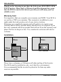
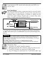
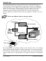
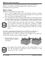
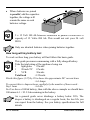
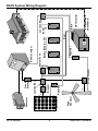
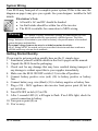
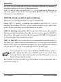
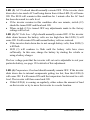
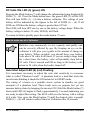
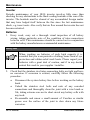
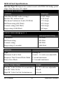
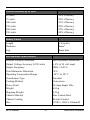
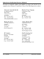
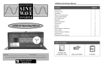
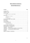
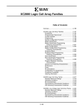
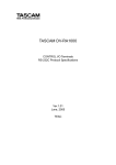
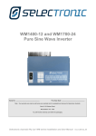
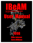
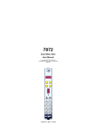
SE10 - 24 Volt Operating Manual
Serial No _____________________________ Purchase Date ______________
Note - Your 2 Year Warranty can only be valid once your
warranty card is completed and returned to Selectronic Australia
SELECTRONIC
AU S T R A L I A
SE10-24 Volt Owners Manual
Contents
Introduction
Warranty Card
Installation
Batteries and Connections
System Wiring
Getting Started Quickly
Parts Identification
Operation
STATUS Indicators
Voltmeter
Auto Start Setting
Low Voltage Shutdown Setting
Maintenance
Inverter
Batteries
Other System Components
Handy Hint
Radio Frequency Interference
Fault Finding
Product Warranty Conditions
Specifications
Selectronic Service Network
1
1
1-3
4-5
6-7
7
8
9
9-10
11
11-12
12
13
13
13-14
14
14
15
16
17
18-19
20
Legend for Symbols
Warnings and
electrician’s notes
z
Page No.
Hints and Pointers
Examples
Introduction
Thank you for choosing to purchase the Selectronic SE10 TRUE SINE
WAVE inverter. Many hours of Research and Development have gone
into the SE10 to ensure this inverter provides you with many years of
reliable service
Warranty Card
It is imperative that you complete your warranty card NOW. Your SE10 is
covered by a TWO year warranty. This warranty is in addition to your
rights under the trade practices act of your state or territory.
Returning you completed warranty card will enable us to register your
warranty and avoid any possible delays should service be required. If you
have any comments about our product that will not fit on the warranty card
please feel free to drop us a line. Yes, constructive criticism will also be
welcome.
Installation
200mm
200mm
200mm
200mm
SE10
Inverter
SE10 Inverter
Front
Please leave a clearance of 200mm on all sides and top of the Inverter.
The SE10 must be installed in a dry, cool, dust-free environment.
It is recommended that the inverter be placed as far from any radio
receivers as possible.
SE10 Manual
1
Selectronic Australia
Large amounts of DC current can be drawn by your SE10, care
must be taken.
Fixed Installation
All fixed installation battery connections must be securely bolted,
using stainless steel nuts and bolts. To protect the connection from
corrosion smear a small amount of Vaseline or similar over the
joint. Never place batteries directly onto a concrete floor, place
timber or similar material beneath the batteries.
*System Fuse
To electrician’s
Battery Bank
SE10
Inverter
Switchboard
RFI / Lightning
Earth
* A system fuse (of at least 20 Amps) should be placed before the battery.
An HRC motor start type is recommended. (See your system designer for
details).
Warning
As a matter of safety, Selectronic strongly recommend that all fixed
installations be designed and installed by appropriately qualified person. The Solar
Energy Industries Association in your state or territory can provide names of accredited
system designers and installers.
The output voltage from an inverter is as lethal as mains electricity.
All AC wiring MUST be carried out by an accredited electrician and must conform to
AS3000 and/or any relevant local standards.
Electrician’s Note
• All earth’s AC and DC should be bonded
• RFI/Lightning Earth stake should be within 3m of the inverter
• The SE10 is suitable for connection to MEN wiring
• Any AC changeover switch must be a ‘break before make’ type
SE10 Manual
2
Selectronic Australia
Portable Use
By using optional battery clips, the SE10 can be connected directly to a
vehicle battery. When using Alligator clips ensure they have a tight grip
around the battery post. Wherever possible battery connections should be
bolted. If connecting the SE10 through a cigarette lighter socket the
maximum power output of the SE10 will be severely restricted, this
practice should be avoided. Check with your supplier or installer if you are
unsure.
Do not use alligator clips in a moving vehicle
Start Battery
Earth (to chassis)
SE10 Inverter
Isolator
Vehicle
Alternator
Auxiliary Battery
Earth (to chassis)
By incorporating an auxiliary battery in the manner above, the starting
battery should remain charged for vehicle starting (see your auto electrician).
The SE10 has sufficient battery cable length to allow it to sit underneath the
vehicle whilst in use. If the ground is wet, place the SE10 on a waterproof
liner.
SE10 Manual
3
Selectronic Australia
Batteries and Connections
Batteries are the key to maximum performance from your SE10, if a
battery is too small or not fully charged it may result in de-rated
performance from your SE10.
Battery ratings
Batteries can be rated in one of two ways:
1. CCA = Cold Cranking Ability. This is the amount of power or current
that a battery can deliver for a short period, typically a few seconds. This
how a car battery would normally be rated.
2. Ah = Ampere Hours. This is the maximum amount of energy that can be
stored in a battery; this figure will generally be stated at a particular hour
rate. This is how a deep cycle or storage battery would normally be rated.
100Ah @100hr, this means that when this battery is discharged
over a period of 100 hours, the battery has a capacity of 100Ah.
This in theory means 1 Amp for 100 hours, although this would in
practice result in a totally discharged battery that may not then
recover.
To achieve maximum performance from your SE10 you must have a
battery capable of delivering 50 Amps for a short period whilst
maintaining at least 21 volts. To provide a 24 volt supply to your SE10 you
will need to join more than one battery together.
•
Where batteries are joined
in series, add the voltage of
each battery.
The capacity will equal the capacity of the smallest battery. 2 x 12
volt 100 Ah batteries connected in series would have a total
capacity of 24 Volts – 100 Ah.
SE10 Manual
4
Selectronic Australia
•
Where batteries are joined
in parallel, add the capacities
together, the voltage will
remain the same as each
batteries voltage.
2 x 12 Volt 100 Ah batteries connected in parallel would have a
capacity of 12 Volts–200 Ah. This would not suit your 24 volt
SE10.
Only use identical batteries when joining batteries together.
How long will my battery last
To work out how long your battery will last follow this basic guide.
This guide presumes commencing with a fully charged battery.
Take the total rating of the appliance being run
1
light globe
25watts
1
20 inch TV 67watts
1
VCR
30watts
Total load
=122watts
Divide this figure (122) by 20 to know the approximate DC current draw
=6.1Amps
To convert this to Ampere hours, multiply by the number of hours used Say 1 hour
=6.1Ah
So if we have a 100Ah battery, then with the above example we should have
100 minus 6.1 = 93.9 Ah remaining in the battery.
As a general guide never discharge a battery below 50%. The
deeper a battery is discharged on a regular basis, the less life you
can expect from the battery. See you battery specifications for full
details.
SE10 Manual
5
Selectronic Australia
SE10 Manual
6
Wind
Generator
Solar Panel
Generator
Circuit
Breaker
-
+
Regulator
-
+
Circuit Breaker
Junction Box
Circuit
Breaker
+
Battery Charger
Regulator
To electrician’s
switchboard
SE10 Inverter
Black -
Junction Box
Earth
Red +
Battery Bank (4 x 6V)
System Fuse
-
RAPS System Wiring Diagram
Selectronic Australia
System Wiring
Your SE10 may form part of a complete power system, If this is the case, the
diagram on page 6 may give you a guide. See your designer / installer for full
details.
Electrician’s Note
• All earth’s AC and DC should be bonded
• An Earth stake should be within 3m of the inverter
• The SE10 is suitable for connection to MEN wiring
Warning
As a matter of safety, Selectronic strongly recommend that all fixed
installations be designed and installed by appropriately qualified person. The Solar
Energy Industries Association in your state or territory can provide names of accredited
system designers and installers.
The output voltage from an inverter is as lethal as mains electricity.
All AC wiring MUST be carried out by an accredited electrician and must conform to
AS3000 and/or any relevant local standards.
Getting Started Quickly
If you want to get powered up quickly here are the 11 simple steps.
1. Familiarise yourself with the details in the first 6 pages on this manual.
2. Unpack the SE10 from the packaging.
3. Check unit for any damage that may have resulted during transport, if
any damage is evident report this to your supplier immediately.
4. Make sure the SE10 ON/OFF switch (12) is in the off position.
5. Connect battery positive wire (red) (10) to battery positive or battery
fuse.
6. Connect battery neg. wire (black) (11) to battery negative or battery fuse.
7. Plug a 230 - 240V appliance into inverter front power point (8) but do
not switch on.
8. Turn ON/OFF switch (12) to ON.
9. After 3 seconds LED (1) will begin to flash. If no LEDs light, check for
correct connection to battery.
10. Turn power point (8) on
11. You’re away.
SE10 Manual
7
Selectronic Australia
SE10 Manual
8
LED (6)
LED (5)
LED (3)
LED (4)
LED (1)
LED (2)
Auto Start Adjust
FLASHING
Alarms
FLASHING
1000 WATT SURGE
SE10
24 VOLT
(8) Power Point / GPO
PROUDLY DESIGNED & MADE IN AUSTRALIA
350 WATT CONT
DC TO MAINS POWER
S I N E WAVE I NVERTER
S E L E C T R O N I C
(7) Mode Button
Low
Volts Adjust
ON
DC Volts
ON
TEMP Overload
21.0
Power
DC Volts Low/High
22.0
AC Overload
23.0
STATUS
AC Volts ON
>24.0
DC
Volts
(12) ON/OFF Switch
(10) Battery Positive (red)
(9) Heatsinks
Battery Negative (black) (11)
SE10 Parts Identification
Selectronic Australia
Operation
Six LEDs are provided on the front panel to indicate a number of parameters,
and allow adjustment of some of these parameters.
LED (5) and (6) tells you what LED (1) – (4) is displaying as indicated on
the front panel of the SE10. Pressing Mode Button (7) will change the
information being displayed.
STATUS indicators LED (5) (green) flashing
When power is first applied LED (1) and (5) should flash.
When LED (5) (green) is flashing, this indicates the LED (1) – (4) is
showing the inverters STATSU, as per written notation to the right of the
LEDs. In this mode there are no adjustments to be made.
LED (1) Flashing indicated the SE10 is in Auto Start mode, this indicates
that no power is being drawn from the inverter so it has gone to SLEEP to
save power. If no power is used within 12 minutes, the LED (1) will flash at
a slower rate therefore saving more power.
LED (1) Stays ON, the inverter has been commanded to provide power to
the load (e.g. a light switch has been turned on) so it has gone from SLEEP
mode to ON. Once the load has been removed (e.g. the light switch is turned
off) the inverter will wait 10 seconds and return to SLEEP mode.
It is good practice to have your SE10 in SLEEP mode as often as
possible. When the SE10 is in SLEEP mode it uses 0.045 amps
from the battery, when the inverter is in the ON mode it uses at
least 0.3 amps from the battery.
The amount of power required to go from SLEEP to ON is adjustable and is
described on page 11.
SE10 Manual
9
Selectronic Australia
LED (2) AC Overload should normally remain OFF. If the inverter shuts
down due to too much AC load being drawn from it then LED (2) will come
ON. The SE10 will remain in this condition for 1 minute after the AC load
has been decreased to a safe level.
• If the inverter remains in this condition after one minute, switch (12)
should be turned OFF and then back ON.
• When switch (12) is turned OFF any adjustments made to the factory
settings will be lost.
LED (3) DC Volts Low / High should normally remain OFF. If the inverter
shuts down because the battery volts are too high then this LED (3) will
come ON. It will remain ON until normal battery volts are restored.
• If the inverter shuts down due to not enough battery volts, then LED (3)
will flash.
• LED (3) will continue to flash until the battery volts have risen
sufficiently. In this case, charge the battery by starting the vehicle or
using a battery charger.
The low voltage point that the inverter will cut out is adjustable to suit your
particular battery, see page 12 for details of this adjustment.
LED (4) Temperature Overload should normally remain OFF. If the inverter
shuts down due to internal components getting too hot, then this LED (4)
will come ON. It will remain ON until the temperature has lowered to a safe
level. The inverter will then come back ON.
• If this LED (4) is coming on regularly, either reduce the amount of load
on the inverter or try to move the inverter to a cooler location.
SE10 Manual
10
Selectronic Australia
DC Volts ON, LED (5) (green) ON
Pressing the Mode button (7) will change the information being displayed by
LEDs (1) – (4). Press the Mode button once, the green LED (5) will be ON.
This will turn LEDs (1) – (4) into a battery voltmeter. The voltage of your
battery will be indicated by the figures to the left of LEDS (1) – (4). If all
LEDs are ON then the battery voltage is greater than 24 Volt.
The LEDs will turn OFF one by one as the battery voltage drops. When the
battery voltage is below 21 volts, LED (4) will flash.
To return to Status, quickly press the mode button (7) once.
How to make use of a Voltmeter
Batteries vary enormously, in size capacity and quality and
can be severely affected by age. By keeping an eye on the
voltmeter it will give you a guide to the amount of charge in
your battery. Where possible, you should keep your battery
volts above 24 volts at all times. If you are using a large load
for a short time, the battery volts will probably drop below
24 volts. This is normal and OK as long as the battery volts
return to 24 volts when the load is turned off.
Auto Start Adjust LED (6) (red) Flashing
It is sometimes necessary to adjust the auto start sensitivity to overcome
what is called “Phantom Loads”. A phantom load is a load that tricks the
inverter into thinking it should be ON instead of in SLEEP mode.
The wiring of a house or a portable stereo system in standby are good
examples of a phantom load. These loads serve no purpose but yet can
increase battery drain by bringing the inverter ON. Hold the Mode button (7)
down until LED (6) begins to flash, (approximately 1 second) indicating you
are ready to adjust this setting. The SE10 will leave the factory with a setting
of 4 watts. Now press the Mode button (7) until the desired value is sought.
LEDs (1) – (4) will return to either Status or Voltmeter after 20 seconds.
SE10 Manual
11
Selectronic Australia
Indicator
Setting
LED (1) ON
LED (2) ON
LED (3) ON
LED (4) ON
ALL LEDs ON
16 watts
12 watts
8 watts
4 watts
Inverter will remain ON at all times. This could
be used if a fax machine or VCR is required to
stay on at all times. Be aware that this will use
more power from your battery.
Low Volts Adjust LED (6) (red) ON
To avoid total discharging of your battery the SE10 shuts down at a pre-set
low voltage. As all batteries are different, so too is the minimum voltage they
should be discharged to. The SE10 will leave the factory with a setting of
22.0 volts, change this setting if required.
Hold the Mode button (7) down until LED (6) comes ON, (approximately 2
seconds) indicating you are ready to adjust this setting. Now press the Mode
button (7) until the desired value is sought. LEDs (1) – (4) will return to
either Status or Voltmeter after 20 seconds.
Indicator
Setting
LED (1) ON
LED (2) ON
LED (3) ON
LED (4) ON
23.0 volts
22.0 volts
21.0 volts
20.0 volts
SE10 Manual
12
Selectronic Australia
Maintenance
Inverter
Periodic maintenance of your SE10 inverter involves little more than
checking for any obstructions to the black cooling heatsink at the rear of the
inverter. The heatsink must be cleared of any accumulated foreign matter
that may have lodged itself between the fins since the last maintenance
check, e.g. insect nests. Also verify that air flow around the inverter has not
become restricted.
Batteries
1. Every week, carry out a thorough visual inspection of all battery
wiring, taking particular note of the condition of inter-connections
between cells. This maintenance should be carried out in conjunction
with the battery manufacturers recommended maintenance.
Safety Hint
When working on batteries of such high capacity it is
essential that you wear protective clothing, some form of eye
protection and rubber-soled work boots. Please regard your
batteries with a great deal of caution, and if in any doubt,
entrust this work to your supplier / installer.
2.
Check that the stainless steel inter-connecting bolts are tight and have
no corrosion. If corrosion is evident, carefully follow the following
procedure.
•
•
•
Disconnect the system battery fuse before working on the battery
bank.
Unbolt the stainless steel bolts and nuts of any corroded
connections and thoroughly clean the joint with a wire brush or
file, taking extreme care not to short circuit any battery cells with
any tools.
Re-assemble and smear a small amount of Vaseline or similar
grease over the surface of the joint to slow down any future
corrosion.
SE10 Manual
13
Selectronic Australia
3.
Once a fortnight or as directed in your battery manufacturer, check the
specific gravity (SG) of each battery cell using a hydrometer, to ensure
that all cells are performing correctly and are properly charged. Any
serious imbalance should be reported to your system designer in case
remedial action needs to be taken.
Solar Modules
•
Periodically check for a build up of dust or any other foreign matter.
Wind Generator
•
As wind generators are mechanical devices that are subject to weather
variances, proper maintenance is essential for reliable service.
•
Carefully follow the manufacturers maintenance guidelines; if unsure
contact your supplier.
Handy Hints
It is very important that you become familiar with the
functioning of your inverter. From a distance, it is not always
easy to know what if the inverter is On or in Sleep mode. An
easy way to determine this is to plug a small child's night light
(neon type) into a power point that is easily visible, or replace
this power point with a safety type with a neon indicator. This
will indicate the inverter's operation by flashing when the
inverter is in SLEEP mode and remaining ON when the
inverter is brought ON by a load.
SE10 Manual
14
Selectronic Australia
Radio Frequency Interference
For many years, Radio Frequency Interference (RFI) has been an annoying
problem for owners of Inverters. RFI in a domestic situation can cause noise
on an AM radio receiver. The degree of interference can vary dramatically
from site to site. Below are a few suggestions to help reduce the effects of
RFI in your installation. It is not essential that you follow these guidelines,
however, they will give you the best chance of reducing any RFI, particularly
on AM radio.
It is recommended that the power system including the inverter be housed at
least 10 metres from the home.
Ensure a good earth stake is placed as close to the inverter as possible. This
earth stake should be in a moist area and should be connected to the inverter
earth, see page 2 for wiring details.
Avoid running DC cables into the home, if at all possible. If this cannot be
avoided, run DC and AC in separate conduits separated by as much distance
as practicable. All DC wiring should also be kept as short as possible.
Connect battery negative to earth.
AM radios should be powered from their own self contained batteries and
kept as far away as possible from AC or DC wiring within walls. Make sure
that your AM radio has maximum signal strength. This will help your radio
to reject any unwanted noise being produced by your inverter, regulator,
controllers or DC lighting. If possible, try moving the radio around to
improve the signal strength or use an external aerial. Some of today's
building materials such as steel roofs and foil insulation may form a barrier
to incoming radio signals. If an external aerial is required, it should be on the
outside of the home, mounted as high as practicable and as far from the
inverter as possible. Connection from the aerial to the radio should be via a
low loss coaxial cable.
Please note the aerial must be an AM RADIO type; a TV aerial will
not work.
SE10 Manual
15
Selectronic Australia
Fault Finding
No indicators ON when power is first applied
When first connected, if the SE10 shows no indicators the battery
connections may be reversed. Check that the red battery wire (10) is
connected to the battery positive, and the black battery wire (11) is connected
to the battery negative. Remember there is a 3 second delay before power is
available after switch ON.
Inverter stays ON when no appliance is being used
This can be a common problem known as a “Phantom Load”, but can be
easily overcome. Some appliances will need to be switched off at the power
point as they may still represent a small load despite being switched off at
the appliance.
Check again to make sure that there are no appliances left ON, the
sequentially switch off appliances at the wall and by watching your night
light (as described in Handy Hint, check to see if the SE10 returns to pulsing
(SLEEP) mode after a 10 second delay. Once you have found the offending
appliance, increase the sensitivity of the “Auto Start” (see page 11) until the
inverter turns OFF. Once this is done re check that small loads will still bring
the inverter ON when required.
Inverter shuts down during the middle of the day, and comes
back ON late in the afternoon
This is more than likely caused by high battery volts during peak charging
times from Solar Panels. Battery volts should never exceed 34 volts. If this is
the case, have your Solar Regulator checked.
Warning
As a matter of safety, Selectronic strongly recommend that all fixed
installations be designed and installed by appropriately qualified person. The Solar
Energy Industries Association in your state or territory can provide names of accredited
system designers and installers.
The output voltage from an inverter is as lethal as mains electricity.
All AC wiring MUST be carried out by an accredited electrician and must conform to
AS3000 and/or any relevant local standards.
SE10 Manual
16
Selectronic Australia
Product Warranty Conditions
Selectronic Australia Pty Ltd warrants your SE10 inverter to be free
from defects in materials and workmanship under normal use and
service, for an initial period of two (2) years.
This warranty is applicable only from the date of original purchase.
All parts will be replaced or repaired free of charge within this
period. Travelling time for field service personnel is not covered
under this warranty. If no authorised field service personnel are
available, the unit shall be returned to any authorised service centres,
this must be done at the owner’s cost. There will be no charge for the
return of the inverter. Repairs carried out by unauthorised service
centres will not be covered under warranty.
In the event of unauthorised exporting, Selectronic reserve the right
to refuse warranty claims outside Australia or New Zealand.
The provision of this warranty shall not apply if the unit has been
subject to misuse, neglect, acts of God, accidental damage or has
been used for a purpose for which it is not designed.
Charges to the point of purchase and the cost of any repairs resulting
from damages occurring during this freighting will be borne by the
owner. Any alterations or repairs by unauthorised parties will void
your warranty.
To ensure fast efficient handling of any warranty claims, please
complete and return your reply paid warranty card within 30 days
from date of purchase.
SE10 Manual
17
Selectronic Australia
SE10 24 Volt Specifications
Inverter Type Microprocessor control circuit with PWM full bridge power
stage. True sine wave AC output
Current draw from Battery
Condition
Amperage
Auto Start SLEEP mode (average)
Inverter ON, with no Load
Maximum Continuous Load (350 Watt)
Half hour rating (450 Watt)
5 minute rating (600 Watt)
Surge rating (1000 Watt)
0.045 Amps
0.30 Amps
17.5 Amps
22.5 Amps
30.0 Amps
50 Amps
Inverter Power Ratings @ 25º C
Condition
Total Appliance Rating
Continuous
Half hour rating
5 minute rating
Surge rating (5 seconds)
350 Watt
450 Watt
600 Watt
1000 Watt
Auto Start
Type
Minimum Load to Start
Response Time Normal Pulse Mode
Power Save Mode
Pulsing AC
4 watts – 16 watts user adjustable
1 second maximum
1.5 seconds maximum
Battery Voltage Range
Voltage
Low DC Volts Cut Out–10 second delay
Low DC Volts Cut In
High DC Volts Cut Out–Instantaneous
20 – 23 volts user adjustable
24 volt
34 volts
SE10 Manual
18
Selectronic Australia
Inverter Efficiency @ 24 volts
40 watts
75 watts
100 watts
150 watts
260 watts
350 watts
88% efficiency
89% efficiency
91% efficiency
89% efficiency
87% efficiency
84% efficiency
Battery Cables
Length
Diameter
Lug
1.6 metres
8mm2
8mm hole
Miscellaneous Specifications
Reverse Polarity Protection
Output Voltage Accuracy 0-350 watts
Output Frequency
Total Harmonic Distortion
Operating Temperature Range
Transformer Type
Cooling Method
Power Point
Weight
Shipping Weight
Chassis Material
Chassis Coating
Size
SE10 Manual
19
Full Electronic Protection
± 4% @ 24 volt input
50Hz ± 0.01%
<4%
-10º C to 50º C
Toroidal
Convection
10 Amp Single Pole
4.6 kg
5.2 kg
Zinc Coated Steel
Powder Coated
176W x 122H x 260mm D
Selectronic Australia
Selectronic Authorised Service Network
If service is required, contact your supplier or return your inverter in its
original carton with proof of purchase to any of the following service centres.
Selectronic Australia Pty Ltd
25 Holloway Drive
Bayswater
Victoria 3153
Australia
Ph: 03 9762 4822
Fax: 03 9762 9646
[email protected]
Rainbow Power Company
1 Alternative Way
Nimbin
NSW 2480
Australia
Ph: 02 6689 1430
Fax: 02 6689 1109
Burley TV Service
278 Edmondson Ave.
Austral
NSW 2171
Australia
Ph: 02 9606-0279
Amelec Marine Sales
16 Parkinson Lane
O’Connor
WA 6163
Australia
Ph: 08 9331 3100
Fax: 08 9331 5150
[email protected]
RF Analysis
Harness Cask Road
Dorrigo
NSW 2453
Australia
Ph: 02 6657 8003
Fax: 02 6657 8002
Reid Technology Ltd
3-5 Auburn Street
Takapuna
North Shore City
Auckland
NZ
Ph: 9 489-8100
Fax: 9 489-8585
[email protected]
SE10 Manual
20
Selectronic Australia
Notes:
SE10 Manual
21
Selectronic Australia
SELECTRONIC
AU S T R A L I A
25 Holloway Drive Bayswater, Victoria 3153 Australia
Phone 03 9762 4822 Fax 03 9762 9646 Email [email protected]
Part No ST-M-SE102 REV-3 9/8/2000
SE10 Manual
22
Selectronic Australia