1
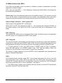
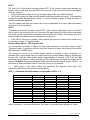
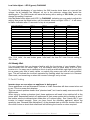
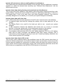
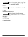
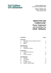
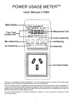
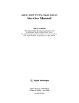
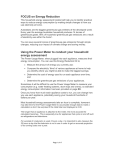
WM1400-12 and WM1700-24 Pure Sine Wave Inverter Serial No _____________________________ Purchase Date ____________________________ Note - Your warranty can only be valid once your warranty card is completed and returned to Selectronic Australia Suite 5, 20 Fletcher Road Mooroolbark VIC 3138 You will find the warranty card within the packaging Selectronic Australia Pty Ltd WM series Installation and User Manual Doc:CS0132_06 TABLE OF CONTENTS 1. Introduction .........................................................................................................................3 2. Warranty Card .....................................................................................................................3 3. Installation ...........................................................................................................................3 3.1 System Diagram ..............................................................................................................4 3.2 Installation Example ........................................................................................................4 3.3 System/Battery Fuse .......................................................................................................5 3.4 Batteries...........................................................................................................................5 3.5 Connection & AC Wiring .................................................................................................6 4. Operation .............................................................................................................................7 4.1 Demand Start ..................................................................................................................7 4.4 Handy Hint .....................................................................................................................10 5. Fault Finding .....................................................................................................................10 6. System Maintenance ........................................................................................................12 6.1 WM Inverter Maintenance .............................................................................................12 6.2 Battery Maintenance .....................................................................................................12 7 Radio Frequency Interference ..........................................................................................13 8 Serial Port Wiring..............................................................................................................13 8.1 Keypad Wiring ...............................................................................................................14 8.2 Keypad Front Panel.......................................................................................................14 8.3 Readings (Keypad Grey Keys) ......................................................................................14 8.4 Handy Hint .....................................................................................................................15 8.5 Settings (Keypad Light Blue Keys) ................................................................................15 8.6 Options ..........................................................................................................................16 8.7 Diagnostics ....................................................................................................................17 8.8 Inverter Alarms ..............................................................................................................17 9. WM1400-12 / WM1700-24 Electrical Specifications ......................................................18 10. Mounting Template.........................................................................................................19 11. Warning ...........................................................................................................................19 12. Product Warranty and Conditions ................................................................................20 13. Selectronic Authorised Service Network .....................................................................21 Selectronic Australia Pty Ltd WM series Installation and User Manual Doc:CS0132_06 1. Introduction Thank you for your purchase of a WM Series Selectronic Sine wave inverter. Your WM Inverter is a state-of-the-art high performance “True Sine Wave” DC-AC Inverter. Many hours of development time have been invested in the WM Series so that we can provide you with a reliable high quality inverter. The output from your WM Series inverter is as good as, if not better than mains power. If looked after properly, the WM Inverter will give you many years of reliable service. 2. Warranty Card Before proceeding any further, it is extremely important that you complete your warranty card NOW. This will enable us to immediately register your 5 year warranty period. By accurately completing your warranty card, you will provide us with valuable information that will assist us in keeping up with your alternative energy needs. Please take a few moments to fill in the warranty card. Your efforts will be greatly appreciated. 3. Installation The installation of your inverter is extremely important. Failure to follow the recommended installation instructions may void your warranty. If in doubt, ask your supplier/installer. Installation should only be performed by suitably qualified personnel. AC wiring can only be carried out by licensed electricians. After unpacking, check for any damage that may have occurred during transit. Should you observe are any signs of damage, contact your supplier immediately. The Inverter must be installed in a dry, cool, well ventilated and dust-free environment. Please leave at least 300mm clearance around the sides and top of the Inverter and approximately 200mm at the base as this will aid the natural cooling of the Inverter. The air vents on the underside of the WM Inverter also need to be kept clear of obstructions. 300mm 30mm Wall Minimum 300mm 160mm ON DEMAND START STATUS 16 Watts AC Volts ON AC Overload 12 Watts 8 Watts DC Volts Low/High 4 Watts TEMP Overload Demand Start Adjust Of f DC POWER DC TO AC POWER Alarm s Low Volts Adjust Mod e PROUDLY DESIGNED & MADE IN AUSTRALIA 385mm BAS E Page 3 WM series Installation and User Manual Doc:CS0132_06 In a household situation we suggest that you house your Inverter and other power generating equipment in a purpose built shed sited remotely from the home, and as far away as possible from any radio transmitters or receivers. Also make sure that the exhaust from your generator or other sources of heat or fumes are kept well away from the WM Inverter. Any inverter mounted under a single skin metal roof is unacceptable, as condensation may form under the roof and drip onto the inverter. You must have a suitable battery bank (12V DC for WM1400-12 and 24VDC for WM170024) that is maintained and operated to the battery manufacturer’s recommendation. To ensure operation to WM specification, the battery bank should have a minimum capacity. See table 3a. (Ask your supplier if in doubt). Smaller capacity batteries can be used but may result in degraded performance of the WM Inverter under heavy surge conditions. Table 3a Suggested minimum battery size WM 1400 240Ah WM1700 160Ah 3.1 System Diagram Regulator Battery Charger Battery Bank Regulator 3.2 Installation Example Main Switch Earth Leakage CB A N E ELCB Protected Circuits Fuse / CB System Fuse RFI Ground + -+ - Page 4 Both positive and negative poles of the battery must be fused unless one pole is earthed. Consult your system designer installer. A N E Mains Earth Batter Bank + y WM series Installation and User Manual Doc:CS0132_06 3.3 System/Battery Fuse A system fuse is an extremely important part of any power system, this fuse is designed to give one point of complete disconnect in case of a serious fault. The fuse should have a sufficient rating so as not to blow under heavy load conditions. Your inverter will normally be the biggest load in your system, if this is the case a motor start fuse equal to or slightly higher than the maximum continuous current of the inverter should be used. As a guide we suggest 160Amp motor start fuses for 12volt systems and 100A for 24volt systems. These sizes may have to be increased depending on other components in the system. If in any doubt see your supplier or installer. 3.4 Batteries Batteries are very dangerous. Please read the safety information provided by the battery supplier. Battery acid is dangerous. Batteries can emit hydrogen gas, which is explosive. Batteries connected in series can produce hazardous voltages. Disconnecting a DC power connection (even on one battery cell) can cause dangerous highenergy DC arcs, which can cause serious burns and eject hot particles, and can be difficult to extinguish. Disconnecting a DC power connection (even on one battery cell) can cause renewable sources to produce large voltages (much larger than the battery voltage) on battery terminals and DC wiring. Such voltages can be lethal. They can also damage the WM Inverter. Only suitably trained and qualified personnel should disconnect any DC power connection, including battery cell connections, and only with suitable procedures and safety precautions. The length of cable from the inverter to the battery should not exceed 2 meters in length, longer cable runs may result in reduced performance. Both positive and negative battery cables should be run together. Cables should be no more than 50mm apart Diagram 3.4a Min 500m Battery fuses Battery fuses 2m max Battery Bank Page 5 WM series Installation and User Manual Doc:CS0132_06 3.5 Connection & AC Wiring Before making any wiring connections, check that the main DC switch on the front panel is in the OFF position, i.e.; LEVER DOWN. Your electrician should firstly connect the AC wiring via the three terminal junction box. Hardwiring to the integral junction box will provide a more reliable, long term connection as opposed to plugging in to a power point. Carefully observe the correct connections. Please refer to the installation diagram 3.4a. N EA RATINGS LABEL SERIAL JUNCTION BOX Base Panel BROWN ACTIVE GREEN/YELLOW EARTH BLUE NEUTRAL (red dot, right connector) (E, centre connector) (left connector) The lid of the junction box has knockouts to allow conduit entry. Make sure this connection is tight and safe. Re fit junction box cover. NOTE: All AC wiring must be carried out by a licensed electrician and must conform to wiring regulations, or relevant wiring standards. Verify that the DC switch on the front panel is in the OFF position, (down). Connect the battery cables. RED BATTERY POSITIVE (+) BLACK BATTERY NEGATIVE (-) These connections should be tight. If using nuts, bolts and washers, they should be stainless steel. At this point re-check the connections before proceeding any further. WARNING: If the WM Inverter emits a very loud tone, the battery leads have been connected in reverse polarity. Immediately disconnect the leads and reconnect with the correct polarity. Do not under any circumstances; turn on the inverter DC switch when the buzzer is sounding, as permanent damage to the WM inverter will result. If all is well you can now turn the DC switch ON (up). Page 6 WM series Installation and User Manual Doc:CS0132_06 ON DEM AND START STATUS 16 Watts AC Volts ON 12 Watts AC Overload 8 Watts DC Volts Low/High 4 Watts TEMP Overload Demand Start Adjust Off DC ER DCPOW Switch DC TO AC Alarms Low Volts Adjust Mode PRO UDLY D ESIG NED & Front Panel 4. Operation 4.1 Demand Start When you first apply power, the WM Inverter will be in “Demand Start” mode, there will be a quiet pulsing sound. The WM Inverter is now ready for use. Demand Start mode means that the WM Inverter is producing pulses of power to sense when an appliance is switched on. The Demand Start feature allows the inverter to automatically turn on and off as the load requires. When all appliances are switched off, the inverter will return to Demand Start mode after approximately 10 seconds. This feature is extremely important as it conserves valuable battery power when no appliances are on. The amount of power or load that the Inverter needs to “start up” is adjustable, see “Demand Start Adjust”. 4.2 Demand Start Override In this mode the Inverter will be on at all times regardless of whether appliances are connected or not. This situation is useful if you have small loads such as a DVD player or digital clock that requires 24 hour power, or if loads are too small to be sensed in the Demand Start mode. The only disadvantage is that when the appliances are off the WM Inverter will be drawing more power than it would in Demand Start mode. DEMAND START 12 Watts 8 Watts 4 Watts Demand Start Adjust Low Volts Adjust Mod e Page 7 LED 1 LED AC Overload 2 DC Volts Low/High LED TEMP Overload 3 LED Alarms 4 LED 5 Mode Button STATU S Volts ON AC 16 Watts WM series Installation and User Manual = LED is on = LED is flashing = LED is off Doc:CS0132_06 4.3 Mode button and LED’s Five LED’s are provided on the front panel to indicate a number of parameters, and allow adjustment of some of these. LED 5 tells you what LED 1 – 4 are displaying. Pressing the Mode Button will change the information being displayed. Please note: Once the parameters have been successfully entered, if the inverter is turned off or the DC power is disconnected from the inverter, the parameters which have been entered will be saved and held in permanent memory and will not need to be re-entered. Status & Alarm indicators – LED 5 (green) OFF When power is first applied LED 1 should flash. When LED 5 is OFF, this indicates the LED (1) – (4) is showing the inverters STATUS, as per written notation to the right of the LED’s. In this mode there are no adjustments to be made. LED 1 Flashing This indicates the WM inverter is in Demand Start mode. Insufficient power is being drawn from the inverter so it has gone to SLEEP to save power. LED 1 Stays ON The inverter has been commanded to provide power to the load (e.g. a light switch has been turned on) so it has gone from SLEEP mode to ON. Once the load has been removed (e.g. the light switch is turned off) the inverter will wait 10 seconds and return to SLEEP mode. It is good practice to have your WM Inverter in SLEEP mode as often as possible. When the WM Inverter is in SLEEP mode it uses 1/10th from the battery. When the inverter is in the ON mode it uses at least 0.6 amps from the battery. The amount of power required to go from SLEEP to ON is adjustable and is described see below in “Demand Start Adjust”. LED 2 AC Overload should normally remain OFF. If the inverter shuts down due to too much AC load being drawn from it then LED 2 will come ON. The WM Inverter will remain in this condition for 2 minutes after the AC load has been reduced to a safe level. LED 2 will flash if the inverter shuts down due to “time to shutdown”, see page 11. If the WM inverter remains in this condition after two minutes, the main DC Power Switch should be turned OFF and then back ON. Page 8 WM series Installation and User Manual Doc:CS0132_06 LED 3 DC Volts Low / High should normally remain OFF. If the inverter shuts down because the battery volts are too high then this LED will come ON. It will remain ON until normal battery volts are restored. If the inverter shuts down due to not enough battery volts, then LED 3 will flash. LED 3 will continue to flash until the battery volts have raised sufficiently. To remedy this charge the battery by starting the vehicle, or using a battery charger or allow the solar or wind to recharge the batteries. The low voltage point that the inverter will cut out is adjustable to suit your particular battery see below “Low Volts Adjust”. LED 4 Temperature Overload normally remains OFF. If the inverter shuts down due to the black fins on top of the unit getting too hot, then this LED will come ON. If the inverter shuts down due to an internal component overheating, then this LED will FLASH. The inverter will come back ON when the temperature has lowered to a safe level. If this LED is coming on regularly, either reduce the amount of load on the inverter or try to move the inverter to a cooler location. Demand Start Adjust – LED 5 (green) ON It is sometimes necessary to adjust the auto start sensitivity to overcome what is called “Phantom Loads”. A phantom load is a load that tricks the inverter into thinking it should be ON instead of in SLEEP mode. The wiring of a house or a portable stereo system in standby is good examples of a phantom load. These loads serve no purpose but can increase battery drain by bringing the inverter ON. Hold the Mode button down, (approximately 1 second), LED 5 will turn ON indicating you are ready to adjust this setting. The WM Inverter will leave the factory with a setting of 4 Watts. Now press the Mode button until the desired value is sought. LED’s 1 – 4 will return to Status Indication after 10 seconds if a key is not pressed. Each press of the Mode button will increment the Demand Start level. The adjustment starts from the previously stored setting. LED 1 – 4 Demand Start Adjustment is indicated by LED’s 1- 4 Demand Start Wattage 4 Watts 5 Watts 6 Watts 7 Watts 8 Watts 9 Watts 10 Watts 11 Watts 12 Watts 13 Watts 14 Watts 15 Watts 16 Watts Continuous LED 1 Slow flash Medium flash Fast flash ON ON LED 2 Slow flash Medium flash Fast flash ON ON ON ON ON LED 3 Slow flash Medium flash Fast flash ON ON ON ON ON LED 4 ON ON ON ON ON After “continuous”, the next button press “rolls back” the demand start setting to 4 Watts Page 9 WM series Installation and User Manual Doc:CS0132_06 Low Volts Adjust – LED 5 (green) FLASHING To avoid total discharging of your battery the WM inverter shuts down at a pre-set low voltage. As all batteries are different, so too is the minimum voltage they should be discharged to. The WM inverter will leave the factory with a setting of 22.0 Volts; you may change this setting if required. Hold the Mode button down until LED 5 is FLASHING, indicating you are ready to adjust this setting. Now press the Mode button until the desired value is sought. LED’s 1 – 4 will return to Status Indication after 10 seconds if a key is not pressed. Low Volts Cut-out 20.0 Volts 20.2 Volts 20.4 Volts 20.6 Volts 20.8 Volts 21.0 Volts 21.2 Volts 21.4 Volts 21.6 Volts 21.8 Volts 22.0 Volts 22.2 Volts 22.4 Volts 22.6 Volts 22.8 Volts 23.0 Volts LED 1 Slow flash Medium flash Fast flash Fastest flash ON LED 2 Slow flash Medium flash Fast flash Fastest flash ON ON ON ON ON LED 3 Slow flash Medium flash Fast flash Fastest flash ON ON ON ON ON LED 4 ON ON ON ON ON After “23.0 Volts”, the next button press “rolls back” the Low DC Volts Cut-out setting to “20.0 Volts” 4.4 Handy Hint It is very important that you become familiar with the functioning of your Inverter. Since most Inverters are not within sight, it is not always easy to know what STATUS your inverter is in. An easy way to determine this is to plug a small child's night-light (neon type) into a power point that is easily visible, or replace any power point with a neon indicator type. This will indicate the inverter's operation by flashing when the inverter is in Demand Start mode; and remaining on when the inverter is brought on by a load. 5. Fault Finding Inverter stays on even when no appliance is being used. Some appliances such as Microwave Cookers or Video Recorders still draw current when not in use. This is to power their displays. This is a common problem known as a "phantom load", but it can be easily overcome with the WM inverter When trying to isolate a phantom load, these appliances will need to be switched off at the power point. Sequentially switch off appliances at their power points while checking to see if the inverter returns to demand start mode after a 10 second delay. See “Handy Hint” if your inverter is located remotely. Once you have found the offending appliance, adjust the sensitivity (see “Demand Start Adjustment”) of the demand start up until the Inverter turns off. Once this is done re-check that small loads will still bring the Inverter on when required. Page 10 WM series Installation and User Manual Doc:CS0132_06 Inverter will not come on when a small appliance is switched on This means that your demand start sensitivity is set too high. With the appliance in question switched on, adjust the demand start sensitivity (see "Demand Start Adjustment”) until the WM inverter turns on. Inverter shuts down during the day and comes back on late afternoon This is more than likely caused by high battery volts during peak charging times from solar panels. Battery volts should never exceed 34 volts for a 24V battery bank and 17 Volts for a 12V battery bank. If this is the case, have your Solar Regulator checked. This could be potentially dangerous so we advise you to consult your system designer immediately. Inverter shuts down with low volts. If your WM inverter has shut down because of low DC volts it could be due to the following: (1) A sustained large load could be causing the battery volts to drop below the cut out voltage. (a) The Battery Bank is too small for the loads you wish to use - consult your system designer. (b) A bad connection between the batteries and inverter due to a loose or corroded terminal. In this case, please refer to the maintenance section of this manual. (c) One or more battery cells could be faulty - consult your battery supplier. (2) If your battery volts are below 24.0V for a 24V battery bank and 12.0V for a 12V battery bank with no loads connected, the batteries most likely require charging. Use a hydrometer to check the specific gravity of each cell. Consult your battery manual for the correct specific gravity (SG) readings. Inverter shuts down due to HS too hot This is likely under sustained heavy load conditions since the WM inverter shuts down to protect its internal components. If you believe that the load is not excessive, check around the Inverter case and heatsink for obstructions to airflow as this will cause the Inverter to heat up much quicker and shut down sooner than normal. Also check that the clearances around the WM inverter are as specified in the INSTALLATION section of this manual. Page 11 WM series Installation and User Manual Doc:CS0132_06 6. System Maintenance To get the optimum performance from your WM inverter, particularly under heavy appliance loads, it is essential that the battery bank and the DC wiring all be in good condition. The small amount of time spent on the maintenance tasks below will maximise the reliability of your system. 6.1 WM Inverter Maintenance Periodic maintenance of the WM inverter involves little more than checking for unobstructed operation of the cooling fans, which are located on the sides of the inverter. Note that cooling air is drawn in through the vents in the side of the inverter. Suggested inverter maintenance should include: Check for unobstructed fan operation: Clear away any dust or foreign matter from the fan grill using a soft bristled brush. (Do not direct high-pressure compressed air at the fan blades) Note that the fan is designed to come on during heavy power demand. Check between fins of the heatsink Clean out any accumulated foreign objects, for example, insect nests, dust build up etc. 6.2 Battery Maintenance IMPORTANT: When working on batteries of such high capacity it is essential that you wear protective clothing, some form of eye protection and rubber soled work boots. Please regard your batteries with a great deal of caution, and if in any doubt, entrust this work to your installer. Visual inspection Every week, carry out a thorough visual inspection of all battery wiring, taking particular note of the condition of inter-connections between cells. Check Bolts Check that the stainless steel inter-connecting bolts are tight and have minimal corrosion. If corrosion is evident, carefully follow the following procedure. (a) Disconnect the system battery fuse before working on the battery bank. (b) Unbolt the stainless steel bolts and nuts of any corroded connections and thoroughly clean the joint with a wire brush or file, taking extreme care not to short circuit any battery cells with any tools. (c) Re-assemble and smear a small amount of Vaseline or similar grease over the surface of the joint to slow down any future corrosion Specific Gravity (for flooded batteries only) Every month or as directed in your battery instruction manual, measure the specific gravity (SG) of each cell using your hydrometer, to ensure that all cells are performing correctly. Any serious imbalance should be reported to your system designer in case remedial action needs to be taken. Page 12 WM series Installation and User Manual Doc:CS0132_06 7 Radio Frequency Interference Radio Frequency Interference (RFI) can be a problem for owners of inverters. RFI in a domestic situation may produce noise or interference on a radio or TV receiver. Considerable development time has resulted in a reduction of the RFI generated by the inverter to a level that complies with C-tick requirements. Compliance to this standard means RFI is low, but how well the inverter performs in a particular installation can vary. Below are some suggestions to help reduce the effects of RFI in your installation; It is recommended that the power system, including the inverter, be housed at least 15 metres from the home. Ensure an earth stake is placed as close to the inverter as possible and connected to the inverter via a short length of wire. See the “INSTALLATION” section of this manual for wiring. Avoid running DC cables into the home, if at all possible. If this cannot be avoided, run DC and AC in separate conduits separated by as much distance as practicable. All DC wiring cables should be kept together and be as short as possible. If your inverter is to be installed in a Mobile Home or similar, try to keep your inverter at least one metre away from your radio or audio equipment. The further the better. Using a Selectronic Keypad with a WM Inverter 8 Serial Port Wiring Using the RJ45 serial port on the bottom of the inverter, it is possible to connect an optional Remote LCD to your WM inverter. The remote LCD can be placed up to 100m from the inverter and can provide easy access to inverter and system information. To obtain this part, order P/No SA-KP-03 from your supplier. Serial Port Pin Number 1 2 3 4 5 6 7 8 Page 13 Data Cable Wire Colour Function White with green stripe Transmit + Green Transmit White with orange stripe Receive + Blue +15V White with blue stripe 0V Orange Receive White with brown stripe Brown RATINGSLABEL WM series Installation and User Manual Serial Port 8 1 Doc:CS0132_06 8.1 Keypad Wiring Keypad (from rear) 8 7 6 5 4 3 2 1 1 2 3 4 5 6 Serial Port (RJ45 located on base of the inverter) 8.2 Keypad Front Panel (Display not shown for clarity) Energy Managem ent MkII Rem ote Keypad ALARM INVERTER STATUS TIME BATTERY READINGS AC LOAD READINGS INPUT READINGS GENERATOR CONTROL CURRENT SHUNT 1 CURRENT SHUNT 2 CURRENT SHUNT 3 SETTINGS OPTIONS DIAGNOSTICS Keypad Light Blue Keys NEXT DISPLAY UP DOWN Keypad Dark Blue Keys Keypad Grey Keys 8.3 Readings (Keypad Grey Keys) The displays provide the following information: Press the indicated Keypad Grey Key. Battery readings DC Volts:27.4V --- Readings --- Displays the DC Battery volts. This provides you with an indication of the condition of your battery bank. AC Load readings AC Volts : 240V --- Readings --- Page 14 This reading gives an indication of the AC voltage produced by the inverter. This reading will vary depending on how large a load is connected or if the battery voltage is very low. Pressing the AC LOAD READINGS button again will move you to the next “AC Amps” screen. WM series Installation and User Manual Doc:CS0132_06 AC Load readings (second button press) The AC Amps reading shows the total current drawn from the AC output by the appliances connected to the inverter. This reading is also handy for knowing how much power a particular appliance draws. Pressing the AC LOAD READINGS button again will move back to the previous “AC Volts” screen. AC Amps : 2.5A --- Readings --- Other keypad grey keys Not Installed Pressing any of the keys “TIME”, “GENERATOR CONTROL”, “INPUT READINGS”, “CURRENT SHUNT 1”, “CURRENT SHUNT 2”, “CURRENT SHUNT 3”, will result in this screen being displayed. The functions are not available on the WM Inverter 8.4 Handy Hint To determine the total watts your inverter is supplying, multiply the AC Volts x AC Amps. I.e.: in the above example 240 x 2.5 = 600 watts. 8.5 Settings (Keypad Light Blue Keys) Press the Keypad SETTINGS Light Blue Key, then the ENTER Dark Blue Key. Please note: Once the parameters have been successfully entered (i.e. you have stepped right through the set parameters menu) then if the inverter is turned off or the DC power is disconnected from the inverter, the "parameters" which have been entered will be saved and held in permanent memory. Keypad Buzzer Buzzer : ON -Set Parameters- This display allows you to select whether the keypad audio alarm will sound during an overload or other alarm condition. Use the UP or DOWN keys to toggle between ON or OFF state. This is set to ON at the factory. DS Sense DS Watts :12W -Set Parameters- Demand Start: When in STANDBY mode the inverter will require a load of 4 watts or greater to turn on to full 240V power. This setting can be adjusted between 4 to 16 watts. In most cases the default setting of 4W will be suitable. If the inverter remains on continuously, increase this value until inverter goes into demand start (pulsing mode). You may need to try a few different settings to find the most appropriate value for your installation. Use the UP or DOWN keys to change this value. LO DC Volts Lo DC Volts:22.0 -Set Parameters- The WM inverter will cut out and a message will be displayed if the battery voltage falls below this setting for more than 10 seconds. The inverter will restart if reset, or when the battery volts rise above 24.0V for WM1700 and 11.5V for WM1400. Use the UP or DOWN keys to change the value. Default values are 22.0 volts for 24V operation and 11.0 volts for 12V operation. AC Output VOLTS Page 15 WM series Installation and User Manual Doc:CS0132_06 AC Volts : 240V -Set Parameters- Allows the AC output voltage to be set in a range of 220V to 240V if an output voltage other than 240V is required. Users outside Australia should check with their system designer for the correct setting. Use the UP or DOWN keys to change the value. This value is set to 240V at the factory. End Settings -End-Set Parameters- Indicates the end of the set parameters menu. Press any grey keypad key to return you to the STATUS menu. Your settings will be automatically saved. 8.6 Options (Keypad Light Blue Keys) Press the Keypad OPTIONS Light Blue Key. This display allows access to logged alarms. Press the OPTIONS key to scroll through logged alarms. If there are no logged alarms, only this screen will be displayed. When in this END ALARMS screen, press any grey keypad key to return you to the STATUS menu. -END--Alarms-- Logged alarms are: Low DC Volts High DC Volts AC Current Overload Current Limit High Transformer Temperature High Heatsink Temperature Page 16 WM series Installation and User Manual Doc:CS0132_06 8.7 Diagnostics (Keypad Light Blue Keys) Press the Keypad DIAGNOSTICS Light Blue Key. The following screens allow the user to look at various internal inverter values. These are not able to be changed from the keypad. Press the NEXT key to access diagnostics screens Press NEXT key ..Diagnostics.. This diagnostic number relates to the transformer temperature. Note the reading is NOT in degrees Celsius. Tx Temp.: 1 ..Diagnostics.. HS Temp: 53C ..Diagnostics.. Indicates Heatsink temperature. Note the reading IS in degrees Celsius. D/S I: 2 ..Diagnostics.. This diagnostic number relates to the Demand Start current level. Indicates the Inverter model, microprocessor code revision and year. Press any grey keypad key to return you to the STATUS menu. Selectronic C WM1700 1.00 2000 8.8 Inverter Alarms Inverter Alarms are not indicated on the keypad screen. The status of the inverter can be checked, along with the output voltages and currents. The Keypad LED will flash and the buzzer will sound on an Inverter Alarm. Page 17 WM series Installation and User Manual Doc:CS0132_06 9. WM1400-12 / WM1700-24 Electrical Specifications Inverter Type PWM Full Bridge power stage, with true sine wave AC output. SELECTRONIC WM INVERTER SPECIFICATIONS ELECTRICAL PARAMETER Output Power @ 25 °C Ambient WM1400 1,400 watts 1,800 watts 3,600 watts 1,200 watts 1,600 watts 3,600 watts 10 - 17V DC 0.05A DC 0.7A DC 136A DC 349A DC Output Power @ 40 °C Ambient Voltage Input Range Input Current Demand Start Sensitivity Response Time Factory Setting Low Voltage Shutdown High Voltage Shutdown Low Voltage Shutdown Output Voltage Output Current Page 18 20 - 34V DC 0.05A DC 0.6A DC 80A DC 212A DC 4-16W 1 Second Max 4W 10 – 11.5V DC 20 – 23.0V DC 17V DC 34V DC 11.0V DC 22.0V DC 240V AC +/- 4% 7A AC 18.75A AC 5.8A AC 15A AC Output Wave Shape Output Frequency Total Harmonic Distortion Efficiency Power Factor Limitations Input / Output Isolation Memory Retention Operating Temperature Range Conforms to standards MECHANICAL Size Weight Weight Packed Input Lead Length Output Wiring Method Chassis DC Isolation Warranty Notes: WM1700 1,700 watts 2,250 watts 4,500 watts 1,500 watts 2,000 watts 4,500 watts CONDITION Max Continuous 1/2 Hour Rating Max Surge Max Continuous 1/2 Hour Rating Max Surge Range Stand By Inverter ON – No Load Max Continuous 25C Max Surge 25C User Adjustable Factory Setting User Adjustable Fixed Factory Setting @ Nominal DC Input, No Load to Full Load Max Continuous Max Surge True Sine Wave 50Hz +/- 0.01% < 4% Peak 91% Full load 85% Peak 94% Full load 90% Nil 1,875VAC Permanent -10 °C to 50 °C AS 3100 (wiring), AS 3108, C tick 410mm wide x 175mm high x 342mm deep 14kg 17kg 1.5 metres Three terminal junction box with conduit knock outs Powder coated zinc steel (Wedgwood Blue) Single Pole Circuit Breaker ( Non auto ) 5 year parts and labour (Conditions apply) The above specifications are based on unity power factor. The DC Input is electrically isolated from the AC Output. Through a policy of continued development, specifications are subject to change without notice WM series Installation and User Manual Doc:CS0132_06 10. Mounting Template (Diagram measurments are in mm) 11. Warning THE OUTPUT VOLTAGE FROM AN INVERTER IS JUST AS LETHAL AS GRID POWER. It is necessary for your safety to ensure that all Remote Area Power System installations meet and comply with the relevant provisions and requirements of AS3000 wiring standards and AC wiring is installed by a Registered Electrical Contractor. Page 19 WM series Installation and User Manual Doc:CS0132_06 12. Product Warranty and Conditions These warranty conditions apply to the WM, SE and SA range of Inverters for sales within Australia and New Zealand. This product is warranted by the manufacturer for a period of 60 months from date of purchase to the original purchaser only. The manufacturer will bear the cost of parts and labour to repair any faults found within the terms and period of this warranty. Faulty product or parts must be returned to Melbourne Australia at the owner’s expense for claim under warranty. No allowance is made for the cost of labour or travelling time required to disconnect or reinstall faulty parts. Cost of freight to return parts to the customer will be paid by the manufacturer, method of freight used will be determined by the manufacturer. Under certain circumstances the manufacturer may allow on site repairs to be carried out. This will be at the manufacturer’s discretion and the manufacturer is not responsible for the cost of any labour or travelling time incurred. Unless otherwise specified to the purchaser the benefits conferred by this voluntary warranty are additional to all other conditions, warranties, guarantees, rights and remedies expressed or implied by the Trade Practices Act in your state or territory. All installation and user conditions as set down in the instruction manual must be strictly adhered to, failure to do so may void your warranty. This product is not to be used for Life Support equipment. Any faults caused by lightning, water or moisture ingress, faulty installation, using the product in a manner which it is not intended, vermin infestation, improper voltage, alterations to the product which affect its reliability or performance, faulty ancillary equipment or faulty generator sets will not be covered under warranty. The manufacturer shall bear no responsibility for any consequential loss, damage or expense due to any malfunction of the product or the time it is out of service The manufacturer will not be held responsible for any misleading or incorrect information conveyed by any salesperson or installer not directly employed by the manufacturer. If service is required please contact your installer or retailer before taking any further action. Page 20 WM series Installation and User Manual Doc:CS0132_06 13. Selectronic Authorised Service Network Australian Repair Centres Selectronic Australia Suite 5, 20 Fletcher Road Mooroolbark Victoria 3138 Australia Ph: +61 3 9727 6600 Fax: +61 3 9727 6601 www.selectronic.com.au [email protected] Solar Inverters 30 Ospery Drive. Urunga NSW 2455 Australia Ph: +61 2 6655 3930 www.solarinverters.com.au Rainbow Power Company 1a Alternative Way Nimbin NSW 2480 Australia Ph: +61 2 6689 1430 www.rpc.com.au New Zealand Repair Centre Power Technology 295 Lincoln Road Henderson Waitakere City New Zealand Ph: +64 9 836 6744 www.powertech.co.nz Suite 5, 20 Fletcher Road, Mooroolbark, Victoria, 3138 Australia Phone: +61 3 9727 6600 Fax: +61 3 9727 6601 Web: www.selectronic.com.au Email: [email protected] 003619