1
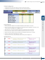
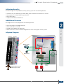
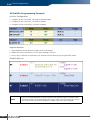
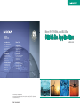
More IFs, THENs, and ELSEs Click&Go Application Moxa Inc. www.moxa.com [email protected] Moxa Americas Toll-free: 1-888-MOXA-USA (1-888-669-2872) Tel: +1-714-528-6777 Fax: +1-714-528-6778 www.moxa.com [email protected] Moxa China Shanghai Office Tel: +86-21-5258-9955 Fax: +86-21-5258-5505 www.moxa.com.cn [email protected] Moxa Europe Beijing Office Tel: +49-89-3 70 03 99-0 Fax: +49-89-3 70 03 99-99 www.moxa.com [email protected] Tel: +86-10-6872-3959/60/61 Fax: +86-10-6872-3958 www.moxa.com.cn [email protected] Moxa Asia-Pacific Shenzhen Office Tel: +886-2-8919-1230 Fax: +886-2-8919-1231 www.moxa.com [email protected] Tel: +86-755-8368-4084/94 Fax: +86-755-8368-4148 www.moxa.com.cn [email protected] ©2008 Moxa Inc. All rights reserved. The MOXA logo is a registered trademark of Moxa Inc. All other logos appearing in this document are the intellectual property of the respective company, product, or organization associated with the logo. PN: 1900020801090 Guidebook C lick&Go A pplication G uidebook Table of Contents ÔÔChapter 1: Overview of Click&Go Click&Go Features..................................................................................................................... 2 Products and Software Support................................................................................................. 3 Click&Go Version Differentiation................................................................................................ 3 Click&Go Configuration............................................................................................................. 4 THEN/ELSE Operation................................................................................................................. 4 Click&Go Rules 101................................................................................................................... 5 ÔÔChapter 2: Click&Go Applications Application 1 ioLogik E2260 Temperature Monitoring and Alarm Messaging for Laboratories Hospitals, and Blood Banks ................................................... 6 Application 2 ioLogik E2262 Temperature Monitoring, Alarms, and Shutdown Control for a Pumping System ................................................................... 9 Application 3 ioLogik E2210 An Alarm System for Walk-in Refrigerators in a Semiconductor Factory ................................................................................ 12 Application 4 ioLogik E2242 Control and Alarms for a Sump Pump System...................... 15 Application 5 ioLogik E2214 Reducing Downtime in a Runway Security System................ 18 Application 6 ioLogik E2212 Collecting Meter Readings for a Yacht Wharf Billing System ................................................................................ 21 Application 7 ioLogik E2210 Public Restroom Safety and Alarm System............................ 24 w w w. m o xa . co m e - m a i l : i n f o @ m o xa . co m 1 Overview of Click&Go Overview Everybody can do programming! Moxa’s Click&Go local control logic for the ioLogik Active Ethernet I/O server eliminates the cumbersome programming generally required for data acquisition, alarm messaging, and local control tasks. No knowledge of C-language or PLC ladder is required for field applications. Instead, users familiar with IF-THEN-ELSE statements will have no problem understanding the Click&Go interface and will be able to control I/O channels and alarm messaging after a few simple steps. The configuration utility also makes the control process easy to define and configure. Simply download the control logic to the ioLogik Active Ethernet I/O server and Click&Go will be ready-to-go in no time. ÔÔClick&Go Features • Twenty-four IF-THEN-ELSE Programming Rules Users do not need programming experience to use Click&Go. The easy and straightforward IF-THEN-ELSE programming style greatly simplifies the development and installation of I/O applications. With 24 IF-THEN-ELSE rules pre-installed and up to 3 IF conditions and 3 THEN/ELSE outputs or network actions per rule, Click&Go is suitable for most remote monitoring and alarm applications. • Local Monitoring and Local Control Click&Go can monitor the local I/O status for each input channel, trigger the status, or direct it to local output channels. • Remote Control One ioLogik can send control commands to, and receive responses from, another ioLogik, allowing you to set up an array of ioLogiks that work as a unit to accomplish control tasks. • Time-stamped Active Messaging All alarms, messages, e-mail notices, and TCP, UDP, and SNMP traps are time-stamped with the exact time of the events. • Peer-to-peer I/O Peer-to-peer I/O can be used to set up I/O mapping over Ethernet from the DI channel on one ioLogik to the DO channel on another ioLogik. 2 C lick&Go A pplication G uidebook ÔÔProducts and Software Support Although the current ioLogik E2000 series comes pre-installed with the original Click&Go V1 local control logic, the new Click&Go V2 offers more powerful functions to meet the needs of different applications. This Application Guide describes all the functions of Click&Go V2, which can be installed in the following products. Product Category Product Model Communication Interface Input/Output Firmware Version ioAdmin Version Active Ethernet I/O ioLogik E2210 Ethernet 12 DI, 8 DO V3.0↑ V3.0↑ ioLogik E2212 Ethernet 8 DI, 8 DO, 4 DIO V3.0↑ V3.0↑ ioLogik E2214 Ethernet 6 DI, 6 Relay V3.0↑ V3.0↑ ioLogik E2240 Ethernet 8 AI, 2 A0 V3.0↑ V3.1↑ Ethernet 4 AI, 12 DIO V3.0↑ V3.1↑ Ethernet 6 RTD, 4 DO V3.0↑ V3.1↑ ioLogik E2262 Ethernet 8 TC, 4 DO V3.0↑ V3.1↑ The easiest way to upgrade a current ioLogik without purchasing a new device is by installing the latest firmware and ioAdmin utility. There is no need to reconfigure earlier Click&Go rule-sets that are still running on your device. ÔÔClick&Go Version Differentiation Difference of Programming Method and Space Programming Method Programming Space Click&Go V1.x IF-THEN 16 Rules Click&Go V2.x IF-THEN-ELSE 24 Rules 1 Overview of Click&Go ioLogik E2242 ioLogik E2260 Function Support Click&Go V1.0 Click&Go V1.1 Click&Go V2.x Input Monitor and Output Control √ √ √ Counter Monitor and Reset √ √ √ Timer Trigger √ √ √ Delay Timer √ Timer √ Internal Register √ Remote Action √ Schedule √ SNMP Trap √ √ √ Active Message √ √ √ e-Mail √ √ √ √ CGI Command w w w. m o xa . co m e - m a i l : i n f o @ m o xa . co m 3 Overview of Click&Go ÔÔClick&Go Configuration After setting the IP address for the ioLogik Ethernet I/O server, Click&Go logic can be configured by following the procedure below. I/O Mode Configuration I/O Alias Name Configuration I/O Test Activate Rule-sets Define the Logic Define Global Variables Import/Export Configuration ÔÔTHEN/ELSE Operation Under the THEN column, you can specify up to 3 actions that will be performed when the conditions under the IF column are satisfied. You can also specify up to 3 actions that will be performed under the ELSE column when the IF column is NOT satisfied. Possible actions include changing the status of a DO channel, starting or stopping an Event Counter, or sending a message by SNMP trap, TCP, UDP, or e-mail. (Note: 1 = True, 0 = False) IF Conditions A1 A2 A3 Action 0 0 0 0 Triggers ELSE action 0 0 1 0 Triggers ELSE action 0 1 0 0 Triggers ELSE action 0 1 1 0 Triggers ELSE action 1 0 0 0 Triggers ELSE action 1 0 1 0 Triggers ELSE action 1 1 0 0 Triggers ELSE action 1 1 1 1 Triggers THEN action A3 Result of OR Logic Action IF Conditions A1 4 Result of AND Logic A2 0 0 0 0 Triggers ELSE action 0 0 1 1 Triggers THEN action 0 1 0 1 Triggers THEN action 0 1 1 1 Triggers THEN action 1 0 0 1 Triggers THEN action 1 0 1 1 Triggers THEN action 1 1 0 1 Triggers THEN action 1 1 1 1 Triggers THEN action C lick&Go A pplication G uidebook ÔÔClick&Go Rules 101 IF-THEN-ELSE The number one rule in Click&Go programming is “program the way you think.” Just remember that if the result of the IF logic is true, then the THEN actions will be triggered, but if the result of the IF logic is FALSE, then the ELSE actions will be triggered. IF “A” THEN “B”, ELSE “C” Where There is an ON Logic, There is an OFF Logic For each action triggered, users must specify the result for when the conditions have been met and when the conditions have not been met. For example, a simple alarm light application would require an IF statement to turn the alarm light ON and another IF statement to turn the alarm OFF. Sometimes the OFF logic can be performed by using the ELSE action. IF DI_0=ON THEN DO_0=ON IF DI_0=OFF THEN DO_0=OFF OR IF DI_0=ON THEN DO_0=ON, ELSE DO_0=OFF Rules Run in a Loop The complete list of 24 rules run in a loop. After the last rule, Click&Go will start over from the first rule. To avoid conflicts, it’s a good idea to check what happens when the cycle restarts at Rule #1. IF A Rule #1 IF B AND / OR IF C IF J Rule #2 IF K AND / OR IF L THEN D ELSE G THEN E ELSE H THEN F ELSE I THEN M ELSE P THEN N ELSE Q THEN O ELSE R Overview of Click&Go 1 Rule #24 w w w. m o xa . co m e - m a i l : i n f o @ m o xa . co m 5 Click&Go Application Application 1 ÔÔ ioLogik E2260 Temperature Monitoring and Alarm Messaging for Laboratories, Hospitals, and Blood Banks ÔÔProject Background Laboratories, hospitals, and blood banks refrigerate their stocks of biochemical medicines, organic complexes, solutions, and blood at temperatures between 2 to 8°C to preserve quality. Constant monitoring is required to prevent vaporization, chemical change, or contamination. Therefore, alarm messages must notify staff immediately if any drastic change in temperature occurs. ÔÔApplication Requirements The existing network uses Ethernet SNMP (Simple Network Management Protocol) to gather necessary information such as network traffic and line status. Most of the I/O signal monitoring, such as temperature monitoring, runs on Modbus/TCP or other proprietary protocols that take time for IT engineers to learn. As a result, a temperature monitoring system for the freezers must be established in a short amount of time and use SNMP protocol. ÔÔMoxa’s Solution The ioLogik E2260 Active Ethernet I/O server is designed for mixed I/O applications. The 6 RTD analog inputs are able to connect to 13 types of Pt (platinum) and Ni (nickel) sensors, in addition to 4 types of resistance measurement. The 4 embedded digital outputs are suitable for triggering a hard alarm locally. Most of all, the I/O status can be polled by the SNMP management software from the control center. The ioLogik also sends out SNMP traps to report the current status when the temperature becomes too high. ÔÔSolution Benefits The ioLogik E2260 provided the freezer temperature monitoring system with the following benefits: • I/O status control and monitoring via SNMP saves development effort • Automatic SNMP trap reports • A controller with both RTD inputs and digital output channels • 16-bit high resolution measurement with more than 13 types of sensor connection • Click&Go’s easy IF-THEN-ELSE style control logic, which eliminates the need for a PLC or RTU • Compact size and cost-effectiveness 6 C lick&Go A pplication G uidebook ÔÔAdditional Features The ioLogik E2260 is also equipped with the following features: • Local alarm output via digital channels • Alarm notifications via e-mail • Periodic status updates via SNMP trap • Moxa’s Active OPC Server to connect ioLogik devices to the most popular SCADA systems ÔÔSystem Diagram 2 ioLogik E2260 SNMP Trap Report Freezer Fridge#1 Temp. 4°C 11:30:52 Mon, 08/12/2008 RTD Sensor (RTD_1) Freezer RTD Sensor (RTD_2) Click&Go Application RTD Sensor (RTD_0) Central Monitor Freezer ÔÔClick&Go Programming Example I/O Alias and Mode Configuration 1. Configure the RTD_0 channel to PT100 mode, set the alias name of this channel to Freezer#1 2. Configure the RTD_1 channel to PT100 mode, set the alias name of this channel to Freezer#2 3. Configure the RTD_2 channel to PT100 mode, set the alias name of this channel to Freezer#3 w w w. m o xa . co m e - m a i l : i n f o @ m o xa . co m 7 Click&Go Application Program Behavior 1. Sends an SNMP trap to report the temperature of Freezer#1 when it reaches 8°C. 2. Sends an SNMP trap to report the temperature of Freezer#2 when it reaches 8°C. 3. Sends an SNMP trap to report the temperature of Freezer#3 when it reaches 8°C. Click&Go Rule-set 8 C lick&Go A pplication G uidebook Application 2 ÔÔ ioLogik E2262 Temperature Monitoring, Alarms, and Shutdown Control for a Pumping System ÔÔProject Background ÔÔApplication Requirements In order to keep the motors running smoothly and continuously, the tank farm requested a remote monitoring and control system to monitor the temperature of the motors. When the temperature rises too high, the front-end controller must shut down the motor and restart it after the temperature cools back down to an appropriate level. In addition, the front-end controller must send out a notification e-mail to the central site and field engineer’s blackberry when the motors shut down and recover. 2 Click&Go Application In the pumping system of a tank farm, bearings of a pump motor burn out after the motor runs non-stop for a period of time. The downtime and damage caused by overheated bearings raise maintenance costs and reduce output. Extra expenses are not only incurred from repairing or replacing the bearings, but paying the engineers for overtime as well. ÔÔMoxa’s Solution The ioLogik E2262 Active Ethernet I/O server is designed for mixed I/O applications. The 8 TC (thermocouple) inputs can connect 9 types of TC sensors (mV mode included) and the 4 built-in digital inputs can connect to multiple outputs such as alarms, buzzers, and lights. With the Click&Go local control logic, users can easily program the ioLogik E2262 to control the pumps, generate alarms, send status updates to the control center, or deliver e-mail notifications. Click&Go logic also allows the ioLogik to seamlessly integrate and manage temperature monitoring, output control, and alarms. ÔÔSolution Benefits The ioLogik E2262 provided the pumping system with the following benefits: • A controller with both TC temperature sensor inputs and digital output channels • 100 meters of TC sensor cable length with 2 built-in CJC • Click&Go’s easy IF-THEN-ELSE style control logic, which eliminates the need for a PLC or RTU • Alarm messaging can be generated via TCP, UDP, or SNMP trap, or e-mail • Compact size and cost-effectiveness w w w. m o xa . co m e - m a i l : i n f o @ m o xa . co m 9 Click&Go Application ÔÔAdditional Features The ioLogik E2262 is also equipped with the following additional features: • Scheduling feature sets start and shutdown times for the pump motors • Moxa’s Active OPC Server to connect ioLogik devices to the most popular SCADA systems ÔÔSystem Diagram Modbus/TCP E MA IL SNMP TC – K Type Temp. Input TC – K Type Temp. Input ioLogik E2262 Pump Motor - Auto Shutdown when overheated, Restart when normal Pump ÔÔClick&Go Programming Example I/O Alias Configuration 1. Temperature Input TC_0: 1st Pump Motor Temperature Sensor 2. Temperature Input TC_1: 2nd Pump Motor Temperature Sensor 3. Digital Output DO_0: 1st Pump Motor Start/Shutdown Control 4. Digital Output DO_1: 2nd Pump Motor Start/Shutdown Control 10 Pump C lick&Go A pplication G uidebook I/O Mode Configuration 1. Configure the TC channels to the correct Mode (K-type sensors with Celsius display in example below) and set the alias name for each channel 2. Configure the DO channel, set the alias name for each channel 2 1. 1st pump motor shuts down when temperature reaches a high of 110°C; alarm sent out by e-mail 2. 1st pump motor restarts when temperature reaches a low of 70°C; notification sent out by e-mail 3. 2nd pump motor shuts down when temperature reaches a high of 110°C; alarm sent out by e-mail 4. 2nd pump motor restarts when temperature reaches a low of 70°C; notification sent out by e-mail Click&Go Rule-set w w w. m o xa . co m e - m a i l : i n f o @ m o xa . co m Click&Go Application Program Behavior 11 Click&Go Application Application 3 ÔÔ ioLogik E2210 Alarm System for Walk-in Refrigerators in a Semiconductor Factory ÔÔProject Background A semiconductor factory preserves its stock of epoxy resin and silicon-based materials in large walk-in refrigerators at temperatures below 5°C. Temperatures higher than that will cause both the physical and chemical characteristics of the materials to change. This renders the materials unusable and lowers the factory’s productivity. It was found that increases in refrigerator temperature were due primarily to employees not closing the door tightly when entering and leaving the refrigerator. For this reason, the semiconductor factory requested an alarm system to notify maintenance personnel when the door was not closed tightly. ÔÔApplication Requirements The system requested needed to monitor the opening and closing of the walk-in refrigerator door. It takes a factory worker an average of 1 minute to enter the refrigerator, locate the appropriate materials, and exit the refrigerator with the materials in hand. This means that an alarm should only be generated when the door remains open for more than 1 minute. Due to the tight timeframe available for deploying the alarm system, engineers needed to find a quick solution that did not require extensive programming or complicated communication protocols. In addition to local control capabilities for the door sensor and alarm, the semiconductor factory also required a solution that would allow complete connectivity with a central PC or ERP/MES system. ÔÔMoxa’s Solution The ioLogik E2210 Active Ethernet I/O server is designed to handle a combination of I/O signals. The 12 digital inputs can connect to different door sensors and switches and the 8 built-in digital outputs provide flexible connections to multiple alarm devices. Unlike programming a front-end PC or stand-alone PLC, the ioLogik’s Click&Go control logic uses an easy to use IF-THEN-ELSE style of programming that doesn’t require any compilers or debugging tools. The ioAdmin utility also allows users to configure the alarm system within 5 minutes with the click of a button. Moreover, the ioLogik E2210 provides both Ethernet connectivity and several ways to update status, including e-mail warnings, TCP/UDP active messaging, SCADA/OPC connectivity, and SNMP trap I/O reports. 12 C lick&Go A pplication G uidebook ÔÔSolution Benefits The ioLogik E2210 provided the semiconductor factory with the following benefits: • A controller equipped with both digital inputs and digital output channels • Click&Go’s easy IF-THEN-ELSE style of control logic, which eliminates the need for a PLC or RTU • Alarm messaging via TCP/UDP/SNMP trap or e-mail • Compact size and cost-effectiveness ÔÔAdditional Features The ioLogik E2210 is also equipped with the following features: • More local input functions such as local acknowledgement or open detection of the control box • Moxa’s Active OPC Server to connect ioLogik devices to the most popular SCADA systems Active Message Fridge#1 Door Open, Alarm Trigger at 11:30:52 Mon, 08/12/2008 Ethernet Central Monitor Door Sensor (Digital Input DI_0) Click&Go Application ÔÔSystem Diagram 2 ioLogik E2210 Alarm Light (Digital Output D0_0) Alarm Siren (Digital Output D0_1) Refrigerator Door w w w. m o xa . co m e - m a i l : i n f o @ m o xa . co m 13 Click&Go Application ÔÔClick&Go Programming Example I/O Alias and Timer Configuration 1. Digital Input DI_0: Door-Sensor#1 2. Digital Output DO_0: Alarm#1 3. Configure the default interval of Timer_0 to 60 seconds Program Behavior 1. When the door is open, start the timer 2. When the timer times out after 60 seconds, trigger the alarm and send out an active message 3. Once the door is closed, disable the alarm and stop the timer Click&Go Rule-set 14 C lick&Go A pplication G uidebook Application 4 ÔÔ ioLogik E2242 Control and Alarms for a Sump Pump System ÔÔProject Background ÔÔApplication Requirements A better method of sump pump control is to use a closed-loop central monitoring system such as a SCADA system. In this case, a sensor is connected to a controller to turn the pump on and off automatically. The sensor and control mechanism should be able to detect the liquid level and start or stop the pumping action when the float switch senses that the liquid level is too high or too low. Multiple pump control and alarm generation must also be included as part of the control system. Alarm indicators should be triggered when the pump starts or when the water reaches a high level. Moreover, the sump pump must be controlled either automatically or manually from a remote location. 2 Click&Go Application Many industries use a sump pit to collect wastewater from machines, cutting oil, and toxic solutions from the production line. When the level of the liquid in the sump pit reaches a certain level, the liquid in the sump pit must be pumped out to a holding tank. If the system is set up as an open-loop system, engineers must periodically check the level of the sump pit. They must manually turn the pump on when the sump pit is nearly full, and then turn the pump off when the sump pit is nearly empty. ÔÔMoxa’s Solution The ioLogik E2242 is an Active Ethernet I/O server designed for mixed I/O applications. The 4 analog inputs are able to connect to liquid level sensors based on either voltage or electric current, and the 12 built-in configurable DIOs provide the best flexibility for connecting to multiple input switches or triggering pumps and alarms. With the user-friendly Click&Go local control logic, users can easily program the ioLogik E2242 to act as a front-end pump controller and alarm generator to automatically control the action of the pumps, generate alarms, and send the most up-to-date status to the central SCADA system, or by e-mail to the field engineers. ÔÔSolution Benefits Moxa’s ioLogik E2242 provided the sump pump control system with the following benefits: • Click&Go’s easy IF-THEN-ELSE style control logic, which eliminates the need for a PLC or RTU • Active reports via TCP/UDP/SNMP trap, and e-mail • Compact size and cost-effectiveness w w w. m o xa . co m e - m a i l : i n f o @ m o xa . co m 15 Click&Go Application ÔÔAdditional Features The ioLogik E2242 is also equipped with the following features: • Scheduling function to set when to pump the wastewater • Moxa’s Active OPC Server to connect ioLogik devices to the most popular SCADA systems ÔÔSystem Diagram Primary Sump Pump Control Cabinet SCADA Backup Sump Pump Ethernet ioLogik E2242 Level Sensor (Analog Input AI_0) Holding Tank High-High Alarm Indicator (Digital Output DO_0) High-High Level – Backup Pump ON Primary Pump Control (Digital Output DO_1) High Level – Primary Pump ON Primary Pump Indicator (Digital Output DO_2) Backup Pump Control (Digital Output DO_3) Backup Pump Indicator (Digital Output DO_4) ÔÔClick&Go Programming Example I/O Alias Configuration 1. Analog Input AI_0: Level Sensors 2. Digital Output DO_0: High-high Alarm 3. Digital Output DO_1: Primary Pump Control 4. Digital Output DO_2: Primary Pump Indicator 5. Digital Output DO_3: Backup Pump Control 6. Digital Output DO_4: Backup Pump Indicator 7. Internal Register_0: Remote Primary Pump Control 8. Internal Register_1: Remote Backup Pump Control 16 Low Level – Both Pumps Off Sump C lick&Go A pplication G uidebook I/O Mode Configuration 1. Configure the DIO channel to DO mode, set the alias name for each channel 2. Configure the AI channel to 4-20 mA mode, set the alias name for each channel 2 1. Primary Pump and its indicator are activated when liquid level reaches High (15 mA input) 2. Backup Pump and its indicator are activated when the liquid level reaches High-high (18 mA input), in case Primary Pump fails. High-high Alarm is triggered as well. 3. High-high Alarm is OFF when the liquid level goes back to High, both pumps keep working 4. Primary Pump and its indicator are de-activated when liquid level reaches Low (7 mA input) Click&Go Application Program Behavior 5. Backup Pump and its indicator are de-activated when the liquid level reaches Low (7 mA input) 6. Send e-mail warnings when High-high level is reached 7. Remote control the Primary Pump and Backup Pump manually (Internal Register 0/1) Click&Go Rule-set w w w. m o xa . co m e - m a i l : i n f o @ m o xa . co m 17 Click&Go Application Application 5 ÔÔ ioLogik E2214 Reducing Downtime in a Runway Security System ÔÔProject Background Relay control for lighting and motion detection is at the heart of a runway perimeter intrusion detection and alarm system application. On a typical day, aircraft constantly come and go on both the runway and adjacent taxiways, creating a dangerous environment for anyone or anything entering the runway. For this reason, installing a stand-alone, remote control system for intrusion detection and issuing alarms is an absolute necessity for avoiding accidents. ÔÔApplication Requirements Besides motion sensors, alarm lights, and a second-tier (external) relay board, a remote controller is the most important component inside the device cabinet. Programming power on the controller should be available to perform the local control. At the same time, the relay components on a second-tier relay board should be replaced in advance to avoid failures when they wear out. On average, the relays can be used 25,000 times, but should be replaced after being used 10,000 times to avoid unexpected failures. The local controller not only controls the on/off functions of the alarm lights when the sensors are activated, but is also required to send a warning when the usage of a specific channel of the second-tier relay board reaches 10,000 times. ÔÔMoxa’s Solution The ioLogik E2214 is designed with 6 DI and 6 relay channels. With the user-friendly Click&Go local control logic, users can easily program the ioLogik E2214 as the front-end relay controller to detect intrusions. Click&Go also supports a special function called ‘’relay counter storage’’ to provide readings of the current relay usage. This allows the ioLogik E2214 to send out TCP packets to the central SCADA system and a warning e-mail at the same time so that site maintainers can replace the relay components of the second-tier relay board. After the replacement, site maintainers simply press the RESET button attached to the ioLogik E2214 to clear the counts. In other words, there is no need to use laptop computers or remote commands. 18 C lick&Go A pplication G uidebook ÔÔSolution Benefits The Moxa ioLogik E2214 provided the runway security system with the following benefits: • Click&Go’s easy IF-THEN-ELSE style control logic, which eliminates the need for a PLC or RTU • Active reports via TCP/UDP/SNMP trap and e-mail • Relay count reports • Compact size and cost-effectiveness ÔÔAdditional Features 2 The ioLogik E2214 is also equipped with the following features: Click&Go Application • Local alarm output using digital channels • Alarm notifications via e-mail • Periodic status updates with SNMP trap • Moxa’s Active OPC Server to connect ioLogik devices to the most popular SCADA systems ÔÔSystem Diagram Runway Taxiway Ethernet 24 VDC 6 Motion Sensors Digital Input ioLogik E2214 Relay_0 Output RESET button 00964 Relay_1 Output 06490 230 VAC 2nd-tier Relay Boards 27 Manual Switch Runway Edge Detection & Alarm Light Control w w w. m o xa . co m e - m a i l : i n f o @ m o xa . co m 19 Click&Go Application ÔÔClick&Go Programming Example I/O Alias Configuration 1. Configure the alias name of DI_0 channel to MotionSensor#0 2. Configure the alias name of DI_1 channel to RESET#0 3. Configure the alias name of DO_0 channel to Light#0 Program Behavior 1. Lights should be turned ON locally (motion sensor) and remotely 2. Reports the current relay counts via e-mail upon reaching 1,000 uses 3. After a relay is replaced, site maintainers can manually reset the counts by pressing the RESET button Click&Go Rule-set NOTE 20 In this case, internal Register-0 is used to control the relay output to a light. The control is done outside the ioLogik or locally depending on the DI status when running Click&Go logic. Refer to the Click&Go user’s manual for the Modbus/TCP Address table of the internal registers. C lick&Go A pplication G uidebook Application 6 ÔÔ ioLogik E2212 Collecting Meter Readings for a Yacht Wharf Billing System ÔÔProject Background ÔÔApplication Requirements The original system in place required patrons to manually check the electricity readings at the charge station and return to the hotel for check out. This system worked fine when the weather was good and patrons did not need to travel very far between their yacht and the hotel. However, when the conditions were bad, there were complaints. In addition, protecting against electricity thieves was also quite difficult. To address these issues, the hotel decided to integrate remote control and data acquisition into the billing system. 2 Click&Go Application Patrons generally require refueling and battery charging as basic services after docking their yachts at a hotel’s wharf. Upon disembarking, customers simply connect their yachts to the charge station and check in at the front desk. The hotel wanted a system to remotely start the charge station after customers check in and stop the charge station after they check out. More importantly, the hotel wanted to integrate the charge station meter readings with an electronic billing system. ÔÔMoxa’s Solution The ioLogik E2212 Active Ethernet I/O server is designed for mixed I/O applications. The 8 digital inputs and 4 configurable DIOs provide just what’s needed to connect to the power switches and electricity meters. With the world’s easiest to program local control logic, Click&Go, users can easily program the ioLogik E2212 as a frontend controller in a short time, control and record the electricity supply, and send readings as ASCII text messages that can be easily integrated into the billing system. ÔÔSolution Benefits The ioLogik E2212 provided the yacht wharf billing system with the following benefits: • A controller equipped with both digital inputs and digital output channels • Easy IF-THEN-ELSE style Click&Go control logic, which eliminates programming and debugging effort, and replaces the PLC or RTU • Backup storage for meter readings when the ioLogik’s power goes down • Alarm messaging via TCP/UDP/SNMP trap or e-mail • Compact size and cost-effectiveness w w w. m o xa . co m e - m a i l : i n f o @ m o xa . co m 21 Click&Go Application �Additional Features The ioLogik E2212 is also equipped with the following features: • Battery status detection to prevent over-charging the battery • Moxa’s Active OPC Server to connect ioLogik devices to any of the most popular SCADA systems ÔÔSystem Diagram Ethernet Active Message Event Counter#1 Current Counts: 115 11:30:52 Mon, 08/12/2008 Central Monitor ioLogik E2212 Power Switch (Digital Output D0_0) Electric Meter (Event Counter_0) ÔÔClick&Go Programming Example I/O Alias and Mode Configuration 1. Configure the 1st input channel to Event Counter mode, and Power On Settings to START. Configure the alias to Meter#1. 2. Configure the 1st digital output’s alias to PWR_Switch#1 22 C lick&Go A pplication G uidebook Program Behavior 1. Turns on the power switch remotely and start recording the counts. 2. Turns off the power switch remotely and stop recording the counts. Report the readings and reset the counter. Click&Go Rule-set 2 Click&Go Application NOTE In this case, internal Register-0 is used to control the power switch attached to the digital output channel. The control is done outside the ioLogik when running Click&Go logic. Refer to the Click&Go user’s manual for the Modbus/TCP Address table of the internal registers. w w w. m o xa . co m e - m a i l : i n f o @ m o xa . co m 23 Click&Go Application Application 7 ÔÔ ioLogik E2210 Public Restroom Safety and Alarm System ÔÔProject Background Security and safety systems in public facilities such as train stations, museums, and movie theaters, are increasingly incorporating medical assistance, police, and fire alarms for patrons to trigger in emergency situations. In particular, public restrooms are deploying emergency alarm systems to assist women, handicapped patrons, and parents with children. ÔÔApplication Requirements Several types of emergency push buttons are required for this application. In the women’s restroom, an individual emergency push button is needed in each stall and on the wall near the entrance. Handicap stalls include two types of buttons. One type of button calls for medical assistance and is located near the flush handle under a plastic covering. In case the patron falls down while moving between the toilet and his wheelchair, suffers a heart attack, or is unable to get back up for any other reason, there is another emergency button located near the floor to provide better assistance. In most cases, it is attached to the other call button with a 2-meter expansion cable. The emergency button located near the door is designed primarily to allow people walking by to report a fire alarm or accident. After an emergency button is triggered, alarm lights will start flashing and the speaker will broadcast for 30 to 60 seconds. The event will be reported to the control center as well. After receiving the alarm, the control center can remotely turn off the alarm light outside the restroom. Finally, security personnel or paramedics will arrive. ÔÔMoxa’s Solution The ioLogik E2210 Active Ethernet I/O server is designed for mixed I/O applications. The 12 digital inputs can connect to various kinds of sensors and switches and the 8 built-in digital outputs provide the best flexibility in connecting to multiple alarm devices. With the world’s easiest local control logic, Click&Go, users can easily program the ioLogik E2210 as a front-end alarm controller to automatically response actions, such alarm lights and speakers, when the emergency buttons are pushed. 24 C lick&Go A pplication G uidebook ÔÔSolution Benefits The ioLogik E2210 provides the restroom alarm system with the following benefits: • A controller equipped with both digital input and digital output channels • More local input functions such as local acknowledgement and open detection of the control box • Click&Go’s easy IF-THEN-ELSE style control logic, which eliminates the need for a PLC or RTU • Simultaneous control for local and remote Ethernet • Alarm messaging can be generated via TCP, UDP, or SNMP trap, or e-mail • Compact size and cost-effectiveness 2 ÔÔAdditional Features The ioLogik E2210 is also equipped with the following features: ÔÔSystem Diagram Control Box Ethernet Alarm Light (Digital Output DO_0) Alarm Speaker (Digital Output DO_1) Emergency Emergency Button (Digital Input DI_0) ioLogik E2210_Site (192.168.19.101) Emergency Button (Digital Input DI_1) Emergency Click&Go Application • CGI Command to integrate video surveillance to record or take snapshots during an emergency • Powerful IF-THEN-ELSE programming with 24 rule spaces • Moxa’s Active OPC server to connect Logik devices to the most popular SCADA systems Emergency Button (Digital Input DI_2) Site #001 e-mail Notice Ethernet Site #001 Alarm Light (Digital Output DO_0) Alarm Speaker (Digital Output DO_1) Patrol Site #001 Ack. Button (Digital Input DI_0) ioLogik E2210_Central (192.168.19.1) Central Office w w w. m o xa . co m e - m a i l : i n f o @ m o xa . co m 25 Click&Go Application ÔÔClick&Go Programming for Example_Site I/O Alias and Timer Configuration for ioLogik_Site 1. Digital Input DI_0: Higher Emergency Button 2. Digital Input DI_1: Lower Emergency Button 3. Digital Input DI_2: Front-end Emergency Button 4. Digital Output DO_0: Alarm Light 5. Digital Output DO_1: Alarm Speaker 6. In the Click&Go Manual configure the Timer to 60 seconds Program Behavior for ioLogik E2210_Site 1. Regardless of which emergency is triggered, turn on the local alarm light and speaker 2. Regardless of which emergency is triggered, send out e-mail notice to central administrator and the patrol 3. Regardless of which emergency is triggered, turn on the central Alarm Light for this specific site. 4. Regardless of which emergency is triggered, turn on the central alarm Speaker (there is only one central speaker) 5. After 60 seconds, turn off the local Alarm Speaker 6. When receiving an acknowledgement from central, turn off the local Alarm Light 26 C lick&Go A pplication G uidebook Click&Go Rule-set for ioLogik E2210_Site 2 Click&Go Application Logic #1 - Sending Remote Action to ioLogik E2210_Central NOTE This Remote Action ID is configured to trigger the both remote (central) Alarm Light and Speaker. w w w. m o xa . co m e - m a i l : i n f o @ m o xa . co m 27 Click&Go Application Remote Action IP and ID mapping is shown below: IP #1 + ID #1 IP #1 + ID #2 ioLogik E2210_Site #001 IP #2 + ID #1 IP #2 + ID #2 Four Remote Actions are Processed IP #1 + ID #1 IP #1 + ID #2 IP #2 + ID #1 IP #2 + ID #2 ioLogik E2210_Central #002 ioLogik E2210_Site #002 Logic #3 - Receiving Remote Action from ioLogik E2210_Central NOTE 28 Receiving this Remote Action will disable the local (site) Alarm Light C lick&Go A pplication G uidebook ÔÔClick&Go Programming for Example_Central I/O Alias and Timer Configuration for ioLogik_Central 1. Digital Input DI_0: Site #001 Ack, Button 2. Digital Output DO_0: Site #001 Alarm Light 2 1. Turns on the specific Alarm Light when an alarm from that site is activated 2. Turns on the Alarm Speaker when an alarm from any site is activated 3. An Acknowledge Button is used to disable the local (central) alarm light, local Alarm Speaker, and the remote (site) Alarm Light. Click&Go Rule-set for ioLogik E2210_Central w w w. m o xa . co m e - m a i l : i n f o @ m o xa . co m Click&Go Application Program Behavior for ioLogik E2210_Central 29 Click&Go Application Logic #0 - Receiving Remote Action from ioLogik E2210_Site NOTE This Remote Action disables the remote (site) Alarm Light Logic #2 – Sending Remote Action from ioLogik E2210_Site NOTE 30 This Remote Action disables the remote (site) Alarm Light