1
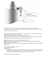
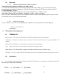
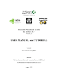
BIT User Manual About this manual WARNING Know your BIT System Components Operation Methods Maintenance, charging 3.3.1. Cleaning General handling Software Setup Calibrating the BIT Inclinometer calibration Calibration procedure: Gyro calibration Calibration procedure: Depth meter calibration Calibration procedure: Options 5. Operating the BIT Method A: Testing the verticality of open boreholes Welding the mounting plate Method B: Testing existing piles using access tubes Reporting Transferring data from Android to the PC Producing a report Report customization Theoretical background TERMINOLOGY Calculations Troubleshooting Getting support Appendixes Technical Specifications Capabilities and limitations 1. About this manual 1.1. WARNING Although BIT itself contains no dangerous components, working on construction sites in general and close to rigs, cranes and open boreholes in particular might be a dangerous activity. You should participate in safety training Always obey local safety rules. 2. Know your BIT 2.1. System Components 1. BIT Main Unit inside cable reel The Main Unit is mounted inside a splashproof cable reel, with 100 m cable as a standard other lengths are available as a special order. The Main Unit electronics include a rechargeable Liion battery with a builtin charger, signalconditioning circuitry, a 2.4 MHz wireless transceiver to communicate with the depth meter and a Bluetooth module that communicates with the computer. 2. BIT sensor (Shown here with a mounting plate) The sensor contains a precision biaxial inclinometer that measures the inclination and a solidstate gyro that keeps track of the sensor's bearing when the bucket is rotated. The BIT sensor electronics are e nclosed in rugged, waterproof, stainless steel cylinder with a 25 mm OD. 3. Wireless Depth meter The splashproof depth meter is equipped with a magnetic encoder, accurate to 10 mm and a wireless module that transmits the depth readings to the Main Unit. 4. Android phone/tablet (not provided) 5. Power adapter for BIT 6. Power adapter for Depth Meter 6. Disposable mounting plate 7. Tube adapter (Optional, for testing in tubes) The standard tube adapter fits inside access tubes 45 to 67 mm inside diameter. Other sizes are available as special order. 2.2. Operation Methods BIT has two operation methods: ● Method A test the inclination of open boreholes, either dry or wet, before reinforcement is inserted and the concrete poured. ● Method B test the inclination of existing piles of all kinds, using access tubes Method A The BIT sensor is mounted on the drilling bucket or grab that is used as a centralizer. The sensor is lowered to the bottom in predetermined stages. At each stop, once the computer indicates that stable readings had been achieved, both inclination and bearing are read and saved. The BIT calculates the deviation by integrating the inclination over the depth traveled and correcting for bearing. The procedure is repeated on the return to the surface, and the closing error calculated. If the error is within acceptable boundaries, it is distributed over the whole depth. The test results are plotted in either side view or top view. Method B The BIT is operated as in Method A, but instead of being mounted on the drilling bucket or grab it is mounted on top of the tube adapter. 2.3. Maintenance, charging 3.3.1. Cleaning After use clean the BIT components with clean water. Note that the BIT sensor is waterproof only when mounted on the cable with the special waterproof connector. If the tube adapter is used it should be thoroughly cleaned under the tap with a hard brush and let dry. After drying the wheels should be checked for free running and the bushings oiled lightly. 3.3.2. Charging The BIT comes with two power adapters: 1. A 12V nominal power adapter for charging the Main Unit from a 120240 VAC wall socket. 2. A 5V nominal power adapter for charging the Depth Meter from a USB outlet or a cellphone charger, this power adapter attaches to the respective device by suitable magnetic connectors. The magnetic polarity and different pole spacing prevent connecting the wrong adapter or the wrong polarity. When an adapter is attached to a device an orange LED lights up until the device is fully charged. General handling 2.4. Software Setup BIT is installed on any Android phone or tablet with Bluetooth support Minimal Android version supported: 2.2.x Recommended Android version: as high as possible, 4.2 and higher Avoid using Versions 4.0.1 to 4.0.4 (Ice Cream Sandwich) due to general Bluetooth problem with this version which Google fixed in later versions. To install BIT, visit Google Play market and search for “Piletest” here is a direct link https://play.google.com/store/apps/details?id=piletest.bit 3. Calibrating the BIT The BIT should be calibrated: ● Before the first use ● When replacing a smartphone/tablet (The calibration values are stored in the phone/tablet) ● After uninstalling/reinstalling ● Periodically see below There are three items to be calibrated: 3.1.1. Inclinometer calibration Background: The BIT sensor has small internal inclination offsets in the X and Y directions. The calibration process measures and compensates for these offsets. Inclinometer calibration should be repeated daily, before testing. Calibration procedure: The calibration is done by taking two readings, 180° apart. For brevity the software refers to those readings as “South” and “North” but the true magnetic orientation is irrelevant. The surface on which the calibration is done does not have to be perfectly horizontal, but must be 1) stable and 2) smooth. BIT is supplied with an Aluminum base and plate which are used just for calibration. ● Select ⋮MenuInclinometer Calibration ● Place the sensor upright, pointing “South” and select [OK] ● Once the reading has 100% stabilized , turn the sensor to “North” and press [OK] again. ● Once the “North” reading has stabilized, observe the results and press [Save] For verification, place the sensor on a perfectly horizontal surface, select ⋮MenuSelf Test and observe the East and North readings which should be close to zero. 3.1.2. Gyro calibration Background: The BIT Gyro has an internal drift a nearly linear change over time. The gyro calibration process measures this drift and compensates for it. Gyro calibration should be repeated daily, before testing. Calibration procedure: ● Select ⋮MenuGyro calibration ● Place the sensor on a stable, horizontal surface, in a vertical position ● Press [Reset] ● Wait 2 minutes without touching the sensor, or until you get at least 99.5% stabilization, and press [Save] For verification, select ⋮MenuSelf Test and observe the “Azimuth” readings. The readings should stay stable with no more than 5 degrees per minute 3.1.3. Depth meter calibration Background: The depth wheel is counting exactly 100 readings per wheel turn. The depth calibration sets up the relation between those readings and the length of cable fed or pulled over the wheel. Depth calibration must be repeated for verification every 6 months. The depth wheel is digital and no change in performance is expected over time. Calibration procedure: Pass the BIT sensor through the wheel. NOTE : Always pass the sensor from left to right, or you will get negative readings. Using an adhesive tape or waterproof pen, mark two lines on the cable, 10m apart (Exactly) Suggestion: you may use the "Piletest.com" markings on the cable that are printed at 1m separation. Note: You may do the calibration on a shorter or longer distance, however 5m is a minimal distance for acceptable accuracy Calibration can be done off the borehole or even in the office, provided the cable is kept in good contact with the wheel.. ● Select ⋮ MenuDepth Calibration ● Using the [+] and [] buttons, set the actual length to 10m according the the spacing you have marked ● Pull the cable so that the lower mark (The one closer to the sensor) is aligned with the wheel or any stable reference point ● Press [Reset] ● Lower the cable while in tight contact with the wheel until the top mark is aligned with your reference point ● Press [Save] repeat the process for verification, this time the “Calculated length” and “Actual length” must match +/ 10 mm. Options Select ⋮MenuOptions (Incomplete ) 5. Operating the BIT 3.2. Method A: Testing the verticality of open boreholes CAUTION : Some rigs have an embedded monitoring computer that must be disconnected when welding or the high welding current may damage it Welding the mounting plate For accurate results, The BIT should be installed with its axis precisely parallel to the axis of the bucket. Improper installation might create inaccurate results. Please follow those instructions carefully! Wherever possible, for a centralizer use only a cylindrical coring bucket that hangs exactly vertically from the kelly bar. Avoid using a bucket which has a side door or trap mechanism. If the bucket does not hang vertically, place it vertically on the ground besides the borehole. With the bucket in vertical position, weld the mounting plate to the top of the bucket on a suitable clean, flat, horizontal surface. 1. Place the plate as accurately as possible and spotweld it on one point. 2. DoubleCheck the horizontality on X and Y axis at this stage you can still finetune the plate horizontality using a hammer. 3. Perform final welding on at least three points. The plate surface must be exactly perpendicular to the bucket sidewall as shown in the image below: If repeated testing with the same rig and bucket/auger is expected, the plate may be welded permanently, otherwise just spotweld it on at least three points so that it can later be removed using a hammer and chisel or a disc grinder. Hang the depth meter from any convenient spot on the rig above the hole. Pull the BIT sensor through the depth meter (note the direction, left to right). Testing is started when the sensor arrow is pointing to the site North. Make sure the mounting place is clean from mud or debris. Wash if needed. always use the provided plastic plug to protect the plate’s thread. In case it is lost, use a wine cork. Tightly screw the sensor into the mounting plate, aligned to North. NOTE 1 : Do not use any tools on the sensor’s body. Turn it with a steel bar inserted into the hole provided at the bottom of the sensor. NOTE 2 : The definition of “North” can be magnetic, geographic, or any sitespecific direction designated and agreed on. Turn on the BIT if not already connected Open or create a new folder Click [New test] Some rigs have several telescopic parts that lock into each other by a small rotation. In this case mark the [Use Gyro] checkbox. In all other cases where you are sure that the rig bucket remains pointing to the north and does not rotate it is better to keep this unchecked. Bring the BIT sensor to the starting position: 1. Sensor arrow pointing to North 2. At depth = 0.0m Press [OK] to see the logging screen. In his screen the whole logging is performed automatically, no need to click any button until the rig is back at the surface (depth 0). Follow the instructions and stop when required. Keep some tension on the cable at all times. (Test intervals can be set under [Tools][Options] – even during testing) If you have reached the bottom of the borehole at a depth in between intervals and the software does not take a reading, press [Read!] to force it take a reading at that point. (For example, if the software it set to take readings every 5 meters, the last reading was at 40m and the bottom of the borehole is at 42m, the software must be instructed to take a reading at this depth) After reaching the bottom raise the rig, stopping at the same levels. CAUTION : Keep the cable tight in order to prevent it from being tangled with the auger/bucket and to assure depth accuracy. When you have returned to the surface, the indication will be “ Completed ”, press [Done] In case you have used a gyro, Make sure the sensor is pointing to the North and press [Next] to calculate the gyro drift. At this stage you may see the test results on the screen or may switch from side view to top view and show/hide the test results. The red zone, showing the permitted inclination can be set in [Tools][Options] When you are done observing the results, click [Next] Provide information about the borehole (at least Name/ID) and press [Save] Files are being saved under “My documents\BIT projects” The file can be saved into a folder. It is recommended that files from the same project will be grouped together. Click [Next] when done to return to the main page 3.3. Method B: Testing existing piles using access tubes The BIT can be used to test bored piles and diaphragm walls with preinstalled access tubes (the same used for cross hole ultrasonic testing). In addition it can be used on precast and prestressed driven piles with a central hole intended for jetting. The verticality of H piles and sheet piles can also be tested if they are equipped with suitable steel access tubes welded to them. The procedure follows the same one of Method A, if the bucket centralizer is replaced with the optional tube adapter. 3.4. Reporting 3.4.1. Transferring data from Android to the PC There are two main options for transferring the data to the PC A Connect the Android device to the PC using a data transfer cable (USB) If your device has this option, select data device instead of media device. Use the PC explorer to drag the BIT files to a folder on your PC B Recommended Dropbox You must first install Dropbox on both your PC and your Android device. Dropbox is free. Select ⋮MenuOptions and check [Dropbox integration]. Confirm and you are done. Now every file is automatically copied to your Dropbox folder and will be automatically copied to your PC once your Android device is connected to the Internet. 3.4.2. Producing a report Once the data is on your PC, run the “BITReporter” application, select the BIT files and click [Report] Report customization (Incomplete ) 4. Theoretical background 4.1. TERMINOLOGY Borehole axis – The trajectory the Kelly bar tip follows when lowered into the borehole. Inclination – the angle, in either degrees or percent, between the borehole axis at any given depth to the vertical. Battered pile or raking pile – a pile purposely constructed at an inclination. Stop – a depth in the hole at which stabilized inclination readings are taken. Depth interval – the mean distance along the borehole axis between two consecutive stops. Deviation – the vector, measured in the horizontal plane, from the planned borehole axis to the asmade one. 4.2. Calculations a. For each stop numbered [n], the inclinations in the XY directions are transformed to inclinations in the NE directions by the following relationships. (1) (2) b. For each stop numbered [n] at depth = D , the deviations of the pile axis in the NE directions are calculated n as follows. (3) (4) (5) (6) Inclination and deviation explained And the combined deviation expressed as a polar vector is: (7) where (8) (9) c. Ideally, for the final surface reading N, the total calculated deviation r N should be zero. d. If the closure error r N is less than a predetermined threshold value (expressed as a fraction of pile length), it is proportionately distributed among all stops. e. If the closure error rN exceeds the threshold value the operator receives a warning and may decide to repeat the test. f. For each stop, the corrected downward and upward deviations are averaged and transformed to polar coordinates. 5. Troubleshooting (Incomplete ) 5.1. Getting support Please contact [email protected] 6. Appendixes 6.1. Technical Specifications Physical Housing Shipping weight Temperature range Humidity Power Sensor : Rugged stainless steel case Instrument: Inside Schill cable reel 12Kg 10 ~ 50 °C 90% (noncondensing) Internal Liion rechargeable battery, 7.4 V 500mAh, sufficient for a full day’s work AC adapter/charger included Technical Wireless Depth meter Bluetooth, 2.4Ghz Inclinometer Gyro Cables Wireless (Zigbee) with internal 1400mAh battery and magnetic charger adapter MEMS, dual axis, temperaturecompensated MEMS, Automatic drift compensation 100m (150m optional) rugged Polyurethane jacket Performance Borehole depth Borehole diameter Productivity Accuracy 5m140m Unlimited 1020 minutes / borehole (Typical) Better than 0.1% (0.07°) Output Reporting Produced on office PC, including top view of pile axis, vertical section in the direction of maximum inclination and more Requirements Minimum computer Android smartphone/tablet with Bluetooth hardware 6.2. Capabilities and limitations (Incomplete)