1
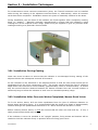
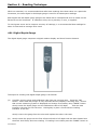
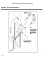
Mechanical Triaxial Jointmeter
With Digital Or Dial Depth Gauge
User Manual
Man 066
2.0.2
04/07/2014
Chris Spalton
Andy Small
Chris
Rasmussen
Manual No.
Revision
Date
Originator
Checked
Authorised for
Issue
User Manual
1
Contents
Section 1 :
Introduction ................................................................................................................................. 3
Section 2 :
General Information ................................................................................................................. 4
Section 3 :
Installation Techniques ........................................................................................................... 5
3.01
3.02
Section 4 :
4.01
4.02
Section 5 :
5.01
5.02
5.03
5.04
5.05
Appendix A.
User Manual
Installation During Casting .......................................................................................................... 5
Installation After Concrete Works Completed/Across Rock Joints ...................................... 5
Reading Technique .................................................................................................................... 7
Digital Depth Gauge...................................................................................................................... 7
Dial Depth Gauge .......................................................................................................................... 8
Digital Depth Gauge - Technical Data .............................................................................. 10
Button Functions .......................................................................................................................... 10
Technical Specification ............................................................................................................... 10
Mains Supply & Charging ........................................................................................................... 10
Charging ........................................................................................................................................ 11
Mains Operation ........................................................................................................................... 11
Figure 1 General Dimensions ............................................................................................ 12
2
Section 1 : Introduction
This instruction manual describes the techniques required for the installation and reading of the
Triaxial Jointmeter for use with digital or dial depth gauge.
It is important that the equipment covered by this manual should be installed and operated by
competent and suitably qualified personnel.
The techniques described are intended to serve as a general guide and will vary to suit
particular site conditions.
User Manual
3
Section 2 : General Information
The Triaxial Jointmeter, as its name implies, is designed to measure movement in three axes
across any joint, be it a construction joint in concrete or a tension crack in rock. With reference
to Figure1, stainless steel bushes orientated in three directions, horizontal, vertical and lateral
with respect to the concrete or rock surface, accept either a digital or dial depth gauge, which
precisely measures the distance to corresponding stainless steel anvils. Comparison of readings
with base data indicates the direction and magnitude of movement.
Each Jointmeter comprises two parts, each a hot zinc-coated mild steel arm with a coated
reinforcement bar anchor stem. One arm incorporates the bushes, the other the anvils.
The Triaxial Jointmeter is reliable, accurate and relatively simple to install and read. It can be
used to monitor movement across most joints, with the qualification that for increasingly acute
internal angles (i.e: less than 90°), the anchor stems must be correspondingly increased in
length to ensure sufficient penetration into the parent material for effective bonding and cutouts must be made in the parent material to allow adequate access to the instrument for
monitoring purposes.
This manual refers to Jointmeters with a range of ±15mm. It should be noted that Soil
Instruments manufactures indicators with other ranges and to suit particular client's needs.
User Manual
4
Section 3 : Installation Techniques
For measurement across concrete construction joints, the Triaxial Jointmeter can be installed
either during the casting of the adjacent concrete blocks or, alternatively, when all concrete
works have been completed. Installation across rock joints is essentially identical to the latter.
During installation, the two arms of the indicator are fixed together with a temporary locating
block (or "spacer"). Although generally manufactured to ensure that the indicator's initial
readings are at the midpoint of the range, spacers may be supplied to give any desired initial
reading according to a particular client's needs.
3.01 Installation During Casting
Great care must be taken to ensure that the indicator is not damaged during casting of the
adjacent blocks and subsequent removal of formwork.
Fix the indicator to the steelwork in the adjacent blocks so that the two anchor stems will be
equidistant from the future construction joint. The anchor stems should be fixed a sufficient
depth within the concrete to ensure stability (approximately 10cm is recommended). It should
also be ensured that the distance between the bottom indicator face and concrete surface is
sufficiently large to allow the indicator to work over its intended operating range.
3.02 Installation After Concrete Works Completed/Across Rock Joints
To fix the anchor stems, drill two holes equidistant from the joint of sufficient diameter to
accept stems and fixing grout. It is recommended that the holes be a depth of approximately
100mm although the qualifications discussed in 2.1 above should also be borne in mind.
Before inserting anchor stems, it must be ensured that all holes are clean and dry. If not, a
weak grout/concrete bond may result.
If the indicator is not to be installed in an "upright" position, fixing screws and tiewires will be
needed to hold the indicator firmly in position while the fixing grout cures.
User Manual
5
In the case of an installation where the fixing holes are drilled with any inclination, a "grout
plug" will be required at the end of the hole along with a "bleeder" and "feeder" tube
arrangement to supply grout to the fixing hole. Verticality and horizontality of the indicator
should be verified prior to grouting, with a builders level.
User Manual
6
Section 4 : Reading Technique
While not essential, it is recommended that after base readings have been taken on a particular
Jointmeter, the same digital or dial depth gauge is used for all subsequent readings.
Both digital and dial depth gauge plungers are fitted with a hemispherical anvil to locate on the
flat anvils on the Jointmeter. A calibration tube, set to precisely 10 mm, is supplied.
To avoid gross errors and to improve accuracy of readings, it is recommended that readings be
taken 3 times and an average value used.
4.01 Digital Depth Gauge
The digital depth gauge comprises a digital readout display and three function buttons.
Technique for reading with digital depth gauge is as follows:
(a)
Carefully remove gauge and calibration tube from the carrying case. Press the "ON"
button. Check that the plunger is fully extended and the Display is showing Zero. Ensure
that correct measuring system is displayed and change if necessary using "MODE" button.
Gently insert the depth gauge into the calibration tube to full depth
with the boss
located in the step cut into the tube. Hold tightly in place. Check that the reading
indicates 10.00 mm.
Gently remove the gauge from the tube and replace the tube in the case.
(b)
Gently insert the gauge into the first reference bush to full depth with the boss located into
the bush. Hold firmly and note reading. If reading is not visible press the "MODE" button to
User Manual
7
"hold" the reading or alternatively zero the reading using the "ON" button. Gently remove
the gauge and note reading. Compare with base reading to determine magnitude and
direction of movement. As stated above, an average of three readings are recommended.
Repeat for other reference bushes.
4.02 Dial Depth Gauge
The dial depth gauge comprises a 75 mm diameter gauge with a rotating adjustable scale and a
stainless steel boss to ensure constant orientation in the reference bushes. The dial gauge
plunger is fitted with a hemispherical anvil to locate on the flat anvils of the Jointmeter. A
calibration tube set to precisely 10 mm is supplied.
The technique for reading with dial depth gauge is as follows:a)
Carefully remove gauge and calibration tube from the carrying case.
b)
Gently insert the depth gauge into the calibration tube to full depth with the boss located in the step
cut into the tube. Hold tightly in place. Check that the difference between first and last reading is
close to 10.0mm. If desired, the initial dial reading can be fixed at zero by carefully loosening the
locking screw on the side of the dial.
c)
Gently insert the depth gauge into the first reference bush to full depth with the boss located into
the bush. Note the reading and compare with base reading to determine magnitude and direction of
rod movement. Gently remove the dial gauge from the bush.
Repeat for other reference bushes.
NOTE
(i)
In conditions of restricted access it may not be possible to view the depth gauge directly. With the
User Manual
8
depth gauge inserted into the reference bush the reading may be "frozen" by holding the centre of
the gauge tightly between thumb and forefinger to prevent the needle rotating until after the depth
gauge has been removed from the bush.
(ii)
The depth gauge is a sensitive instrument and should be treated with care.
User Manual
9
Section 5 : Digital Depth Gauge - Technical Data
5.01 Button Functions
"ON"
Switches Indicator on and will change Display to Zero at any
throughout the spindle travel.
"PRINT"
Sends the displayed reading to a Printer or Computer.
"MODE"
This Button has two separate functions:
point
(1)
INCH to METRIC conversion of the displayed reading is achieved by keeping the Button
depressed for over 2 seconds. Releasing the Button will cause the Display to change to
the alternative measuring system, the reading being a direct conversion of that previously
displayed.
(2)
A short press and release (less than 2 seconds) will hold the displayed reading regardless
of spindle movement. Another similar depression will release the "hold" feature and
return the Indicator to normal operating conditions.
5.02 Technical Specification
POWER:- Integral rechargeable cells with 60 to 80 hours of working life between charges.
SUPPLY:- When the cells are in a low charge state, a flashing "B" appears in the lower left
hand corner of the Display, thus indicating the need to recharge the unit.
The Indicator switches off automatically after 3
life.
½ to 4 minutes of non-use to conserve its battery
Power can be supplied to the Indicator from Printers, Computers or the Charger/Mains Supply
Unit, in which case the "Auto-Off" feature becomes inoperative.
OUTPUT:-
Provides connection to Printer, Computer or the Charger/Mains Supply Unit.
SOCKET:-
OUTPUT Open Collector RS 232 C Serial type.
OPERATION TEMPERATURE:± REVERSAL:-
0 to 40 Degrees Centigrade.
A rotary switch is provided to change the reading to +ve or -ve when the
spindle is depressed.
CARE AND MAINTENANCE:-
UNDER NO CIRCUMSTANCES MUST OIL BE USED
It is imperative that this instrument is treated with care and
any repair and/or fitting of replacement parts should be
carried out by an authorised agent. Failure to abide by
these conditions will negate any warranty agreement.
5.03 Mains Supply & Charging
The Indicator should be charged with the Display "off" after the flashing "B" has been noticed.
User Manual
10
Although up to two hours of use will remain after this condition has been reached, recharging at
the earliest opportunity is strongly recommended.
5.04 Charging
(1)
Put the Charger into the mains supply.
(2)
Connect the Charger to the Indicator.
(3)
Select the right hand (RED) position of the slider switch.
(4)
Leave the Indicator to charge for a maximum of 15 hours if fully discharged
(flashing "B").
(5)
After charging, select the mid (OFF) position of the slider switch and disconnect
the Indicator from the Charger.
The Indicator is now ready for use.
5.05 Mains Operation
(1)
Plug the Charger into the mains supply.
(2)
Connect the Charger to the Indicator.
(3)
Select the left hand (WHITE) position of the slider switch.
(4)
Switch the Indicator "ON". The indicator is now powered direct from the mains
via the Charger.
(5)
Some charging of partially or fully discharged cells will take place during this
operation mode, but to fully charge the cells correctly, please refer to the
above "CHARGING" method. The Indicator will not switch off automatically
when externally powered in this way.
Bell Lane, Uckfield, East Sussex
t: +44 (0) 1825 765044
e: [email protected]
TN22 1QL United Kingdom
f: +44 (0) 1825 744398
w: www.itmsoil.com
Soil Instruments Ltd. Registered in England. Number: 07960087. Registered Office: 5th Floor, 24 Old Bond Street, London, W1S 4AW
User Manual
11
MECHANICAL TRIAXIAL JOINTMETER WITH DIGITAL OR DIAL DEPTH GAUGE
Appendix A. Figure 1 General Dimensions
User Manual
12