1
DLXPara
Programming Software
User Manual
Doc.-No.: E116011212056
Bär Industrie-Elektronik GmbH
Rathsbergstr. 23
D-90411 Nürnberg
Phone: +49 (0)911 970590
Fax: +49 (0)911 9705950
Internet: www.baer-gmbh.com
COPYRIGHT
Copyright © 2012
BÄR Industrie-Elektronik GmbH.
All rights, including those originating from translation, (re)-printing and copying of this document or parts
thereof are reserved. No part of this manual may be copied or distributed by electronic, mechanic, photographic or indeed any other means without prior written consent of
BÄR IndustrieElektronik GmbH. All names of products or companies contained in this document may be trademarks
or trade names of their respective owners.
Note
Based on its policies,
BÄR Industrie-Elektronik GmbH develops and improves their products
on an ongoing basis. In consequence,
BÄR Industrie-Elektronik GmbH preserve the right to
modify and improve the software product described in this document. Specifications and other information contained in this document can change without prior notice. This document does not cover all
functions in all possible detail or variations that may be encountered during installation, maintenance
and usage of the software.
BÄR Industrie-Elektronik GmbH accept any liability
Under no circumstances whatsoever will
for mistakes in this document or for any sub sequential damage arising from installation or usage of the
software.
BÄR Industrie-Elektronik GmbH preserves the right to modify or withdraw this document at
any time without prior announcement.
BÄR Industrie-Elektronik GmbH does not accept any responsibility or liability for the installation, usage, maintenance or support of third party products.
Printed in Germany
2
Table of Contents
1
General ........................................................................................................................................ 7
1.1 Short description ........................................................................................................................... 7
1.2 Contents ....................................................................................................................................... 7
1.3 System requirements .................................................................................................................... 7
2
2.1
2.2
2.3
2.4
3
4
Installation ................................................................................................................................... 9
Manually installation .................................................................................................................... 10
Update ........................................................................................................................................ 12
Uninstalling the program ............................................................................................................. 12
Short description of the DLX device ............................................................................................ 12
Starting the programming software ........................................................................................ 13
3.1 “Invisible“ items ........................................................................................................................... 13
3.2 Application environment .............................................................................................................. 14
General functions ..................................................................................................................... 15
Main window ............................................................................................................................... 15
Menu bar ..................................................................................................................................... 15
Tool bar....................................................................................................................................... 16
Selecting (menu) items ............................................................................................................... 17
4.4.1 Selection with the mouse ............................................................................................................. 17
4.4.2 Selection with the keyboard ......................................................................................................... 17
4.4.3 Selection with "Hot" keys ............................................................................................................. 17
4.5 Controls ...................................................................................................................................... 18
4.5.1 Action buttons .............................................................................................................................. 18
4.5.2 Selection controls ......................................................................................................................... 20
4.5.3 Text input controls with scroll bars ............................................................................................... 20
4.6 Connection to the DLX ................................................................................................................ 21
4.1
4.2
4.3
4.4
5
5.1
5.2
5.3
5.4
5.5
5.6
5.7
5.8
6
File ............................................................................................................................................. 23
New............................................................................................................................................. 23
Open… ....................................................................................................................................... 23
Save............................................................................................................................................ 23
Save As... ................................................................................................................................... 24
Print ............................................................................................................................................ 24
Print Preview ............................................................................................................................... 24
Print Setup .................................................................................................................................. 24
Exit .............................................................................................................................................. 24
Parameter .................................................................................................................................. 25
Time ............................................................................................................................................ 26
Number of … .............................................................................................................................. 29
Units ........................................................................................................................................... 30
Counter values ............................................................................................................................ 31
Pulse in-/outputs ......................................................................................................................... 32
6.5.1 Input debouncing ......................................................................................................................... 33
6.5.2 Pulse ratio .................................................................................................................................... 35
6.5.3 Sum components ......................................................................................................................... 38
6.5.4 Summation outputs ...................................................................................................................... 39
6.5.5 Cosine phi and apparent demand ............................................................................................... 41
6.6 Analog inputs .............................................................................................................................. 42
6.7 Control in- and outputs ................................................................................................................ 43
6.7.1 Control inputs ............................................................................................................................... 43
6.7.2 Output assignments ..................................................................................................................... 45
6.1
6.2
6.3
6.4
6.5
3
6.7.3 Tariff control ................................................................................................................................. 47
6.7.4 Tariff control by inputs .................................................................................................................. 48
6.8 Scroll list ..................................................................................................................................... 49
6.9 Registration period ...................................................................................................................... 55
6.10 Tariff calendar .......................................................................................................................... 56
6.10.1 Tariff calendar configuration................................................................................................... 57
6.10.2 Tariff calendar definition ......................................................................................................... 58
6.10.2.1 Daily rate tables .......................................................................................................... 58
6.10.2.2 Definition of seasons ................................................................................................... 60
6.10.2.3 Allocation of daily rate tables to seasons .................................................................... 61
6.10.3 Definition of public holidays .................................................................................................... 63
6.11 Communication ......................................................................................................................... 64
6.11.1 Transmission settings............................................................................................................. 64
6.11.2 SCTM protocol........................................................................................................................ 72
6.11.3 IEC 60870-5-102 protocol ...................................................................................................... 74
6.11.4 Modbus RTU protocol ............................................................................................................ 75
6.12 Periodic buffer .......................................................................................................................... 76
6.12.1 Buffer options ......................................................................................................................... 76
6.12.2 Periodic buffer 1 ..................................................................................................................... 78
6.12.3 Periodic buffer 2 ..................................................................................................................... 79
6.13 Memory..................................................................................................................................... 80
6.14 Extra (device language) ............................................................................................................ 82
7
Connection ................................................................................................................................ 83
7.1 Password .................................................................................................................................... 83
7.2 Password change ........................................................................................................................ 85
7.2.1 Change parameter password ...................................................................................................... 85
7.2.2 Change other passwords ............................................................................................................. 86
7.3 Factory settings........................................................................................................................... 87
7.4 Set all parameters ....................................................................................................................... 88
7.5 Change pulse ratio ...................................................................................................................... 89
7.6 Get parameters ........................................................................................................................... 91
7.7 Port ............................................................................................................................................. 92
7.8 Language .................................................................................................................................... 93
Appendix A
Possible Error Messages .................................................................................................. from A 3
4
Table of Figures
Figure 1, Properties .................................................................................................................................. 9
Figure 2, Creating a shortcut .................................................................................................................. 11
Figure 3, Icon on desktop: DLXPara ...................................................................................................... 11
Figure 4, Main window............................................................................................................................ 13
Figure 5, Graphical representation of the application environment ......................................................... 14
Figure 6, Control elements ..................................................................................................................... 15
Figure 7, Action button “Cancel” ............................................................................................................. 18
Figure 8, Action button “OK” ................................................................................................................... 18
Figure 9, Action button “Set”................................................................................................................... 19
Figure 10, Action button “Set parameter” ............................................................................................... 19
Figure 11, Location of the service interface at the DLX .......................................................................... 21
Figure 12, Open a file ............................................................................................................................. 23
Figure 13, Save file as ... ........................................................................................................................ 24
Figure 14, Parameter ............................................................................................................................. 25
Figure 15, Setting the time parameters .................................................................................................. 26
Figure 16, Number of inputs, sums, tariff rates....................................................................................... 29
Figure 17, Measurement unit text strings ............................................................................................... 30
Figure 18, Counter values ...................................................................................................................... 31
Figure 19, Block circuit diagram of impulse processing .......................................................................... 32
Figure 20, Input debouncing ................................................................................................................... 33
Figure 21, Pulse ratio ............................................................................................................................. 35
Figure 22, Input allocation to sums ......................................................................................................... 38
Figure 23, Summation outputs ............................................................................................................... 39
Figure 24, Calculation of cosine of phi and apparent demand ................................................................ 41
Figure 25, Analog inputs ........................................................................................................................ 42
Figure 26, Control inputs ........................................................................................................................ 43
Figure 27, Assignment of signals to outputs .......................................................................................... 45
Figure 28, Tariff control .......................................................................................................................... 47
Figure 29, Tariff control by inputs ............................................................................................................. 48
Figure 30, Scroll list ................................................................................................................................ 49
Figure 31, Button "More>>" .................................................................................................................... 50
Figure 32, Registration periods ................................................................................................................ 55
Figure 33, Tariff rate control ................................................................................................................... 56
Figure 34, Tariff calendar configuration .................................................................................................. 57
Figure 35, Daily rate tables: rate table 1 ................................................................................................. 58
Figure 36, Daily rate table 2-4 ................................................................................................................ 59
Figure 37, Season definition: Season 1 .................................................................................................. 60
Figure 38, Season definition: Season 2 .................................................................................................. 60
Figure 39, Allocation of daily rate tables for season 1: Mon-Fri .............................................................. 61
Figure 40, Allocation of the daily rate table for season 1: Sat ................................................................. 62
Figure 41, Allocation of the daily rate table for season 1: Son ................................................................ 62
Figure 42, Allocation of the daily rate table for season 2: Mon-Fri .......................................................... 62
Figure 43, Public holidays for the tariff calendar ..................................................................................... 63
Figure 44, Transmission settings ............................................................................................................ 64
Figure 45, Communication parameter: ISDN .......................................................................................... 66
Figure 46, Communication parameter: ISDN MSN-Number ................................................................... 66
Figure 47, Communication parameter: ETH ........................................................................................... 68
Figure 48, Communication parameter: ETH IP-Address ......................................................................... 68
Figure 49, Communication parameter: ETH default value ...................................................................... 69
Figure 50, Communication parameter: ETH IP-Address ......................................................................... 69
Figure 51, Communication parameter: Callback function ....................................................................... 70
Figure 52, Communication parameter: Unit ID ....................................................................................... 71
Figure 53, Communication: SCTM protocol ............................................................................................ 72
5
Figure 54, Communication: SCTM protocol wrong password ................................................................. 73
Figure 55, Communication: IEC 60870-5-102 protocol ........................................................................... 74
Figure 56, Communication: Modbus RTU protocol ................................................................................. 75
Figure 57, Options for periodic buffers (load profiles) ............................................................................. 76
Figure 58, Periodic buffer 1 ..................................................................................................................... 78
Figure 59, Memory ................................................................................................................................. 80
Figure 60, Extra ...................................................................................................................................... 82
Figure 61, Password ............................................................................................................................... 83
Figure 62, Program protection switch by housing for panel mounting..................................................... 83
Figure 63, Program protection switch by 19” rack .................................................................................. 84
Figure 64, Changing the password for “Parameters” .............................................................................. 85
Figure 65, Changing other passwords .................................................................................................... 86
Figure 66, Unit restart (and reload of factory settings)............................................................................ 87
Figure 67, Set all parameters ................................................................................................................. 88
Figure 68, Change pulse ratio: Password ............................................................................................... 89
Figure 69, Change pulse ratio: Get parameter ....................................................................................... 89
Figure 70, Change pulse ratio ................................................................................................................ 90
Figure 71, Change pulse ratio: Set ......................................................................................................... 90
Figure 72, Change pulse ratio: OK ......................................................................................................... 90
Figure 73, Get parameters ..................................................................................................................... 91
Figure 74, Port selection ........................................................................................................................ 92
Figure 75, Language .............................................................................................................................. 93
6
1
General
1.1
Short description
The programming software DLXPara can be used to program a DLX unit via the serial communication interface. The DLX can only be programmed with this programming software.
If the parameter settings are saved in a parameter file, several DLX can be programmed with identical or similar settings without having to laboriously re-establish
these parameter settings.
1.2
Contents
The software package contains a CD ROM and this user manual.
1.3
This manual describes the complete functionality of the programming software. Individual menu items may differ from this manual.
System requirements
Computer:
PC, minimum Intel Pentium 500MHz or comparable PC / Laptop
Main memory:
Hard disk:
Disk drives:
Interfaces:
≥ 256 MB
ca. 1 MB for installation and ≥ 1 MB for parameterization files
Minimum CD ROM
Minimum one RS232 interface (COM1 to COM30);
Alternative: USB interface with converter from USB to RS232
Operating system: Microsoft Windows 7 / Vista / XP,
Windows 2000 / 2003 / 2008 Server,
Windows NT 4,
Windows 98SE / ME / 95 and up
Recommendation of the manufacturer: Microsoft Windows 7 / XP
7
8
2
Installation
In order to install the programming software all files on the shipped CD ROM need
to be copied onto the hard disk drive of the PC or Laptop computer (e.g. into the directory „DLXPARA“).
For automatically installation insert the CD-ROM in the respective drive. The start
menu automatically appears. If this is not happening, open the Microsoft Windows
Explorer and then choose:
DLXParaV106xxSetup
Directory for installation:
\Program files\Baer Industrie-Elektronik GmbH\DLXPara
Program name: DLXPara
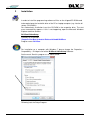
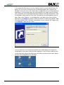
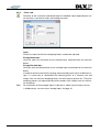
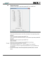
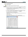
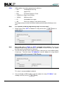
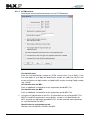
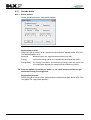
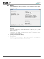
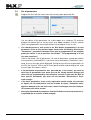
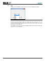
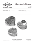
For installation on a computer with Windows 7 please change the Properties –
Compatibility – Privilege Level of the DLXParaV106xxSetup-Software.
Set the mark “Run this program as an administrator”.
Figure 1, Properties
Following start the Setup-Program.
9
2.1
Manually installation
The following paragraphs explain how to install the programming software on a
computer where it was previously not installed and no such directory exists.
Example: Installation from CD drive D: (source drive) onto hard disk drive C: (target drive on
the hard disk), into a newly created directory named "DLXPARA".
10
1.
Insert the CD ROM into the CD drive.
2.
Start the MS Windows Explorer and select the root folder of the drive on which the programming software shall be installed (click on the drive symbol on the left-hand side of
the screen).
3.
Create a new folder named „DLXPARA“ on this drive (File – New – Folder).
4.
Now select the CD drive (click on the symbol with the name „D:“ next to it).
5.
Select all files on the right hand side of the screen and copy them into the newly created
folder named „DLXPARA“.
6.
The programming software is now installed on drive C: in the folder „DLXPARA“.
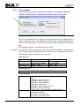
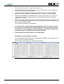
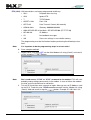
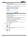
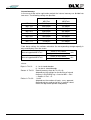
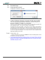
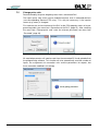
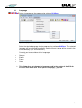
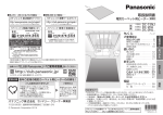
If you would like to be able to start the software without using the MS Windows Explorer, you can create a shortcut on the so called desktop of your computer (the
desktop is what you see on the screen when no applications are running or when all
applications are minimized). Move the mouse pointer to an empty area of the desktop (somewhere over the background image) and press the right hand button. From
the dropdown menu select the item “New” and wait for the next dropdown menu to
open. Now select “Shortcut”. In the dialog that is now open, either enter the complete path to the DLXPara software or click on “Browse” to locate the program. Now
click on the button “Next” and enter a description for your shortcut. We suggest you
use “DLXPara”. Now click on “Finish”.
Figure 2, Creating a shortcut
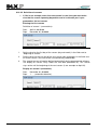
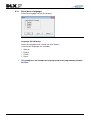
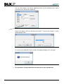
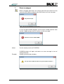
You can move this new shortcut to anywhere on the desktop by pressing the left
hand button on the mouse (while the mouse pointer is over the icon) and then moving the icon while keeping the button pressed. When you release the mouse button,
the icon will be dropped onto the desktop.
Figure 3, Icon on desktop: DLXPara
11
2.2
Update
For an update just overwrite the file DLXPARA.EXE with the new release.
2.3
Uninstalling the program
In order to uninstall you manually have to delete DLXPARA.EXE and the directory
and shortcut you may have created at installation.
2.4
Short description of the DLX device
The DLX was designed as a powerful device for the registration and processing of
electrical impulses from energy meters, flow meters, heat flow processors and similar devices. It is meant for installation in bulk energy supply points, power station injection points, at special contract customers and industrial premises. Load profiles,
calculated values and spontaneous events are processed and stored on the site.
This data can be interrogated by hierarchically higher processing devices via a
number of interfaces.
•
The direct serial service interface (RS232) can be used to read and program the
DLX via the programming software DLXPara. Compatible data retrieval software
(e.g. SIGLON) can be used to read data on site.
•
The data interface (RS232, 20mA/CS, M-Bus or RS485) can be used to retrieve data on site via data retrieval software. Alternatively an external modem can be connected (via RS232).
•
The modem interface can be used to connect via the internal modem (optional) to
the public switched telephone network (PSTN) and data can be uploaded to a PC.
Alternatively it is possible to use ISDN- or Ethernet-Modem.
An optional PC-Card (backup memory) can be used to store the content of the periodical buffers and the spontaneous event buffer as well as part of the device parameters. This PC-Card can be read by compatible data retrieval software via
standard card readers and a PC.
Load management (switching off and on of loads) can be realized on site via external load management software, using the control outputs of the DLX.
12
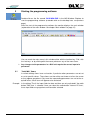
3
Starting the programming software
Double click on the file named “DLXPARA.EXE“ in the MS Windows Explorer to
start the programming software (or double click on the desktop icon, see previous
page).
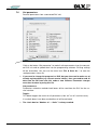
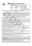
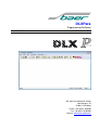
After the start of the programming software the monitor displays the main window
(explanation of the main window: see chapter “Main window” on page 15)
Figure 4, Main window
You can reach the main menu in this window either with the function key “F10“, with
the “hot keys“ or by clicking with the mouse pointer on any of the menu items.
3.1
Any changes to the parameters in a DLX unit require the correct input of a
password
“Invisible“ items
In various dialogs items have no function, if particular other parameters are not set
or set to specific values. These items are then either not shown at all on the screen
or they appear grayed out. Only once the superceding parameters are set to the required values, these items will appear or be activated.
Example: In the dialog "Time" the input fields for date and time are only activated if the radio
button "Edit time“ is selected. Once you select the radio button "Internal PC time“,
these input fields are grayed out and cannot be selected.
13
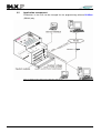
3.2
Application environment
Parameters in the DLX can be changed via the programming software DLXPara
(RS232) only.
Figure 5, Graphical representation of the application environment
14
4
General functions
4.1
Main window
After starting the software, the main window of the programming software is displayed.
The main window contains the menu bar, the task bar and the status bar.
Exit the Program
Maximize window
Name of the active
Parameter file
Minimize window
Menu bar
Toolbar
Status bar
Figure 6, Control elements
4.2
Menu bar
The menu bar is located at the top edge of the window. In the menu bar you can call
up the following main menu items by selecting them with the mouse:
File
Edit
View
Parameter
Connection
?
New
Open…
Save
Save As..
Print…
Print Preview
Print Setup…
Exit
Undo
Cut
Copy
Paste
Tool bar
Status bar
Time
Number of …
Units
Counter values
Pulse in-/outputs
Analog inputs
Control in-/outputs
Scroll List
Registration period
Tariff calendar
Communication
Periodic buffer
Memory
Extra (device display)
Password
Password change
Factory settings
Set all parameters
Change pulse ratio
Get parameters
Port
Language
About para…
4
4
4
4
4
4
4
4
Menu items with an arrow (4) have subsequent menu items.
15
4.3
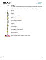
Tool bar
The tool bar is located underneath the menu bar. It contains buttons with icons used
for quick access to menu items. If the mouse pointer comes to rest over a button, a
brief description of that button is displayed after a short period of time.
New file
Open file
Save file
Print
Information about DLXPara
Time
Number of …
Pulse ratio (pulse weighting)
Sum components
Scroll list
Tariff calendar
Communication
Periodic buffer 1 (Load profile 1)
Periodic buffer 2 (Load profile 2)
Password
Set all parameters
Exit software
Select language: German / English / French / Czech
16
4.4
Selecting (menu) items
You have several options how to select a (menu) item of the programming software.
4.4.1
Selection with the mouse
Move the mouse pointer to the desired location and click with the left mouse button.
If you want to edit a value in an input field, you can select and replace the entire
value in that field with a double-click (press the left mouse button twice in quick succession) without having to delete it first (you can recognize this by the change of the
background color). If you only want to edit particular digits of a value, you can place
the cursor with a single click of the left mouse button at the desired position in the
field, but you still need to delete undesired digits (by using the key “Del”)
4.4.2
Selection with the keyboard
Press the function button "F10" to open the menu bar and now use the arrow keys
to select the desired dropdown menu. Once the dropdown menu is open, move the
selection bar with the arrow keys to the desired menu item and press the “Enter”
key.
Within a menu item (i.e. a dialog window) you can jump from one item to the next
with the “Tab” key (you can recognize the currently selected item by the either a
change in the background color or by a surrounding rectangle of dashes).
You can also jump backwards by pressing the “Shift” and the “Tab” key together.
After selecting an item, the complete value in that item (if it is an input field) is automatically selected (you can recognize this by the different background color) and
you enter a new value without having to delete the old one. If you only want to modify a particular digit of the value, you can use the arrow keys (“Left” and ”Right”) to
move the cursor to the desired position, but you still need to delete undesired digits
by using the “Del” key.
4.4.3
Selection with "Hot" keys
You can select menu items by pressing a combination of keys. Press and hold
down the “Alt” key and then press the key with the underlined letter in the desired
menu item.
To edit any values use the methods as described under “Selection with the keyboard”.
17
4.5
Controls
4.5.1
Action buttons
You will find the following action buttons in many dialogs:
Cancel:
If you click on this button (or press “Enter” while this button is selected) all changes
to values will be discarded and the dialog window closes.
Figure 7, Action button “Cancel”
OK:
If you click on this button (or press “Enter” while this button is selected) all changes
to values or settings will be saved in internal memory of your PC and the dialog
window closes.
Figure 8, Action button “OK”
If you want to save the currently set values to the hard disk, you need to select the menu item “Save” or “Save as” before exiting the programming software.
Parameters in the DLX can be changed either via the programming software
DLXPara or via the keypad of the DLX (only certain registers), however any changes to parameters are only possible after input of a valid password. All modifiable parameters are divided into two groups: settable and programmable (a complete list of
all parameters can be found in appendix B of the DLX User Manual). On each
change of a parameter the DLX unit will first check the setting of the program protection switch (located on the backside of the display, see DLX User Manual). If
programming of the unit is disabled (e.g. after the unit has been certified), only settable parameters can be modified. Write access to programmable parameters is only possible after the certification seal has been removed. The device must then be
re-certified, if relevant regulations exist. Once programming of the unit has been
enabled, all parameters can be changed.
18
You should perform a unit restart (to factory default settings) before programming a DLX.
Changes to some of the parameters will trigger automatic erasure of the load
profile memory.
During the transfer of new parameters into the DLX no data retrieval is possible due to data integrity considerations.
The following two action buttons can only be used when a DLX is connected to the
PC (“online programming”):
Set:
If you click on this button (or press “Enter” while this button is selected), settable parameters in the DLX will be changed to the settings in the programming software,
the setting of the program protection switch will not be checked.
Figure 9, Action button “Set”
Set parameter:
If you click on this button (or press “Enter” while this button is selected), programmable parameters in the DLX will be changed to the settings in the programming
software. The program protection switch must be in the position "Set Enable".
Figure 10, Action button “Set parameter”
Note:
The relevant password must be entered correctly before changing any parameters (settable or programmable) in the DLX, otherwise the unit will not
change the parameters and will display a corresponding error message.
During the changing of parameters the DLX automatically switches to the standard
display.
For more information see chapter “Password” on page 83.
19
4.5.2
Selection controls
Radio buttons
Out of a number of radio buttons surrounded by a group rectangle, only one can be
active at any one time.
radio button is active, the related item will be activated during parameter changes.
radio button is inactive, the related item will be deactivated during parameter
changes.
Check boxes
Out of a number of check boxes one or more can be active (checked) at the same
time.
check box is active, the related item will be activated during parameter changes.
check box is inactive, the related item will be deactivated during parameter changes.
You can activate or deactivate these controls by clicking on them with the mouse,
by selecting them via the keyboard or by using the “hot” key for the control.
4.5.3
If you use the keyboard to operate the software, then you need to select each
check box by using the arrow keys and then select the desired state by using
the space bar (each time you press the space bar, the state of the check box
changes).
Once you have selected all the correct values press the “Enter” key to save all
changes to the internal memory of the PC and to close the dialog.
Text input controls with scroll bars
In dialogs supporting the input of values to a number of similar items (e.g. in the dialog “counter values”) you can select the individual items without having to leave the
input field.
To do this, place the cursor into the input field (using the mouse) and enter the value. You can now use the arrow keys (cursor down or up) to select another item in
the scroll box and the input cursor stays in the input field.
20
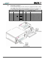
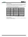
4.6
Connection to the DLX
For the connection between the DLX and the PC a programming cable or modem
cable (#6998, 25 pin SUB-D connector according to ISO2110, pin assignment acc.
To V.24/RS232C/DIN 66020) with the following pin assignments is required:
DLX (25-pin, "female")
In-/Output
Pin-No.
Input
Output
Input
Output
Output
2
3
4
5
6
7
20
Input
cable
PC (25-pin, "male")
PinNo.
2
3
4
5
6
7
20
In-/Output
Signal
Output
Input
Output
Input
Input
TxD
RxD
RTS
CTS
DSR
GND
DTR
Output
(transmit data)
(receive data)
(Request to send)
(Clear to send)
(Data set ready)
(Ground)
(Data terminal ready)
Figure 11, Location of the service interface at the DLX
21
The DLX can be programmed in the following ways:
1.
“Online-programming”: individual parameters are sent directly from the relevant dialog
windows to the DLX by using the action buttons “Set” or “Set parameters” after having
been modified.
2.
By using the menu item “Set all parameters”.
Please proceed as follows:
• Connect the service interface of the DLX with a free COM port of your PC using
a programming cable.
• Put the program protection switch of the DLX into the position “Set Enable” (see
DLX User Manual).
• Create or open a parameter file.
• Enter the valid password (menu item “Password”).
• Program the DLX (menu item “Set all parameters”).
22
5
File
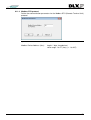
5.1
New
Creates a new (unnamed) parameter file with the default settings of the programming software.
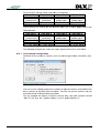
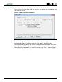
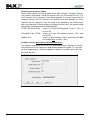
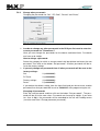
5.2
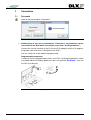
Open…
Opens an existing parameter file.
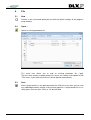
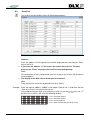
Figure 12, Open a file
This menu item allows you to read an existing parameter file (*.prd).
The four most recently used parameter file names are shown at the bottom of the
“File” menu. If you select any of them it will be opened automatically.
5.3
Save
Saves the parameters in the open parameter file. With this menu item you can save
any modified parameter settings in the currently open file. If no parameter file is currently open, the menu item “Save as” will be activated.
23
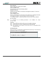
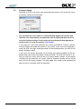
5.4
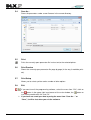
Save As...
Saves the parameters under a new filename in the current directory.
Figure 13, Save file as ...
5.5
Print
Prints the currently open parameter file in clear text to the selected printer.
5.6
Print Preview
Shows the currently open parameter file page by page (in the way it would be printed).
5.7
Print Setup
Allows you to select a printer and a number of other options.
5.8
Exit
If you want to exit the programming software, select the menu item “Exit”, click on
the
button in the upper right hand corner of the main window, the
use the key combination “Alt” and “F4”.
24
button or
If you have not saved your data by using the menu item “Save As…” or
“Save”, it will be lost when you exit the software.
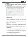
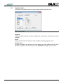
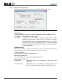
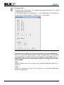
6
Parameter
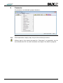
All parameters are collected in groups/submenus.
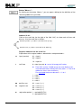
Figure 14, Parameter
Note:
Set the parameters step by step: firstly the time and lastly the extras.
Without input of the correct password for “Parameters” no parameters can be
transmitted to the DLX: for more information see chapter “Password” on page 83.
25
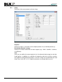
6.1
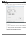
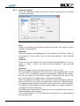
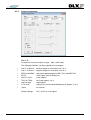
Time
Set the time, parameters for the synchronization and summertime switching including the date and time of the switching.
Figure 15, Setting the time parameters
Time
Internal PC time:
The DLX will be set to the current date and time of the PC where the programming
software is installed.
Edit time:
The DLX will be set to the values entered into the fields “Date” and “Time” at the
time of setting all parameters.
Time/Date:
Input fields for the date and time to be programmed into the DLX.
26
Allow summertime (Automatically adjust clock for Daylight Saving Time)
Activates summertime/wintertime switching.
The switching from summertime to wintertime (and vice versa) happens at the date
and time as defined under “Summertime begins”, “Wintertime begins” and “Day of
switch-over”.
Summertime begins:
Defines the month, weekday and hour of the summertime start.
Wintertime begins:
Defines the month, weekday and hour of the wintertime start. For the start of the
wintertime you must define the time to which the hour will be set, i.e. for a switchover from 03:00 to 02:00 you must define the value “2” for the hour.
Day of switchover:
Defines the day for the summertime/wintertime switching.
In our example (see Figure 15, Setting the time parameters) the following switchovers will happen:
Wintertime to summertime: last Sunday in March from 02:00 to 03:00
Summertime to wintertime:
last Sunday in October from 03:00 to 02:00
Synchronization window:
Defines the period of time (time window) during which synchronization via the SYN
input is possible. If you enter a value between 1 and 29 (in seconds) then synchronization to the closest full minute is only possible in this time window around the end
of registration period MP1.
Alarm-free:
Inside synchronization window an alarm-free window can be defined. When the DLX
is synchronized out of the alarm-free window (but inside the synchronization window) a warning is generated (alarm number: 07/02)
Note:
If you set the synchronization time to “0”, you can always synchronize to the closest
full minute.
Example: Sync window:
Alarm-free:
Registration period:
10 seconds
10 seconds
Tm1 = 15 minutes
→ Synchronization only permitted in a window of +/- 10 seconds around
each full 15 minutes (where minutes = 0 or 15 or 30 or 45).
DLX firmware releases up to and including 1.04.00 didn’t support the sync
window (alarm-free only). For release including 1.04.01 and up set the version-mark.
27
Synchronization
No synchronization:
Incoming pulses at the SYN input have no effect on the time.
SYN input:
Incoming pulses at the SYN input set the seconds in the DLX to “0” (see also menu
item “Control inputs” on page 43).
External radio clock:
The DLX will be synchronized by the external (DCF77) radio clock receiver module
(currently to “0” seconds only).
Note:
Synchronisation one time per measuring period only.
Example:
SYN input active at..
Date
Time
2002-12-31
23:59:55
2003-01-01
00:00:05
2002-12-31
23:59:29
2002-11-28
11:54:30
The DLX will set the time to..
Date
Time
2003-01-01
00:00:00
2003-01-01
00:00:00
2002-12-31
23:59:00*
2002-11-28
11:55:00*
* Synchronization to a minute that is not identical with the end of registration period
is only possible if the synchronization window is set to ‘0’.
The SYN input and the radio clock receiver module of the DLX cannot detect
whether the internal device time is set properly (date, hours, and minutes)!
The unit will only set the seconds to “0” and the minute to the closest minute
value (see table above)!
Set time via SCTM:
Enables the transfer of date and time during remote data retrieval when using the
SCTM protocol (e.g. via modem). Per registration period (Tm1) is only one attempt (for
set time) possible.
28
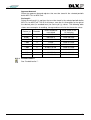
6.2
Number of …
Definition of the number of inputs, tariff rates, summation units, apparent demand
and balance calculation.
After every change set all parameters: see chapter “Set all parameters” on page 88.
Figure 16, Number of inputs, sums, tariff rates
Total number of inputs:
Defines the number of inputs in the DLX: pulse inputs and analogue inputs. This
number must be between 1 and the number of physically available inputs (max. 16)!
If your DLX unit is equipped with only 6 input modules, then this number must be
between 1 and 6!
Sums:
Defines the number of summation units in the DLX (between 0 and 4). If you set this
figure to “0”, no summation will take place.
Cosine Phi:
Defines the number of apparent demand units and cosine phi (ϕ) units in the DLX
(between 0 and 2). If you set this figure to “0”, no apparent demand or cosine phi
(ϕ) will be calculated.
Energy tariff rates:
Defines the number of energy tariff rates. This figure must be between 1 and 4!
Demand tariff rates:
Defines the number of demand tariff rates. This figure must be between 1 and 4!
Balance:
Activates the calculation of the differential balance (for demand values only).
The DLX calculates the difference (or balance) between the total demand in forward
direction and the total demand in backward direction and stores the result at the end
of registration period (!) in the relevant register of the summation unit. The other
register of that summation unit will then contain the value “0”.
1 minutes summation (option, on request):
Calculation for energy and MD only at the end of every minute (Tm1 and Tm2)
29
6.3
Units
Definition of the measurement unit text strings
Figure 17, Measurement unit text strings
Register:
Selects the inputs, summation unit or complex power unit (as defined previously)
Resolution demand / energy:
Selects the number of decimals for each register (e.g.: 12kW, 12,3kWh, 12,34kvar,
12,345kvarh).
Unit:
Here you can define the correct physical unit for demand and energy for each defined register. In addition to a selection of frequently used units for active, reactive
and apparent energy/demand another 5 unit text strings can be defined and used
freely (e.g.: m3/h, m3, t, K, C). Special characters are not possible (e.g. m³)!
30
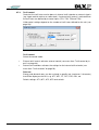
6.4
Counter values
Definition of the counter values for total energy and for each tariff rate.
Figure 18, Counter values
Register:
Select the input for which you want to adjust the energy value (the counter or meter
reading).
Tariff:
Select the tariff rate for which you want to adjust the energy register value.
Energy value:
Here you can define the energy value (the register or meter reading) for the selected input or register. You can use the value “000000000” (9 digits) as start value.
31
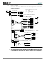
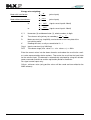
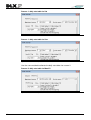
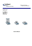
6.5
Pulse in-/outputs
All impulses at the inputs will be counted after debouncing and then processed according the table below.
Pulses
Momentary
value
Energy
Input 1..16
XIn1
The following registers {REG} are used for results : (see Appendix B)
For register addresses the following sub-addresses are possible:
ee = 01..16 Inputs 1..16
pp = 01..04 Total forwards 1..4 (positive)
nn = 01..04 Total backwards 1..4 (negative)
Energy registers cumulative
total
YIn1
100-ee
190-ee
current
last MP1
AT
Energy registers for current
total
XIn16
250-ee
YIn16
current
220-ee
last MP1
AT
101-ee
102-ee
103-ee
104-ee
191-ee
192-ee
193-ee
194-ee
current
last MP1
251-ee
252-ee
253-ee
254-ee
221-ee
222-ee
223-ee
224-ee
current
last MP1
rate 1
rate 2
rate 3
rate 4
REG{100-ee} = IEee × REG{30000-ee} ⁄ REG{30100-ee}
rate 1
rate 2
rate 3
rate 4
REG{250-ee} = IEee × REG{30000-ee} ⁄ REG{30100-ee}
REG{110-pp} = ( Σ ±REG{100-ee} ) cumulative
REG{260-pp} = ( Σ ±REG{100-ee} ) current
1
Pulses
29200-pp
Energy total
1…4
110-pp
200-pp
current
last MP1
+1
0
-1
Hysteresis: 29300-pp
60
MP1
230-pp
last MP1
current
last MP1
AT
261-pp
262-pp
263-pp
264-pp
231-pp
232-pp
233-pp
234-pp
current
last MP1
AT
121-nn
122-nn
123-nn
124-nn
211-nn
212-nn
213-nn
214-nn
current
last MP1
271-pp
272-pp
273-pp
274-pp
241-pp
242-pp
243-pp
244-pp
1
+1
0
-1
Demand /
Increment
Input 1..16
260-pp
current
AT
111-pp
112-pp
113-pp
114-pp
29200-pp
Registration period MP1
131-ee
161-ee
current
last MP1
MT
120-nn
210-nn
current
last MP1
201-pp
202-pp
203-pp
204-pp
rate 1
rate 2
rate 3
rate 4
IApp +
Momentary
value
Forward
rate 1
rate 2
rate 3
rate 4
Pulses
rate 1
rate 2
rate 3
rate 4
Pulse output
Pulse inputs
In1 to In16
IAnn -
Momentary
value
Backward
rate 1
rate 2
rate 3
rate 4
270-nn 240-nn
current
last MP1
AT
REG{120-nn} = ( Σ±REG{100-ee} ) cum.
current
last MP1
REG{270-nn} = ( Σ±REG{100-ee} ) curr.
Maximum demand
Total
300-ee
301-ee
rate 1
REG{131-ee} = {DIFFMP1} REG{100-ee} × 60 ⁄ MP1
rate 2
302-ee
REG{131-ee} = {DIFFMP1} REG{100-ee}
rate 3
303-ee
rate 4
304-ee
for demand
for increment
Value + Time
Demand /
Increment
Total 1..4
REG{141-pp} = ( Σ±REG{131-ee} )
+1
0
-1
141-pp
current
171-pp
last MP1
MT
Maxima
310-pp
Total
311-pp
rate 1
312-pp
rate 2
313-pp
rate 3
314-pp
rate 4
Value + Time
Forward
Maxima
Total
320-nn
rate 1
321-nn
rate 2
322-nn
rate 3
323-nn
rate 4
324-nn
Value + Time
Backward
Balance: 31000-04
+1
0
-1
132-ee
162-ee
current
last MP2
181-nn
last MP1
MT
REG{151-nn} = ( Σ±REG{131-ee} )
Registration period MP2
60
MP2
151-nn
current
REG{132-ee} = {DIFFMP2} REG{100-ee} × 60 ⁄ MP2
REG{132-ee} = {DIFFMP2} REG{100-ee}
+1
0
-1
for demand
for increment
REG{142-pp} = ( Σ±REG{132-ee} )
142-pp
172-pp
current
last MP2
152-nn
182-nn
current
last MP2
Balance: 31000-04
+1
0
-1
REG{152-nn} = ( Σ±REG{132-ee} )
Figure 19, Block circuit diagram of impulse processing
32
Any calculation of values for registration period 2 (MP2/Tm2) only takes place
if a period duration other than 0 was defined in the menu item “Load profiles”.
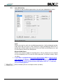
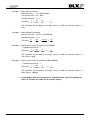
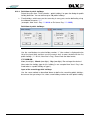
6.5.1
Input debouncing
Definition of input conditioning parameters for each input (dependent of meter).
Figure 20, Input debouncing
Input:
Selects the input for which the conditioning parameters shall be displayed and defined. Each input can have its own settings for signal conditioning. Select the required input and then define the minimum time for HIGH and LOW phases as well
as the maximum time for the HIGH phase.
Minimal HIGH-Phase:
Defines the minimum length of incoming pulses. Pulses shorter than this duration
are not accepted by the DLX and will not be registered. The default setting is 30ms
(3×10ms).
If your DLX is equipped with bi-current input modules (IED) or signal current
input modules (0..20mA or 4..20mA up to firmware version 1.05.06), then for
these inputs you must set the minimum HIGH phase value to “1” to prevent
loss of incoming pulses!
With this button you can set all inputs to 10ms (or 30ms).
33
Minimal LOW-Phase:
Defines the minimum length of the interval between two incoming pulses. Intervals
shorter than this time will not be accepted by the DLX and as a consequence the
pulses will not be counted separately. The default setting is 30ms (3×10ms)
If your DLX is equipped with bi-current input modules (IED) or signal current
input modules (0..20mA or 4..20mA up to firmware version 1.05.06), then for
these inputs you must set the minimum LOW phase value to “1” to prevent
loss of incoming pulses!
Maximal HIGH-Phase:
If an incoming pulse has a duration longer than this value, the DLX will not register it
(pulse length monitoring). This function is deactivated by entering the value “0”.
Invert input:
By default the DLX counts pulses on their rising edge. When you select to invert an
input then pulses will be counted on their falling edge.
Example: Standard pulse:
Inverted pulse:
(Change from LOW to HIGH-Phase)
(Change from HIGH to LOW-Phase)
Pulse barrier:
With pulse barrier enabled all pulses arriving in a time window around the end of
registration period (Top) are buffered. These are forwarded in the next registration
period, synchronizing all following devices. This is done to accomplish identical figures at main and control measurement.
This can cause pulses appear as packets at pulse outputs and summation
registers!
Features:
•
•
•
individually configurable for every input
time range: +/- 9.9 s around end of registration period (Top)
settable in steps of 100 ms
Instantaneous value (MP1 / 1min):
For special calculation (e.g. fill level, fluid level, temperature) at the end of registration period it is possible to activate the measuring for the last minute in every registration period. This function can be activated only for registration period MP1/Tm1
(Buffer 1)
34
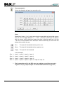
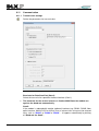
6.5.2
Pulse ratio
Definition of the numerator and denominator of individual inputs depending on meter constants, transformer ratios and reading constants.
Figure 21, Pulse ratio
Input:
Selects the input for which the weighting factors need to be adjusted.
Energy-Numerator:
Here you enter the numerator for the selected input, calculated from the formulas
below.
Energy-Denominator:
Here you enter the denominator for the selected input, calculated from the formulas
below.
In order to correctly calculate the energy represented by input signals of different origins it is necessary to standardize the incoming pulses to a common unit and
weight. You use the pulse weighting factors for each input to achieve this. The pulse
weighting factors are represented by whole numbers with 8 digits each for numerator and divisor.
Note:
For calculation of the analogue inputs 0..20mA or 4..20mA (from firmware version
1.06.00 and up): see menu item “Analog inputs” on page 42.
35
Energy value weighting:
Meter with transformer:
X
W
=
Y R ×K
(pulse inputs)
Meter without transformer:
X Const
=
Y
K
(pulse inputs)
or
X
DIFF
(signal current input 0..20mA)
=
Y 72000 × K
or
X
DIFF
(signal current input 4..20mA)
=
Y 57600 × K
X, Y
Numerator (X) and denominator (Y), whole numbers, 8 digits
W
Transformer ratio (primary to secondary):
R
Meter constant (e.g. Imp/kWh), can be found on the front plate of the
transmitting meter.
Reading constant, usually assumed to be K = 1
Impulse constant (e.g. kWh/Imp)
Transducer range (max. valueencoder - min. valueencoder) := 20Hz
K
Const
DIFF
Upri
Usec
×
Ipri
Isec
Enter the correct values into the above formulas and reduce the result to the smallest value represented by whole numbers. Then enter the result into the input fields
for the relevant input. The demand is automatically calculated by using the ratio between numerator and divisor and the registration period in the device.
For signal current inputs only:
Offset:= minimum value (only positive values will be saved and transmitted to the
AMR software)
36
Example 1: Meter with transformer
Meter constant:
R = 300 Imp/kWh
Transformer ratio:
W = 200
Reading constant: K = 1
Therefore:
X
Y
=
200
300 × 1
=
200
300
2
or =
3
The resolution for the display of energy values is 1kWh, for demand values it is
1kW.
Example 2: Meter without transformer
Impulse constant:
Const = 2,5 kWh/Imp
Reading constant: K = 1
Therefore:
X
Y
=
2,5
1
=
2,5 × 10
1× 10
=
25
10
Example 3: Signal current input: 0..20mA with 0..3500kW
→ Reading constant K = 1
Therefore:
X
Y
=
3500
72000×1
=
35
720
or =
7
144
The resolution for the display of energy values is 1kWh, for demand values it is
1kW; offset:= 0kW
Example 4: Signal current input: 0..20mA with 1000..4500kW
→ Reading constant K = 1
Therefore:
X
Y
=
3500
72000×1
=
35
720
or =
7
144
The resolution for the display of energy values is 1kWh, for demand values it is
1kW; offset:= 1000kW
If you need to total several inputs in a summation unit, then the reading constant “K” must be the same for all of these inputs!
37
6.5.3
Sum components
Define the allocation of inputs to summation units
Figure 22, Input allocation to sums
Sum:
Allocation of inputs (1 to 16, only pulse inputs are possible) to the desired summation unit. You can toggle between “+”, “-“ and “ “ (inactive) by clicking on the buttons
with the mouse or by selecting a button and then using the space bar. Use the
“Tab” key to move between rows of buttons and the arrow keys to move from one
button to next within the row.
Plus
The input will be totaled into the positive sum.
Minus
The input will be totaled into the negative sum.
Empty
The input will not be totaled.
In our example:
Sum 1 = Input 1 + Input 2 + Input 3 + Input 4
Sum 2 = Input 1 + Input 2 − Input 5 − Input 6
Sum 3 = Input 1 − Input 5 + Input 9 − Input 11
Sum 4 = Input 1 + Input 2 + Input 3 + Input 4 + Input 9 + Input 10
38
Each summation unit in the DLX uses two registers: a positive sum and a
negative sum (e.g. import/export for forward and backward energy flow)
6.5.4
Summation outputs
Define the output pulse length, the hysteresis and the nominator for the selected
summation unit output.
Figure 23, Summation outputs
Sum:
Select the summation unit for which the output pulse length, the hysteresis and the
nominator shall be defined.
HIGH-time:
Defines the length of the outgoing pulses. The resolution for the values is 10ms (in
this example: 9 × 10ms = 90 ms). You can enter values between 1 (10ms) and 200
(2000ms).
LOW-time:
Defines the minimum length of the interval between two outgoing pulses (in this example: 11 × 10ms = 110 ms). You can enter values between 1 (10ms) and 200
(2000ms).
Hysteresis:
Defines the capacity of the slack register (Hysteresis: kWh or kvarh).
For the calculation of balanced sums the DLX can use a programmable slack or
hysteresis. This is a temporary storage for incoming pulses. With each pulse of positive sign the content of the hysteresis register is increased by the value of that
pulse, with each pulse of negative sign it is decreased accordingly.
Pulses only appear at the output of the summation unit once the programmable capacity of the hysteresis has been exceeded either in positive or negative direction.
An integrated energy direction switch directs the pulses in the first case to the positive output and in the second case to the negative output (see “Figure 19, Block circuit diagram of impulse processing”).
We recommend using a hysteresis equal to the sum of numerators (from the pulse
weighting dialog) of all active inputs.
If you set the hysteresis to “0”, the calculation of balanced sums is deactivated for
that summation unit.
39
Pulse output:
Defines the value for the weighting of output pulses. The resolution and physical
unit are the same as for the reading constant “K”. (see “Pulse ratio” on page 36)
Example: Reading constant
K = 1 (for active energy: 1kWh)
Pulse output
Out = 2 × 1kWh/Imp
→ each output pulse has the weight 2kWh/Imp (:=0.5 Imp/kWh)
40
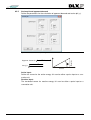
Cosine phi and apparent demand
Define the parameters for the calculation of apparent demand and cosine phi (ϕ).
Figure 24, Calculation of cosine of phi and apparent demand
Apparent demand = Active 2 + Reactive 2
Cos(ϕ ) =
Reactive
6.5.5
Active 2
Active 2 + Re active 2
Active
Active input:
Define the source for the active energy: this can be either a pulse input or a summation unit.
Reactive input:
The correlated source for reactive energy: this can be either a pulse input or a
summation unit.
41
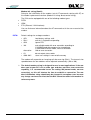
6.6
Analog inputs
A continuous signal current flow is applied to the signal current inputs (e.g. 0..20mA
or 4..20mA). This current is proportional to the actual demand. For firmware version
from 1.06.00 and up: the average value (50 scans per second) will be send every
second to the DLX-CPU: digital telegram.
Figure 25, Analog inputs
Select the settings for every analog input:
•
•
•
•
Minimum and maximum value;
Set the offset 0mA or 4mA (correspond to the minimum value)
20mA correspond to the maximum value;
Calculation method: average value (over a measuring period) or instantaneous
value (last data telegram at the end of measuring period);
Offset:= minimum value (only positive values will be saved and transmitted to the
AMR software)
Note:
Summation of the digital values is not possible!
Examples:
Signal current input: 4..20mA with 0..10m³/h (e.g. flow)
Reading constant K = 0,1; offset = 0m³/h
→ Minimum value:= 0
Maximum value:= 100 (100 × 0,1m³/h = 10m³/h)
data storage:= 0
data storage:= 100
Signal current input: 4..20mA with 20..50m (e.g. water level)
Reading constant K = 1; offset = 20m
→ Minimum value:= 20 (20 × 1m = 20m)
Maximum value:= 50 (50 × 1m = 50m)
data storage:= 0
data storage:= 30
Signal current input: 0..20mA with -20°C..70°C (e.g. temperature)
Reading constant K = 0,1; offset = -20°C
→ Minimum value:= -200 (-200 × 0,1°C = -20°C)
Maximum value:= 700 (700 × 0,1°C = 70°C)
Note:
42
data storage:= 0
data storage:= 900
Minimum value:= 0 and Maximum value:= 50 → analog input deactivated;
6.7
Control in- and outputs
6.7.1
Control inputs
Setting the parameters for control inputs:
Figure 26, Control inputs
As an option the DLX can be fitted with several control inputs. Depending on the
hardware version the following functions can be activated:
Reset disabled for… (MP1):
Defines the period of time during which no reset can be initiated (in registration periods MP1). The value can be set between 1 and 100 registration periods (value 0 is
not permitted!).
Example: The registration period MP1 is set to 15 minutes, the reset is disabled for 3 registration periods: this results in a blocking time of 45 minutes for the reset.
Reset counter:
Defines the initial value for the reset counter (a value between 1 and 12). The reset
counter will be increased by 1 on each reset. It rolls automatically over to the value
1. The reset counter can (as an example) be set equal to the current month.
43
Time for scroll button:
Defines the period of time between automatic scrolls to the next register address in
the scroll list after pressing the “Enter” key on the DLX. If you set this value to “0”
then automatic scrolling is disabled and the next entry in the scroll list is only displayed on the next press of the “Enter” key. The time is measured in seconds. The
maximum time that can be defined is 240 seconds.
SYN edge:
Defines the polarity of the SYN input.
Default setting: synchronization on the rising (positive) edge of a pulse.
This control is only active once the SYN function is assigned to a control input.
Input Ctl1 to Ctl7:
Define the assignment of functions to control inputs. The following functions are
available:
•
•
•
•
•
•
SYN:
TR1 to TR4:
RSTX:
Log 1 to Log 4:
ANZ (ROLL):
(none)
external synchronization
control inputs for external tariff rate control
external reset
logic inputs; changes to these inputs can be stored.
scrolling the display via an external signal
no function
Automatic reset:
Defines the time for automatic resets (billing list):
44
•
No automatic reset
•
Daily reset / billing list (Enter: hour, minute)
•
Weekly reset / billing list (Enter: hour, minute and weekday)
•
Monthly reset / billing list (Enter: hour, minute and day)
•
Yearly reset / billing list (Enter: hour, minute, day and month )
6.7.2
Output assignments
Figure 27, Assignment of signals to outputs
Out 1 - 4:
Assignments for pulse outputs of type “wipe” (solid state).
The following functions can be assigned to these outputs:
•
•
•
•
•
•
•
•
•
Sum1+ to Sum4+:
Sum1– to Sum4 –:
MPA1 and MPA2:
RSTA:
Alarm 1 and 2:
TRA1 to TRA4:
Log1 to Log4:
In1 to In16:
(none)
positive output of summation unit 1 to 4
negative output of summation unit1 to 4
registration period output for MP1/Tm1 and MP2/Tm2
reset output (time for billing list)
alarm outputs
tariff rate outputs 1 to 4
logic outputs
input pulses can be forwarded directly to outputs (1 to 1)
no function
Default settings:
Out 1 to Out 4: unassigned
45
Rel 1 and Rel 2:
Assignments for mechanical relay outputs.
The following functions can be assigned to each relay output:
•
•
•
•
•
•
MPA1 and MPA2:
RSTA:
Alarm 1 and Alarm 2:
TRA1 to TRA4:
Log1 to Log4:
(none)
default settings:
registration period output MP1/Tm1 and MP2/Tm2
reset output (time for billing list)
alarm outputs
tariff rate outputs 1 to 4
logic outputs
no function
Rel 1: Alarm 2
Rel 2: MPA1
Outputs of summation units cannot be assigned to mechanical relay outputs.
For some output functions the type of output signal can be defined:
•
Pulse:
•
Switch:
pulse with variable length (in steps of 200ms for MPA and
RSTA or in steps of 1 sec for alarms)
permanent state until the signal changes.
Time MPA:
Defines the length of time for which the registration period output shall be active at
the end of a registration period. The typical value for MPA is 9 seconds (this corresponds to 45 x 200ms). The highest value for MPA is 20 seconds (this corresponds
to 100 x 200ms). This value can only be set once MPA (MPA1 or MPA2) is assigned to an output. Possible values: 1 to 100.
Reset output:
Defines the mode for the RSTA output: pulse or switch. This can only be defined
once RSTA is assigned to an output.
RSTA pulse length:
Defines the pulse length for the reset signal (for billing list). The typical value is 9
seconds (this corresponds to 45 × 200ms). The highest value is 20 seconds (this
corresponds to 100 × 200ms). This can only be defined once RSTA is assigned to
an output. Possible values: 1 to 100.
Alarm 1 or Alarm 2:
Defines the mode for Alarm 1 or 2: pulse or switch. This can only be defined once
alarm signals are assigned to an output.
Alarm 1 or Alarm 2 pulse length:
Defines the pulse length for the alarm signals. The value set must be between 1
and 254 seconds. This can only be defined once alarm signals are assigned to an
output.
46
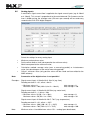
6.7.3
Tariff control
Control of the tariff rates can be done via internal tariff calendar or external signals
(e.g. ripple control receiver or radio clock). If external tariff control is activated then
the tariff rates are defined by 4 control inputs (TR1, TR2, TR3 and TR4).
Valid control settings depend on the number of tariff rates defined for the unit (see
page 29)!
Figure 28, Tariff control
Tariff control
Select the control mode:
•
External tariff control: activates external control (see menu item “Tariff control by inputs” on page 48).
•
Internal tariff calendar: activates the settings for the internal tariff calendar (see
menu item “Tariff calendar” on page 56).
Rate text
Energy and demand rates can be assigned a specific text (maximum 3 character)
that will be display on the DLX, e.g. AT1, MT1, PT, DPT, ER1, DR1, etc.
Default settings: AT1, MT1, AT2, MT2 and so forth.
47
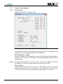
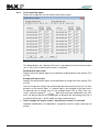
6.7.4
Tariff control by inputs
Define the assignments for the external tariff control inputs
Figure 29, Tariff control by inputs
This dialog defines the setting of tariff rates in correlation to external control signals
(this is only useful if external tariff control is activated)
Demand tariff input mask:
Defines the active control inputs for the definition of demand tariff rate settings (TR1
to TR4).
Energy tariff input mask:
Defines the active control inputs for the definition of energy tariff rate settings (TR1
to TR4).
You can assign one energy rate and one demand rate to each of the max. 16 combinations of rate control inputs. If a control input is not activated in the input masks
for demand rates or energy rates (in the example above TR2 to TR4), then it assumes a default setting of “
“. More than one input combination (e.g. MT1
and ) can be possible for one combination of demand rate and energy rate (e.g. in
the picture above lines 1 and 5 in both the right and left column).
These settings will only be used if “external tariff control” is activated.
Individual combinations are depicted in a graphical manner: control input open or
closed.
48
6.8
Scroll list
The scroll list can only display values for information purposes!
Figure 30, Scroll list
Address:
Enter the address of the register that shall be displayed after pressing the “Enter”
key on the DLX.
If you enter the address “0” this means the end of the scroll list. The next
press on the “Enter” key starts the scroll list from the beginning.
Text:
For the purpose of easy interpretation you can assign a text of max. 20 characters
to each address.
The display of the DLX cannot show special characters.
Unit:
Enter the physical unit of the displayed value (e.g. "kWh").
Example: Enter the register address “84000” in the address field of line 11 and enter the text
“Date of last reset” in the text field next to it.
After programming the DLX and starting the scroll list with the
key, the 11th
position in the scroll list will show the following display:
D DM ONY Yu HH :M M: ss rp sp
AT x M Tx
MP x YY x x
D at e o f la st r es et
NR
DD MO NY Y HH :M M
1. Line (standard display)
2. Line (standard display)
3. Line (text of scroll list)
4. Line (value and possible unit of the value)
49
Button "More>>":
By clicking on the button “More>>” you can open a dialog for the definition of the
remaining addresses (up to 40).
Figure 31, Button "More>>"
Address 21-40:
Click on the scroll bar (to the right of the field “Unit”) to show each of these addresses. Use the scroll bar as follows:
Go to the previous (-1) address (also with cursor up key)
Go to the next (+1) address (also with cursor down key)
Register addresses for the scroll list
Explanation of the register address abbreviations and placeholders:
cc
input (counter)
01 = input 1
02 = input 2
…
16 = input 16
t
tariff rate
0 = total (no rate): ► sum of all energy tariff values
► From DLX version 1.04.00 up you can also display maximum demand values without tariff rate (totals; t := 0 to 4 for
addresses 3xtxx, 4xtxx and 5xtxx).
For cumulated maximum demand: t := 1 to 4
1 = rate 1
2 = rate 2
3 = rate 3
4 = rate 4
50
pp
positive sum
01 = sum 1 (+/−)
nn
negative sum
02 = sum 2 (+/−)
03 = sum 3 (+/−)
04 = sum 4 (+/−)
m
registration period 1 = period MP1/Tm1
2 = period MP2/Tm2
Current cumulated energy values
Address
10tcc
11tpp
12tnn
Description
Current energy value for input (cc) and tariff rate (t)
Current energy value for the positive sum (pp) and tariff rate (t)
Current energy value for the negative sum (nn) and tariff rate (t)
Current demand values (analogue inputs: version 1.06.00 and up)
Address
13mcc
136cc
137cc
138cc
14mpp
15mnn
Description
Current demand value for registration period (m) for input (cc)
Analogue inputs: instantaneous value, from version 1.06.00 and up
Analogue inputs: average value for registration period Tm1
Analogue inputs: average value for registration period Tm2
Current demand value for registration period (m) for positive sum (pp)
Current demand value for registration period (m) for negative sum (nn)
Demand values for the most recent registration period
Address
16mcc
17mpp
18mnn
Description
Demand value for the most recent registration period (m) for input (cc)
Demand value for the most recent registration period (m) for positive sum (pp)
Demand value for the most recent registration period (m) for negative sum (nn)
Cumulative energy values for the most recent registration period MP1/Tm1
Address Description
19tcc
Cumulative energy value for the most recent period MP1 for input (cc) and tariff rate (t)
20tpp
Cumulative energy value for the most recent period MP1 for positive sum (pp) and tariff
rate (t)
21tnn
Cumulative energy value for the most recent period MP1 for negative sum (nn) and tariff
rate (t)
Current energy values for the most recent registration period MP1/Tm1 since
last reset
Address
22tcc
23tpp
24tnn
Description
Current energy value since last reset for MP1 for input (cc) and tariff rate (t)
Current energy value since last reset for MP1 for positive sum (pp) and tariff rate (t)
Current energy value since last reset for MP1 for negative sum (nn) and tariff rate (t)
Current energy values since last reset
Address
25tcc
26tpp
27tnn
Description
Current energy value since last reset for MP1 for input (cc) and tariff rate (t)
Current energy value since last reset for MP1 for positive sum (pp) and tariff rate (t)
Current energy value since last reset for MP1 for negative sum (nn) and tariff rate (t)
51
Maximum demand and timestamp for the current reset period (current maximum), without unit
Address Description
30tcc 1) Maximum demand and timestamp for the current reset period for tariff rate (t) and input
(cc)
1)
31tpp
Maximum demand and timestamp for the current reset period for tariff rate (t) and positive sum (pp)
32tnn 1) Maximum demand and timestamp for the current reset period for tariff rate (t) and negative sum (nn)
Maximum demand and timestamp for the last reset, without unit
Address Description
33tcc 1) Maximum demand and timestamp for the last reset for tariff rate (t) and input (cc)
34tpp 1) Maximum demand and timestamp for the last reset for tariff rate (t) and positive sum
(pp)
35tnn 1) Maximum demand and timestamp for the last reset for tariff rate (t) and negative sum
(nn)
Cumulated maximum demand for the last reset period
(version 1.05.02 and up)
Address
36tcc
37tpp
38tnn
Description
Cumulated maximum demand for the last reset for tariff rate (t) and input (cc)
Cumulated maximum demand for the last reset for tariff rate (t) and positive sum (pp)
Cumulated maximum demand for the last reset for tariff rate (t) and negative sum (nn)
Maximum demand of the current reset period (current maximum)
Address
40tcc
41tpp
42tnn
Description
Maximum demand of the current reset period for tariff rate (t) and input (cc)
Maximum demand of the current reset period for tariff rate (t) and positive sum (pp)
Maximum demand of the current reset period for tariff rate (t) and negative sum (nn)
Maximum demand of the most recent reset
Address
43tcc
44tpp
45tnn
52
Description
Maximum demand at most recent reset for tariff rate (t) and input (cc)
Maximum demand at most recent reset for tariff rate (t) and positive sum (pp)
Maximum demand at most recent reset for tariff rate (t) and negative sum (nn)
Cumulated maximum demand for the second last reset period
(version 1.05.02 and up)
Address Description
46tcc
Cumulated maximum demand for the second last reset for tariff rate (t) and input (cc)
47tpp
Cumulated maximum demand for the second last reset for tariff rate (t) and positive sum
(pp)
48tnn
Cumulated maximum demand for the second last reset for tariff rate (t) and negative
sum (nn)
Timestamp of the current maximum demand
Address Description
50tcc
Timestamp for the current maximum demand for tariff rate (t) and input (cc),
see address 40tcc
51tpp
Timestamp for the current maximum demand for tariff rate (t) and positive sum
(pp), see address 41tpp
52tnn
Timestamp for the current maximum demand for tariff rate (t) and negative sum
(nn), see address 42tnn
Timestamp for the maximum demand of the most recent reset
Address Description
53tcc
Timestamp for the maximum demand of the most recent rest for tariff rate (t) and input
(cc), see address 43tcc
54tpp
Timestamp for the maximum demand of the most recent rest for tariff rate (t) and positive sum (pp), see address 44tpp
55tnn
Timestamp for the maximum demand of the most recent rest for tariff rate (t) and negative sum (nn), see address 45tnn
Cumulative energy values at most recent reset
Address
60tcc
61tpp
62tnn
Description
Cumulative energy value at most recent reset for tariff rate (t) and input (cc)
Cumulative energy value at most recent reset for tariff rate (t) and positive sum (pp)
Cumulative energy value at most recent reset for tariff rate (t) and negative sum (nn)
Current energy values at most recent reset
Address
63tcc
64tpp
65tnn
Description
Current energy value at most recent reset for tariff rate (t) and input (cc)
Current energy value at most recent reset for tariff rate (t) and positive sum (pp)
Current energy value at most recent reset for tariff rate (t) and negative sum (nn)
53
Other register addresses
Address
1)
70001
1)
83200
1)
83201
1)
84000
1)
54
Description
Firmware version
Unit identification (16 digits), from version 1.05.06 and up
Serial number (6 digits), from version 1.05.06 and up
Number and timestamp of the most recent reset
For these items the display will not show physical units!
6.9
Registration period
Definition of the length of registration periods MP1/Tm1 and MP2/Tm2
Figure 32, Registration periods
Registration of demand values in the DLX can be done in two registration periods.
Period 1:
Defines the length of registration period MP1/Tm1.
Resets and maximum demand calculation are only done for registration period MP1.
Period 2:
Defines the length of registration period MP2/Tm2.
Start of Period:
Defines the start time of registration period MP2/Tm2 in full hours.
Example: Registration period 2 (MP2/Tm2) = 24 hours
Start of period = 06:00 (for CET = Central European Time: wintertime)
The calculation of values for registration period MP2/Tm2 starts at 06:00 for the
next 24 hours.
This item can only be selected of registration period 2 (Tm2) is set to 24
hours.
55
6.10
Tariff calendar
You must select the item “Internal tariff calendar” in the dialog “Control in/outputs 4 Tariff control” to activate the internal tariff rate calendar.
Figure 33, Tariff rate control
You can use the dialog “Tariff calendar” to define the device internal switching times
for the various tariff rates. This dialog allows you to create a number of different rate
tables for different periods of time (e.g. summertime and wintertime) for one whole
year.
The following example is used to illustrate the usage:
Example
Two different seasons (wintertime and summertime) with different switching times
for two energy rates and two demand rates (Peak time “PT” and Normal time “NT”).
The following settings (switching times) are used:
Peak time “PT”
Season:
Time period:
Summertime
April 01 (00:00) to
November 01 (00:00)
06:00 – 21:00
06:00 – 13:00
MO – FR (PT):
SA (PT):
Wintertime
November 01 (00:00) to
April 01 (00:00)
06:00 - 18:00
06:00 - 13:00
Normal time “NT”
All other time periods (incl. Sundays and public holidays)
Public holidays
Holiday type 1:
Holiday type 2:
56
Tariff rate structure like Sunday (Normal time “NT”
only):
01.01.2011 (New Year’s Day),
22.04.2011 (Easter Friday),
25.04.2011 (Easter Monday),
01.05.2011 (Labor Day),
02.06.2011 (Resurrection of Christ),
13.06.2011 (Whitsun Monday),
25./26.12.2011 (Christmas Day and Boxing Day).
Tariff rate structure like Saturday (Peak time “PT”
from 06:00 to 13:00):
24.12.2011 (Christmas Eve),
31.12.2011 (New Year’s Eve).
For these tariff settings 4 daily rate tables are required:
Rate table 1
Rate table 2
Rate table 3
Rate table 4
MO-FR
MO-FR
SO
SA
(summertime)
(wintertime)
holiday type 1
holiday type 2
PT 06:00 - 21:00 PT 06:00 - 18:00 NT 00:00 - 00:00 PT 06:00 - 13:00
NT 21:00 - 06:00 NT 18:00 - 06:00
NT 13:00 - 06:00
These settings can also be put into different tables with a slightly bigger effort in the
table definition:
Rate table 1
Rate table 2
Rate table 3
Rate table 4
MO-FR
MO-FR
SO
SA
(summertime)
(wintertime)
holiday type 1
holiday type 2
NT 00:00 - 06:00 NT 00:00 - 06:00 NT 00:00 - 00:00 NT 00:00 - 06:00
PT 06:00 - 21:00 PT 06:00 - 18:00
PT 06:00 - 13:00
NT 21:00 - 00:00 NT 18:00 - 00:00
NT 13:00 - 00:00
The following example only shows the steps required for the first set of tables.
6.10.1
Tariff calendar configuration
Definition of the number of seasons (max. 6) and the type of daily rate tables (max.
4).
Figure 34, Tariff calendar configuration
You can use this dialog to adjust the number of required seasons and to define the
basic structure of the daily tariff rate tables. You can use up to 6 seasons and you
can choose from 4 different daily rate tables.
For our example we require 2 seasons and the daily rate table structure named
“Mon-Fri, Sat, Sun, p.h.1 (public holidays 1), p.h.2 (public holidays 2)”.
57
6.10.2
Tariff calendar definition
6.10.2.1 Daily rate tables
For our example we require 4 different daily rate tables.
In order to define these daily rate tables you select the menu item “Tariff calendar”
(Day table) to open
from the menu item “Tariff”. Then click on the button
the dialog for the definition of the daily rate tables.
You can define up to max. 15 different daily rate tables, each with up to 8 different
switching times for the various rates.
The range of selectable energy and demand tariff rates depends on the number of rates defined in the dialog “Number of …“, see page 29.
Entering the first daily rate table (Day table 1):
A daily rate table can consist of a number of rate settings and it always spans a period of 24 hours.
Definition of daily rates:
06:00 to 21:00 PT (energy peak time) and DPT (demand peak time)
21:00 until end (06:00) NT (energy normal time) and DNT (demand normal time)
Figure 35, Daily rate tables: rate table 1
58
Select the tab “Day table 1” to define the daily rates.
1.
2.
3.
4.
Select the first daily rate switching time (in hours and minutes): in our example the
first switching of rates occurs at 06:00.
Select the energy and demand rates that must be activated: in our example the
peak time rates for energy (PT) and demand (DPT) shall be activated at 06:00.
Select the second daily rate switching time (in hours and minutes, this is also the
stop time for the first set of daily rates): in our example the second switching of
rates occurs at 21:00.
Select the energy and demand rates that must be activated for the second daily rate
zone: in our example the normal time rates for energy (NT) and demand (DNT) shall
be active from 21:00 to 06:00.
The first daily rate table is now complete.
If no further rate changes have been programmed, then the rates last activated stay active until the next rate change happens (in our example at 06:00 on
the next day). If the change to a new day activates a new daily rate table, then
the relevant rates for that table will be used from 00:00.
Switching times must be entered in ascending order.
Entering the remaining daily rate tables:
The remaining daily rate tables are programmed accordingly (same pattern of actions as for the first daily rate table).
Please make sure that you first select the correct tab.
Figure 36, Daily rate table 2-4
59
6.10.2.2 Definition of seasons
If, like in our example, more than one season is used, then you must make
sure that the season spanning beyond the end of a calendar year is programmed as the last season.
Entering the first season
Definition of season 1 (summertime):
Start:
April 01, 00:00:00
Stop:
November 01, 00:00:00
Figure 37, Season definition: Season 1
1.
2.
3.
Set the value for the first day of the season (day and month) in the fields next to
“Beginning of season”.
Set the values for the first day of the next season (day and month) in the fields next
to “End of season” (the time will be set automatically to 00:00:00).
The second season will now be defined automatically by the programming software.
The display for season 2 only shows the start date (November 01). This season
stays active until the beginning of the next season (in our example on April 01).
Display for season 2 (wintertime):
Start:
Stop:
November 01, 00:00:00
1 - - - (automatic detection)
Figure 38, Season definition: Season 2
60
6.10.2.3 Allocation of daily rate tables to seasons
Once all the daily rate tables and the seasons are defined you can allocate daily
rate tables to season.
Season 1: daily rate table for Mon-Fri
Figure 39, Allocation of daily rate tables for season 1: Mon-Fri
1.
2.
3.
Select the tab “Season 1” (summertime: April 01 to November 01).
Select the tab “Mon-Fri” and then select the “Day table 1” from the list box.
For control purposes you can now see the settings for the selected daily rate table
to the right hand side of the list box.
Now allocate the correct daily rate tables in the tabs “Sat”, “Sun”, “Public holiday 1”
and “Public holiday 2/3” by using the same method as described under 1) and 2).
61
Season 1: daily rate table for Sat
Figure 40, Allocation of the daily rate table for season 1: Sat
Season 1: daily rate table for Sun
Figure 41, Allocation of the daily rate table for season 1: Son
Use the same method to allocate the daily rate tables for season 2.
Season 2: daily rate table for Mon-Fri
Figure 42, Allocation of the daily rate table for season 2: Mon-Fri
62
6.10.3
Definition of public holidays
Select the menu item “Tariff calendar – public holidays” to open the dialog for public
holiday definition. You can define up to 100 public holidays.
Fixed holidays, which occur on the same day in every year, can be defined by using
the wildcard character “****”
(examples: New Year’s Day: ****-01-01 or Christmas Day: ****-12-25).
Definition of public holidays:
Figure 43, Public holidays for the tariff calendar
Use the scroll buttons to select holiday number “1” (the number is displayed to the
left of the input field) and then use the numeric keys to enter the date for the first
public holiday ( ****-01-01, New Year’s Day). Please note the date format:
YYYY-MM-DD:
Year (four digits) - Month (two digits) - Day (two digits)! Do not forget the dashes!
Now select the holiday type for this holiday (in our example New Year’s Day is defined to be as a public holiday of type 1).
Input of the remaining public holidays:
Use the same method as described above to define the remaining public holidays,
but ensure that you always first select a new holiday number for each public holiday.
63
6.11
Communication
6.11.1
Transmission settings
Define the parameters for transmissions
Figure 44, Transmission settings
Baud rate for Data Com-Port (Com1):
Select the transmission speed for the data interface (Com1).
The baud rate for the service interface is fixed at 9600 Baud, the modem recognizes the baud rate automatically.
Com2:
If the modem is replaced with another (optional) interface (e.g. RS232, RS485, fiber
optic interface, 20mA/CL/CS or M-Bus) then a relevant text string must be entered
here, such as “D2400” or “D4800”or “D9600”… It happens automatically by clicking
of “Baud rate for Com2”;
64
Modem init. string (Com2):
String for the initialization of the modem (set of AT commands starting with AT) or
the modem replacement interface (Modem init string: direct control string).
The DLX can be equipped with one of the following modem types:
PSTN
ISDN
ETH (Ethernet / LAN-Interface)
You can find more information about the AT command set in the user manual of the
modem.
Default settings for analogue modems:
PSTN:
•
•
•
•
&F0
S0=1
&D0
\N3
alternative:
• Q1
• &W0 &W1
load factory settings set 0
wait for 1 ring before responding
ignore DTR
auto reliable mode with error correction according to
V.42/MNP4 and data compression according to
V.42bis/MNP5 normal mode, no error correction
\N0 no error correction
do not output status codes
store user settings in non-volatile memory
The modem will respond to an incoming call after one ring (S0=1). The transmission
speed between the two modems will be adjusted automatically (\N3 or \N0).
The default modem string is designed for use in most applications. If the modem used at your PC is of an older type and does not have error correction
capability, it is recommended to use the setting \N0 (normal mode, no error
correction), as this will shorten the time to establish a connection. The modem initialization string should only be changed in exception cases because
any change can have the effect that the DLX cannot be read via the modem interface any more.
65
ISDN modems are factory programmed at delivery:
ISDN:
• S0=1
Respond after one ring
• &D0
Ignore DTR
• B10
B-Chanel Protocol X.75-NL
• **BSIZE=512 Block size 512 Byte
• **MSN=*
MSN non active
• Q1
No feedback messages
• &W
Save user settings in non-volatile memory
The programming must be finalized on location performing the following instructions:
Note:
It is important to do the programming steps in correct order !
1.
Default value: Enter “ATZ” as Modem init string and use the
send it to DLX.
button to
Figure 45, Communication parameter: ISDN
Note:
2.
Don’t send now an "AT&W" or "AT&F" command to the modem ! This will save
probably wrong settings permanently in the modem. In case of failure the modem
must be sent to manufacturer for correction.
Turn off DLX and after some seconds on again. Now you can set the MSN number,
if necessary . To do this enter "AT**MSN=xxx" into the “Modem init string (Com2)”
field and send it to DLX using the
button.
Figure 46, Communication parameter: ISDN MSN-Number
This value is recommendable for default.
3.
You can disable an MSN number using the modem init string "AT**MSN=*" and
sending it to DLX (use the
66
button).
4.
Some other commands to be optionally sent to DLX:
"AT&W" +
"ATZ" +
Note:
: Save current configuration as default.
: Perform software reset and load default settings.
Use for default "ATZ" or "AT**MSN=xxx".
67
ETH (LAN): LAN connections are factory programmed at delivery:
• S0=1
Respond after one ring
• &D0
Ignore DTR
• T
TCP/IP-Mode
• #PORT=1234
Port: 1234
• #DTC=60
Data Transmit Control (60 seconds)
• #GW=0.0.0.0
Gateway: 000.000.000.000
• #NM=255.255.255.0 Net-Mask: 255.255.255.000 (FF.FF.FF.00)
• #IP=0.0.0.0
IP-Address
• Q1
No feedback messages
• &W
Save user settings in non-volatile memory
The programming must be finalized on location performing the following instructions:
Note:
It is important to do the programming steps in correct order !
A: Sure / complex method:
1.
Default value: First enter “AT” into the field “Modem init string (Com2)” and send it
to DLX using the
button.
Figure 47, Communication parameter: ETH
Don’t send now an "AT&W" or "AT&F" command to the modem ! This will save
probably wrong settings permanently in the modem. In case of failure the modem
must be sent to manufacturer for correction.
Note:
2.
Turn off DLX and after some seconds on again. Now you can set IP-Address used
for the DLX. To do this enter "AT#IP=xxx.xxx.xxx.xxx" into the „Modem init string
(Com2)“ field and send it using the
button. Example: IP=192.168.1.101
Figure 48, Communication parameter: ETH IP-Address
68
3.
Optional settings (send following commands to the DLX):
new port number: "AT#PORT=yyyyy" +
, with yyyyy: new port number,
(default: the TCP/IP connection uses the port number 1234)
new gateway: "AT#GW=xxx.xxx.xxx.xxx" +
new net-mask: "AT#NM=xxx.xxx.xxx.xxx" +
TCP/IP keep-alive value: "AT#KEEP=10" +
4.
Default value: finally send an “AT” command to DLX: "AT" +
.
Figure 49, Communication parameter: ETH default value
5.
Note:
Important: Turn DLX off and after some seconds on again. This causes all settings to be enabled.
Use for default "AT".
B: Fast method:
Set IP-Address used for the DLX. To do this enter "AT#IP=xxx.xxx.xxx.xxx" into
the “Modem init. string (Com2)” field and send it using the
button.
Figure 50, Communication parameter: ETH IP-Address
Turn DLX off and after some seconds on again. This causes all settings to be
enabled.
69
Default protocol (Com1, Com2):
Select the desired transmission protocol for the data interface. The device automatically detects the protocol used by the control center (for SCTM and IEC only). It always interprets the first telegram in the default protocol. If it cannot interpret the first
telegram correctly, the DLX switches the interface to the other protocol. As a consequence the first telegram is lost and needs to be repeated by the control center.
After a time period of 5 minutes without any telegram transmissions, the interface will be
automatically switched back to the default protocol.
SCTM / IEC 60870-5-102:
IEC 60870-5-102 / SCTM:
Modbus RTU:
selects at first the SCTM protocol (7,even,1: 7E1), after that IEC
selects at first the IEC protocol (8,even,1: 8E1), after
that SCTM
selects on both interfaces (Com1 and Com2) the Modbus protocol only (8,none,1: 8N1)
Callback function (possible for PSTN modem only !):
The callback functionality causes the DLX to terminate every incoming call immediately and after that call a previously programmed telephone number. This call then
must be accepted by a suitable management software (e.g. AMR) which can read
data from the DLX.
Figure 51, Communication parameter: Callback function
70
Phone-Number:
Phone number to be called by DLX callback.
Time till callback (sec):
Pause between a call and the following callback.
Number of call tries:
Number of tries to establish a connection to management software. On failure an
alarm is generated.
Time till hang up (sec):
Maximum time between the incoming call and establishing an (outgoing) connection
to management software. If this time expires the DLX will hang up.
If an analogue modem is used this parameter must be at least “time to callback”
plus 30 seconds.
Note:
It is important to set following parameter in the “Modem init. string”:
&D2 &S1 %B0
Overview:
&D2: internal DTR line on/off transition causes the modem to hang up
&S1: internal DSR line on after a response tone has been detected
%B0: each character on the internal TxD line will result in an interruption of the
connection setup
Unit identification:
Enter the internal unit identification number with the numeric keys. The internal unit
identification number must have 16 digits.
Figure 52, Communication parameter: Unit ID
71
6.11.2
SCTM protocol
Defining the communication parameters for the SCTM protocol.
Figure 53, Communication: SCTM protocol
Unit identification:
Enter the unit identification number for SCTM transmissions (5 or 8 digits). If the
first three digits of an 8-digit unit identification number are „000“ then the DLX will
answer on both the 8-digit number (e.g. 00012345) and the resulting 5-digit number
(e.g. 12345).
Unit identification for MP1:
Enter an additional unit identifier for the registration period MP1/Tm1.
Unit identification for MP2:
Enter an additional unit identifier for the registration period MP2/Tm2.
Using the unit identification of the DLX, all information can be retrieved (MP1/Tm1,
MP2/Tm2 and S51/spontaneous events buffer), using the “unit identification for
MP1” only data for registration period MP1/Tm1 can be retrieved (and respectively
for “unit identification for MP2”).
Identification for registration period:
Activates the unit identifiers for MP1 and MP2.
72
Communication password:
Using a communication password adds an additional level of security. If enabled
this password must be sent by management software at every SCTM communication request.
Note:
The communication password must be either cleared (disabled) or exactly 9 characters long. Otherwise an error message will be displayed:
Figure 54, Communication: SCTM protocol wrong password
Transmit tariff information:
If this checkbox is marked, the DLX sends the tariff information byte in the device
status byte 2 during SCTM transmissions.
Mark change of LOG input:
If this checkbox is marked, all signal changes of the logic inputs (Log1 to Log4) will
be saved in the device status byte 2 and sent during SCTM transmissions.
Transmit more than 16 values per registration period:
If this checkbox is not marked (standard), only up to 16 register or counter values
can be transmitted per registration period.
Time and Summertime-Bit in the device status:
When the summertime switch happens the device can transmit either the current
time (setting „DLX standard“):
Example: Time
01:30
01:45
03:00
03:15
-
Device status
0040
0040
8840
0840
or alternatively the state during the registration period (setting “correspond to the
state during the registration period”):
Example: 01:30
01:45
02:00
03:15
-
0040
0040
8040
0840
73
6.11.3
IEC 60870-5-102 protocol
Define the communication parameters for the IEC 60870-5-102 protocol.
Figure 55, Communication: IEC 60870-5-102 protocol
Identification:
Parameters for data retrieval, all values in hexadecimal notation (0000 to FFFFhex)
Link address:
device address, length: 2 bytes.
Unit address:
In addition to the link address a counter register address (ASDU
address) can be assigned, length: 2 Byte. This address is transmitted automatically by the unit during queries for the most recent
measurement values and spontaneous events. During subsequent
queries of registration period data this address must be set correctly
at the control center.
Number of bytes:
Defines the number of bytes transmitted for each value during data retrieval.
Measured values are always aligned to the right for transmission.
Transmit tariff info:
Tariff information is sent during data retrieval.
Multi buffer (ASDU 12x):
This setting allows data retrieval using ASDU 120 to123.
Registration period 1 / 2:
74
Billing meter:
Registered values are transmitted as billing data (with
checksum).
Operating meter:
Registered data is transmitted for checking purposes only
and is not relevant for billing purposes (without checksum).
6.11.4
Modbus RTU protocol
Define the communication parameters for the Modbus RTU (Remote Terminal Unit)
protocol.
Figure 56, Communication: Modbus RTU protocol
Modbus Device Address (Hex):
length: 1 byte, hexadecimal,
value range: 1 to F7 (hex); (:= 1 to 247)
75
6.12
Periodic buffer
6.12.1
Buffer options
Define the periodic buffer (load profile) options
Figure 57, Options for periodic buffers (load profiles)
Registration period 1:
Select the type of values to be stored and transmitted for periodic buffer MP1/Tm1.
The following options exist:
Demand:
demand values are stored and transmitted (e.g. kW);
Energy:
cumulative energy values are stored and transmitted (e.g. kWh);
Energy feed:
the energy increments (the amount of energy since the end of the
last registration period) are stored and transmitted (e.g. kWh);
Only one option is possible per buffer, i.e. all saved values are either of type
demand or energy or energy feed.
Registration period 2:
Select the type of values to be stored and transmitted for periodic buffer MP2/Tm2:
see options for “registration period 1”.
76
Decades of buffer 1:
Select the length (number of digits) of values stored and transmitted for registration
period MP1 (one decade = one digit) During roll-overs the most significant digits will
be erased and the corresponding error bit will be set in the data status.
The following table shows some examples of storage and transmission of registered
values, depending on the number of selected decades.
Registered
value
Decades
Stored and transmitted value
Value shown in the
DLX-Display
1234
4
1234
00001234
1234
6
001234
00001234
1234
8
00001234
00001234
123456
4
3456
FFFF3456
123456
6
123456
00123456
123456
8
00123456
00123456
12345678
4
5678
FFFF5678
12345678
6
345678
FF345678
12345678
8
12345678
12345678
F: Error: some digits of value are deleted
Decades of buffer 2:
Select the length (number of digits) of values stored and transmitted for registration
period MP2 (see decades for buffer 1).
77
6.12.2
Periodic buffer 1
Definition of the values (inputs, sums, apparent demand and cosine phi (ϕ)) stored
in periodic buffer (load profile) 1.
As the dialog windows for “Periodic buffer 1” and “Periodic buffer 2” are identical in
design, only the dialog window for “Periodic buffer 1” is described!
Figure 58, Periodic buffer 1
Demand values, energy values or energy increments relevant for billing purposes (see menu item “Buffer options” under “Periodic buffer”) can be stored
and transmitted via the data interface or the modem (using SCTM protocol or
IEC 60870-5-102 protocol) in two load profile buffers (for registration periods
MP1 and MP2).
Input:
Select the inputs that must be stored in the selected periodic buffer MP1/Tm1 or
MP2/Tm2.
Sums:
Select the summation units that must be stored in the selected periodic buffer
MP1/Tm1 or MP2/Tm2.
78
Apparent demand:
Select the apparent demand registers that must be stored in the selected periodic
buffer MP1/Tm1 or MP2/Tm2.
Cosine phi:
Select the cosine phi (ϕ) registers that must be stored in the selected periodic buffer
MP1/Tm1 or MP2/Tm2. The DLX will always store the first three digits to the right of
the decimal point (in rounded form) for cosine phi (ϕ) values. The following table
shows some examples of rounding, storage and transmission for the cosine values.
6.12.3
Cosine (ϕ)
Decades
Value stored and
transmitted
Value shown in the
DLX display
0.9987
4
0999
00000999
0.9987
6
000999
00000999
0.9987
8
00000999
00000999
1.000
4
1000
00001000
1.000
6
001000
00001000
1.000
8
00001000
00001000
0.03
4
0030
00000030
0.03
6
000030
00000030
0.03
8
00000030
00000030
Periodic buffer 2
See “Periodic buffer 1”.
79
6.13
Memory
Define and display the memory capacity for the PC-Card and the internal registration period storage
Figure 59, Memory
PC-Card:
Select the number of days stored in periodic buffer 1 (MP1/Tm1) and in periodic
buffer 2 (MP2/Tm2).
Depending on the settings selected a minimum size of PC-Card will be recommended for two possible options:
•
•
SRAM PC-card (buffered by a battery)
FLASH PC-card
FLASH PC-Cards usually require a higher capacity due to the technology, which
forces a storage method with higher usage of memory.
80
Internal memory:
In the case of two active registration periods the internal memory can divided into
two areas. The following settings are possible:
Minimum area size in Kbytes
MP1/Tm1
MP2/Tm2
MP1 89%
512 Kbytes
64 Kbytes
MP1 78%
448 Kbytes
128 Kbytes
MP1 67%
384 Kbytes
192 Kbytes
MP1 56%
320 Kbytes
256 Kbytes
MP1 44%
256 Kbytes
320 Kbytes
MP1 33%
192 Kbytes
384 Kbytes
MP1 22%
128 Kbytes
448 Kbytes
MP1 11%
64 Kbytes
512 Kbytes
From these settings the software calculates the corresponding storage capacity in
days and displays it on the screen.
Measuring period MP1/Tm1
Sectors in Tm1× 65522
min.
12 + (Bytes in Tm1× Entries in Tm1)
Measuring period MP2/Tm2
Sectors in Tm2 × 65522
min.
12 + Bytes in Tm2 × Entries in Tm2)
where:
Bytes in Tm1/2:
Sectors in Tm1/2:
Entries in Tm1/2:
4: for 4 stored decades
6: for 6 or 8 stored decades
Round (memory share for Tm1/2 x 9)
(depends on the settings for the division of internal
memory in DLXPARA) e.g.: share for MP1 = 56%
→ Sectors in Tm1 = 5.
1 to 32
(depends on the number of inputs, sums, apparent
demand registers and cosine phi (ϕ) register selected for the registration period / load profile)
81
6.14
Extra (device language)
Select the language (for the DLX display)
Figure 60, Extra
Language (DLX Display):
Select the language to be used on the DLX display.
Currently four languages are available:
•
•
•
•
82
German
English
French
Dutch
This dialog does not change the language used in the programming software
DLXPara.
7
Connection
7.1
Password
Input for the password for “Parameters”.
Figure 61, Password
Without input of the correct password for “Parameters” no parameters can be
transmitted to the DLX when selecting the menu item “Set all parameters”.
Connect the service interface of the DLX to the PC/Laptop by means of a programming cable (see menu item “Connection to the DLX”).
You can select one of two modes of programming:
Programmable parameters:
in order to transmit programmable values in the DLX, the program protection switch
at the backside of the display board must be in the position “Set Enable” (see also
the DLX User Manual).
Figure 62, Program protection switch by housing for panel mounting
83
Figure 63, Program protection switch by 19” rack
Settable parameters:
for the transmission of settable parameters the setting of the program protection
switch is not checked. Enter the relevant password now and click on the button “Set
Password”.
Once the DLX accepts the password it will stay active for 15 minutes and will be automatically reset afterwards. If you want to program the DLX after this time has
elapsed, you need to re-enter the password.
If there is no connection between the DLX and the PC/Laptop or if the wrong cable
is being used, a corresponding error message will be displayed. In this case please
check correct connection of the cable and the cable itself.
All passwords in the DLX have a length of 8 digits and consist exclusively of
numbers from “0” to “9”. Leading zeroes “0” can be omitted when entering
passwords in the programming software.
Example: Password = 00000001
→ Entering 1 is permitted.
84
7.2
Password change
7.2.1
Change parameter password
Changing the “Parameters” password.
Figure 64, Changing the password for “Parameters”
In order to change the "Parameters" password in the DLX, you first need to
enter the correct active password for "Parameters" (factory setting for this
password: "00000001")! Leading "0" can be omitted.
Enter the new password in the field “New password” and repeat the password in the
field “Retype password”. Then click on the button “Set password”.
Passwords can have up to 8 digits. If you enter less than 8 digits, the password is
extended to the left with leading zeroes. If both passwords are identical the DLX will
be programmed to the new password. If you have entered two different passwords,
an error message will be displayed. The new password will not be accepted and the
original password remains active.
Example: New password = 123
→ the password will be set internally to 00000123, where the leading zeroes can be
omitted when entering the password
If you forget the password you need to perform a unit restart. Please note that
during a unit restart all currently stored data will be lost. Therefore the device
should be read prior to this!
85
7.2.2
Change other passwords
Changing the passwords for “Set”, “PC-Card”, “Restart” and “Reset”.
Figure 65, Changing other passwords
In order to change any other passwords in the DLX you first need to enter the
current password for “Parameters”!
Here you can change the passwords for the above mentioned items. Passwords
can have up to 8 digits.
How to change a password:
Select the category for which a new password shall be defined and enter the new
password. Then click on the button “Set password”. All other passwords will be reset to the factory settings.
If you only change one password, then all other passwords will be reset to the
factory settings:
Set:
2 (or 00000002)
PC Card:
3 (or 00000003)
Factory settings:
4 (or 00000004)
Reset:
5 (or 00000005)
If you delete the default setting from the input field and you do not enter another
password, then that password will be set to “00000000” after programming the unit.
Changing all passwords:
Enter the new passwords and then click on the button “Set passwords”. The passwords will be set to the new values. Passwords can have up to 8 digits. If you enter
less than 8 digits, the passwords will be extended to the left with leading zeroes
(see also menu item “Change parameter password”).
86
7.3
Factory settings
Activation of a DLX unit restart after entering the password. A unit restart will cause
the factory settings to be activated.
Figure 66, Unit restart (and reload of factory settings)
The activation of a unit restart in a connected data logger will erase all data
from the unit. All previously set parameters and all registered data will be reset to the factory settings. A unit restart can be activated if the program protection switch is set to the position “Set Enable”.
If you select this menu item and enter the current password for “Factory settings”,
the data logger connected will perform a unit restart. If you enter the wrong password, the error message “wrong password” will be displayed when you click on the
button “Send password”.
If you enter the correct password, the message “password accepted” will be displayed when you click on the button “Send password”. The DLX will execute a system test after the restart and will then use factory default settings: all passwords
(including the password for unit restart) and the complete memory will be erased
and reset to the factory settings! The data logger then needs to be programmed
again to return it to ready status for operation!
87
7.4
Set all parameters
Program the DLX with the values from the currently open parameter file.
Figure 67, Set all parameters
You can define all the parameters for a data logger on a stationary PC and then
program the device later on site by means of a laptop computer. Use this function
(after having opened the relevant parameter file) to program a unit on site.
You should execute a unit restart in the DLX before programming it to new
parameters. Prior to this the data logger needs to be activated by entering the
“Parameters” password. Parameters can only be programmed if the program
protection switch is set to position “Set Enable”. The programming of a unit
can take some time!
Click on the button “Set all parameters” to send all parameters (except passwords)
to the previously activated DLX. If you have not yet entered the “Parameters” password, an error message will be displayed. During the transmission of parameters to
the DLX the “Service” LED at the DLX front panel will blink and the display will show
the message “Password is active!”.
88
If the download of parameters was preceded by a unit restart, you need to
note that all passwords have been reset to the factory default settings and
these will not programmed by executing this function. If you want the DLX to
have specific passwords, you must use the function “Connection ► Password change”.
If the basic parameters (such as the registration period length, the selection
of signals for the load profiles and the number of inputs, summation units,
apparent demand units and tariff rates) remain unchanged, then the load profile memory will not be erased.
During the download of parameters into the DLX data retrieval from the unit is
suspended due to reasons of data integrity.
7.5
Change pulse ratio
Read and modify the pulse weighting ratios from a connected DLX.
The input’s pulse ratio values can be modified anytime, even in calibrated devices
(see corresponding German-PTB rules). This may be necessary if the impulse
source (e.g. meter) is changed.
First connect the service interface of the DLX to the PC/Laptop by means of a programming cable (see menu item “Connection to the DLX”, page 21). After selecting
the menu item “Change pulse ratio” enter the relevant password (see menu item
“Password”, page 83).
Figure 68, Change pulse ratio: Password
All required parameters will now be read from the connected DLX and uploaded into
the programming software. This function will also automatically read the number of
inputs, the assignments to summation units and the parameters for outputs, but
these cannot be modified in this dialog.
Figure 69, Change pulse ratio: Get parameter
89
You can now modify all the pulse weighting factors for the individual pulse inputs
(see menu item “Pulse ratio”, page 35).
Figure 70, Change pulse ratio
Click on the button “Set” to send them to the DLX. Transmission of data is visualized by progress bar:
Figure 71, Change pulse ratio: Set
On successful modification of pulse ratios the program displays this message:
Figure 72, Change pulse ratio: OK
90
This parameter change should be documented for later reproduction.
7.6
Get parameters
Read all parameters from a connected DLX unit.
Figure 73, Get parameters
Click on the button “Get parameter” to read all active parameters from the connected DLX unit and to upload them into the programming software. Existing settings
will be overwritten. You can use the menu item “File ► Save As…” to store the
read parameters into a file.
If you need to change the program in a DLX, but you also need to make use of
already registered data (e.g. current counter values), then you need to read all
data from the DLX and save this under a new filename. Parameter changes
must then be done by using this file.
Get parameters:
Parameters related to marked check boxes will be read from the DLX via the service interface.
Toggle:
This button toggles the marks for all parameters (from “off” to “on” and vice versa).
If no check boxes have been marked then all will be activated.
The check box for “Number of… + Units” is always marked.
91
7.7
Port
Defines the PC COM port used to connect to a DLX via programming cable.
Figure 74, Port selection
Select the desired COM port (COM1 to COM30) and click on the button “OK”. The
selected interface will be activated and the new setting will be stored in the current
directory (file: “DLXPARA.INI”).
The program also saves the current language and the names of the last four parameter files in „DLXPARA.INI“.
92
7.8
Language
Select a language for the programming software DLXPara.
Figure 75, Language
Select the desired language for the programming software DLXPara. The selected
language will be activated immediately and the current setting will be stored in the
current directory (file: “DLXPARA.INI”).
Currently you have a choice of four languages:
German
English
French
Czech
•
•
•
•
This dialog does not change the language used in the display of the DLX device: see also menu item "Extra (device language)", page 82.
93
Subject to change without notice !
Appendix A
Possible Error Messages
E116011212056
A2
1
Error messages
Before changing parameters the correct parameter password must be
sent to the DLX device, otherwise the DLX returns an error message:
Figure 1, Error message DLXPARA: wrong password
In case of old DLXPARA-Software (version up to 1.05.06) and DLX from
version 1.06.00 and up: the DLX returns an error message:
Figure 2, Error message DLXPARA: wrong software version
Action:
Use the actually version of DLXPARA.
DLXPARA checks all inputs and returns an error message in case of
wrong parameter.
Example:
Wrong synchronisation windows:
Figure 3, Error message DLXPARA: wrong input value
A3
If it receives wrong input data the DLX returns an error message, too.
Example:
Address 64005 (SYN window time) is wrong:
Figure 4, Error message DLX: wrong value
Example:
Address 64202: wrong address in the scroll list:
Figure 5, Error message DLX: wrong address in the scroll list
If an error message appears during the download of parameters into the
DLX, the download of parameters will be terminated.
Example:
The DLX was not programmed with new parameters.
Figure 6, Parameter download termination
A4
Before you can restart the parameter download you must first correct
the wrong value. The following table should be helpful in this regard:
Address
Error in/at...
.. in menu item (sub menu item)
00000
Setting the time (clock time, summertime, switching time)
Time
00002
Synchronization (external radio clock / Time
SYN input / no synchronization)
00004
Interpretation of radio clock telegram
Time (currently optional)
00005
Setting the time via SCTM
Time
10000
Input register value without rate
Counter values
10001
Input register value for rate 1
Counter values
10002
Input register value for rate 2
Counter values
10003
Input register value for rate 3
Counter values
10004
Input register value for rate 4
Counter values
10100
Positive sum without rate
Counter values
10101
Positive sum for rate 1
Counter values
10102
Positive sum for rate 2
Counter values
10103
Positive sum for rate 3
Counter values
10104
Positive sum for rate 4
Counter values
10200
Negative sum without rate
Counter values
10201
Negative sum for rate 1
Counter values
10202
Negative sum for rate 2
Counter values
10203
Negative sum for rate 3
Counter values
10204
Negative sum for rate 4
Counter values
20000
Minimum High phase, input
Pulse in-/outputsInput debouncing
20100
Minimum Low phase, input
Pulse in-/outputsInput debouncing
20200
Maximum High phase, input
Pulse in-/outputsInput debouncing
20300
Input inversion
Pulse in-/outputsInput debouncing
20400
Input – Pulse barrier (before top)
Pulse in-/outputsInput debouncing
20500
Input – Pulse barrier (after top)
Pulse in-/outputsInput debouncing
20600
Input – Pulse barrier (active)
Pulse in-/outputsInput debouncing
20700
Instantaneous value
Pulse in-/outputsInput debouncing
21000
Multiplier for sum 1
21001
Multiplier for sum 2
21002
Multiplier for sum 3
21003
Multiplier for sum 4
21100
Common Divisor for summation units
22000
Settings for analogue inputs
Analog inputs: minimum value
22100
Settings for analogue inputs
Analog inputs: maximum value
22200
Settings for analogue inputs
Analog inputs: signal type
0mA..20mA / 4mA..20mA
22300
Settings for analogue inputs
Analog inputs: value type (calculation)
instantaneous value / average value
28100
Terminal for positive sum output
Control in-/outputsOutput assignments
These values are calculated internally from the
allocation of inputs to summation units and their
weighting factors
A5
Address
Error in/at...
.. in menu item (sub menu item)
28101
Terminal for negative sum output
Control in-/outputsOutput assignments
28102
Terminal for MPA
Control in-/outputsOutput assignments
28103
Terminal for RSTA
Control in-/outputsOutput assignments
28104
Terminal for Alarm
Control in-/outputsOutput assignments
28105
Terminal for TRA
Control in-/outputsOutput assignments
28106
Time for MPA
Control in-/outputsOutput assignments
28107
Time for RSTA
Control in-/outputsOutput assignments
28108
RSTA mode (pulse / switch)
Control in-/outputsOutput assignments
28109
Time for alarm (duration)
Control in-/outputsOutput assignments
28110
Alarm mode (pulse / switch)
Control in-/outputsOutput assignments
28111
Terminal for LOG signal
Control in-/outputsOutput assignments
28112
Terminal for input (In..) → output (Out..) Control in-/outputsOutput assignments
28700
Input for active energy
Pulse in-/outputsCosine phi
28701
Input for reactive energy
Pulse in-/outputsCosine phi
29000
Output pulse length HIGH-time
Pulse in-/outputs Summation outputs
29100
Output pulse length LOW-time
Pulse in-/outputs Summation outputs
29200
Pulse output
Pulse in-/outputs Summation outputs
29300
Hysteresis
Pulse in-/outputs Summation outputs
29400
Output inversion
Internal: fix
30000
Pulse conditioning numerator
Pulse in-/outputs Pulse ratio
30100
Pulse conditioning denominator
Pulse in-/outputs Pulse ratio
30200
Number of decimals for energy register
Number of…Unit
30201
Number of decimals for sums energy
register
Number of…Unit
30202
Number of decimals for demand regis- Number of…Unit
ter
30203
Number of decimals for sums demand Number of…Unit
register
30204
Number of decimals for complex pow- Number of…Unit
er register
31000
Number of inputs, rates or summation, Number of…
balance calculation
31001
Number of cosine phi registers
Number of…
31002
Number of analogue inputs
Number of..
64001
Reset blocking time
Control in-/outputsControl inputs
64002
Scroll list delay time
Control in-/outputsControl inputs
64003
SYN window: alarm-free
Time
64004
SYN polarity
Control in-/outputsControl inputs
64005
Reset counter
Control in-/outputsControl inputs
64006
Automatic reset control
Control in-/outputsControl inputs
64007
SYN window time
Time
64100
Terminal for SYN signal
Control in-/outputsControl inputs
64101
Terminal for TR signal
Control in-/outputsControl inputs
64102
Terminal for RSTX signal
Control in-/outputsControl inputs
A6
Address
Error in/at...
.. in menu item (sub menu item)
64103
Terminal for Log input signal
Control in-/outputsControl inputs
64104
Scroll list control settings (ANZ)
Control in-/outputsControl inputs
64200
Text of a scroll list entry
Control in-/outputs Scroll list
64201
Unit of a scroll list entry
Control in-/outputs Scroll list
64202
Address of a scroll list entry
Control in-/outputs Scroll list
64300
Tariff control inputs for demand
Control in-/outputs Tariff control by inputs
64301
Tariff control inputs for energy
Control in-/outputs Tariff control by inputs
64310
Rate combination demand
Control in-/outputs Tariff control by inputs
64311
Rate combination energy
Control in-/outputs Tariff control by inputs
64400
Rate determination (calendar/external) Control in-/outputs Tariff control
64401
Demand tariff rate text
Control in-/outputs Tariff control
64402
Energy tariff rate text
Control in-/outputs Tariff control
70100
Length of registration period
Registration period
70101
Starting time of registration period
Registration period
71000
Season in tariff calendar
Tariff calendarTariff calendar
71001
Allocation of daily rate tables
Tariff calendarTariff calendar
71002
Daily rate table 1
Tariff calendarTariff calendarDaily rate table
71003
Daily rate table 2
Tariff calendarTariff calendarDaily rate table
71004
Daily rate table 3
Tariff calendarTariff calendarDaily rate table
71005
Daily rate table 4
Tariff calendarTariff calendarDaily rate table
71006
Daily rate table 5
Tariff calendarTariff calendarDaily rate table
71007
Daily rate table 6
Tariff calendarTariff calendarDaily rate table
71008
Daily rate table 7
Tariff calendarTariff calendarDaily rate table
71009
Daily rate table 8
Tariff calendarTariff calendarDaily rate table
72000
Public holidays
Tariff calendarPublic holidays
80001
Transmission protocol (SCTM/IEC)
CommunicationTransmission settings
80002
Modem init. string
CommunicationTransmission settings
80003
Callback function (active)
CommunicationTransmission settings
80004
Callback: phone number
CommunicationTransmission settings
80005
Callback: time till callback
CommunicationTransmission settings
80006
Callback: number of call tries
CommunicationTransmission settings
80007
Callback: time till hang up
CommunicationTransmission settings
80008
Communication password
CommunicationSCTM Protocol
80200
SCTM unit identification (5 / 8 digits)
CommunicationSCTM Protocol
80201
Unit identification
CommunicationCommunication
80202
Link address
CommunicationIEC 60870-5-102 Protocol
80203
Unit address
CommunicationIEC 60870-5-102 Protocol
80204
Number of bytes (IEC 60870-5-102)
CommunicationIEC 60870-5-102 Protocol
80205
Transmit tariff info
CommunicationIEC 60870-5-102 Protocol
80206
Meter/value type (billing / operating)
CommunicationIEC 60870-5-102 Protocol
80207
Multi buffer transmission
CommunicationIEC 60870-5-102 Protocol
80208
Transmit more then 16 values per
registration period
CommunicationSCTM Protocol
A7
Address
Error in/at...
.. in menu item (sub menu item)
80209
Unit identification with 8 digits
CommunicationSCTM Protocol
80210
Modbus device address: 1 to F7 (hex)
CommunicationModbus RTU Protocol
80300
Baud rate (data com port)
CommunicationTransmission settings
80400
Type of load profile data (demand,
energy, energy feed)
Periodic bufferBuffer options
80401
Number of decades (digits)
Periodic bufferBuffer options
80403
Tariff information
CommunicationSCTM Protocol
80404
Mark device status on LOG signal
CommunicationSCTM Protocol
80405
Time and summertime-bit
CommunicationSCTM Protocol
80500
Buffer allocation (PC-Card)
Memory
80502
Internal memory allocation
Memory
82000
Unit text for demand
Number of …Unit
82001
Unit text for energy
Number of …Unit
82002
Physical unit for an input
Number of …Unit
82003
Physical unit for a summation unit (+)
Number of …Unit
82004
Physical unit for a summation unit (−)
Number of …Unit
82005
Physical unit for apparent demand
Number of …Unit
82100
Input in load profile 1
Periodic bufferPeriodic buffer 1
82101
Positive sum in load profile 1
Periodic bufferPeriodic buffer 1
82102
Negative sum in load profile 1
Periodic bufferPeriodic buffer 1
82103
Apparent demand in load profile 1
Periodic bufferPeriodic buffer 1
82104
Positive Cosine in load profile 1
Periodic bufferPeriodic buffer 1
82105
Negative Cosine in load profile 1
Periodic bufferPeriodic buffer 1
82200
Input in load profile 2
Periodic bufferPeriodic buffer 2
82201
Positive sum in load profile 2
Periodic bufferPeriodic buffer 2
82202
Negative sum in load profile 2
Periodic bufferPeriodic buffer 2
82203
Apparent demand in load profile 2
Periodic bufferPeriodic buffer 2
82204
Positive Cosine in load profile 2
Periodic bufferPeriodic buffer 2
82205
Negative Cosine in load profile 2
Periodic bufferPeriodic buffer 2
90200
Language
Extra
99001
Parameter password
ConnectionPassword changeParameter
password
Unknown error 18: Old version of the
DLXPARA! Use an update.
99002
Password for unit restart (factory settings)
ConnectionPassword changeOther passwords
A8
A9
Subject to change without notice !