1
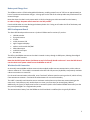
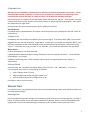
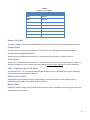
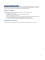
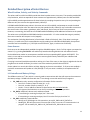
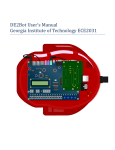
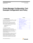
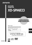
DE2Bot User’s Manual Georgia Institute of Technology ECE2031 Introduction This document is intended for the end-user of the DE2Bot: students in ECE2031. It provides an overview of the hardware, a walkthrough of the built-in self-test program, and a programming guide for use with the version of SCOMP provided during the final design project. Table of Contents DE2Bot Hardware Overview .......................................................................................................................................3 Feature Descriptions ..............................................................................................................................................4 Self-test Operation .....................................................................................................................................................6 Power-up Tests .......................................................................................................................................................6 Automated Self-test ...............................................................................................................................................6 Manual Tests ..........................................................................................................................................................7 Programming Guide ...................................................................................................................................................9 Changes to SCOMP .................................................................................................................................................9 SCOMP Interrupt System ........................................................................................................................................9 IO Device Quick Reference .................................................................................................................................. 10 Detailed Description of Select Devices ................................................................................................................ 11 Wheel Position, Velocity, and Velocity Commands......................................................................................... 11 Sonar Sensors .................................................................................................................................................. 11 I2C Controller and Battery Voltage .................................................................................................................. 11 Odometry ........................................................................................................................................................ 12 XIO ................................................................................................................................................................... 12 Good Practices for Robot Programming.............................................................................................................. 13 Appendix A: Example starting point for ASM code. ................................................................................................ 14 2 DE2Bot Hardware Overview The DE2Bot is comprised of the commercially-available AmigoBot with its electronics removed and replaced with custom hardware and an Altera DE2 FPGA development board. This configuration allows complete control of the robot hardware using custom digital circuits created within the FPGA. Locations of important features are shown below in Figure 1. Drive wheels with high-resolution encoders DE2 FPGA development board Power switch (under robot) Charging port (side of robot) Rear caster Sonar sensors Sonar sensors (total of 8 around (total of 8) robot) Status LEDs Interface board between DE2 and robot internals Figure 1. Locations of important DE2Bot features. 3 Feature Descriptions Wheels and Encoders The DE2Bot has two drive wheels, one on each side, allowing it to use differential steering to move around smooth or dense-carpeted surfaces. A rear caster wheel helps to support the robot without interfering with movement. The drive wheels are powered by DC motors through a reduction gearbox. Each motor is equipped with a high-resolution (39000 ticks per wheel revolution) quadrature encoder which can be used to keep track of wheel rotation and calculate angular position, velocity, and acceleration. The addition of specialized hardware can enable dead reckoning estimation of robot position. The control circuitry for the motors includes a watchdog timer that disables the motors if no ‘alive’ signal is received for approximately one second. In the default Quartus project for ECE2031, an additional safety mechanism disables the motors until SW17 has been toggled (both up and down) after power-up or reset. This is to ensure that the robot does not move immediately after being programmed, and guarantees that the robot will stop when PB0 is pressed. Sonar Distance Sensors The DE2Bot is equipped with eight sonar transducers that can be used to measure distances to objects. The sensors are arranged around the robot as shown in Figure 2 and numbered clockwise starting with Sonar 0, which is facing left (from the robots forward orientation; downwards in the figure). Figure 2. Sonar sensor numbering, positions, and directions. The sonar sensors can measure distances from 15cm up to 5m or more depending on the reflectivity of the object. The resolution of the measurement is dependent on the sampling speed of the interfacing hardware; the default resolution of the DE2Bot hardware is 1mm. Note that this does not imply 1mm accuracy, though within ±5mm can be expected. Each sonar sensor can be enabled independently. The sonar firing rate is 20Hz divided between all enabled sonars: if only one sonar is enabled, it is refreshed at 20Hz; if all eight sonars are enabled, the overall refresh rate is 2.5Hz (20Hz/8). 4 Battery and Charge Port The DE2Bot contains a 5.5Ah rechargeable LiPo battery, enabling several hours of ‘idle’ use or approximately an hour of continuous use between charges. A charge port on the side of the robot provides easy attachment of an external charger. Note that when the robot’s main power switch is ON, the charging port is disconnected from the battery. In order to charge, the power switch must be in the OFF position. Care should be taken to never discharge the battery below 13V. Doing so will reduce the life of the battery and may cause permanent damage. DE2 Development Board The Altera DE2 board provides access to a Cyclone II FPGA as well as various I/O, such as: 18 slide switches four push buttons 27 LEDs a 16x2-character LCD eight 7-segment displays audio in and out with ADC/DAC VGA video output an RS-232 serial port SD card slot. The DE2 on the DE2Bot connects to the robot’s internal circuitry through its GPIO ports, allowing direct digital control of all robot functions. Note that the DE2’s power button (red button at top left of board) should not be used. Leave the DE2 ON and use the robot’s main power switch to turn the DE2Bot on and off. Wireless Serial Connection An internally-mounted XBee wireless communication module enables remote communication, either robot-torobot or robot-to-PC. The module is connected to the DE2’s RS-232 port and, by default, transparently emulates a direct connection to a central PC. For the serial communication to be useful, some “back-end” software must be running on the PC, which will vary from semester to semester. Check with lab administrators for current functionality. The UART is internally rate-limited to ensure consistent results when many robots are communicating at the same time. Each robot may only send six bytes at a time, up to five times per second (every 200ms). Additionally, the [up to] six bytes must be sent in succession (within a few hundred SCOMP instructions) so that they can be packaged in to a single wireless packet. The communication latency from the DE2Bot to the PC and back is undefined, but is typically 50-100ms. 5 Self-test Operation On power-up, a self-test program is automatically loaded from non-volatile memory. This program enables the user to quickly test for proper operation of the DE2Bot hardware. Note: the self-test program uses PB0 as RESET. Press PB0 to restart the program at any time. Power-up Tests As soon as the DE2Bot is turned on (or when the self-test is restarted with PB0): The DE2Bot beeps for 0.2s The battery voltage is displayed (in hexadecimal) on the HEX5 and HEX4 seven-segment displays o Voltage is in tenths of volts. ‘A7’, 16.7V, is fully charged and ‘82’, 13.0V, is dead. The battery level is displayed as a bar graph on red LEDs 0-14 o A fully-charged battery will light all LEDs 0-14. A dead battery will light only LED 0. Green LEDs 0, 1, and 2 light, mirroring the inactive state of pushbuttons 1, 2, and 3 respectively o Pressing a PB will turn off the respective green LED. The LCD displays a menu prompting the user to choose “Self Test” or “Troubleshoot” Power-up Errors If the battery is too low to safely operate the DE2Bot, the user is warned with beeps, flashes, and a written warning on the LCD. In this case, turn off the DE2Bot immediately and plug it in to a charger. If nothing happens when the DE2Bot is turned on, there is likely a problem with the battery or power circuitry. Turn the DE2Bot switch to the OFF position and notify an administrator. Automated Self-test At the LCD prompt after power-up, pressing PB1 will begin a mostly-automated self-test routine. The LCD will provide prompts that allow the user to execute the automated self-test without this document, but detailed information is provided here for first-time users or in the case of errors. 1) Battery Check The battery voltage is tested and displayed in decimal on the LCD screen. Battery voltage should be 13-17V for proper robot operation. 2) Sonar Test Each of the eight sonar sensors is tested, starting with Sonar0 (left-facing sonar) and proceeding clockwise. Each sonar is polled until either a valid reading is obtained, or 5 seconds elapse. If the test pauses on a particular sonar, move an object (such as your hand) in front of that sonar so that a reading can be obtained. The current sonar is indicated on the red LEDs, or you can listen for the characteristic ‘clicking’ sound. Once all sonar sensors are tested and working, the message “All sonars are working” is displayed on the LCD, and the program automatically proceeds to the next test. Sonar Errors If a sonar does not return a valid reading within 5 seconds, it is assumed to be defective. At the end of the sonar test, the green LEDs display which sonar(s) are not working. Note the number(s), and return the DE2Bot to an administrator. 6 3) Encoder Test Warning: The test immediately following this test will cause the robot to move under its own power. Ensure that the DE2Bot is either on the floor in a clear area, or its wheels are raised off of the supporting surface. Continuing this test with the robot on a table can cause it to fall when the following test begins. Once the sonar test is complete, the LCD will display “Rotate left wheel 30+ degrees”. At this prompt, manually rotate the left wheel in either direction until the LCD changes to “Rotate right wheel 30+ degrees”, then repeat the rotation with the right wheel. During this test, the current encoder position value is displayed on HEX3-0. Encoder Errors If no wheel motion is detected within 10 seconds, the test fails and an error is displayed on the LCD. Inform an administrator. 4) Motor Test Immediately after the encoder test completes, the motor test begins. If the safety switch (SW17) has not been toggled since reset, the LCD will prompt “Toggle SW17”, at which point you should raise and lower SW17. Once the safety is disabled, the left wheel will begin turning forwards and the LCD will display “Left wheel turning? 2-N/1-Y”. If the wheel is turning, press PB1. If not, press PB2. The test will then repeat with the right wheel. Motor Errors If either wheel does not turn when expected: If LEDG8 (between HEX4 and HEX3) is flashing, the battery is too low to operate the motors. Turn the DE2Bot off and plug it in to a charger. If LEDG8 is not flashing, there is likely a problem with the motors or supporting electronics. Notify an administrator. Self-test Finish Once the motor test is complete, the LCD will display “Self Test Finish PB1 – Main Menu”. If any errors occurred during the self-test, a red LED will be lit as follows: LED0-7 indicate sonar 0-7 errors LED8 and LED9 indicate left and right encoder errors LED9 and LED10 indicate left and right motor errors Press PB1 to return to the main menu. Manual Tests From the main menu, pressing PB2 will enter manual-test (troubleshooting) mode, where specific hardware can be tested more thoroughly. Entering Tests Once in troubleshooting mode, raising a switch and pressing PB1 will enter the corresponding test - see Table 1 below. If multiple switches are up, the lowest-indexed test is selected. While in a test, pressing PB2 and PB3 together will return to the troubleshooting test selection mode. Use PB0 to return to the main menu. 7 Switch Raised TABLE 1 MANUAL TEST SELECTION Hardware Tested SW0 Battery SW1 Speaker SW2 Switches and Pushbuttons SW3 Sonars SW4 LEDs, 7-segment displays, LCD SW5 Wheel encoders SW6 Motors Battery Test (SW0) The battery voltage is continuously read and displayed on the LCD (in decimal) and 7-segment display (in hex). Speaker (SW1) The robot emits a stream of beeps with 0.15s on and 0.5s off. The LEDs light when the beep should be on. Switches and Pushbuttons (SW2) Switches 0-16 are reflected on red LEDs 0-16. The pushbuttons are reflected on the green LEDs 0-2. Sonars (SW3) Switches 0-7 will individually enable sonars 0-7. The value returned by the sonar is displayed on the 7-segment display in hexadecimal. If more than one sonar is enabled, only the lowest-indexed one’s value is displayed. LEDs, 7-segment displays, LCD (SW4) All LEDs flash at 1Hz. The 7-segment displays alternate between 0x1111 and 0xEEEE (exercising all segments). The LCD alternates between blank and black. Wheel Encoders (SW5) SW0 up/down selects between the left and right wheels. The selected wheel’s current position value is displayed on HEX3-0 and the immediate velocity on HEX7-4. Motors (SW6) Hold PB1 to power the right motor and PB2 to power the left motor. Raise SW0 to reverse the right motor, and SW1 to reverse the left motor. 8 Programming Guide At the beginning of the final project in ECE2031, students are provided with a Quartus project containing the SCOMP processor and many IO devices which interface with the DE2 and DE2Bot hardware. Each of these devices is assigned an IO address in the SCOMP system as detailed in Table 2. Changes to SCOMP SCOMP and its Quartus project have been modified from lab 8 in the following ways: SCOMP clocked at 12.5MHz. All SCOMP instructions in Table 7.1 of the lab manual implemented. Subroutine stack depth increased to 6. SHIFT instruction changed from “logical” to “arithmetic” to better support mathematical operations. Central IO_DECODER device replaces AND/NAND decoders for each peripheral. IO_CYCLE and IO_WRITE operation slightly modified to avoid possible contentions. SCOMP Interrupt System An interrupt system is being developed for SCOMP. Details will be added here when it is complete. 9 IO Device Quick Reference Name IO Address TABLE 2 SCOMP QUARTUS PROJECT I/O DEVICE DESCRIPTIONS IN/OUT Description SWITCHES 0x00 IN Read DE2 switches SW15-S0. LEDS 0x01 OUT Write to DE2 LEDs LEDR15-LEDR0. TIMER 0x02 IN/OUT Read 10Hz timer count. Write anything to reset to 0. XIO* 0x03 IN Read PB3-PB1, SW16, SAFETY signal, and some GPIO. SSEG1 0x04 OUT Write to left 4-digit seven-segment display. SSEG2 0x05 OUT Write to right 4-digit seven-segment display. LCD 0x06 OUT Write to LCD (16-bit hexadecimal). XLEDS 0x07 OUT Write to DE2 LEDs LEDG7-LEDG0 and LEDR17/LEDR16 BEEP 0x0A OUT Write 1-7 for beep frequency (360Hz*N). Write 0 to turn off beep. LPOS* 0x80 IN Read the current position of the left wheel encoder; 1.05mm/tick. LVEL* 0x82 IN Read the current velocity of the left wheel; 1.05mm/s. LVELCMD* 0x83 OUT Write the desired velocity of the left wheel; 1.05mm/s. RPOS* 0x88 IN Read the current position of the right wheel encoder; 1.05mm/tick. RVEL* 0x8A IN Read the current velocity of the right wheel; 1.05mm/s. RVELCMD* 0x8B OUT Write the desired velocity of the right wheel; 1.05mm/s. I2C_CMD* 0x90 OUT Write configuration information to the I2C controller. I2C_DATA* 0x91 IN/OUT Read or write data from/to the I2C controller. I2C_RDY* 0x92 IN/OUT Begin I2C transaction or check transaction status. UART_DAT 0x98 IN/OUT Read or write one byte (low-byte of AC) from/to the UART. UART_RDY 0x99 IN Read the status of the UART controller. DIST0 - DIST7* 0xA8 - 0xAF IN Read the measured distance from Sonar0 - Sonar7. SONAREN* 0xB2 OUT Write bits 0-7 to enable Sonar0 - Sonar7. XPOS* 0xC0 IN Read dead-reckoning X position estimation; 1.05mm/count. YPOS* 0xC1 IN Read dead-reckoning Y position estimation; 1.05mm/count. THETA* 0xC2 IN Read dead-reckoning angle estimation; 702 counts/circle. RESETODO 0xC3 OUT Reset dead-reckoning odometer: X,Y,θ = 0,0,0. * additional details in following sections 10 Detailed Description of Select Devices Wheel Position, Velocity, and Velocity Commands The values read from LPOS and RPOS provide the wheel encoder counts since reset. The encoders provide 304 ticks/revolution, which corresponds to linear movement of approximately 1.05mm/count for LPOS and RPOS. LVEL and RVEL provide approximations of wheel velocity by sampling the position every 0.1s and providing the difference x10; the units are thus approximately 1.05mm/s. LVELCMD and RVELCMD accept values in the same units as LVEL and RVEL, and attempt to control the wheel velocities to match that value. Be aware that very low speeds (usually <50mm/s) may not be able to overcome the static friction of the motors, gearboxes, axles, and wheels, and so may not result in any movement. However, once moving, the lower bits of LVELCMD and RVELCMD do provide additional resolution to the speed. The values sent to LVELCMD and RVELCMD should not exceed ±511. If a value outside that range is provided, the motor controller will interpret it as 0 (stopped). The acceleration (including deceleration) of each wheel is fixed at 512units/s; thus, if the robot is moving at velocity (in robot units) and is commanded to stop (by sending 0 to LVELCMD and RVELCMD), the expected overshoot can be estimated by (the result of which is, again, in robot units of 1.05mm). Sonar Sensors Each sonar can be independently enabled through the SONAREN register. Bits 0-7 of this register correspond to sonars 0-7; e.g. writing 0b00000001 will enable only Sonar0 and writing 0b11111111 will enable all sonars. Each enabled sonar makes its measurements available at the corresponding DIST register DIST0-DIST7. This value is in mm and has a resolution of 1mm, but its accuracy (both linearity and offset) are undefined and typically varies ±5mm. If no ping is returned (usually because either nothing is in front of the sonar, or the object is angled such that the ping bounces in another direction), the value is set to the maximum positive value of 0x7FFF. Sonars update in a round-robin fashion at 20Hz, skipping any that are not enabled. If all sonars are enabled, a particular measurement will update at 2.5Hz (20Hz/8). If only one sonar is enabled, it will update at the full 20Hz. I2C Controller and Battery Voltage The DE2Bot contains an I2C bus, which is currently used to communicate with the A/D converter that measures the battery voltage. SCOMP interfaces with the I2C bus through a controller with three I/O registers: I2C_CMD: write-only; contains configuration information for the controller. o bits 15-12: number of bytes to write (0, 1, or 2) o bits 11-9: number of bytes to read (0, 1, or 2) o bits 8-1: 7-bit I2C address of device to communicate with; excludes RnW bit o bit 0: ignored; the RnW bit is set on the fly according to the current operation I2C_DATA: read/write; data to send, and data received. o If transmitting or receiving one byte, bits 7-0 are used o If transmitting or receiving two bytes, bits 15-9 are the first byte, then bits 7-0 I2C_RDY: read/write; status indicator o Writing to I2C_RDY begins an I2C transaction; set up I2C_CMD and I2C_DATA first. o Reading I2C_RDY will return zero if the controller is idle, or non-zero if a communication is in progress. Do not modify I2C_CMD or I2C_DATA while I2C_RDY reads as non-zero. 11 Odometry The Quartus DE2Bot project contains a device that performs dead-reckoning odometry: continuously integrating the movement of the wheels to maintain an estimate of the robot’s position and heading. This estimation can be read from IO registers XPOS, YPOS, and THETA. At power-up or reset, the position of the robot defaults to X,Y,θ=0,0,0. The coordinate system is shown in Figure 3: the reset orientation is defined as facing the positive X direction, with positive Y to the left, and theta following the normal right-handed convention (with Z upwards). Writing to IO location RESETODO will reset the odometry to this position. Figure 3. Coordinate system used for DE2Bot odometry. The units for the X and Y positions are 1.05mm/count – the same as the resolution of LPOS and RPOS. For theta, one full rotation of the robot is divided in to 702 units (a product of the robot geometry), giving an approximate resolution of 0.51°/count. The theta value will always be [0,701]; rotating counterclockwise past 701 will rollover to 0, and rotating clockwise past 0 will rollover to 701. Dead-reckoning is highly susceptible to accumulated error from wheel slippage, wheel-size and wheel-base errors, mathematical rounding, and other sources. The odometry values will likely contain significant error after as little as a few meters of travel or one rotation of the robot, and much of the error will not be systematic. XIO The value read from XIO contains the following signals: XIO[15..5] : GPIO pins on the DE2 header XIO[4] : SAFETY signal, which indicates whether or not SW17 has been toggled XIO[3] : SW16 XIO[2..0] : Pushbuttons PB3– PB1 (PB0 is global reset and cannot be read) Note that the pushbuttons are active-low: a pressed pushbutton will appear as a ‘0’ in XIO. 12 Good Practices for Robot Programming This section details some recommended practices for safe and effective use and control of the DE2Bot. At Program Start As soon as the program starts or is reset, the following should be done in order: 1. 2. 3. 4. Immediately stop the robot by writing 0 to LVELCMD and RVELCMD Check the battery voltage, and prevent execution if it is below 13V Wait for the safety switch (SW17) to be toggled Wait for some form of user input (e.g. pressing a PB) An example of this initialization procedure can be found in Appendix A. Testing Values Two points must be kept in mind when making decisions based on values obtained from LPOS/RPOS, odometry, sonars, or any other real-world measurement: Never test for exact values, as there is no guarantee that a particular value will occur. Instead, always test for a range. o Example1: polling LPOS while the robot is moving might return 0xFE at one sample and 0x100 at the next sample, so testing for 0xFF will never pass. Testing for ≥0xFF would correctly trigger even if 0xFF itself never occurs. o Example2: many values are impossible to obtain from peripherals because of limited range or resolution. For example, LVEL and RVEL only have a resolution of 10 units. Be aware of edge conditions, which can erroneously cause tests to pass or fail. o Example 1: if the robot is facing its reset direction then ideally theta would be 0, but any small turn clockwise will change theta to 701, in which case a test for theta>100 (intended to check if the robot has turned a certain amount) will immediately pass. 13 Appendix A: Example starting point for ASM code. ; ; ; ; ; SimpleRobotProgram.asm Created by Kevin Johnson (no copyright applied; edit freely, no attribution necessary) This program does basic initialization of the DE2Bot and provides an example of some peripherals. ; Section labels are for clarity only. ORG &H000 ;Begin program at x000 ;*************************************************************** ;* Initialization ;*************************************************************** Init: ; Always a good idea to make sure the robot ; stops in the event of a reset. LOAD Zero OUT LVELCMD ; Stop motors OUT RVELCMD OUT SONAREN ; Disable sonar (optional) CALL CALL OUT SetupI2C BattCheck LCD ; Configure the I2C to read the battery voltage ; Get battery voltage (and end if too low). ; Display batt voltage on LCD WaitForSafety: ; Wait for safety switch to be toggled IN XIO ; XIO contains SAFETY signal AND Mask4 ; SAFETY signal is bit 4 JPOS WaitForUser ; If ready, jump to wait for PB3 IN TIMER ; We'll use the timer value to AND Mask1 ; blink LED17 as a reminder to toggle SW17 SHIFT 8 ; Shift over to LED17 OUT XLEDS ; LED17 blinks at 2.5Hz (10Hz/4) JUMP WaitForSafety WaitForUser: IN AND SHIFT STORE SHIFT OR OUT IN AND JPOS LOAD OUT ; TIMER Mask1 5 Temp 1 Temp XLEDS XIO Mask2 WaitForUser Zero XLEDS Wait for user to press PB3 ; We'll blink the LEDs above PB3 ; Both LEDG6 and LEDG7 ; (overkill, but looks nice) ; XIO contains KEYs ; KEY3 mask (KEY0 is reset and can't be read) ; not ready (KEYs are active-low, hence JPOS) ; clear LEDs ;*************************************************************** ;* Main code ;*************************************************************** Main: ; "Real" program starts here. OUT RESETODO ; reset odometry in case wheels moved after programming JUMP Main ; this example does nothing. Die: ; Sometimes it's useful to permanently to stop execution. ; This will also catch the execution if it accidentally ; falls through from above. LOAD Zero ; stop everything OUT LVELCMD OUT RVELCMD OUT SONAREN IN TIMER OUT SSEG2 ; an indication that we are dead JUMP Die ; do this forever ;*************************************************************** ;* Subroutines ;*************************************************************** ; Subroutine Wait1: OUT Wloop: IN OUT ADDI JNEG RETURN to wait (block) for 1 second TIMER TIMER XLEDS -10 Wloop ; user-feedback that a pause is occuring ; 1 second in 10Hz ; This subroutine will get the battery voltage, ; and stop program execution if it is too low. ; SetupI2C must be executed prior to this. BattCheck: CALL GetBattLvl JZERO BattCheck ; A/D hasn't had time to initialize SUB MinBatt JNEG DeadBatt ADD MinBatt ; get original value back RETURN ; If the battery is too low, we want to make ; sure that the user realizes it... DeadBatt: LOAD Four OUT BEEP ; start beep sound CALL GetBattLvl ; get the battery level OUT SSEG1 ; display it everywhere OUT SSEG2 OUT LCD LOAD Zero ADDI -1 ; 0xFFFF OUT LEDS ; all LEDs on OUT XLEDS CALL Wait1 ; 1 second Load Zero OUT BEEP ; stop beeping LOAD Zero OUT LEDS ; LEDs off OUT XLEDS CALL Wait1 ; 1 second JUMP DeadBatt ; repeat forever ; Subroutine to read the A/D (battery voltage) ; Assumes that SetupI2C has been run GetBattLvl: LOAD OUT OUT CALL IN RETURN ; Subroutine ; Only needs SetupI2C: CALL LOAD OUT LOAD OUT OUT CALL RETURN I2CRCmd I2C_CMD I2C_RDY BlockI2C I2C_DATA ; ; ; ; ; 0x0190 (write 0B, read 1B, addr 0x90) to I2C_CMD start the communication wait for it to finish get the returned data to configure the I2C for reading batt voltage to be done once after each reset. BlockI2C I2CWCmd I2C_CMD Zero I2C_DATA I2C_RDY BlockI2C ; ; ; ; ; ; ; wait for idle 0x1190 (write 1B, read 1B, addr 0x90) to I2C_CMD register 0x0000 (A/D port 0, no increment) to I2C_DATA register start the communication wait for it to finish ; Subroutine to block until I2C device is idle BlockI2C: IN I2C_RDY; ; Read busy signal JPOS BlockI2C ; If not 0, try again RETURN ; Else return ;*************************************************************** ;* Variables ;*************************************************************** Temp: DW 0 ; "Temp" is not a great name, but can be useful ;*************************************************************** ;* Constants ;* (though there is nothing stopping you from writing to these) ;*************************************************************** NegOne: DW -1 Zero: DW 0 One: DW 1 Two: DW 2 Three: DW 3 Four: DW 4 Five: DW 5 Six: DW 6 Seven: DW 7 Eight: DW 8 Nine: DW 9 Ten: DW 10 ; Some bit masks. ; Masks of multiple bits can be constructed by ORing these ; 1-bit masks together. Mask0: DW &B00000001 Mask1: DW &B00000010 Mask2: DW &B00000100 Mask3: DW &B00001000 Mask4: DW &B00010000 Mask5: DW &B00100000 Mask6: DW &B01000000 Mask7: DW &B10000000 LowByte: LowNibl: DW &HFF DW &HF ; binary 00000000 1111111 ; 0000 0000 0000 1111 ; some useful movement OneMeter: DW 952 HalfMeter: DW 476 TwoFeet: DW 640 Deg90: DW 176 Deg180: DW 351 Deg270: DW 527 Deg360: DW 702 FSlow: DW 100 RSlow: DW -100 FMid: DW 350 RMid: DW -350 FFast: DW 500 RFast: DW -500 values ; ~1m in 1.05mm units ; ~0.5m in 1.05mm units ; ~2ft in 1.05mm units ; ~90 degrees in odometry units ; 180 ; 270 ; can never actually happen; for math only ; 100 is about the lowest velocity value that will move MinBatt: I2CWCmd: I2CRCmd: ; 13.0V - minimum safe battery voltage ; write one i2c byte, read one byte, addr 0x90 ; write nothing, read one byte, addr 0x90 DW 130 DW &H1190 DW &H0190 ; 350 is a medium speed ; 500 is almost max speed (511 is max) ;*************************************************************** ;* IO address space map ;*************************************************************** SWITCHES: EQU &H00 ; slide switches LEDS: EQU &H01 ; red LEDs TIMER: EQU &H02 ; timer, usually running at 10 Hz XIO: EQU &H03 ; pushbuttons and some misc. inputs SSEG1: EQU &H04 ; seven-segment display (4-digits only) SSEG2: EQU &H05 ; seven-segment display (4-digits only) LCD: EQU &H06 ; primitive 4-digit LCD display XLEDS: EQU &H07 ; Green LEDs (and Red LED16+17) BEEP: EQU &H0A ; Control the beep LPOS: EQU &H80 ; left wheel encoder position (read only) LVEL: EQU &H82 ; current left wheel velocity (read only) LVELCMD: EQU &H83 ; left wheel velocity command (write only) RPOS: EQU &H88 ; same values for right wheel... RVEL: EQU &H8A ; ... RVELCMD: EQU &H8B ; ... I2C_CMD: EQU &H90 ; I2C module's CMD register, I2C_DATA: EQU &H91 ; ... DATA register, I2C_RDY: EQU &H92 ; ... and BUSY register UART_DAT: EQU &H98 ; UART data UART_RDY: EQU &H98 ; UART status SONAR: EQU &HA0 ; base address for more than 16 registers.... DIST0: EQU &HA8 ; the eight sonar distance readings DIST1: EQU &HA9 ; ... DIST2: EQU &HAA ; ... DIST3: EQU &HAB ; ... DIST4: EQU &HAC ; ... DIST5: EQU &HAD ; ... DIST6: EQU &HAE ; ... DIST7: EQU &HAF ; ... SONAREN: EQU &HB2 ; register to control which sonars are enabled XPOS: EQU &HC0 ; Current X-position (read only) YPOS: EQU &HC1 ; Y-position THETA: EQU &HC2 ; Current rotational position of robot (0-701) RESETODO: EQU &HC3 ; write anything here to reset odometry to 0