1
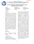
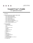
Using the Multi-Layer Model for
Building Interactive Graphical Applications
Jean-Daniel Fekete and Michel
Beaudouin-Lafon
Laboratoire de Recherche en
Informatique, CNRS URA 410
Bâtiment 490, Université de Paris-Sud
91405 ORSAY Cedex, FRANCE
+33-1-69-41-63-97
[email protected]
as Xlib to program direct manipulation techniques adapted to
the domain covered by the editor. This situation results in
very high costs for the design, implementation and maintenance of interactive graphical applications.
ABSTRACT
Most interactive graphical applications that use direct manipulation are built with low-level libraries such as Xlib because
the graphic and interaction models of higher-level toolkits
such as Motif are not extensible. This results in high design, development and maintenance costs and encourages the
development of stereotyped applications based on buttons,
menus and dialogue boxes instead of direct manipulation of
the applications objects.
There have been several attempts to provide high level tools
for building such applications, including popular toolkits
such as Garnet [26], Unidraw [33], Fresco [21, 32] and OpenInventor [28]. Unfortunately, these tools are not adapted to
the development of sophisticated graphical editors because of
their lack of extensibility:
In this article we argue that these drawbacks come from the
fact that high-level toolkits rely on a visualization model to
manage interaction. We introduce a model that uses several
graphical layers to separate the graphic entities involved in
visualization from those involved in feedback and interaction
management. We describe the implementation of this MultiLayer Model and we show how it can take advantage of software and hardware graphic extensions to provide good performance. We also show how it supports multiple input devices and simplifies the description of a wide variety of interaction styles. Finally, we describe our experience in using
this model to implement a set of editors for a professional animation system.
their graphic models and understanding of hardware features are predefined, and
they impose a fixed set of mechanisms to manage interaction.
Most graphic platforms can use different graphic models. For
example, both X [30] and Microsoft Windows [23] support
the OpenGL extension [27] for enhanced 2D and 3D graphics. X has several other extensions such as the X Image Extension [29] for pixel image manipulation and PEX [24] to
support the PHIGS graphic model. These extensions are motivated by the availability of accelerated graphic boards that
also provide features such as overlay windows or real-time
image compression and decompression. Unfortunately, these
extensions are not used by high-level toolkits such as those
cited above.
KEYWORDS: toolkits, multi-layer model, graphic model,
interaction, optimizations.
1 INTRODUCTION
In addition, only the two standard input devices are supported
by these toolkits: one mouse and one keyboard. The management of interaction is based on the Garnet Interactors model
[25] or on Manipulators [33]. Interactors implement the automaton that describes the interaction styles while manipulators also provide graphical feedback during the manipulation.
For interfaces based on a single mouse and keyboard, a small
set of interactors/manipulators can implement most interaction styles. But with more input devices, the number of interaction styles becomes too large to be pre-programmed in the
toolkit and application developers have to build their own manipulators, usually from scratch and using low-level mechanisms.
A wide variety of graphical editors are available nowadays
for domains such as image correction and enhancement,
schematic and illustrative drawing, and more recently 3D
drawing and video editing. Despite the fact that they use similar direct manipulation techniques such as selection and dragging, these editors are usually developed from scratch with
low-level toolkits. Popular high-level toolkits such as Motif
require the developers to resort to lower level libraries such
These limitations on both the graphic model and the interac1
Schematic
Realistic
Pixel
Paint
Retouch
Text
TextEdit
WYSIWYG
2D Vector
Draw
Illustration
3D
CAD
Realistic
frame drawing of 3D scenes, also used by 2D illustration editors such as Adobe Illustrator [2]. Most WYSIWYG text editors also provide a relaxed model where page-level layout is
not displayed to speed up the redisplay and to avoid distracting the typist at column or page boundaries.
Table 1: Classification of common graphic models.
bold is used when a model can be implemented on a
conventional window system. bold italic is used when
a relaxed version of a model can be implemented on a
conventional window system.
Relaxed models are mainly used for performance reasons. A
realistic 3D scene can be very expensive to compute whereas
a wire-frame view is much cheaper and is sufficient for many
editing operations. Relaxed models are common in interactive graphical applications. For example, an object being interactively dragged is usually displayed with a relaxed model
that only displays its outline. In this case, the relaxed model
is used to reduce the response time and to avoid cluttering.
tion model result in the following situation: either the application is build with a high-level toolkit and its interface makes
a poor use of direct manipulation techniques and hardware
features (input devices and graphics hardware), or the application is build with a low-level toolkit and it is more efficient
and usable but much more expensive to develop and maintain.
2.2
We believe that this situation comes from the fact that highlevel toolkits rely on an output-oriented visualization model,
described in textbooks such as [13], to manage interaction.
Instead, we propose to use several superimposed graphical
layers to separate the entities involved in visualization from
those involved in interaction management and feedback.
For interactive applications, the graphic structure also implements the pick operation which finds the node or set of nodes
that intercept a given position. The position usually comes
from an event sent by a positional input device such as the
mouse. The resulting node or set of nodes can be used as the
target of a structural operation such as changing the color or
starting a direct manipulation.
This Multi-Layer Model was first introduced in [10]. In this
article, we focus on the description of the model and its implementation, and on our experience in using the model to
develop several graphical editors in the TicTacToon system
for Professional 2D Animation [11]. Before presenting the
model itself, we introduce the standard visualization model
and some existing high-level toolkits.
2.3
Virtual Surface
The virtual suface needs to be redisplayed when a previously invisible part becomes visible, and when its contents
has changed. All the high-level toolkits implement a deferred
redisplay mechanism. The area of the virtual surface known
to be out of date is added to the damaged region. At a later
time, usually when the application is idle, the toolkit triggers
a redisplay that traverses the graphic structure and only redraws graphic objects intersecting the damaged region. The
damaged region is then reset.
2 STANDARD VISUALIZATION MODEL
The standard visualization model defines three components:
A Canvas, or virtual graphic surface (virtual surface for
short), is a data structure that stores an image as a 2D array of pixels. It also stores control information about the
size, position, visibility and attributes of the image1 .
A Graphic Model is the set of functions and graphic attributes used to access and modify the contents of the virtual surface.
A Graphic Structure is a data structure that holds the information required to display an image defined with the
graphic model onto the virtual surface.
2.4
Problems
This visualization model works well for applications that display only one graphic structure. But for interactive applications, specific objects need to be displayed in addition to the
main graphic structure in order to support interaction. For example, when selecting an object in a 2D editor, graphic objects called handles appear, that the user can grab to start a
manipulation. These handles do not belong to the main structure and can be described with a very simple graphic model.
Similarly, when dragging an object, most programs display
an outline of the graphic object being manipulated. Again,
this outline object does not belong to the main structure and
can be displayed with a much simpler graphic model than that
of the main structure.
2.1 Graphic Models
The graphic models used by most interactive applications are
summarized in table 1. We distinguish schematic models
(first line) from realistic models (second line) based on the
number of available graphic attributes and the complexity of
a typical image. The colums represent the types of objects
represented by the models. The table also shows that current
window systems are mainly designed for schematic models.
We also introduce the notion of relaxed model: A virtual surface implements a relaxed graphic model when some of the
primitives or attributes of the model are ignored or simplified
during image rendering. A popular relaxed model is the wire1 This
Graphic Structure
The graphic structure is usually a tree or a direct acyclic graph
(DAG) of graphic objects. Drawing the structure consists of
a preorder traversal of the tree where each node is requested
to display its contents on a virtual surface according to the
graphic model. Each node can define its own graphic attributes. Other graphic attributes are maintained during the
traversal.
New types of interactive applications introduce even more
such objects. For example, groupware editors such as
GroupDesign [5] use specific graphic entities to display the
activity of other participants working on the same document.
definition is inspired by Foley et al. [13, page 53]
2
Toolkit
Unidraw
Garnet
Graphic
Structure
Tree
Fresco
DAG
OpenInventor
DAG
Graphic
Model
2D structured
resolution
dependent
2D structured
resolution
independent
2D and 3D
Domain
Unidraw, the first step is implemented by a Tool object, which
takes a starting event and returns a Manipulator. This manipulator then grabs all the input events during the direct manipulation and provides graphical feedback. When the manipulation is over, it returns a Command object that is executed. In
OpenInventor, some nodes of the DAG (called Manipulators)
start a manipulation when they receive a specific event. Like
Unidraw, manipulators grab all the events until the end of the
manipulation. The result of the manipulation is a modification of the DAG. The toolkits also manage a Selection, which
is a list of objects associated with some graphical feedback.
2D
schematic
2D
schematic
schematic
and realistic
Table 2: Comparison of high-level toolkits
Apart from the main graphic structure, various graphic objects are used to display the selection and the manipulation
feedback. Unidraw hides these objects from the application
programmer whereas OpenInventor inserts them in the main
graphic structure. Fresco Pacers are also nodes of the main
graphic structure. During direct manipulation, either the
main graphic structure is incrementally modified (in OpenInventor and Fresco) or simple objects are directly displayed
with little or no control over their shape and graphic attributes
by the application programmer.
Another example is the ink used in pen-based interface to
display a stroke before it is interpreted by the system. Window systems provide ad-hoc solutions for managing special
graphic entities such as background images and the mouse
cursor. But they are no longer sufficient for sophisticated applications. For example, the visual feedback of a 3D mouse
requires a 3D graphic object that cannot be represented by a
window system cursor; when using multiple positional input
devices (e.g. a mouse and a tablet), the window system can
only display one cursor.
We believe that these mechanisms are inadequate for the following reasons:
selection feedback and manipulation feedback do not belong to the main graphic structure; they need a different
graphic model, usually a relaxed one, and they should not
interfere with structural operations on the main graphic
structure.
Specific graphic entities may need to be managed when
editing a graphic structure. Hidden mechanisms are not
sufficient to manage all the graphic entities that a domain
may require. For example, a graphical editor turned into a
groupware application will require additional graphical objects for awareness of other participants (e.g., telepointers).
Optimizations are difficult to implement; OpenInventor advises the application programmer to use overlay planes
when they exist and Fresco proposes to use Pacers to get
smoother feedback. Such optimizations rely on specific
hardware or characteristics of a typical scene and are difficult to program in a generic, portable way.
3 CURRENT HIGH-LEVEL TOOLKITS
High-level toolkits such as Unidraw, Fresco and OpenInventor are based on the visualization model described above. Table 2 summarizes the graphic models and graphic structures
that they use.
Unidraw [33] requires the application programmer to describe the graphic structure as a tree and offers several mechanisms to edit it. Internally, Unidraw manages several other
graphic structure that are hidden from the application programmer. For example, each view manages a page layer and
a grid layer, but there is no support to change their standard
behavior.
Fresco defines a clean and efficient mechanism to manage a
DAG of graphic objects. In order to optimize redisplay during direct manipulation, the authors of Fresco have proposed
to use special objects called Pacers [31]. Pacers can provide
a smoother feedback by relaxing the quality of their graphic
display during direct manipulation. However, redisplaying
a scene still involves redisplaying all the objects intersecting the damaged region, not only the objects being manipulated. This optimization is therefore insufficient when a scene
is complex.
4
THE MULTI-LAYER MODEL
We have designed the Multi-Layer Model [10] to solve these
problems. This model uses a separate graphic layer for each
specific graphic structure or graphic model involved in the interaction. The layers are stacked (composed one on top of the
other) and the appearance of the stack is maintained by a layer
stack object. Interaction is managed by layer tool objects.
OpenInventor is mainly oriented towards 3D graphics. The
graphic structure is a DAG that ca be edited. Redisplay is
triggered by any modification of the structure. The graphic
model is based on OpenGL, which is designed to take advantage of any available graphic accelerator. However, the redisplay time is still a function of the complexity of a scene.
As an example, consider the main window of the graphical
editor in figure 1. We can decompose its contents into six
different layers: the background, the grid, the main graphic
structure, the selection handles, the direct manipulation feedback and the cursor. When interacting with this window, new
graphic entities appear such as a selection rectangle being
dragged. With the multi-layer model, each of these graphic
entities belong to a separate layer. We have found that most
graphical editors can be described with the following layers
(this list is not limitative and is not built into the model):
3.1 Interaction
The above high-level toolkits decompose a direct manipulation in three steps: finding a handler for a starting event,
handling the direct manipulation of graphic objects, and executing a command upon reception of the ending event. In
3
ers described by only one point (the position of a cursor for
example) to very complex layers maintaining a 3D structure
with complex graphic primitives and hundreds of graphic attributes.
4.2
Layer Stack
The layer stack (or simply stack) is a list of layers, their associated layer tools and a virtual surface. It has two roles:
maintaining the graphical appearance of superimposed layers
on its virtual surface and dispatching events to the first layer
tool that accepts to handle it.
When the contents of a layer changes, or when a layer is
added or removed, the stack redisplays the contents of the virtual surface. The simplest strategy is to ask each layer, from
back to front, to redisplay its contents. We describe in section 6 some strategies to avoid expensive redisplays. During development, a simple strategy can be implemented first,
and optimized at a later time. Several strategies can be implemented and selected at run-time according to the resources
available (e.g. graphics accelerator).
Figure 1: Graphic entities appearing in a 2D editor
Background: this layer displays an almost constant image
for decorative purposes.
Grid: this layer displays a grid used to constrain the position and size of objects. Sometimes, it displays more sophisticated objects such as drawing models. The displayed
objects sometimes attract positional input devices in order
to enforce the constraints on object positions or sizes.
Main: this layer displays the main graphic structure, i.e.
the objects that the user wants to interact with.
Selection: this layer displays graphic entities (e.g., handles) to show that a graphic object in the main layer is selected.
Direct Manipulation: during direct manipulation of objects, this layer displays a shape (e.g. a rectangle or outline)
showing that a graphic object of the main layer is being manipulated.
Lasso or Rectangle: during lasso or rectangle selection,
this layer displays a simple shape specifying a region of the
main layer.
Cursor: this layer displays a graphic object showing the
position of active positional input devices.
For handling interaction, the stack uses the following algorithm: when an event is received by the stack, each layer tool
is asked, from front to top, whether it wants to handle it. The
first layer tool that accepts the event stops it from propagating
to lower layers.
4.3
Layer Tool
A layer tool (or simply tool) is responsible for deciding
whether a layer intercepts an event and, if so, for handling
it. Each tool is associated with one layer and can access it
to make its decision, for example by invoking its pick operation. Some tools may decide to handle events depending on
their type or on some internal state, or to never handle any
event. For example, the tool associated with a cursor layer is
usually insensitive to all events.
With the dispatch mechanism used by the stack, a layer and its
associated tool can filter any event from the layers below it.
For example, a pen-based interface is likely to use a Stroke
layer to display the electronic ink left by the pen. In order
to implement gesture recognition, the associated layer tool
will intercept the pen up, down and move events and interpret them. These events will never reach the lower layers.
The main advantages of this model are the separation of visualization from interaction, the reusability of application components (layers and layer tools), and the possibilityto develop
the application incrementally.
5
MULTIPLE GRAPHIC MODELS
The stack composes the contents of each layer to make it appear in a window. Therefore, the graphic model of the virtual surface of the stack is defined by the window system (or
derived from it). An important property of the Multi-Layer
Model is to let each layer use the graphic model it needs. The
stack is responsible for optimizing the resources according
to the demand of the graphic models of the layers. Here are
some examples:
4.1 Layer
A layer has two roles: it keeps the display of a graphic structure on a virtual surface up to date and it computes the list of
graphic objects picked by a positional input device.
The graphic model of the virtual surface and the nature of
the graphic structure can vary widely from one layer to another. On a popular program like MacDraw [8], the main
layer manages a tree structure where each leaf is a graphic
primitive with its attributes and where each node is a group.
The graphic model is 2D vector-based with around 20 graphic
attributes. In contrast, a layer managing the selection rectangle has a very simple graphic structure: a rectangle. Its
graphic model only requires lines with a width of one pixel.
A wide range of graphic models can be used, from simple lay-
Background: since the background almost never changes,
it should be kept in an off-screen image if it is long to redisplay. Some window systems, e.g. X, can manage the background directly.
Grid, Lasso and Rectangle: these layers usually display
one-pixel thin lines in black and can use a relaxed graphic
model.
4
Selection: most 2D editors use one or two colors for selection feedback with simple outlines or rectangles (handles).
Even in 3D, the graphic model used for the selection is usually relaxed (wire-frame).
Direct Manipulation: most 2D editors use a relaxed mode
for the feedback of objects being manipulated. Some editors use the same model as the main layer’s model.
Cursor: the cursor layer usually displays small images using few colors. All window systems can manage one cursor.
5.3
Software Rendering
When no appropriate extension is available to translate a
graphic model, the only solution is to use software rendering.
The graphic primitives and graphic attributes are interpreted
to update a 2D image which is composed onto the stack virtual surface. Performance depends both on the graphic model
and on the mechanism to transfer an image from user memory
to screen memory.
5.4
Implementation of a Graphic Model
By encapsulating the graphic model into an object, each application can specialize a layer’s graphic model according to
several criteria, such as the graphic properties of the layer’s
content, the graphic resources available at run-time, or specific design choices.
We now describe three mechanisms to compose the virtual
surface of the layer onto the virtual surface of the stack:
translation, use of extensions and software rendering. These
mechanisms convert the layer’s graphic model into a model
compatible with the window system’s graphic model.
For example, in the FontStudio vector-based font editor [20],
the main layer displays the character outlines in black. The
selection layer can therefore use any other color (FontStudio
uses pink). In contrast, a paint program such as Adobe PhotoShop [3] cannot ensure that a specific color will always be
distinguishable from the main layer’s contents. Thus, Photoshop displays the selection with animated dashed lines. In a
multi-layer implementation of these editors, the same selection layer could be used for both editors but the stack would
choose a different object for the translation.
5.1 Translation
The graphic model used by a layer can be simpler than or
equivalent to the stack’s graphic model. In this case, the stack
can provide the layer with an object that translates all the
function calls required by the layer’s graphic model into function calls understood by the stack’s graphic model. The most
frequent case of translation is simply the identity, when the
graphic model of the stack is a superset of the layer’s model.
Another frequent case is the translation from a relaxed model
into the stack model. For example, the grid layer, the selection layer, the direct manipulation layer and the lasso layer
only draw thin lines with a single color. It is easy to translate this graphic model into the stack graphic model, since the
only requirement it that the lines should be visible. The translation mechanism can choose any color and drawing mode
that fit this requirement. Often, the color will be black and
the mode will be XOR.
6
OPTIMIZING REDISPLAY
When a region of a layer is damaged, the stack needs to redisplay the correponding region of its virtual surface. The simplest method is to ask each layer, from back to front, to redisplay its content and compose it onto the virtual surface. Several optimizations can be implemented by the stack to avoid
expensive partial redisplays of undamaged layers. These optimizations depend on the nature of each particular layer and
also on the layout of the stack. For example, if a cursor layer
is always on top of the stack, saving the contents of the virtual layer under each cursor enables the stack to quickly erase
cursors when they move (this is how most window systems
implement the cursor).
Translating a graphic model can also be used to relax a
graphic model on the fly. This is the case when a layer’s
model is complex and cannot be translated into the stack’s
model faithfully. The translation is used to simplify or ignore
some graphic attributes, which results in a relaxed graphic
model. This type of translation is also useful to achieve good
performance at the expense of graphic quality when no specialized hardware is available.
We use two methods to optimize redisplay in a stack:
a set of attributes associated with each layer that describe
the optimizations that are likely to be effective,
the specialization of the stack for each application.
With simple applications, the standard stack can use a reasonably efficient implementation by using the attributes. More
demanding graphical applications require the stack to be specialized. The redisplay attributes that we use include the following:
single color: this attribute informs the stack that only one
color is required by the layer. When the layer is on top (or
the layers above it are empty), the stack can use optimizations such as using an overlay plane if available, or one
plane in the color look-up table, or XOR mode when the
look-up table is correctly set up, etc.
transient: this attribute informs the stack that the contents
of the layer should be updated as fast as possible. It is
used for example for the direct manipulation layer and for
a stroke layer that displays the ink of a pen. When the layer
is on top and a graphic object appears on it, the stack caches
5.2 Use of Extensions
Some window systems have extensions that give access to a
larger range of graphic models. For example, OpenGL and
Display PostScript [4] are available for the X Window System
and can be used on any virtual surface (drawable) managed
by X, in combination with X’s native model. In this case,
a layer’s model can be translated into a graphic model supported by an extension.
However, some extensions cannot use virtual surfaces that are
also used by the native graphic model. For example, some
video boards can only display frames in shared memory. In
such cases, the layer’s image must be generated off-screen
and composed by the stack onto its virtual surface. With this
technique, it is still possible to use different graphic models
in a stack.
5
the mouse down event has reached the background layer, it
has not been intercepted by any other layer tool above it and
therefore the event occured outside any graphic object. The
external actions clear the selection and start the dragging of
a selecting rectangle in the rectangle layer. We can see in the
last line of the table that the rectangle layer only intercepts
events when started.
the image below it and ignores other layers’ redisplays until
all graphic objects have disappeared from the layer.
cache: this attribute informs the stack that the contents of
the layer should be cached because it is expensive to compute and does not change often. The stack layer allocates
an offscreen virtual surface with a mask or alpha channel
to store the contents of the layer. This offscreen virtual surface is used during a redisplay triggered by another layer.
animated: this attribute informs the stack that the contents
of the layer changes frequently. When such a layer is on
top, the stack saves the contents of the image under the
graphic objects. When it is not on top, the stack maintains
a mask of modified regions above it and a copy of the image below it. When the content is modified, the mask is
installed as a clip to protect pixels modified by the layers
above. The image below is then redisplayed to erase the
previous content of the layer and the new layer’s content is
redisplayed with the clip mask still installed. Finally, the
clip mask is reset.
The second line of the table describes the main layer tool.
When a mouse down event occurs on a graphic object of the
main layer, the object is selected by the layer action. A notification mechanism is used to synchronize the selection of the
main layer and the handles managed by the selection layer.
The selection layer tool (line 3) handles mouse down events
when they occur inside one of its objects, i.e. a handle. The
external actions create ghost objects in the direct manipulation layer and start the direct manipulation. The direct manipulation layer tool (line 4) only handles events when it is
started. Mouse move events are handled by updating the position of ghost objects, while a mouse up event terminates
the direct manipulation, deleting the ghosts and moving the
“real” objects in the Main layer. The rectangle layer tool (line
5) works in a similar way. When started, it handles mouse
move and mouse up events to manages the selection rectangle.
More specific optimizations can be useful when a layer is
very specialized. For example, when a layer displays a video
stream in a fixed region, the layer is animated but the image
below it does not need to be maintained.
Note that the redisplay optimizations can be implemented at
any time during the development cycle. In particular, they
can be implemented when the application is complete and
works, or in parallel with the development of the layers. We
view this as a major advantage of the Multi-Layer Model: a
graphical application can be optimized at a late implementation stage.
In this example, the selection layer manages a list of handles,
the direct manipulation layer manages a list of ghosts and the
rectangle layer manages a rectangle. The following example (table 2) describes the implementation of the free-hand
sketching tool in our animation editor.
The Stroke layer tool handles the mouse events while the pen
is down and appends a graphic object in the main layer when
the pen goes up. The methods start, continue and finish display the ink according to the pressure p and store the samples
(position and pressure) in a list. The method glyph creates a
graphic object by interpolating a spline from the samples in
the list. The object is then inserted in the Main layer and the
ink removed from the Stroke layer. At the next redisplay, the
graphic object of the Main layer replaces the ink of the Stroke
layer. This example shows how interaction styles can be easily implemented with new layers. The Stroke layer described
here can be added to any graphical editor based on the MultiLayer Model. It can be specialized very easily in order to interpret the stroke as a command instead of just converting it
into a graphical object, resulting in a mark-based interaction
style.
7 INTERACTION
Layers delegate the management of interaction to layer tools.
At any one time, each layer has exactly one associated layer
tool. An interaction mode is implemented by a set of cooperating layer tools. When the interaction mode changes (e.g.
when selecting a tool in a tool palette), the layer tools are dynamically changed. Unlike the layers, the layer tools in a set
are generally dependent from each other. The communication between cooperating tools is done through direct method
calls.
Table 3 describes the implementation of the standard interaction style for selection/dragging objects. It uses five layers
and associated layer tools. The first column is the name of
the layer associated with the layer tool. The second column
specifies the precondition that must be true for the event to
be managed by the layer tool. In column 3, we use a notation
similar to UAN [18] to describe input events. M represents
the mouse, the arrows represent button down and button up,
and the star represents a mouse move. The tilde-expression
represents the context of the event, in this case either an object
o or a position x; y . Column 4 describes the actions executed
by the layer tool on its associated layer. Column 5 describes
the actions exectued in other layer tools or globally. Each line
describes a layer, from bottom to top.
A set of layer tools is functionally equivalent to a manipulator
in Unidraw, with the following differences:
no explicit grabbing is necessary during a direct manipulation;
with an object-oriented language, each tool can be reused
or specialized.
These properties facilitate the reuse of layer components
within an application and between applications, reducing development costs and improving the homogeneity of the user
interfaces. In our experience, the level of reuse can be very
high, as described in section 9.
The first line reads: when a “mouse down” reaches the background layer tool, call the “unselect all” method of the main
layer and call the “start” method of the rectangle layer. Since
6
Layer
Precondition
Event
Background
Selection
started()
Manipulation
started()
Rectangle
started()
started()
M
#
[o]
M
#
[o]
M
#
[x; y]
Main
Direct
Layer Action
0
0
M*
[x ; y ]
00
[x ; y
00
0
]
0
M
"
M*
[x ; y ]
00
[x ; y
00
]
M
"
External Action
Main
unselect all()
Rectangle
start(x; y)
select(o)
Direct Manipulation
create ghosts()
start(x; y)
continue(x0; y0 )
finish(x00; y00 )
delete ghosts()
continue(x0; y0 )
Main
move(dx; dy)
finish(x00; y00 )
Main
select(rectangle())
Table 3: Description of the Layer Tools operations used to implement the Selection/Dragging Interaction Mode
Layer
Main
Stroke
Precondition
Event
[x; y; p]
Layer Action
#
M
M*
start(x; y; p)
continue(x; y; p)
[x; y; p]
[x; y; p]
M
External Action
"
finish(x; y; p)
Main
append(glyph())
Figure 2: Freehand drawing in the animation editor.
vices. For example, the scrollbar widget starts the manipulation on a mouse down event, then processes mouse move
events and finishes when it receives a mouse up event. The
behavior of the scrollbar is unpredictable if it receives events
from several devices, such as a pen down event while the manipulation has already been started by a mouse down event.
This can be solved easily by storing in the scrollbar the device
that generated the starting event and only processing events
from this device until the end of the manipulation.
8 IMPLEMENTATION
We have implemented the Multi-Layer Model first with
Unidraw and then directly in the InterViews toolkit [22]. The
implementation is divided in three parts: the InterViews kernel, the Multi-Layer kernel and a set of predefined layers,
tools and stacks.
8.1 Modification to the InterViews Kernel
The InterViews virtual surface is called a Canvas. It implements a graphic model close to the PostScript model. The
graphic structure is a DAG of Glyphs [7]. Only events generated by the core X Window System are handled by InterViews. We added a Device class and support for extended
events similar to the X Input Extension [12]: each event is
generated by a Device object that maintains a state. The
events contain the device that generated them, details about
the state changes and the time of the changes.
8.2
Multi-Layer Kernel Classes
The Multi-Layer kernel requires three basic classes: Layer,
LayerStack and LayerTool. The InterViews Canvas class is
used as the lowest common denominator of all graphic models and the InterViews Glyph class is the base class for all
graphic objects. Both the LayerStack class and the Layer
classes inherit from Glyph, with the constraint that they cannot be shared like other InterViews glyphs. The LayerTool
class inherits from the Layer class and implements the Decorator Design Pattern [14]: it contains a pointer to a layer and,
by default, forwards each method call to this layer. Specialized tools redefine one or several layer methods in order to
implement their behavior. For event handling, layer tools redefine the pick method; for event management, they redefine
the event method. In principle, they could redefine any other
method but we never used this option in our editors.
The Canvas class was slightly modified: the snapshot operation was added to implement the save under layer attribute. It
returns a screen region or nil depending on the Canvas implementation. We also added an offscreen Canvas class, which
maintains a 2D image and an optional mask of modified pixels. Both the image and the mask can be used for drawing and
clipping.
These modifications are compatible with the original InterViews implementation: the whole source tree can be recompiled without further modifications. The only problem we
have encountered comes from the fact that InterViews widgets are not designed to support several active positional de-
This implementation requires that the region managed by the
layer stack is not shared with any other InterViews glyph, because InterViews does not use subwindows. We avoid conflicts either by allocating a top-level window for the layer
7
tion studios that replaces the traditional paper-based production process. It uses vector-based sketching and painting. For
sketching, the trajectory of the pen captured by a pressuresensitive tablet is transformed in real-time into a stroke of
varying thickness. Fast response time and ease of use are essential for such editors to be used routinely by professional
animators.
stack or by making sure that no object intersects the layer
stack. In a native implementation of the model, this problem
would not arise.
8.3 Layer Library
The rest of the implementation is a set of specialized layers,
stacks and tools. When specializing a layer, we can specialize either its virtual surface or its graphic model. In order to
simplify the inheritance tree, we always derive virtual surfaces from the Canvas class. The original Canvas translates
its graphic model into the X Window System model. We have
added a SubCanvas class that implements the Decorator pattern and forwards any call to a Canvas. By deriving this SubCanvas, we can relax the graphic model of a Canvas. For example, a relaxed graphic model for rubberbanding is implemented by deriving a RubberBandingCanvas from the SubCanvas. When asked to fill a polygon, the RubberBandingCanvas only strokes its outline with a one-pixel wide black
line and ignores changes in the color attributes.
TicTacToon has six main editors: character sketching, character painting, vector-based background painting, image edition and animation layout. With the Multi-Layer Model, we
were able to reuse a large number of classes between the different editors without sacrificing performance and we were
able to implement specialized graphic models.
9.1
Reusability
All six editors share the following layers: background, selection, direct manipulation, rectangle, center feedback and
stroke. The center feedback layer is used to display a small
rectangle representing the center of rotation or center of scaling depending on the interaction mode. The stroke layer is
used to display the ink during real-time sketching. We have
used three graphic models (see table 1): 2D realistic (resolution independent) for character sketching, character painting and background painting, pixel (high resolution RGBA)
for background image color correction and edition. and 3D
schematic for animation layout. As described below, several variations of these models were implemented with a large
amount of code sharing between them.
To specialize a graphic model, we derive a class from Canvas and add the graphic attributes or functions specific to this
model. We then specialize the graphic structure managed by
the layer by defining a root graphic structure derived from
Glyph with a draw method specialized for the new graphic
model. The other graphic structures involved in the graphic
structure then inherit from this specialized Glyph.
A specialized layer class manages a specialized graphic structure and receives a specialized virtual surface for drawing.
It implements the pick operation and defines the operations
that manage its graphic structure. For example, the rectangle
layer defines the operations start, continue, stop, started and
rectangle: start defines the anchor point of the rectangle, continue changes the position of the point opposite to the anchor,
stop erases the rectangle, started returns true if a rectangle is
being defined and rectangle returns the current rectangle.
9.2
Multiple Graphic Models
The graphic model we use for 2D animation is similar to
the PostScript graphic model [1] except that it defines more
graphic attributes and uses quintic Bézier curves. For realtime editing, the character editor and character painting editor use a main layer that implements a relaxed version of
this graphic model relying on the primitives of the X Window System. The background editor is almost identical to the
character editor but uses a main layer implementing the whole
graphic model with a software renderer.
Specializing the layer stack usually consists in redefining the
draw method which is called when a region of the stack virtual surface has been damaged. This method looks up which
layers are damaged in that region. Depending on the characteristics of the damaged layers, several options are available
to optimize the redisplay. The simplest option is to redisplay
all the layers from bottom to top, using cached images when
available. When only the top-level layer is damaged and the
save under attribute is set, it can be erased first and redrawn
afterwards, avoiding the redisplay of other layers. In the general case, the layers above the damaged layer are erased and
all the layers are redisplayed, from back to front. For example, consider a stack consisting of a Cursor layer, a Direct Manipulation that can be erased, a Selection layer and a Main
layer. When the Selection layer is damaged, the Cursor, the
Direct Manipulation and Selection layers are erased, the Selection layer is redrawn and the Direct Manipulation and Cursor layers are drawn again. This saves the redisplay of the
Main layer which can be expensive.
The look and feel of the editors is very similar, except for
some additional controls to manage graphic attributes in the
background editor. Moreover, most of the source code is
shared between the editors. We are currently testing a main
layer based on OpenGL and still have not modified a single
line of code outside the implementation of the layer.
We have also implemented a tracing paper layer to display
a drawing under the main layer as a model. This layer implements a relaxed graphic model where each colored zone
is rendered using a fixed grey level. This is done using a simple transformation that ignores color changes. The rest of the
code is shared with the main layer.
9.3
Performance
By specializing the graphic model to the layers’ needs, the
implementation can be almost as fast as the window system
allows. Most of the overhead comes from the programming
language (forwarding method calls and virtual method calls)
and from the translation of the graphic model into the window
system’s primitives.
9 RESULTS
We have used the Multi-Layer Model to build several direct manipulation graphical editors in the TicTacToon system [11]. TicTacToon is a system for professional 2D anima8
the cursor layer with the save under attribute: the stack saves
both the image and the Z-buffer under the cursor region. For
interaction, we are currently experimenting several styles of
ghosts and selection feedback.
The character animation tool is used by professional animators who sketch directly with the pressure-sensitive tablet:
unlike other animation systems, the drawing are not scanned
in. Since each stroke is an object, images often contain several thousands of strokes. Yet, most animators can flip between images with no perceived delay. Even the software
renderer has acceptable performance for interactive use. The
flexibility of our architecture allows us to provide the user
with controls to balance rendering quality and speed for very
sophisticated backgrounds.
In fact, the tools would just not been used by professional animators if they were too slow. The Multi-Layer Model has
allowed us to implement new features easily, to make them
available instantly in several editors, to tune the optimizations
to the users’ need and to adopt an iterative style of development.
Another direction for future work is to implement traditional toolkit control objects (widgets) with the Multi-Layer
model. We have already validated this approach by rebuilding the InterViews scrollbars and panners using the MultiLayer model. This has allowed us to implement additional
features: the panner object has been specialized so that the
viewpoint can be turned (animators need to be able to turn
their drawings to sketch more comfortably); scrollbars have
been specialized to display information as described in [9].
Based on these experiments, we believe that the Multi-Layer
Model would be a good foundation for a new generation of
widget toolkits.
10 RELATED WORK
REFERENCES
1. Adobe Systems Incorporated. PostScript Language
Reference Manual. Addison-Wesley, Reading, MA,
USA, second edition, 1990.
The notion of layer is not new to the Multi-Layer Model.
Others systems have used some notion of layering. We already mentioned Unidraw which internally manages layered
graphic structures. HyperCard [15] has two graphical layers
(card and background) and six abstract layers for event handling. The NeWS Window System [16] had an overlay canvas to manage transient graphic objects. The See Through
Tools [6] use a specific layer containing translucent tools.
The Display PostScript manual [4] describes the use of layers for interaction management. GroupKit [17] uses a layer
for displaying telepointers and annotations and SLICE [19]
uses layers in a logical model of shared editors.
2. Adobe Systems Incorporated, 1585 Charleston Road,
P. O. Box 7900, Mountain View, CA 94039-7900, USA,
Tel: (415) 961-4400. Adobe Illustrator 3.0 User Guide,
1991.
3. Adobe Systems Incorporated, 1585 Charleston Road,
P. O. Box 7900, Mountain View, CA 94039-7900, USA,
Tel: (415) 961-4400. Adobe PhotoShop 2.5 User Guide,
1993.
4. Adobe Systems Incorporated. Programming the Display PostScript System with NeXTstep. Addison-Wesley, Reading, MA, USA, 1993.
The common characteristic of these systems is that they manage a fixed set of layers, sometimes invisibly from the application programmer. In contrast, the Multi-Layer Model manages any number of explicit layers and clearly separates the
graphics from the interaction.
5. Michel Beaudouin-Lafon and Alain Karsenty. Transparency and awareness in a real-time groupware system. In Proceedings of the ACM Symposium on User Interface Software and Technology, pages 171–180, 1992.
11 CONCLUSION AND FUTURE WORK
Compared with the traditional visualization-oriented structured graphic model, the Multi-Layer Model offers the following advantages:
6. Eric A. Bier, Maureen C. Stone, Ken Fishkin, William
Buxton, and Thomas Baudel. A taxonomy of SeeThrough Tools. In Proceedings of ACM CHI’94 Conference on Human Factors in Computing Systems, volume 1, pages 358–364, 1994.
modularity: each graphic structure belongs to a specific object, i.e. the layer;
reusability: layers and tools can be reused within and
across applications;
performance: layers and stacks can use the graphic capabilities of each specific platform such as window system
extensions and graphic accelerators.
7. Paul R. Calder and Mark A. Linton. Glyphs: Flyweight
Objects for User Interfaces. In Proceedings of the ACM
Symposium on User Interface Software and Technology,
pages 92–101, 1990.
As a result, sophisticated editors can be developed without resorting to low-level libraries. This reduces the development
costs and increases the flexibilityof the development: the layers, the stack and the interaction styles (sets of layer tools) can
be developed independently.
8. Claris Corporation, 5201 Patrick Henry Drive, Box
58168 Santa Clara, CA 95052-8168, USA. MacDraw
Pro 1.5 User Guide, 1991.
9. Stephen G. Eick. Data visualization sliders. Proceedings of the ACM Symposium on User Interface Software
and Technology, 1994.
We are now exploring the use of the Multi-Layer Model for
two other domains: high performance image edition and 3D
graphics. Both these domains require asynchronous redisplay and multi-threading to achieve good performance. For
3D graphics, the stack virtual surface maintains a 2D image
and its Z-buffer. The cursor of a 3D Mouse can be drawn on
10. Jean Daniel Fekete. A Multi-Layer graphic model for
building interactive graphical applications. In Proceedings of Graphics Interface’92, pages 294–300, May
1992.
9
26. Brad A. Myers, Dario Giuse, and Roger Dannenberg
et al. GARNET: Comprehensive support for graphical,
highly interactive user interfaces. COMPUTER magazine, November 1990.
11. Jean Daniel Fekete, Erick Bizouarn, Eric Cournarie,
Thierry Gallas, and Frédéric Taillefer. TicTacToon:
A paperless system for professional 2D animation.
In Stephen N. Spencer, editor, Proceedings of SIGGRAPH ’95 (Los-Angeles, California, August 6–11,
1995), Computer Graphics Proceedings, Annual Conference Series. ACM SIGGRAPH, ACM Press, 1995.
27. Jackie Neider, Tom Davis, and Mason Woo. OpenGL
Programming Guide—The Official Guide to Learning
OpenGL, Release 1. Addison-Wesley, Reading, MA,
USA, 1993.
12. Paula Ferguson. The X11 input extension: A tutorial.
The X Resource, 4(1):171–194, December 1992.
28. Open Inventor Architecture Group. Open Inventor C++
Reference Manual: The Official Reference Document
for Open Systems. Addison-Wesley, Reading, MA,
USA, 1994.
13. James D. Foley, Andries van Dam, Steven K. Feiner,
and John F. Hughes. Fundamentals of Interactive Computer Graphics. The Systems Programming Series.
Addison-Wesley, Reading, MA, USA, second edition,
1990.
29. Gary Rogers. The X Image Extension. X Consortium,
1994.
14. Erich Gamma, Richard Helm, Ralph Johnson, and John
Vlissides. Design Patterns. Addison-Wesley, Reading,
MA, USA, 1994.
30. Robert W. Scheifler and Jim Gettys. The X window
system. ACM Transactions on Graphics, 5(2):79–109,
1986.
15. Danny Goodman. The Complete HyperCard Handbook.
Bantam, 1987.
31. Steven H. Tang and Mark A. Linton. Pacers: Timeelastic objects. In Proceedings of the ACM Symposium
on User Interface Software and Technology, pages 35–
43, New York, NY 10036, USA, 1993. ACM Press.
16. James Gosling, David S. H. Rosenthal, and Michelle
Arden. The NeWS Book. Springer-Verlag, Berlin, Germany / Heidelberg, Germany / London, UK / etc., 1989.
32. Steven H. Tang and Mark A. Linton. The effects of
blending graphics and layout. In Proceedings of the
ACM Symposium on User Interface Software and Technology, pages 167–174. ACM, November 1994.
17. C. Gutwin and S. Greenberg. Workspace awareness
in real-time distributed groupware.
Technical Report 95/575/27, University of Calgary, Dept. of Computer Science, University of Calgary, Calgary, Alberta,
Canada T2N 1N4, 1995.
33. John M. Vlissides and Mark A. Linton. Unidraw: A
framework for building domain-specific graphical editors. In Proceedings of the ACM Symposium on User Interface Software and Technology, pages 158–167, 1989.
18. H. Rex Hartson, Antonio C. Siochi, and Deborah Hix.
The UAN: A user-oriented representation for direct manipulation interface designs. ACM Transactions on Information Systems, 8(3):181–203, 1990.
19. Alain Karsenty and Michel Beaudouin-Lafon. Groupware for Real Time Drawing, chapter SLICE: a Logical
Model for Shared Editors, pages 156–173. McGrawHill, New York, NY, USA, 1994.
20. Letraset. FontStudio 2.1 User’s Manual, 1992.
21. Mark Linton and Chuck Price. Building distributed user
interfaces with Fresco. The X Resource, 5(1):77–87,
January 1993.
22. Mark A. Linton, John M. Vissides, and Paul R. Calder.
Composing user interfaces with InterViews. IEEE Computer, 22(2):8–22, February 1989.
23. Microsoft Corp. Windows interface guidelines for software design. Microsoft Press, Bellevue, WA, USA,
June 1995.
24. Ralph Mor. From the X Consortium: PEXlib: A new
3-D graphics API for the X window system. The X Resource, 6(1):21–25, March 1993.
25. Brad A. Myers. Encapsulating interactive behaviors.
In Proceedings of ACM CHI’89 Conference on Human
Factors in Computing, pages 319–324, 1989.
10