1
ERDAS Customer Education
Introduction to the
ERDAS IMAGINE®
Developer’s Toolkit
Introduction to the
ERDAS IMAGINE Developers’ Toolkit
Copyright © 2009 ERDAS, Inc. All Rights Reserved.
Printed in the United States of America.
The information contained in this document is the exclusive property of ERDAS. This work is protected under United States copyright law and other
international copyright treaties and conventions, to include the Berne and Geneva Phonograms Conventions, the WIPO Copyright Treaty, and the
World Trade Organization.
No part of this work may be reproduced or transmitted in any form or by any means, electronic or mechanical, including photocopying and recording, or
by any information storage or retrieval system, except as expressly permitted in writing by ERDAS. All requests should be sent to the attention of
Manager of Customer Education at the following address:
ERDAS
5051 Peachtree Corners Circle, Suite 100
Norcross, Georgia 30092-2500
Phone: 770 / 776-3400
Fax: 770 / 776-3000
Web: www.erdas.com
The information contained in this document is subject to change without notice.
Warning
All information in this document, as well as the software to which it pertains, is proprietary material of ERDAS, Inc., and is subject to a ERDAS license
and non-disclosure agreement. Neither the software nor the documentation may be reproduced in any manner, without the prior written permission of
Leica Geosystems. Specifications are subject to change without notice.
About This Manual
This manual is an instructional document, designed as the second half of a 2 part course. This course covers the implementation of sensor models
within the ERDAS IMAGINE and LPS environment. All topics on the theory of sensor modeling are covered in the first part entitled ‘Theory of Sensor
Modeling’. This course may also be used as a stand alone course for students who already familiar with the concepts and theory of sensor modeling.
Students are required to be familiar with the ERDAS IMAGINE Developers’ Toolkit™ and to have previously attended the training course on this
offered be ERDAS Customer Education.
Trademarks
ERDAS IMAGINE, IMAGINE Essentials, IMAGINE Advantage, IMAGINE Professional, IMAGINE GLT, TopoMouse, and Stereo Analyst are registered
trademarks of Leica Geosystems. Leica Photogrammetry Suite (LPS), IMAGINE VirtualGIS, and CellArray are trademarks of ERDAS. Other brands
and product names are trademarks of their respective owners.
Introduction to ERDAS MAGINE Developers’ Toolkit
ERDAS Customer Education
3
Welcome to the IMAGINE Developers' Toolkit™
The IMAGINE Developers’ Toolkit™ is a set of libraries and documentation for ERDAS IMAGINE® users
who wish to modify the commercial version of the software or develop entirely new applications to extend
the capabilities of the software to meet their specific project needs. The IMAGINE Developers’ Toolkit includes a set of C/C++ language APIs that are intended for the experienced C/C++ programmer. This
course describes the modifications and new applications that may be developed using the Toolkit.
ERDAS IMAGINE is a broad suite of software products designed to address the needs of a wide audience. Although the user interface is designed to make workflows easy for a variety of skill and experience levels, some organizations need to customize the software in order to streamline a particular production workflow. The basic customization capabilities of ERDAS IMAGINE are particularly well suited
for modifying the easy-to-use graphical interface, while the IMAGINE Developers’ Toolkit is designed primarily for users needing to tailor the software beyond this level.
Using This Manual
Introduction
This IMAGINE Developers' Toolkit™ Exercise Manual contains step-by-step instructions on how to perform certain processes. You should be aware that each exercise provides a single path through ERDAS
IMAGINE® tools. In most cases, there are various ways to maximize tool usage, depending upon the individual project.
This exercise manual is provided to the student, along with all images, and copies of the presentation
slides used by the instructor. This provides the capability for recreating the processes performed in class
at a later date.
The Exercise Conventions
Section Page
States the objective of the exercises and lists the application tools to be utilized
within the exercises.
Exercise
Each exercise consist of background introduction, package introduction and code
snippet. You can find the code snippet on the CD.
Questions
These appear in a slightly larger font size, using bold and italics. The instructor may
quiz you about them following each exercise.
Class Notes
These pages for your class notes are found at the end of each exercise.
4
ERDAS Customer Education
Introduction to ERDAS IMAGINE Developers’ Toolkit
Table of Contents
Welcome to the IMAGINE Developers' Toolkit™ ...............................4
Using This Manual.............................................................................4
Table of Contents..............................................................................5
Section 1: Introduction to IMAGINE Toolkit......................................8
Section 2: Introduction to IMAGINE EML.........................................19
Section 3: Introduction to IMAGINE SML (legacy) and Modeler
Python libraries...............................................................................81
Section 4: Getting Started with IMAGINE C Toolkit.......................103
Section 5: Creating JOBs using the Toolkit....................................139
Section 6: Application Function DLL..............................................252
Section 7: Interactive Application.................................................287
Reference......................................................................................373
Introduction to ERDAS MAGINE Developers’ Toolkit
ERDAS Customer Education
5
Notational Conventions
Bold Italicized Text
Any text, which is bold, indicates a filename, or parameter to be
changed or selected.
Graphics
To help you locate icons and objects used in the exercises, the icons will
be next to the icon name in the text.
Insets
These italicized captions will appear in the outside margin of the page.
They define terms or explain theory behind the steps you are being
asked to perform.
Diagrams
These are optional means to direct you in the usage of some of the
application’s tools.
The following graphics are also used for particular purposes:
This is a note or a quick tip. It gives additional
relevant information, or
describes other ways of using the
software.
This is information relating to the application of the current tools.
This is a reference. It provides additional theory or science that will
help in using the tools.
This is a warning. It cautions you regarding potential pitfalls and how to
avoid producing errors.
6
ERDAS Customer Education
Introduction to ERDAS IMAGINE Developers’ Toolkit
Mouse and Keyboard Conventions
Introduction to ERDAS MAGINE Developers’ Toolkit
ERDAS Customer Education
7
Section 1: Introduction to IMAGINE
Toolkit
Section objective:
This section describes the IMAGINE Developers’ Toolkit and outlines what the IMAGINE Developers’
Toolkit include. It also introduces the different levels of customization, for IMAGINE, which make up the
framework of this traning book. This manual will start off with very basic levels of customization and move
into advanced levels of IMAGINE customization.
8
ERDAS Customer Education
Introduction to ERDAS IMAGINE Developers’ Toolkit
What is IMAGINE Developers' Toolkit
What does IMAGINE Developers’ Toolkit Include? The IMAGINE Developers' Toolkit is a set of libraries
and documentation for ERDAS IMAGINE users who wish to modify the commercial version of the
software or develop entirely new applications to extend the capabilities of the software to meet their
specific project needs. The new applications and jobs can be seamless integrated into the IMAGINE
environment.
Note: Throuout this document the "IMAGINE Developers' Toolkit" will be refered to as
"Toolkit" for abbreviation.
Toolkit libraries are organized into several large functional packages. The core is the base library, called
erasterlib (ERDAS Raster Library) contains all the core functionality needed to create/read/write
geospatial imagery. Layered on the top of this is elib (ERDAS library), which contains all of the non-GUI
components of application creation such as session management, annotation I/O, and a number of utility
packages. Layered on top of the elib library is the user interface library, called emllib (ERDAS Macro
language Library), which contains all the functions for creating a portable GUI and interfacing with EML.
Where to find help? Customers who have purchased software maintenance for the Toolkit will be
granted access to the ERDAS IMAGINE Toolkit Developers' Network (http://developer.lggi.com). This
network is an online, interactive tool used to present the most up to date documentation and examples for
Toolkit API. It also provide code forum for Toolkit user community all over the world.
All content in this environment is shared by Toolkit customers and ERDAS employees makeing this a true
network of programmers. This method for sharing Toolkit documentation to every Toolkit programmer
insures that all content in the network is as up-to-date as possible. This web environment includes:
1. a Toolkit Library, which contains documentation for all supported Toolkit Packages,
Data Types, and Functions. All entries are categorized for easy searching.
2. a Developers' FAQ section (i.e., Knowledge Base). This is a list of commonly asked
customer questions with answers provided by ERDAS employees.
3. Each item in the Toolkit Library Database is dynamically linked to every example. This
means that when selecting a particular function or data type, a list of example program
containing that item will be returned.
4. Each user will be able to download the complete project from the Example database.
5. A coding forum is included , allowing customers to ask other developers questions on
any developer-related topic. Customer can subscribe to coding forums so they can
receive notification when answers are posting to the forum.
Any requirement for IMAGINE Developers’ Toolkit? User of the IMAGINE Developers' Toolkit must be
an experienced C programmers. The Toolkit support is offered as a separate package designed
specifically to meet the needs of developers. Access to download content from the IMAGINE Toolkit
Developers' Network is only available to those customers with a current software maintenance contract.
Note: IMAGINE Developers’ Toolkit v9.1 need to be installed on a machine with IMAGINE v9.1
Professional already installed.
Introduction to ERDAS MAGINE Developers’ Toolkit
ERDAS Customer Education
9
Different level of customization for IMAGINE
ERDAS IMAGINE is a broad suite of software products designed to address the needs of a wide
audience. Although the user interface is designed to make workflows easy for a variety of skill and
experience levels, some organizations need to customize the software in order to streamline a particular
production workflow.
The basic customization capability of ERDAS IMAGINE can be done by using IMAGINE Preference
Editor, which is particularly well suited for modifying the easy-to-use graphical interface. Toolkit is
designed primarily for users needing to tailor the software beyond this level.
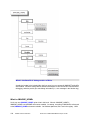
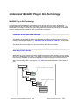
What type of customization/modifications do you need to make? This is the most important question in
determining which ERDAS IMAGINE tools you will need to use. The following figure shows different
levels of customization for ERDAS IMAGINE, you can choose different level of customization based on
what you need to achieve.
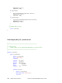
Different Level of Customization
Customize IMAGINE – level 0
IMAGINE BATCH
Customize IMAGINE – level 1
EML + IMAGINE Application Command
Customize IMAGINE – level 2
EML + IMAGINE Spatial Modeler(SML)
Customize IMAGINE – level 3
EML + IMAGINE Developers' C Toolkit
Job
Custom DLL
Application Function DLL
Application
Raster Format DLL
IMAGINE BATCH (level 0) is a very convenient way to streamline your workflow. Most ERDAS
IMAGINE tasks can run in the BATCH mode, there is a Batch button in the processing dialog. This is
useful if you have a process that requires a long time to run and you want to run it when your system is at
minimum utilization (for example, during the night). It is also useful if you wish to run a repetitive task
many times, such as executing the reprojection command to reproject hundreds of images. If you are
familiar with DOS (simulated under Windows) programming, you can write your own DOS batch file, and
10
ERDAS Customer Education
Introduction to ERDAS IMAGINE Developers’ Toolkit
run it without opening ERDAS IMAGINE. Basically IMAGINE BATCH will eventually call IMAGINE
Application Command, so check IMAGINE documentation for more details (IMAGINE Online help>Appendices->Applications Commands->Alphabetical Index)
EML + IMAGINE Application Command (level 1) will provide you a GUI user interface, which is
developed by EML (ERDAS Macro Language). EML comes with every license of the IMAGINE software.
This language is a scripting language that can be used to define the structure and content of the user
interface, as well as provide some fundamental procedural scripting capabilities. Each script is
interpreted at application startup and converted into instructions for the native windowing system (i.e.,
EML user interface constructs are converted to Motif under UNIX and Win32 under Windows). These
files are just copied to the IMGINE_HOME\scripts directory for runtime. Each script is an ASCII
(American Standard Code for Information Interchange) file, which may be edited to change its contents.
EML + IMAGINE Spatial Modeler (SML) (level 2) will add new capabilities to the IMAGINE software
instead of customizing the existing applications. IMAGINE Spatial Modeler is a component of both
IMAGINE Advantage and IMAGINE Professional licenses. Once you have developed a new algorithm
using the graphical Model Maker environment, you can generate SML (Spatial Modeler Language) script.
The best example to demonstrate the capability of SML is Image Interpreter in ERDAS IMAGINE; Image
interpreter is built primarily from SML script with an EML interface. The new application may be plugged
into the existing ERDAS IMAGINE menu/toolbar structure so that it functions like any other part of the
system.
EML + IMAGINE Developers' C Toolkit (level 3) will provide I/O for the ERDAS IMAGINE file format, as
well as functions that make it easier to create an importer/exporter that operates like those that ship with
ERDAS IMAGINE. While the SML language provides over 100 built-in functions spanning many types of
image processing and spatial modeling functions, there are always new developments underway. With
IMAGINE Developers' C toolkit, programmers can create new types of geographic imaging applications
and access many types of imagery through a single interface, as well as deal with many issues such as
resampling or caching. New algorithms developed in the IMAGINE Developers' toolkit can be integrated
into the ERDAS IMAGINE user interface, just like all other ERDAS developed applications.
Toolkit is often used to create JOBs, Custom DLLs and Applications.
•
JOB
A JOB is the simplest way to use Toolkit. It works like other IMAGINE Application commands.
•
Custom DLLs
A major feature of the ERDAS IMAGINE architecture is the use of DLLs to provide for custom
extensions. A DLL is a Dynamically Loadable Library, which is a piece of code to be located and
used at run time by an application. For example, without modification to existing applications, a
Raster Format DLL may be written and added to the system, which allows all ERDAS IMAGINE
applications to access data stored in previously unsupported file format directly and without file
conversion.
Another example is Application function DLLs, which can extend EML built-in functions.
The reason we call a custom DLL a Dynamically Loadable Library is because:
1. The DLL (Dynamically Loadable Library) itself is just a binary file, which is similar to DLLs
(Dynamically Linked Library) generated by Microsoft Visual Studio.
Introduction to ERDAS MAGINE Developers’ Toolkit
ERDAS Customer Education
11
2. The difference between a Dynamically Loadable Library and a Dynamically Linked Library is
the Dynamically Loadable Library is a, not linked time library. While a Dynamically
Linked Library is a linked time library.
If your program needs a DLL (Dynamically Linked Library) called A.dll in order to start,
your program will crash if the A.dll doesn't exist (i.e., your program will search for A.dll
at linked time).
If you have a raster format DLL (Dynamically Loadable Library) e.g. YourFormat.dll, for
IMAGINE, IMAGINE will not crash if YourFormat.dll doesn't exist.
•
Application
The IMAGINE Toolkit Application offers user interaction capabilities, which allows the user to
interact with the IMAGINE Viewer and CellArray by using your mouse.
In summary, you may choose different tools for different tasks, IMAGINE Toolkit provides you
maximum flexibility and the power to customize and extend ERDAS IMAGINE.
Do not use undocumented structures or functions. Also, do not use functions designed for JOBs
in applications, or functions designed for applications in JOBs.
12
ERDAS Customer Education
Introduction to ERDAS IMAGINE Developers’ Toolkit
Class Notes:
Introduction to ERDAS MAGINE Developers’ Toolkit
ERDAS Customer Education
13
Exercise 1: Add an Icon to IMAGINE
Exercise Objective:
This exercise will instruct you on how to add your own IMAGINE icon to the IMAGINE icon panel.
Add your own Icons to IMAGINE
Are you tired of typing “load *.eml” from the command line when you debug EML Scripts? You can load
your eml script by clicking an icon button found on the IMAGINE icon panel. This will save you time when
debugging.
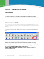
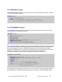
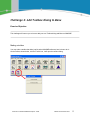
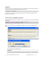
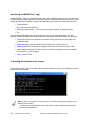
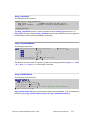
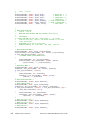
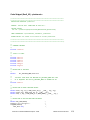
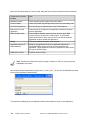
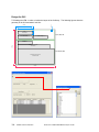
The IMAGINE icon panel looks like: (NOTE: this classic interface is only available to IMAGINE 9.x and
10.x)
Notice the last two icons are created during this training class.
When you create a new user interface in EML, you will typically want to access this script via the
IMAGINE icon panel. To do this, you must create a custom version of IMAGINE.eml and modify it. One
approach you might choose is to add a button to the iconpanel frame that loads your custom EML script.
Note that just as the load command can be used in the Commands dialog to display custom EML GUIs,
this command can also be called from a button in the iconpanel. Fortunately there is an easy way to do
this, you can copy <IMAGINE_HOME>\scripts\tk_iconpanel.inc file to
<IMAGINE_HOME>\scripts\ntx86\tk_iconpanel.inc, and add your icon button by following the
instructions included in the file.
14
ERDAS Customer Education
Introduction to ERDAS IMAGINE Developers’ Toolkit
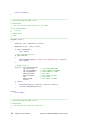
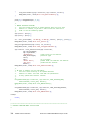
For example, In next section you will create a new EML script named “demo_job.eml”, which takes an
input image and convert it to JPEG2000, you can add the following button to the IMAGINE icon panel:
button btn_debug
{
icon "toolkitdebug.ico";
title "TOOLKIT\nDEBUG";
on mousedown
{
load "demo_job.eml";
}
}
The button should be identified in a meaningful way. All of IMAGINE’s icon panel buttons, are labeled
using icon files. You may not always have the appropriate icon files for new buttons and therefore you
should have a proper “title”. In the above example, we see "\n" between the words "TOOLKIT" and
"DEBUG". The "\n" introduces a line break between the two words and prevents the title string from
running off the edge of the button. When you use a text button instead of an icon button, in the icon
panel, you must use the “geometry” key word (explained later in this course) so that the button will have
the same size and shape as the rest of the buttons on the panel.
Also, by using the load command in the “on mousedown” message handler the need to load this EML
script manually, from the commands dialog, is eliminated.
Introduction to ERDAS MAGINE Developers’ Toolkit
ERDAS Customer Education
15
Note: You should always add a title to an icon button, even if the title doesn’t display. By doing
so, an un-existing ico file can always be replaced by a meaningful title.
Note: If you choose the ”Small Icons” from “IMAGINE Preference->Icon Panel Display Options”,
you need to edit <IMAGINE_HOME>\scripts\ntx86\tk_iconpanelsmall.inc.
The tk_*.inc files are created during the installation of IMAGINE Toolkit, while the spt_*.inc files are
installed during the IMAGINE installation. Although these files are created by different installers they
basically have the same functionality.
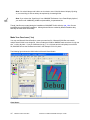
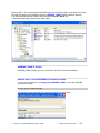
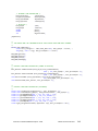
Make Your Own Icons (*.ico)
You may use Microsoft Visual Studio to create your own icon file. Microsoft ICON files can contain
multiple sized ICONs in one single file. When creating an ICON for IMAGINE make sure there is only one
size, i.e. 48 x 48 pixels. If you put 2 different size (e.g., 32 x 32 pixels and 48 x 48 pixels) in one ICON
file, IMAGINE will use the smallest icon which in this example is 32 x 32 pixels.
The following figure shows the ICON editor in Microsoft Visual Studio:
Class Notes:
16
ERDAS Customer Education
Introduction to ERDAS IMAGINE Developers’ Toolkit
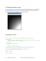
Exercise 2: Add Button to IMAGINE Ribbon
Exercise Objective:
This exercise will instruct you on how to add your own IMAGINE button to the IMAGINE Ribbon.
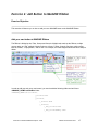
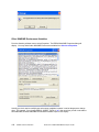
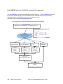
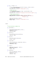
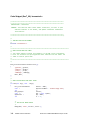
Add your own button to IMAGINE Ribbon
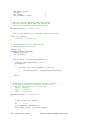
The Ribbon is divided up into Tabs, Groups and Controls. Multiple tabs make up the Ribbon; multiple
groups make up a Tab; multiple Controls make up a Group. Further, Controls may have various styles,
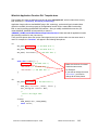
such as “Button,” “Popup Button,” and so forth. For example, the follow diagram shows the basic setup for
ribbon.
In order to add your tab, group, and control, you need to add the following folder and xml files to
<IMAGINE_HOME>\etc\toolbox folder:
<IMAGINE_HOME>\etc\toolbox\
|_toolkit.tlbx
|_toolkit\
|_toolset.tlbx
|_toolset\
|_btn_toolkit.tlbx
|_btn_toolkitdebug.tlbx
Introduction to ERDAS MAGINE Developers’ Toolkit
ERDAS Customer Education
17
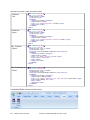
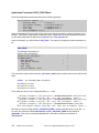
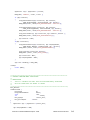
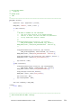
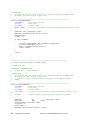
Here are the xml files (*.tlbx) you need to create:
Toolkit.tlbx
“Tab”
Toolset.tlbx
“Group”
Btn_Toolkit.tlbx
“Control”
Btn_Toolkitdebug.tlbx
‘Control”
<?xml version="1.0" ?>
<TLBX start="false">
<name>Toolkit</name>
<type>Tab</type>
<command>
<category>ToolBox</category>
<name>Toolkit</name>
<type info="toolbox\toolkit">Folder</type>
<order>250</order>
</command>
</TLBX>
<?xml version="1.0" ?>
<TLBX start="false">
<name>Toolset</name>
<type>Group</type>
<command>
<category>ToolBox</category>
<name>Toolset</name>
<type info="toolbox\toolkit\toolset">Folder</type>
<order>50</order>
</command>
</TLBX>
<?xml version="1.0" ?>
<TLBX start="false">
<name>Toolkit Tool 1</name>
<type>Button</type>
<controlStyle>IconAndCaptionBelow</controlStyle>
<command>
<category>ToolBox</category>
<name>Toolkit</name>
<type info="demo_job.eml">Script</type>
<icon>Toolkit.ico</icon>
<help></help>
<order>50</order>
</command>
</TLBX>
<?xml version="1.0" ?>
<TLBX start="false">
<name>Toolkit Tool 2</name>
<type>Button</type>
<controlStyle>IconAndCaptionBelow</controlStyle>
<command>
<category>ToolBox</category>
<name>Toolkit Debug</name>
<type info="viewer create at 0 0 size 400 400">Executable</type>
<icon>Toolkitdebug.ico</icon>
<help></help>
<order>50</order>
</command>
</TLBX>
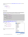
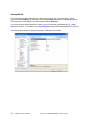
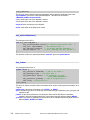
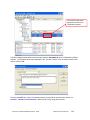
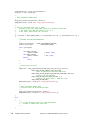
The IMAGINE Ribbon Interface will look like this:
18
ERDAS Customer Education
Introduction to ERDAS IMAGINE Developers’ Toolkit
Section 2: Introduction to IMAGINE EML
Section objective:
This section studies the basic syntax of EML and the built-in functions and techniques used to design a
good GUI. You will also learn how to call IMAGINE application commands from EML.
Introduction to ERDAS MAGINE Developers’ Toolkit
ERDAS Customer Education
19
Introduction of EML
The ERDAS Macro Language (EML) is a script language for creating Graphical User Interfaces (GUIs) in
IMAGINE. Virtually all IMAGINE interfaces from the IMAGINE icon panel to the IMAGINE Viewer have
been constructed with this language. EML allows programmers and non-programmers alike to modify
IMAGINE GUIs and create new GUIs of their own. In addition to its GUI building capabilities, EML
features procedural capabilities that allow simple programming tasks to be achieved such as
automatically naming an output file based on an input file name. Finally, EML is platform independent;
that is, user interfaces designed on UNIX platforms can be transferred to PC platforms
(Windows95/NT/XP) and vice versa. IMAGINE takes care of determining what the windowing system is
on a particular platform and interprets the GUI elements in EML scripts accordingly.
When the designing of ERDAS IMAGINE began, it was clear that a traditional, static GUI would not meet
the needs of the variety of users and applications of the ERDAS product line. Under static GUI structure,
users would not be able to customize the interface and to create scripts which could be used to execute
frequently used functions. The ERDAS Macro Language (EML) is the result of this design.
EML is designed to serve as a scripting language as well as a user interface language. Unlike simple
user interface description tool (such as UIL in motif), EML is able to define the actions which are to be
taken when a user interacts with a dialog. It provides a complete syntax for defining a typical dialog box,
as well as constructs for defining scripts which contain branching and control logic.
In addition to the macro language itself, EML provides a very good connection to Toolkit. Toolkit
programmers can build the EML language into their toolkit application, and to extend the language
through application specific variables, functions, and commands.
All ERDAS IMAGINE GUI interfaces are generated by EML, and ERDAS IMAIGNE itself is the best
example of how to use EML scripts. You may find all of them in folder <IMAGINE_HOME>\Scripts\ . For
example you may find the EML script for the IMAGINE Viewer at
<IMAGINE_HOME>\Scripts\viewer.eml.
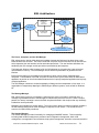
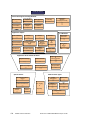
EML Architecture
EML is built from the following major pieces: the Parser, the Interpreter, the Message Manager, the GUI
Manager, and the Session Manager. The following figure shows the EML Architecture.
20
ERDAS Customer Education
Introduction to ERDAS IMAGINE Developers’ Toolkit
EML Architecture
GUI Parts
Components,
Frames,
Frameparts
EML
Scripts
GUI
Manager
EML Parser
GUI
Action Code
Procedures
Interpreter
Message
Manager
Session Manager
The Parser, Interpreter, and the GUI Manager:
EML scripts can be used to define both user interface elements and actions to be taken when a user
interacts with those elements. The Parser reads EML script files and converts them into an internal form
which represents the user interface and its associated procedures. The user interface definitions are
handled by the GUI manager and the procedures are handled by the Interpreter.
The Interpreter: When a script is parsed, all of the GUI elements are converted into a tree structured
representation in memory. The GUI Manager uses its internal representation to generate the user
interface.
Each of the procedures is converted into an internal form which can be quickly evaluated by the
Interpreter. The translation of the EML script into an internal form by the Parser allows an EML based
application to perform at a level somewhere between that of a purely interpreted application and a purely
compiled application.
The GUI Manager controls the creation and display of dialogs and the interpretation of user input. It is
responsible for transparently adapting the EML dialogs to different systems, such as Motif or Windows
NT.
The Message Manager:
EML relies heavily on the use of messages. When the user clicks on a button or selects an item, a
message is generated and sent to the framepart to indicate what event has occurred. When a script is
parsed, the “startup” message is sent to the EML component defined in that script so that any necessary
initialization can be performed.
Messages can originate from several places. The most common place from which messages originate is
the GUI manager which sends event messages in response to user actions. The second source of
events is from within EML procedures.
The Session Manager:
The Session Manager provides functionality for managing an IMAGINE session. This functionality
includes global variable management, preference and configuration management, batch JOB
management, inter-application communication; help system management, interactive command execution
Introduction to ERDAS MAGINE Developers’ Toolkit
ERDAS Customer Education
21
and session log management. Many of these features are implemented by directly incorporating access
to the features into the ERDAS Macro Language syntax and implementation. Therefore, the Session
Manager is currently considered part of EML.
EML Script Structure
EML script consists of the following components: Components, Frames, Frameparts, and action code.
The following figure shows the basic structure of an EML Script.
Components:
All GUI elements in an EML script are contained in a Component. The component is simply a
means of collecting one or more GUI objects into a single named group. The component can not
be visualized; it is only an entry point of the EML script. Each EML script will only have one
component, and the name of the component should be the same as the name of the EML.
Frames:
A Frame is a rectangular region which contains one or more GUI elements called Frameparts. In
IMAGINE, Frames are used in one of two ways. They may be used as document Frames or as
Dialog Frames.
A Document Frame displays information as an image, or as a model, which the user can edit.
A Dialog Frame provides a form with which the user interacts.
Frameparts:
22
ERDAS Customer Education
Introduction to ERDAS IMAGINE Developers’ Toolkit
Every frame is populated with one or more user interface elements. We interact with these
elements as buttons, checkbox, meter bar, and text areas. Each framepart has a list of specific
attributes which define it. There are many different kinds of Frameparts, and they are the key to
building GUI's in IMAGINE.
Procedures (Action Code):
A Procedure is a block of one or more statements which are used to initiate, modify, or control an
operation. Components, frames, and frameparts may all have procedures.
EML Script Structure in action
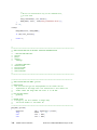
The most basic stand-alone EML script must contain the following elements:
A Component
For those familiar with programming, an EML component is somewhat similar to a main program.
When IMAGINE loads an EML script, it is actually loading the component. Each EML script
contains only one component. By loading the component, IMAGINE gains access to the GUIs it
contains.
The basic syntax of a component is:
COMPONENT <scriptbasename> {
}
Note that the component must be assigned a name and curly brackets are required to open and
close the component. The component name should always be the same as the root name of the
EML script. So if the name of your script is “myscript.eml”, the name of the component should be
myscript. You must observe this rule to avoid confusing the IMAGINE session manager. By
matching component names to unique script file names, you avoid potential problems.
A Frame
An EML frame is a window that stores one or more user interface objects such as buttons or
menus. All GUIs developed with EML must contain a frame in order to interact with the user. All
frames must be enclosed in the script component. Otherwise, IMAGINE cannot access them.
The basic syntax of frame is the same as that for a component:
FRAME <framename>{
}
Just as the component, each frame must be assigned a name. While an EML script will only
contain a single component, a component can contain several frames. Each frame name within a
given component must be unique. Finally, each frame must be opened and closed with curly
brackets.
Introduction to ERDAS MAGINE Developers’ Toolkit
ERDAS Customer Education
23
A GUI Part which allows the user to unload the script (the unload command)
All EML scripts must provide a mechanism for removing the component from the IMAGINE
session. This is because the IMAGINE session cannot load the same script twice. Thus, the only
way to be able to use an EML script more than once in a single session is to provide a mechanism
for removing the script when we are finished using it. The EML command, "unload", must be
issued in order to remove an EML script from the session manager.
The typical mechanism for unloading an EML script is a button framepart. In stand-alone EML
scripts, all button frameparts must contain a mousedown message handler. Whenever a user
clicks on a button in an IMAGINE GUI, a "mousedown" message is sent. The mousedown
message handler (on mousedown) tells the session manager what to do when this message is
received. In the case of a button that is used to remove an EML script from the session manager,
the mousedown message handler must issue the unload command so that the session manager
knows to remove (or "unload") the EML script.
This is the basic syntax for a button which servers to unload an EML script:
BUTTON <buttonname> {
ON MOUSEDOWN {
UNLOAD;
}
}
The button framepart must be contained in a frame. Each frame can have several button (and
other) frameparts. Each framepart must be named. The name must be unique and, by convention,
a framepart name should indicate its purpose. Each framepart must be opened and closed with
curly brackets. While not always required, message handlers such as "on mousedown" must
often be opened and closed with curly brackets. Thus, it is a good practice to always open and
close them in this way.
A Startup message handler (the display command)
Whenever an EML script is loaded in an IMAGINE session, the startup message is issued. A
startup message handler must be included in all stand-alone EML scripts so that the GUIs
contained in the script frames can be presented to the user. Without providing a startup message
handler, the EML script has no means of interacting with the user.
In order to present a GUI to the user, the startup message handler (on startup) must issue the
display command. The syntax of the display command is:
DISPLAY <framename>;
The frame displayed by the startup message handler must contain an interface object such as a
button framepart that allows the user to unload the frame. (See above.) The basic syntax for a
startup message handler is:
ON STARTUP {
DISPLAY <framename>;
}
The startup message handler should appear at the end of the EML component. It must be defined
inside the component but outside any frames defined in the script.
24
ERDAS Customer Education
Introduction to ERDAS IMAGINE Developers’ Toolkit
Now let's look at an example of the most basic type of EML script. We will use this example to
provide context for the above descriptions and to look at some optional features not described in
the basic syntax information provided thus far.
Modifying the EML scripts that comes with IMAGINE
EML not only allows you to create new user interfaces, it also allows you to modify some of the user
interfaces that come with IMAGINE. Among these are the user interfaces that appear in “imagine.eml”.
Before you begin to edit any of the EML scripts provided by ERDAS, you should follow the appropriate
procedures. If you observe these procedures, you will avoid potential problems.
1. Never edit the versions of these scripts found in <IMAGINE_HOME>\scripts
The correct procedure is to copy the script you wish to modify into a custom directory. Edit this new copy
of the script. If you fail to observe this guideline, and edit the script in <IMAGINE_HOME>\scripts, you
may end up having to reinstall IMAGINE because you have inadvertently introduced bugs into the script.
In addition, you are preventing users from accessing the standard version of IMAGINE. This is especially
problematic when your edits simplify the functionality of the interface. Again, editing the wrong version of
the file would mean you would need to reinstall IMAGINE to regain the lost functionality.
2. Copy your version of the EML in to <IMAGINE_HOME>\scripts\Win32Release…
Stand-alone EML vs. Application-bound EML
This manual will focus mainly on what we will call stand-alone EML scripts. These scripts are loaded into
a running IMAGINE session via the Commands dialog or via another EML script. They differ from what
we will call application-bound EML scripts. Application-bound EML scripts are loaded into the IMAGINE
session by C application programs. They are not fully functional unless they are loaded in this way
(Hence using the term application-bound). In order to create a new application-bound EML script, you
must write a C Toolkit application program. We will learn more about application-bound EML script in
Section 7.
In this section, we will focus primarily on stand-alone EML scripts.
How do I know whether an EML script is application-bound?
Because extra caution must be taken when customizing IMAGINE EML scripts that are applicationbound, we will provide some guidelines for determining whether the script you wish to modify is
application-bound. The guidelines are:
1) If a script contains a generic framepart, it is definitely application-bound. However, not all
application-bound scripts contain generic frameparts. So the absence of a generic framepart
indicates nothing.
2) If a script does not contain an on startup message handler, it is definitely application-bound.
But some application-bound EML scripts do have on startup message handlers. So the
presence of this message handler indicates nothing.
3) If the above two guidelines do not provide conclusive information, try the following. For
example purposes, suppose a file named “xxx.eml” is distributed with IMAGINE and that you
want to modify it.
Introduction to ERDAS MAGINE Developers’ Toolkit
ERDAS Customer Education
25
To find out whether “xxx.eml” is a stand-alone EML script, you need to look for the name,
“xxx.eml”, in the other IMAGINE EML scripts. If you find “xxx.eml” in another EML script, and you
find that it is loaded from the other script via the load command, then xxx.eml is definitely a standalone EML script. If you have searched all of the IMAGINE EML scripts and do not find “xxx.eml”
in any of them, then it is definitely an application-bound script.
Note: All EML Scripts distributed with IMAGINE are found in <IMAGINE_HONE>\scripts folder.
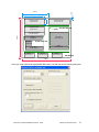
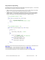
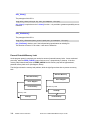
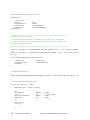
How to design a GUI
The code Snippet (Sec2_02) will generate an empty GUI framework; you may wonder that how to setup
these geometry parameters?
Using Geometry to design a GUI is a simple matter of arithmetic, but it can be very confused and
complex. There is however software, such as Open Office Draw, to help design GUIs. Here are the
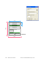
steps to design an EML GUI in Open Office Draw:
(1) Select Tools->Options->OpenOffice.org Draw->General, change unit of measurement to “point”
Note: there is no pixel unit, so select the point unit.
(2) Select View->Zoom->Zoom Factor, change the variable to 76%
Note: changing the zoom factor to 76% will make point units look like pixel units.
(3) Drag a polygon into the layout, you can use your mouse to change its size and location. For the best
accuracy, RMB to open the options dialog box and choose the Position and Size option and specify
the exact value for size and position.
(4) After resize and reposition, you may RMB Position and Size, enable Protect “Position”.
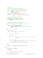
The Open Office Draw output should look like the following figure
26
ERDAS Customer Education
Introduction to ERDAS IMAGINE Developers’ Toolkit
10 px
270 px
200 px
50 px
<filename> Input
20,10, 200,50
<Popuplist> Band
20,80, 200,50
<filename> Output
270,10, 200, 50
[0,0]
270, 90, 200, 220
390 px
<checkbox> Meterbar
20,140, 200, 30
<label>
0,0, 180, 30
<Textnumber>
10,40,60,50
<radiobutton>
10, 40, 180, 130
20,180, 200, 140
<label>
10, 180, 180, 30
<checkbox>
10.100, 180, 30
<button>
20,340,100,40
<button>
160,340,100,40
<button>
300,340,100,40
0,0,490,390
490 px
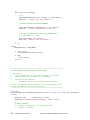
Once your script is parsed through IMAGIE EML library it should look like the following dialog box.
Introduction to ERDAS MAGINE Developers’ Toolkit
ERDAS Customer Education
27
Naming Rule
Take note that each of the Frame Part variables have a similar prefix e.g. “frm_”. It is a good
programming habit to keep certain Naming Rules throughout your program. The following table shows an
example of Naming Rules in EML, which are used in this training manual. You may however wish to use
your own Naming Rule when you return to your office.
28
EML Component & Framepart
Desired Variable Name
EML Component
Use the same name as your EML script
Frame
frm_Name
Group
grp_Name
Button
btn_Name
Filename
fln_Name
EditText
edt_Name
Textnumber
txt_Name
CheckBox
chk_Name
Popuplist
pop_Name
Label
lab_Name
ERDAS Customer Education
Introduction to ERDAS IMAGINE Developers’ Toolkit
Radiobutton
rad_Name
Line
lin_Name
Customized Procedure (action code)
pro_Name()
Customized Application Function (name of the
application function, introduced later in this course)
app_Name()
Introduction to ERDAS MAGINE Developers’ Toolkit
ERDAS Customer Education
29
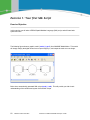
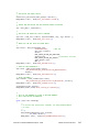
Exercise 1: Your first EML Script
Exercise Objective:
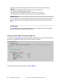
This exercise will help you write your first eml script, and you will learn basic syntax and rules.
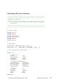
This example will display a dialog with two buttons, clicking on the “Hello World” button will bring you a
message box. The dialog will look like the figure below:
30
ERDAS Customer Education
Introduction to ERDAS IMAGINE Developers’ Toolkit
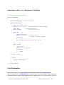
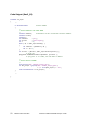
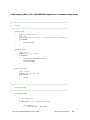
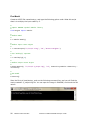
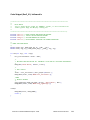
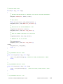
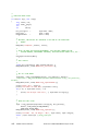
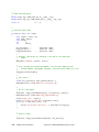
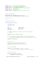
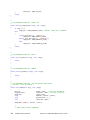
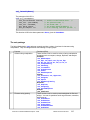
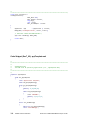
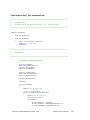
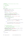
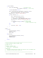
Code Snippet (Sec2_01): “Hello World” EML Script
/*
** YOUR FIRST HELLO WORLD EML SCRIPT.
*/
component HelloWorld
{
frame HelloWorldFrame; # FORWARD DECLARATION
frame HelloWorldFrame
{
title "My First EML Script";
geometry 50, 50, 250,100;
# GEOMETRY BASED ON SCREEN COORDINATE
button OKb;
button cancelb;
# FORWARD DECLARATION
# FORWARD DECLARATION
button OKb
{
title "Hello World!";
geometry 10,30,100,40;
# GEOMETRY BASED ON
# COMPONENT INTERNAL COORDINATE
on mousedown
{
message("Hello World!\n Your first EML.");
}
}
button cancelb
{
title "Cancel";
geometry 130, 30, 100, 40;
on mousedown
{
unload;
}
}
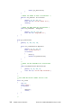
} # CLOSE OF FRAME
on startup
{
display HelloWorldFrame;
}
} # CLOSE OF COMPONNET
Code Explanation:
Note that the component is named “Helloworld” because the script name is “Helloworld.eml”.
Also note that the frame, “HelloWorldFrame”, is declared before it is actually defined. This is known as a
"forward declaration". While forward declarations are not always required, it is good practice to use them
Introduction to ERDAS MAGINE Developers’ Toolkit
ERDAS Customer Education
31
at all times. When you use forward declarations, you tell the EML interpreter that a particular frame or
framepart exists. Without this information, the EML interpreter will fail when frames or frameparts attempt
interact with each other. That is, without a forward declaration, an EML frame cannot interact with a
subsequently defined frames or frameparts.
Note: EML is not case sensitive. For example, COMPONENT and component are the
same in EML.
Comments
The example script contains several strings that start with "/*" and end with "*/" These strings are
comments. As in SML, EML comments are useful for explaining what we intend to do. You must
be very careful to close each comment you open in an EML script. You should also bear in mind
that comments cannot enclose other comments. You may also use “#” to comment the single line
For example:
/* This is
valid */
# This is valid too
/* This is not
*/
valid */
In the third example above, EML will think that there is only a single comment which starts before
the word "This" and ends after the word "not". It will attempt to interpret the string "valid */" as part
of the EML script language and will report an error.
More about Frame
First note that the frame presented in the example contains a title attribute. It has the following
syntax:
TITLE "<title string>";
While the script will function without this attribute, but you should consider the title attribute to be a
required attribute. This attribute causes the frame title to appear in the border of the frame window
when it is displayed. The title makes the purpose of the GUI clearer to the user.
Button framepart Features
As in the frame, a title attribute is used with the button framepart in this script. With buttons, you
should consider the title attribute to be required. It provides the label for the button. Another
mechanism for labeling button frameparts involves using the icon attribute. This attribute is used
with an icon file name and has the following syntax:
ICON <iconfilename>;
32
ERDAS Customer Education
Introduction to ERDAS IMAGINE Developers’ Toolkit
However, even when an icon file is used to label a button, the title attribute should also be used.
This way, if the icon file is not available, the title attribute provides a label that is meaningful to the
user.
You may find icons used by IMAGINE in <IMAGINE_HOME>\cons folder, and they are *.ico and
*.icon. The following statement will load fcopen.icon from <IMAGINE_HOME>\cons folder.
icon "fcopen.icon";
Reserved keywords
When naming frames and frameparts in EML scripts, it is important to avoid using EML reserved
words. In the example script, note that the button has been named "cancel" instead of "quit". This
EML script would fail if we attempted to name the button "quit" because "quit" is a reserved word
in EML. One of the best ways to avoid this problem is to append a character or a string to any
frame or framepart name. For example, for button frameparts, if you always add the letter "btn" or
the string "button" to the part name, you will virtually always avoid inadvertent use of reserved
words.
Geometry
The geometry attribute is one of the most important attributes in EML. It is important that you learn
to use it and become comfortable with it. It is a key element in creating user interfaces that have
the look and feel of standard IMAGINE interfaces. By providing interfaces with this consistent look
and feel, you will make it easier for your users to learn and understand them.
As you will notice when working with EML, most EML frameparts have default geometries. For
example, by default, the size and shape of a button is determined by the title (or by the icon if an
icon file is used to label the button). Similarly, you will also notice that the frameparts defined
within a frame appear from left to right in the order they are defined.
The geometry attribute should always appear with the other attributes at the beginning of the frame
or the framepart. The syntax of the geometry attribute is:
GEOMETRY <x>, <y>, <width>, <length>;
The first two parameters provide information about where the upper left corner of a framepart
should be positioned within a frame. The second two parameters determine the size of the frame
or framepart. It is your responsibility to make sure that the geometries for frameparts within a given
frame do not overlap and that their coordinates represent valid locations within the frame. While
this is a simple matter of arithmetic, it is important to be aware that you are responsible for defining
appropriate geometries.
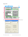
In the “Helloworld.eml”, the geometry can be based on different coordinate system. Geometry for
the frame is based on your screen coordinate, while the geometry for the framepart (i.e. button) is
based on frame internal coordinate. The following figure shows the geometry of “Helloworld.eml”.
Introduction to ERDAS MAGINE Developers’ Toolkit
ERDAS Customer Education
33
[0,0]
Screen coordinate
50 x 50 px
100 px
Frame coordinate
250 px
The Load Command
Once we have written a stand-alone EML script, we need load it in the IMAGINE session using the
load command in order to see what it looks like. The load command can be used both in the
commands dialog and in other EML scripts. The syntax of this command is:
LOAD "<EMLScriptName>.eml";
It instructs the IMAGINE session manager to load the component contained in the script,
"<EMLscriptname>.eml". Note that the script name itself must be enclosed in quotes due to the
fact that it contains the character, ".".
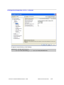
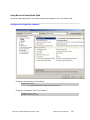
Before you use the load command for the first time, use the preference editor to make sure that the
"Log Message level" preference in the "User Interface & Session" category is set to "verbose".
This will cause all syntax error information to appear in your session log, in addition to the error
message windows that will appear on the screen. Thus, you can dismiss the error message
windows from the display without losing the information they provide.
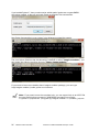
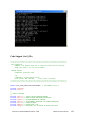
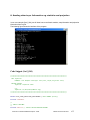
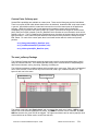
For example, here is how you load your “helloworld.eml” from command line (i.e., type load
“helloworld.eml”, and then press ENTER key).
34
ERDAS Customer Education
Introduction to ERDAS IMAGINE Developers’ Toolkit
Tips for Debugging EML Scripts
As with all programming languages, you will need to debug your EML scripts. Typographical errors
are the most common cause of syntax errors in computer languages. These are the first errors you
should check for when you have problems loading your EML scripts:
•
Is therea missing semicolon “;” on the line preceding the line where the syntax error is
reported?
•
Is there a missing curly bracket ( "{" or "}" ) on any of the lines preceding the line on which the
syntax error is reported?
•
Are there title strings (or other strings) that are missing closing quotes on any lines preceding
the line on which the syntax error is reported?
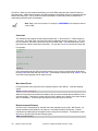
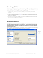
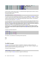
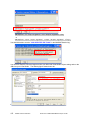
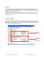
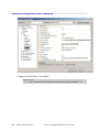
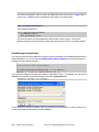
See your Errors in Session Log
IMAGINE Session log is our good friend to debug EML scripts, session log will display the status,
error, and information text generated by all the applications. All the messages in the session log
are date/time stamped. The session log window can be reached from the main icon panel under
the session pulldown menu.
The log message can be of two types in your preference: Verbose and Terse. For troubleshooting
and debugging, however, verbose messages can prove to be more useful.
Verbose
or
terse
Introduction to ERDAS MAGINE Developers’ Toolkit
ERDAS Customer Education
35
Class Notes:
36
ERDAS Customer Education
Introduction to ERDAS IMAGINE Developers’ Toolkit
Exercise 2: An Advanced EML Framework
Exercise Objective:
In this exercise you will create an EML framework, which only contains the GUI components and no
action code. We will add action code in the next exercise.
Here we want to create a EML program which can compress img file to JPEG2000. The GUI interface
may also allow users to select the compression rate. We also, will learn how to design the GUI, and learn
the naming rules for EML scripts.
The code used in this exercise can be found on the course CD (Sec2_02.txt). This code is listed
below.
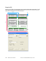
The code used in this exercise will generate an Advanced Demo GUI, e.g. shown below.
Introduction to ERDAS MAGINE Developers’ Toolkit
ERDAS Customer Education
37
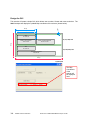
Design the GUI
10 px
270 px
200 px
<filename> Output
270,10, 200, 50
50 px
<filename> Input
20,10, 200,50
<Popuplist> Band
20,80, 200,50
[0,0]
270, 90, 200, 220
390 px
<checkbox> Meterbar
20,140, 200, 30
<label>
0,0, 180, 30
<Textnumber>
10,40,60,50
<radiobutton>
10, 40, 180, 130
20,180, 200, 140
<label>
10, 180, 180, 30
<checkbox>
10.100, 180, 30
<button>
20,340,100,40
<button>
160,340,100,40
<button>
300,340,100,40
0,0,490,390
490 px
Once your script is parsed through IMAGIE EML library it should look like the following dialog box.
38
ERDAS Customer Education
Introduction to ERDAS IMAGINE Developers’ Toolkit
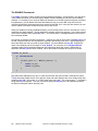
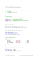
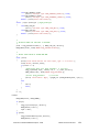
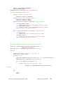
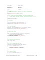
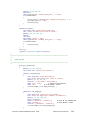
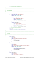
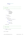
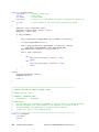
Code Snippet (Sec2_02): Empty GUI Framework (no action code)
/*
*******************************************************************************
**
**
AN ADVANCED EML SCRIPT
**
EXPORT IMG TO ECW WITH DIFFERENT COMPRESS OPTIONS:
**
1. BAND (EITHER GRAYSCALE OR MULTISPECTRAL)
**
2. COMPRESS RATE
**
*******************************************************************************
*/
component Demo
{
frame frm_Demo
{
title "Advanced Demo ( Call IMAGINE JOB)";
geometry 50, 50,490,390;
# GEOMETRY BASED ON SCREEN COORDINATE
statusbar;
# GEOMETRY DOES NOT INCLUDE STATUSBAR
/*
*******************************************************************************
**
**
DECLARATION
**
*******************************************************************************
*/
/*
** FRAMEPART FORWARD DECLARATION
*/
filename fln_Input;
filename fln_Output;
popuplist pop_Bands;
checkbox chk_Meterbar;
group grp_Rate;
textnumber txt_ExactRate;
checkbox PredefineRate;
group grp_PredefineRate;
radiobutton rad_PredefineRate;
label lab_Status;
button btn_OK;
button btn_Batch;
button btn_Cancel;
/*
*******************************************************************************
**
**
INPUT / OUTPUT FILES
**
*******************************************************************************
*/
filename fln_Input
{
geometry 20,10, 200, 50;
Introduction to ERDAS MAGINE Developers’ Toolkit
ERDAS Customer Education
39
# GEOMETRY BASED ON FRAME INTERNAL COORDINATE
title above left "Input File Name:";
select getpref("eml" "default_data_path") + "/*.img";
filetypedef "raster";
shortform;
}
filename fln_Output
{
geometry 270, 10, 200, 50;
title above left "OUtput File name:";
newfile;
select getpref("eml" "default_output_path") + "/*.ecw";
filetypedef "raster";
shortform;
}
line lin_1
{ geometry 20,70,460,1; layout horizontal;}
/*
*******************************************************************************
**
**
JPEG2000 COMPRESS OPTIONS
**
*******************************************************************************
*/
popuplist pop_Bands
{
geometry 20, 80, 200, 50;
title above left "Which band do you want to compress:";
}
checkbox chk_Meterbar
{
geometry 20, 140, 200, 30;
title "Display Meter Bar";
}
group grp_Rate
{
Geometry 20, 180, 200, 140;
label lab_Rate
{
geometry 0,0, 180, 30;
# GEOMETRY BASED ON GROUP INTERNAL COORDINATE
title "Choose Compresss Rate of ECW:";
}
textnumber txt_ExactRate
{
geometry 10, 40, 60, 50;
title above left "Use Exact Compression Rate (2 ~ 10):";
rangespec 2,10;
value 8;
format "2.1";
# 2 IS THE TOTAL NUMBER OF DIGIT,
# 1 IS THE NUMBER OF DECIMAL
delta 0.1;
# THE NUMBER OF INCREMENTED OR DECREMENTED
# WHEN "NUDGERS" ARE USED.
}
checkbox chk_PredefineRate
{
geometry 10, 100, 180, 30;
40
ERDAS Customer Education
Introduction to ERDAS IMAGINE Developers’ Toolkit
title "Use Predefined Compress Rate:";
value 0;
# SETUP DEFAULT TO UNCHECKED.
}
}
group grp_PredefineRate
{
geometry 270, 90, 200, 220;
radiobutton rad_PredefineRate
{
geometry 10, 40, 180, 130;
title "Choose Predefined Quality:";
layout Vertical;
options {2,5,8};
#value "8";#DOESN'T WORK, YOU DON'T NEED TO WORRY ABOUT THAT.
#DEFAULT CHOICE IS ALWAYS 1st CHOICE.
titlelist {"Low Compress Rate (2)",
"Med Compress Rate(5)",
"High Compress Rate (8)"};
}
label lab_Status
{
geometry 10,180, 180, 30;
title "You choice is:";
value $rad_PredefineRate;
}
}
line lin_2
{ geometry 20,330,460,1; layout horizontal;}
/*
*******************************************************************************
**
**
BUTTONS
**
*******************************************************************************
*/
button btn_OK
{
geometry 20,340, 100,40;
title "OK";
info "Process ECW Compression.";
# WILL DISPLAY ON THE STATUS BAR
}
button btn_Batch
{
title "Batch";
geometry 160, 340, 100, 40;
}
button btn_Cancel
{
title "Cancel";
geometry 300, 340, 100, 40;
on mousedown
{
unload;
}
}
} # CLOSE OF FRAME
Introduction to ERDAS MAGINE Developers’ Toolkit
ERDAS Customer Education
41
/*
*******************************************************************************
**
**
COMPONENT PROCEDURE
**
*******************************************************************************
*/
on startup
{
display frm_Demo;
}
} # CLOSE OF COMPONENT
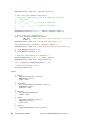
Code Explanation:
The following paragraphs explain the keywords used in the above code (Code Snippet
(Sec2_02)). The keywords used in this exercise are only a sub-set of the available
keywords. For a complete language reference look at the EML menu found in the
<IMAGINE_HOME>\Help\Hardcopy.
The FILENAME Framepart, its attributes, and framepart functions
The FILENAME framepart is the most frequently used framepart in EML. It acts as a bridge between the
data and the EML program.
The FILENAME Framepart
The filename framepart possesses some unique and very useful features. This framepart not
only presents a list of file names within a particular directory, it also permits the user to navigate
through directories to find desired files. These capabilities are built into the framepart itself. To
use these capabilities, you need only define a filename framepart in your EML script. The basic
syntax is:
FILENAME <name>
{
TITLE "<String describing input file type>";
}
A single frame can contain several filename frameparts. Each one must have a unique name
within the frame. While the title attribute is not technically required, you should consider it
mandatory because it explains the purpose of the framepart to the user.
42
ERDAS Customer Education
Introduction to ERDAS IMAGINE Developers’ Toolkit
The NEWFILE Attribute
It is important to understand the default behavior of the filename framepart in order to understand
why an output filename framepart has a slightly different definition than an input filename
framepart. By default, the filename framepart assumes that the file identified by the user already
exists. Thus, if you type the name of a file which does not exist into an input filename framepart,
you will get an error message. If your intention is to use the filename framepart to create a new
file, this presents a problem.
Thus, in order to create a file via the filename framepart, the newfile attribute is required. When
this attribute is used, IMAGINE recognizes that the file specified need not exist. This attribute
provides an additional service if the file specified does exist already. It warns the user that there
is already a file with the specified name and allows the user to decide whether or not to overwrite
the existing file.
You may find example from the example code snippet Sec2_02:
FILENAME fln_Output
{
GEOMETRY 270, 10, 200, 50;
TITLE ABOVE LEFT "OUtput File name:";
NEWFILE;
...
}
The SELECT Attribute for Input Files
The select attribute is only used with the filename framepart. It allows you to filter the list of files
in a particular directory so that only the files of interest are visible. The format of the select
attribute is:
SELECT "<Filter String>";
A common setting for the select attribute in IMAGINE is:
SELECT "*.img";
When the select filename attribute specifies "*.img", the filename framepart displays only files
ending in .img in the directories you navigate. This makes it much easier for the user to find and
select the desired input files.
The select attribute can also be used to set the search directory.
The SELECT Attribute for Output Files
While the select filename attribute provides a very obvious benefit when it comes to selecting
input files, it also provides valuable services for naming output files. Typically with output files,
we need to type in the file name rather than selecting the file from the list that appears in the
filename part. (Indeed, if we did select the output file from a filename part, IMAGINE would warn
us that the file exists and would provide the option of removing the existing file.)
The first benefit of using the select filename attribute with output file names is that you can use it
to set default output directories to directories where you have write permissions.
Introduction to ERDAS MAGINE Developers’ Toolkit
ERDAS Customer Education
43
The second benefit is that it helps avoid inadvertently typing existing file names because these
names appear in the interface. While IMAGINE will warn you about this situation when it occurs,
it is always better to avoid it if you know you do not want to overwrite any existing files.
The third benefit is that all the user needs to type is the base name for the file and IMAGINE will
automatically append the filter string if specified. For example, if you use "*.img" filter string with
the select attribute, then if you type the word "out" in your output filename framepart, IMAGINE
will automatically convert it to "out.img". You should always try to make the user's work easier
when you create GUIs with EML scripts. The select filename attribute is often a very good way to
do this.
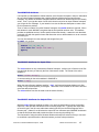
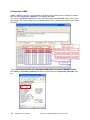
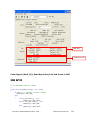
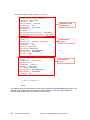
The SHORTFORM Attribute
The shortform filename attribute simply gives the filename framepart a different appearance. By
default, the filename framepart displays the list of files. When the shortform attribute is used,
this list does not appear. Only the name of the selected file appears. Note that the user can still
navigate the directory structure and select files via a visual interface. All the user needs to do is
to click on the file icon that appears to the right of the text field for the file name.
The shortform attribute is especially useful in very complex interfaces. The more compact
representation can often make the GUI clearer to the user. The shortform attribute should
always appear with the other filename attributes at the top of the filename description. The
syntax for this attribute is:
FILENAME fln_Output
{
...
SHORTFORM;
...
}
The following figure demonstrate the difference between with and without the shortform
keyword.
Without "shortform"
keyword
With "shortform"
keyword
44
ERDAS Customer Education
Introduction to ERDAS IMAGINE Developers’ Toolkit
FILENAME functions
In addition to its directory navigation and file naming services (checking to see if input files exist,
automatically appending file extensions, warning if output files already exist), the filename
framepart possesses framepart functions. These functions provide information about the file
entered via the filename framepart. These functions are accessed via the name of the filename
framepart followed by “.<functionname>”. So if the filename framepart was named infile, we
would access the filename framepart functions as follows:
$fln_Input.<functionname>();
One very useful filename function in writing EML interfaces for SML scripts is the .datatype()
function. This function assumes a raster input file and returns a string representing the pixel type
such as "U8", "U16", "F32", etc. You can use these values to send appropriate arguments to
SML scripts to set data types for input and output files.
You may find example in the following section.
The GETPREF() Command
Understand Preference Definitions before we get to GETPREF() Command
When you use the Preference Editor to modify preferences, you are actually modifying the
settings of specific preference values. The initial values for these preferences are stored in
Preference Definition Files (“*.pdf” files) which are found in <IMAGINE_HOME>\defaults. It is
important to be aware of the existence, location, and names of the .pdf files in order to use the
EML getpref() function.
Each “*.pdf” file in <IMAGINE_HOME>\efaults contains preferences for a particular preference
category. The preference category most commonly modified by IMAGINE users is the "User
Interface & Session" category. If you examine the “*.pdf” files in <IMAGINE _HOME>\default you
will see that the name of the file associated with this category is “eml.pdf”. The basename of this
file, eml, will be important when we use the getpref() function in EML.
The general syntax for a preference in a “.pdf” file is:
<preferencename>("<preferencetitle>"): <defaultvalue>
"<bubblehelpinfo>"
<preference attributes>
Let's look at an example to understand this better. Many IMAGINE programs use
<IMAGINE_HOME>\examples as the default directory for finding input image files. The
preference used to find this directory is default_datapath and is found in “eml.pdf”. Here's the
preference definition:
default_data_path("Default Data Directory"):
"$IMAGINE_HOME/examples"
"Default data path for images"
maxlength 256;
Introduction to ERDAS MAGINE Developers’ Toolkit
ERDAS Customer Education
45
First we see the preference name is default_data_path. The preference name is required when
using the getpref() function. Next we see the preference title which appears to the left of the
preference setting when the Preference Editor is displayed.
Next is the default value for the preference. This is the value of the preference before any user
attempts to modify preference settings.
Next we see the string that will appear on the screen when bubble help is enabled.
Finally, we see the maxlength attribute. There are different types of preferences (e. g., strings,
numbers) and each type has its own attributes. In this case, the maxlength attribute indicates
that default_data_path cannot contain more than 256 characters. When you work with the
getpref() function, you will only need to concern yourself with the name of the preference you
wish to access and the name of the .pdf file which contains this preference.
You should be aware that when you change preference values via the Preference Editor, the
changes are not written to the .pdf files but rather to one of two v8preference files. When you
save changes at the user level, the new preference value is stored in a v9preference file found in
the “.imagine910” directory under your home directory. If you have the required write
permissions, you can also save preferences at the global level. The v9preference file which
stores these changes is found in the <IMAGINE _HOME>\defaults directory.
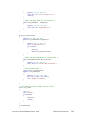
The GETPREF() Command
The getpref() function allows you to extract a preference value for use in an EML script. It has
the following syntax:
GETPREF ( "<pdfbasename>", "<preferencename>" ) ;
If, for example, you wanted to extract the "Default Data Directory" preference from the "User
Interface & Session" category, you could call the getpref() function as follows:
GETPREF ( "eml", "default_data_path" ) ;
In this case, eml is the base name of the file, eml.pdf, which stores the "User Interface & Session"
category. The string, default_data_path, represents the name of the preference associated with
"Default Data Directory".
When the getpref() function is called, it looks in three different places for the value of the
specified preference. First, it looks to see if there is a v8preference file in your .imagine830
directory. If there is, it checks to see whether the preference you have specified appears in the
file. If so, getpref() uses this value. Otherwise, it checks to see whether there is a v8preference
file in the <IMAGINE_ HOME>\defaults directory. Again, if the file is found and the specified
preference appears in it, getpref() will use this value. If getpref() does not find the preference
setting in either of these two files, it uses the default value from the .pdf file.
One example of how the getpref() function can be used is to set paths with the select filename
attribute. For example:
SELECT GETPREF ( "eml", "default_data_path" ) ;
would automatically position the filename selector in the defalult_data_path directory. This can
be further enhanced by appending a filter string to the end of the path as follows:
46
ERDAS Customer Education
Introduction to ERDAS IMAGINE Developers’ Toolkit
SELECT GETPREF ( "eml", "default_data_path" ) + "/*.img";
Using the select filename attribute in this way not only automatically positions the filename
framepart in the directory specified by default_data_path, but it will only display the files in that
directory which end in “.img”.
Note: You may find detailed description about preference database
from EML User Manual.
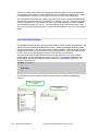
The RADIOBUTTON Framepart
The radiobutton framepart is used to present a short list of options to a user. Actually we should call it
readiogroup, because it consists of one or more entries each with a radio button displayed to the left of it.
Typically, the radiobutton framepart should not be used to present more than four or five options. This
framepart is similar to the buttons on a car radio. All options are visible but only one can be selected at
any given time. It is because all options are always visible that this framepart should only be used for
short lists of options. Otherwise, it can take up too much space in the interface. Also, when too many
options are simultaneously visible, it can make the interface very confusing.
The basic syntax for the radiobutton framepart is:
RADIOBUTTON <optionlistname>
{
TITLE "<optionlisttitle>";
OPTIONS { "<opt1>", "<opt2>",..., "<optn>" }; # VALUE OF THE RADIOBUTTON
VALUE "<defaultvalue>";
TITLELIST {"Info1","Info2",...,"Infon"}; # DISPLAY ON THE GUI
}
You may also put numeric value on the options; it will act the same as the string.
RADIOBUTTON <optionlistname>
{
TITLE "<optionlisttitle>";
OPTIONS { <opt1>, <opt2>,...,<optn> };
VALUE <defaultvalue>;
TITLELIST {"Info1","Info2",...,"Infon"};
}
# VALUE OF THE RADIOBUTTON
# DISPLAY ON THE GUI
The options attribute provides the complete list of values associated with this framepart. Just as in the
textnumber framepart, the value attribute can be used in the radiobutton framepart to set a default
selection. Otherwise, the first value in the options list will be selected by default.
Another useful attribute is the titlelist attribute. You can use this attribute to provide descriptive names
for the options in the options list. Finally, the layout attribute can be used to set the orientation of the
buttons. By default, the buttons are displayed vertically. The layout attribute can be used to force the
orientation to be either horizontal or vertical.
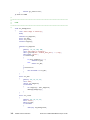
Here is an example of a radiobutton framepart as it appears in an EML script:
radiobutton rad_PredefineRate
Introduction to ERDAS MAGINE Developers’ Toolkit
ERDAS Customer Education
47
{
geometry 10, 40, 180, 130;
title "Choose Predefined Quality:";
layout Vertical;
options {2,5,8};
# VALUE OF THE RADIOBUTTON
value 8;
# SETUP DEFAULT CHOICE
titlelist {"Low Compress Rate (2)",
"Med Compress Rate(5)",
"High Compress Rate (8)"};# DISPLAY ON THE GUI
}
Notice that the buttons are vertically aligned because of the layout attribute. Notice also that the strings in
titlelist appear in the interface. If the titlelist attribute were not used here, then the values from the
options list would appear as the button titles. Finally, notice that the third button is automatically selected
because of the value attribute. If the value attribute were not used here, the first button would be
selected by default.
The POPUPLIST Framepart
Like the radiobutton framepart, the popuplist framepart presents the user with a list of options. However,
in this case, only one of the options is visible at a time until the user clicks on the framepart. This causes
the entire list of options to appear. In contrast to the radiobutton framepart, the popuplist framepart is
useful for presenting long lists of options.
The basic syntax for the popuplist framepart is:
POPUPLIST <name>
{
TITLE "<optionlisttitle>";
NAMES { "<optl>", "<opt2>",
"<optn>" };
TITLELIST {"Info1","Info2",...,"Infon"};
VALUE "<defaultvalue>";
}
The names attribute serves the same purpose as the options attribute in the radiobutton framepart. By
default, the names list provides the titles for the popuplist. However, just as with the radiobutton
framepart, the titlelist attribute can be used in the popuplist framepart to present more descriptive titles
for the options provided in the names attribute list.
And, as with the textnumber and radiobutton frameparts, the value attribute can be used to set the default
value for the popuplist.
In our example, the content of popuplist will be automatically setup by input filename. You will learn that
in the following section.
48
ERDAS Customer Education
Introduction to ERDAS IMAGINE Developers’ Toolkit
The CHECKBOX Framepart
The checkbox provides a toggle mechanism for on/off, yes/no, true/false types of response. The basic
syntax for the popuplist framepart is:
CHECKBOX <name>
{
TITLE "<checkboxtitle>";
VALUE 1; # SETUP DEFAULT TO CHECKED (1), UNCHECKED (0)
# NOTE $CHECKBOX WILL ALWAYS BE NUMBER 0/1, NOT STRING
}
The TEXTNUMBER Framepart
The textnumber framepart provides an interface that allows users to conveniently set numeric values.
The basic syntax of a textnumber framepart is:
TEXTNUMBER <name>
{
TITLE "<numbertitle>";
MIN <minvalue>;
MAX <maxvalue>;
RANGESPEC <minvalue>, <maxvalue>; # CAN REPLACE min, max
VALUE <defaultvalue>;
DELTA <Incremented or decremented nudgers>;
}
The min and max attributes are used to set the minimum and maximum values that the user is allowed to
enter. This can help users avoid making mistakes because the textnumber interface will prevent them
from making inappropriate choices. An additional attribute that can be used with the textnumber
framepart is the value attribute. This attribute sets a default value for the textnumber part. If the value
attribute is not used, the default value is the minimum value set by the min attribute.
Let's look at an example. This is textnumber framepart description from an EML script:
textnumber txt_ExactRate
{
geometry 10, 40, 60, 50;
title above left "Use Exact Compression Rate (2 ~ 10):";
rangespec 2,10;
value 8;
format "2.1"; # 2 IS THE TOTAL NUMBER OF DIGIT,
# 1 IS THE NUMBER OF DECIMAL
delta 0.1; # THE NUMBER OF INCREMENTED OR DECREMENTED
# WHEN "NUDGERS" ARE USED.
}
Note that because the value attribute has been set to 8, the number 8 automatically appears when the
frame is displayed. If we had not used the value attribute, the number 1 would automatically appear.
Introduction to ERDAS MAGINE Developers’ Toolkit
ERDAS Customer Education
49
Class Notes:
50
ERDAS Customer Education
Introduction to ERDAS IMAGINE Developers’ Toolkit
Exercise 3: Initialize Popuplist and Output Filename
Exercise Objective:
During this exercise you will add action code into the GUI framework. You will populate the Band list
(Popuplist) and output (Filename) when you select your input image.
During the last exercise you learn how to design a GUI. The next step is to fill in the framework with your
business logic. In this exercise you will learn the basic EML flow control statements and other useful
functions.
In the code, below, you will learn how to automatically supply the output file name when you select the
input file. You will also learn how to populate the file layer names into the popuplist framepart.
Here is what you should do:
Introduction to ERDAS MAGINE Developers’ Toolkit
ERDAS Customer Education
51
Code Snippet (Sec2_03)
filename fln_Input
{
...
on filenamechoosen
# EVENT HANDLER
{
/*
** SETUP POPUPLIST FOR LAYER NAME
*/
variable namelist;
# VARIABLES CAN ONLY BE DEFINED IN EVENT HANDLER.
variable titlist;
variable i;
set namelist
= {"0"};
set titlist
= {"All Layers"};
set i
= 1;
while ( $i <= $fln_Input.nbands() )
{
set namelist = {$namelist, $i };
set i = $i +1;
}
set titlist = {$titlist, $fln_Input.RasterLayerList() };
# SETUP LIST
$pop_Bands.SetNameAndTitleList($namelist ,$titlist );
# $pop_Bands IS A STRING, EVEN THE NAME IS NUMERIC
}
/*
** SETUP OUTPUT FILEANME
*/
echo getpref("eml" "default_output_path");
set fln_Output = getpref("eml" "default_output_path")
+ "/"+ froot($fln_Input) + ".ecw";
send filenamechoosen to fln_Output;
...
}
52
ERDAS Customer Education
Introduction to ERDAS IMAGINE Developers’ Toolkit
Code Explanation:
EML Message and Message Handler
The FILENAMECHOOSEN Message and its Handler
Unlike the startup message, which is strictly associated with loading an EML script, and the
framedisplay message, which is strictly associated with displaying a frame, the
Filenamechoosen message is associated with a variety of frameparts. Among these is the
filename framepart.
Whenever a file name is selected or typed in to the filename framepart (and press enter), the
Filenamechoosen message is sent. If you wish to trigger particular actions whenever a file
name is selected, you can define an on Filenamechoosen message handler within the filename
framepart. As with the mousedown message handler discussed above, the on
Filenamechoosen message handler should be defined at the end of the framepart that uses it.
For example, the basic syntax for a filename framepart that includes an on Filenamechoosen
message handler would be:
filename <name>
{
title "<titlename>";
on filenamechoosen # Message Handler
{
(actions to take when input message is sent)
}
}
A typical use for the on Filenamechoosen message handler in a filename framepart is to enable
another framepart which requires the file name. We will see an example of this when we look at
the enable command.
The FRAMEDISPLAY Message and its Handler
Whenever a frame is displayed from an EML script, a framedisplay message is sent. Just as the
on startup message handler (see above) is used to define what should happen when an EML
script is loaded, the on framedisplay message handler can be used to define what should
happen when a frame is displayed.
The on framedisplay message handler must be defined within the frame that uses it but must be
outside any of the frameparts that exist in the frame. By convention, the on framedisplay
message handler is defined at the end of the frame. The basic syntax for a frame that contains
an on framedisplay message handler is:
Introduction to ERDAS MAGINE Developers’ Toolkit
ERDAS Customer Education
53
frame <name>
{
title "<title>";
...framepart definitions...
on framedisplay
{
(actions to take when frame is displayed)
}
}
For an example of the on framedisplay message handler, refer to the discussion of the disable
command below.
The VALUECHANGED Message and its Handler
The valuechanged message is similar to the input message except that a valuechanged
message is issued for each change made to a framepart including changes involving individual
keystrokes. While applicable to several frameparts, the on valuechanged message handler is
typically applied to the textnumber and meternumber frameparts.
The basic syntax for the on valuechanged message handler is the same as for other message
handlers:
on valuechanged
{
(actions to take when valuechanged message is sent)
}
Variable and Array List, and the Set Command
The VARIABLE and the Set Command
A variable may be either local (variable) or global (global).
Local variables defined at the component level are available to all procedures, menus and
frames defined in the component.
Global variables are available across applications. Any variable used in an EML script should be
declared as either global or variable.
The syntax for defining a variable is:
variable name ;
global name ;
In either case a variable is a named container which may hold one or more values which can be
numbers, characters, or strings of characters.
54
ERDAS Customer Education
Introduction to ERDAS IMAGINE Developers’ Toolkit
The value of a variable may be established with the set command. The $ operator is used to get
the value of a variable.
The syntax for retrieving the value of a variable is:
$name
The Array List and set Command
The { } (list construction) operator creates a single item which contains multiple values. This is
like an array in other programming languages and may be indexed via the [ ] (index) operator.
The individual expressions between the braces may be space or comma separated.
Note: The Index of List always starts from 1, not 0.
Here is an example on how to use list.
variable listname;
set listname = {1, 2, 3};
# INIT LIST
set listname = {$listname, 4}; # APPEND LIST
Introduction to ERDAS MAGINE Developers’ Toolkit
ERDAS Customer Education
55
Flow Control Statement
The IF Statement
The If() flow control (or conditional) statement is common to many computer languages. Often in
EML, we use commands and functions directly. But sometimes we will want to check for specific
conditions to determine whether it is appropriate to execute certain commands or conditions.
Here is a conceptual example that illustrates the general purpose of the If() statement:
If the user has provided all of the required inputs, then execute the model. The syntax of the If()
statement in EML requires that the condition evaluated appears in parentheses. When the
condition is true, one or more commands or functions can be executed as a result. In order to
associate more than one action with a condition, the actions must be enclosed in curly brackets ({
}). So the basic syntax for an If() statement in EML is:
if ( <condition> )
{
(actions)
}
else if ( <condition> )
{
(actions)
}
else
{
(actions)
}
One application for the if() statement is to enable a framepart that has been disabled. The if()
statement can be used to verify that the user has provided the inputs required to justify enabling
another framepart. We will see an example of this in our discussion of the enable command
below.
Typical conditions evaluated by the If() statement include checks for:
Operators
Equality (is equal to)
Inequality (does not equal)
Greater than
Greater than or equal to
Less than
Less than or equal to
==
!=
>
>=
<
<=
The WHILE Statement
56
ERDAS Customer Education
Introduction to ERDAS IMAGINE Developers’ Toolkit
The while() statement allows you to repeatedly execute a set of functions or commands. This
sort of repetitive processing is generally referred to as a "loop". The while() statement is only
one example of a looping mechanism in EML. Other examples include the foreach() statement
and the loop() statement. See the Appendix C for more information about these.
In EML, loops are typically used to run the same model (or other JOB program) several times.
The basic syntax of a while statement is:
while ( <condition is true> )
{
<action1>;
<action2>;
}
Notice that like the If() statement, the while() statement evaluates a condition. However, the if()
statement evaluates the condition only once whereas the while() statement evaluates the
condition repeatedly until it is no longer true.
Let's look at an example. This is while() example from an EML script:
while ( $i <= $fln_Input.nbands() )
{
set namelist = {$namelist, fmt($i,"?") };
set i = $i +1;
}
In this case While() statement will setup an array list, and fill in with the band number. If the band
number is 3, in the end the array list will be {“0”, “1”, “2”, “3”}.
The FPATH(), FROOT(), FEXT(), and FMT() Command
When you enter a filename via the filename framepart, the full path and name of the file is contained in
the filename variable. That is, although the user interface appears to show only the name of the file, the
filename framepart contains the full path information as well.
The fpath() function can be used to extract the directory path from a filename framepart or from any other
string containing a file path.
The froot() function extracts the root name of a file from its full path.
The fext() function extracts the file extension from a file name.
Here is an example of how to use these command together:
filename fln_Input
{
on filenamechoosen
# EVENT HANDLER
{
echo "filename=" $fln_Input;
echo "Fpath()=" Fpath($fln_Input);
echo "Froot()=" FROOT($fln_Input);
echo "Fname()=" FNAME($fln_Input);
echo "Fext()=" FEXT($fln_Input);
}
}
In the Session Log, you will see:
Introduction to ERDAS MAGINE Developers’ Toolkit
ERDAS Customer Education
57
13/08/07
13/08/07
13/08/07
13/08/07
13/08/07
15:39:10
15:39:10
15:39:10
15:39:10
15:39:10
SessionMgr(4936):
SessionMgr(4936):
SessionMgr(4936):
SessionMgr(4936):
SessionMgr(4936):
filename = d:/work/data/2-2.img
Fpath()= d:/work/data/
Froot()= 2-2
Fname()= 2-2.img
Fext()= img
The fmt function is used to format numbers. It converts the number argument (which must be a number)
into a string using the format control string.
The syntax of this function is:
fmt (<numericvalue>, "<formatstring>");
The numeric value can be represented as a number (e.g., 2) or as a variable (e.g., $numval). There are
a variety of format control strings including strings for representing dates and times. However, the control
strings you will typically want to user are those representing digits in decimal numbers. The characters
used in these format strings are, "0", "#" and "?".
You can include decimal points in format control strings to indicate how many digits are desired before or
after the decimal point. You can also include commas to indicate that thousands digits should be comma
delimited. While the "#" character will format the number with the minimum digits required to represent it,
the "0" and "?" characters provide space holding features. When "0" is used in these strings, leading and
trailing zeros will appear in unoccupied spaces in the formatted number string.
Similarly, when "?" is used, leading and trailing blank spaces will appear in these locations. Note that
when integer formats are defined for floating point numbers, the fmt() function will round the value to the
nearest integer. Here are some examples of formatted numbers produced by using these format control
characters.
Consider the following assignments:
variable num;
set num = fmt (2.4, "##.##");
set num = fmt (2.4, "00.00");
set num = fmt (2.4, "??.??");
The variable, num, would take on the following values respectively:
2.4
02.40
2.4
The SEND Command
The send command delivers a message to a destination. Messages are typically generated and
delivered by the core of the EML system in response to user input events. However, messages may be
explicitly generated and delivered using the send command.
The syntax of send command is:
SEND <message> to <Frame or framepart>
Here is an example of a Send command as it appears in an EML script:
58
ERDAS Customer Education
Introduction to ERDAS IMAGINE Developers’ Toolkit
filename fln_Input
{
...
on filenamechoosen
# EVENT HANDLER
{
...
send filenamechoosen to fln_Output;
...
}
}
fln_Input will send a filenamechoosen message to fln_ouput, the Message handler from fln_output
will response to this message.
Introduction to ERDAS MAGINE Developers’ Toolkit
ERDAS Customer Education
59
Class Notes:
60
ERDAS Customer Education
Introduction to ERDAS IMAGINE Developers’ Toolkit
Exercise 4: Output Debug Information
Exercise Objective:
There is no built-in debug tool for EML, so printing the debug information to the IMAGINE session log is
very helpful. In this exercise, you will learn how to print debug information.
It is very useful to output debug information when you are debugging EML script, you can add the
following code block into the framework you used during exercise 2 and 3.
Code Snippet (Sec2_04): Output Debug Information
filename fln_Input
{
...
on filenamechoosen
# EVENT HANDLER
{
/*
** OUTPUT DEBUG INFO
*/
echo "The File Type (Truecolor, greycolor, pseudocolor, annotation,
coverage) is :"
+ $fln_Input.FileType();
echo "The Data Type (U8, U16, S8, S16..) is :"
+ $fln_Input.Datatype();
echo "Pixel size [height, width] unit is :"
+ "[" + $fln_Input.pixelheight +","
+ $fln_Input.pixelwidth + "] "
+ $fln_Input.units();
}
...
}
popuplist pop_Bands
{
...
on valuechanged
{
/*
** OUTPUT DEBUG INFO
*/
echo "$pop_bands=" $pop_bands;
}
...
}
Introduction to ERDAS MAGINE Developers’ Toolkit
ERDAS Customer Education
61
group grp_Rate
{
...
textnumber txt_ExactRate
{
...
on valuechanged
{
/*
** OUTPUT DEBUG INFO
*/
echo "Current Rate is" + $txt_ExactRate;
}
...
}
...
}
Code Explanation:
The ECHO Command
The Echo command prints its arguments to the session log. There may be any number of arguments of
either string or numeric type. A newline is printed after all of the arguments. This command is typically
used to debug EML scripts.
The echo command has the following syntax:
echo <arg1> <arg2> ... <argn>;
echo <arg1>, <arg2> ,..., <argn>;
echo <arg1> + <arg2> + ... + <argn>;
62
ERDAS Customer Education
Introduction to ERDAS IMAGINE Developers’ Toolkit
Class Notes:
Introduction to ERDAS MAGINE Developers’ Toolkit
ERDAS Customer Education
63
Exercise 5: Disable & Enable Framepart
Exercise Objective:
This exercise instructs you on how to disable and enable the frameparts when necessary.
You can add the following code block into the framework we used in exercise 4.
Code Snippet (Sec2_05): Disable / Enable Framepart
group grp_Rate
{
checkbox chk_PredefineRate
{
...
on valuechanged
{
if ($chk_PredefineRate == 1)
{
enable grp_PredefineRate;
disable txt_ExactRate;
}
else
{
disable grp_PredefineRate;
enable txt_ExactRate;
}
}
}
...
}
filename fln_Output
{
...
on filenamechoosen
{
if ($fln_Input != "" && $fln_Output!= "")
{
enable btn_OK;
enable btn_Batch;
64
ERDAS Customer Education
Introduction to ERDAS IMAGINE Developers’ Toolkit
}
}
...
}
...
on framedisplay
{
disable grp_PredefineRate;
disable btn_OK;
disable btn_Batch;
}
Code Explanation:
The DISABLE Commands
In the user interfaces you create with the EML script language you will often find it is wise to disable
different frameparts that appear in a frame. This is often done to help the user avoid making mistakes.
For example, if the EML script you create is intended to apply a spatial model to an input file and create
an output file, the model will fail if either the input file or the output file has not been specified. If a button
is used to run the model, this button can be disabled until the user provides both file names.
The disable command can be used to disable any framepart. The disable command has the following
syntax:
disable <framepartname>;
The disable command is commonly used in the body of an on framedisplay message handler. In the
example described above, the disable command could be used to disable the button that runs the model.
If the name of the button framepart was okbutton, the on framedisplay message handler for this frame
would look like this:
on framedisplay
{
disable grp_PredefineRate;
disable btn_OK;
disable btn_Batch;
}
It is a good idea to use the disable command to help the user avoid making mistakes. However, if you
elect to use it, you must remember to include the enable command (see below) so that the user can
execute models and commands once the required inputs and outputs have been specified.
Introduction to ERDAS MAGINE Developers’ Toolkit
ERDAS Customer Education
65
The ENABLE Commands
The enable command is used to enable previously disabled frameparts. As mentioned in our discussion
of the disable command, you will often want to disable certain frameparts to help users avoid making
mistakes. For example, if you create an EML user interface to run an SML script that requires command
line parameters, you can disable the button that allows the user to run the SML script until all of the
required command line arguments have been entered via the EML GUI. Once they are entered, you can
use the enable command to enable the button and run the model.
When you enable a previously disabled framepart, you will usually need to check to see that one or more
conditions have been satisfied. The if() statement is typically used for this purpose. You will also need to
check these conditions at the appropriate times. This is often done in message handlers such as the on
input message handler.
Let's look at an example of how this might work. Suppose you want to use a button called btn_OK to run
an SML script that requires one command line argument representing a file name. Upon displaying the
frame that allows the user to provide the input filename, you would disable the btn_OK. Suppose the
name of the filename part for the output file is fln_Output. You could use an on Filenamechoosen
message handler and a conditional statement (see information about flow control in EML below) to
determine when btn_OK should be enabled. Here's the filename framepart we could use to do this:
filename fln_Output
{
on filenamechoosen
{
if ($fln_Input != "" && $fln_Output!= "")
{
enable btn_OK;
enable btn_Batch;
}
}
}
Note that before enabling the btn_OK, we make sure that the user has provided a valid input file name.
The If() statement literally means, "if the string for input and output filename are not an empty string, then
enable the btn_OK." The symbol "!=" in EML means "does not equal". The empty quotes, “”, represent a
string that has no characters. This way, we avoid enabling the btn_OK if the user inadvertently enters
the filename framepart without selecting a file.
66
ERDAS Customer Education
Introduction to ERDAS IMAGINE Developers’ Toolkit
Class Notes:
Introduction to ERDAS MAGINE Developers’ Toolkit
ERDAS Customer Education
67
Exercise 6: Call IMAGINE Application Command
Exercise Objective:
In order to fully utilize the powerful IMAGINE commands, we can call IMAGINE application commands
from the EML script. This exercise will show you useful techniques and related EML commands.
Note: If your program is no working please let the instructor know. You are about to start real
data processing i.e. you will be using the command exportecw , an IMAGINE
application command, to convert an img file to ECW.
To convert an .img to ECW you need to add the following code block to the framework used in exercise 5.
68
ERDAS Customer Education
Introduction to ERDAS IMAGINE Developers’ Toolkit
Code Snippet (Sec2_06): Call IMAGINE Application Command (exportecw)
/*
*******************************************************************************
**
**
BUTTONS
**
*******************************************************************************
*/
button btn_OK
{
geometry 20,340, 100,40;
title "OK";
info "Process ECW Compression."; # WILL DISPLAY ON THE STATUS BAR
on mousedown
{
pro_ExportECW();
}
}
button btn_Batch
{
title "Batch";
geometry 160, 340, 100, 40;
on mousedown
{
batchjobname froot($fln_Output);
startbatchsingle;
pro_ExportECW();
}
}
button btn_Cancel
{
title "Cancel";
geometry 300, 340, 100, 40;
on mousedown
{
unload;
}
}
/*
*******************************************************************************
**
**
FRAME PROCEDURE
**
*******************************************************************************
*/
on pro_ExportJPEG
{
/*
** CALL IMAGINE JOB
*/
if ($pop_Bands == "0") # PROCESS ALL BANDS
{
job exportecw
-inputfilename
$fln_Input
Introduction to ERDAS MAGINE Developers’ Toolkit
ERDAS Customer Education
69
-outputfilename $fln_Output
-compratio $txt_ExactRate
-photointerp Multispectral;
}
else
{
# PROCESS INDIVIDUAL BAND
variable band;
set band = $pop_bands.GetListIndex();
# INDEX START FRMO 1, BAND START FROM 1.
job exportecw
-inputfilename
$fln_Input
-outputfilename $fln_Output
-bands $band
-compratio $txt_ExactRate
-photointerp Grsyscale;
}
}
Code Explanation:
Buttons for Executing Commands
Buttons here will look like the button described above for unloading an EML script. However, in this case,
the mousedown message handler (on mousedown) will be used to run an IMAGINE Application
Command. The command, “Exportgeojp2”, used here will compress your input image to JPEG2000
format, and you may able to change the compress rate and band.
The JOB Command
The job command is used only with IMAGINE JOB programs. These programs require initial input
information from the user but do not interact with the user while they run. In general, they are data
processing programs. Examples of IMAGINE JOB program are the IMAGINE Import and Export
programs. The job command tells the IMAGINE session manager that the program is an IMAGINE
JOB program. The session manager displays the progress meter as a result.
You may find all IMAGINE Application job Command under
<IMAGINE_HOME>\bin\Win32Release folder, and you may find documentation from IMAGINE
online help (Appendix->IMAGINE Application Command)
The SYNCJOB Command
The syncjob command is very similar to the job command. Like the job command, it is used to
execute IMAGINE JOB programs. And, as the job command, it displays the progress meter.
However, the syncjob command is different from the job command in some very important ways.
Each time you execute the job command in an EML script, the job program specified is started
immediately. So if you issued ten job commands in a row in an EML script, all ten programs would
run simultaneously. This can cause a variety of problems. Suppose we have the following series
70
ERDAS Customer Education
Introduction to ERDAS IMAGINE Developers’ Toolkit
of job commands in an EML script and that each job program run reads an input image and creates
an output image:
/* Don't do this */
job <progl>;
job <prog2>;
job <prog3>;
Now suppose that the program, <prog2>, uses the output image from <progl> as its input image.
In this case we will have a serious problem. This is because EML will start running the program,
<prog2>, before <progl> has created an output image. The syncjob command prevents this
problem.
When the syncjob command is used to run a job program from EML, it tells the EML interpreter to
wait until the job program is finished running before it attempts to execute the next instruction in the
EML script. So if syncjob were used instead of the job command in the above example, the output
image from <progl> would be available by the time <prog2> was launched.
/* It is better to do this */
syncjob <progl>;
syncjob <prog2>;
syncjob <prog3>;
Another important problem solved by the syncjob command is a problem that can arise when
executing loops in EML (See the discussion of the while() statement). If you have a loop that
launches the same job program hundreds of times, you can experience serious problems if you use
the job command instead of the syncjob command. This is because EML will attempt to execute
each job command statement simultaneously. If too many processes are started at the same time,
your system will become so bogged down that none of the processes can progress at a reasonable
rate. By using the syncjob command, you assure that only one process is run at a time.
The STARTBATCHSINGLE Command
The only programs that can be batched in IMAGINE are job programs such as the modeler
program. There are two things you must do in order to batch a process from an EML script. First,
you must issue the startbatchsingle command. The syntax for this command is simply:
STARTBATCHSINGLE;
Next, you must call the JOB program with job command. (E. g., job modeler ). The
Startbatchsingle command tells the EML interpreter to find the next job command and place it in a
batch process. The standard batch dialog then appears allowing the user to set the date and time
of execution.
The STARTBATCH/STOPBATCH Command
The startbatch and stopbatch commands work together to allow you to run several job programs
in a single batch process. Whereas the startbatchsingle command simply loads the next job
Introduction to ERDAS MAGINE Developers’ Toolkit
ERDAS Customer Education
71
command into a batch process, the startbatch command indicates that each subsequent job
command should be loaded into a batch process until the stopbatch command is issued.
The following is an example of a batch button that loads several job commands into a single batch
process:
button batchbutton
{
title "Batch";
on mousedown
{
set classnum = 1;
startbatch;
while ( $classnum <= 3 )
{
set outfile = fpath ( $outfilefolder )
+ froot ($infile )
+ " class" + fmt ( $classnum, "0" )
+ "." + fext ( $infile );
job Jobname $infile $outfile $classnum;
set classnum = $classnum + 1;
}
stopbatch;
unload;
}
}
72
ERDAS Customer Education
Introduction to ERDAS IMAGINE Developers’ Toolkit
Class Notes:
Introduction to ERDAS MAGINE Developers’ Toolkit
ERDAS Customer Education
73
Challenge 1: Open Viewer from EML
Exercise Objective:
This exercise will instruct you to open the IMAGINE Viewer from your EML script.
It is nice to be able to view the input and output images after you finish the processing. Try the following
code, see what happens?
Code Snippet (Sec2_07): Open Viewer
...
/* OPEN IMG IN VIEWER (COLOR) */
viewer create at 0 128 size 600 600;
viewer truecolor quote($fln_Name) rgb 1 2 3 transbackground 0;
/* OPEN IMG IN VIEWER (GREYSCALE)*/
viewer create at 0 128 size 600 600;
viewer greyscale quote($fln_Name) band 1 transbackground 0;
...
74
ERDAS Customer Education
Introduction to ERDAS IMAGINE Developers’ Toolkit
Code Explanation:
The VIEWER Command
There are three basic commands for displaying an image in the IMAGINE Viewer. Before using these
commands from an EML script, you must make sure that a Viewer window is already open on the display.
Otherwise, the commands will fail. The basic syntax for displaying a single layer of an image in gray
scale is:
viewer greyscale quote ( <imagename> ) band <bandnum>;
For EML, the image layers are numbered from 0 to (number of layers -1). So the value of <bandnum> for
a single-layer image will always be 0.
To display the same image in pseudocolor, the basic syntax is:
viewer pseudocolor quote ( <imagename> ) band <bandnum>;
This command is typically used for thematic images. Finally, if you wish to display a multilayer image in
RGB, the display command has the following basic syntax:
viewer truecolor quote ( <imagename> ) rgb <r> <g> <b>;
In this case, <r>, <g>, and <b> should be the numbers of the layers you wish to load as the red, green
and blue bands on the display. Keep in mind that the first layer is always 0. There are optional
arguments for all three of these display commands. Refer to Appendix of IMAGINE online help for
information about the optional arguments and for information about other Viewer commands.
Viewer command is not a JOB, because it is not supposed to process any data. You can not put job /
syncjob before viewer command.
/* DON'T DO THIS */
job viewer truecolor quote ( <imagename> ) rgb <r> <g> <b>;
Introduction to ERDAS MAGINE Developers’ Toolkit
ERDAS Customer Education
75
Class Notes:
76
ERDAS Customer Education
Introduction to ERDAS IMAGINE Developers’ Toolkit
Challenge 2: Add Toolbox Dialog & Menu
Exercise Objective:
This challenge will instruct you on how to add your own Toolbox dialog and Menu to IMAGINE.
Making a toolbox
You may make a toolbox that looks just like other IMAGINE toolboxes; here is how to do it.:
On the toolbar, shown below, click the Toolkit Icon, it will open the toolbox dialog.
Introduction to ERDAS MAGINE Developers’ Toolkit
ERDAS Customer Education
77
Code Snippet (Sec2_08): Associate Toolbox dialog with Icon
/*
*******************************************************************************
**
**
AN TOOLBOX GUI FOR TOOLKIT ICON
**
*******************************************************************************
*/
component Toolbox
{
frame frm_Toolbox
{
geometry 0,0,210,200;
title "Toolkit Training";
# GEOMETRY WILL START FROM ICON (SMART)
button btn_1
{
geometry 10,10, 190, 30;
title "Hello World EML";
on mousedown
{
load "helloworld.eml";
}
}
button btn_2
{
geometry 10,50, 190, 30;
title "An Advanced EML";
on mousedown
{
load "Demo_Job.eml";
}
}
}
}
78
/*
** THIS DUMMY BUTTON WILL ENABLE THE EXIT ICON
*/
button btn_cancel
{
size 0,0;
on mousedown
{
unload;
}
}
on startup
{
display frm_toolbox;
}
ERDAS Customer Education
Introduction to ERDAS IMAGINE Developers’ Toolkit
Then you can load this toolbox.eml from <IMAGINE_HOME>\scripts\tk_iconpanel.inc as mentioned
previously:
button btn_Toolkit
{
icon "toolkit.ico";
title "IMAGINE\nTOOLKIT";
on mousedown
{
load "toolbox.eml";
}
}
Making a Menu
While a button on the icon panel provides a convenient mechanism for accessing custom EML scripts,
there may not be enough room on the icon panel for all of our EML scripts. An alternative approach is to
add a menu to the icon panel. The general syntax for a menu in EML is as follows:
menu <menuname> "<menutitle>"
{
<menuoptionl> "<optionititle>"
{
(actions for option 1)
}
<menuoption2> "<option2title>"
{
(actions for option 2)
}
...
}
You may copy the <IMAGINE_HOME>\scripts\tk_mainmenu.inc to
<IMAGINE_HOME>\scripts\ntx86\tk_mainmenu.inc, and add your own sub menu for Toolkit there:
menu tk_mainmenu "Toolkit"
{
EMLDemo1 "Hello World EML"
{
load "helloworld.eml";
}
EMLDemo2 "An Advanced EML 1"
{
load "demo_job.eml";
}
}
The diagram on the right is what the sub menu should
look like:
Introduction to ERDAS MAGINE Developers’ Toolkit
ERDAS Customer Education
79
Class Notes:
80
ERDAS Customer Education
Introduction to ERDAS IMAGINE Developers’ Toolkit
Section 3: Introduction to IMAGINE SML
(legacy) and Modeler Python libraries
Section objective:
This section studies the basic syntax of SML and basic usage of IMAGINE Spatial modeler Python library.
You will also learn how to call SML & Python model from EML script.
Introduction of SML (legacy)
The ERDAS Spatial Modeler Language (SML) is a spatial analysis script language. SML scripts can be
generated automatically from the IMAGINE Spatial Modeler application. The Spatial Modeler provides a
graphical interface for creating image processing and GIS analysis routines. When these models are
converted to SML scripts, you can execute them without the need to access the graphical interface**.
SML scripts also permit model inputs and outputs to be defined as command line parameters, which
further enhances the automation it offers. Finally, SML provides iterative capabilities not available in the
graphical Spatial Modeler application.
Note: While graphical spatial models (*.gmd files) can be converted to SML scripts (*.mdl or
*.pmdl files), the reverse process is not possible
When you run a model via the graphical interface in the Spatial Modeler, the model itself is converted to a
temporary SML script, which is then executed by the modeler program. This temporary script is deleted
as soon as the model finishes running. The “Process/Generate Script...” Menu option can be used to
automatically generate a permanent SML script. This menu option is depicted in below.
Note that if you become very comfortable with SML, you can actually use a text editor to create new SML
scripts. However, it is generally wise to use the automatic script generation option initially to prevent
syntax errors. You can then use a text editor to hand-edit these scripts if you wish to change certain
default settings associated with automatic script generation.
Introduction to ERDAS MAGINE Developers’ Toolkit
ERDAS Customer Education
81
Exercise 1: Your first SML Script
Exercise Objective:
In this exercise you will write a ERDAS Spatial Modeler Language (SML) script, and will learn basic
syntax and rules.
The following figure shows a graphic model (“model_1.gmd”) from IMAGINE Model Maker. This model
will simply multiply the digital values from an input image by 2, and output the result to a new image.
Below is an automatically generated SML script (model_1.mdl). This will provide you with a basic
understanding of the contents and syntax of these SML scripts.
82
ERDAS Customer Education
Introduction to ERDAS IMAGINE Developers’ Toolkit
Code Snippet (Sec3_01): Your first SML script (model_1.mdl)
COMMENT "Generated from graphical model: d:/work/datat/model_1.gmd";
#
# set cell size for the model
#
SET CELLSIZE MIN;
#
# set window for the model
#
SET WINDOW UNION;
#
# set area of interest for the model
#
SET AOI NONE;
#
# declarations
#
Integer RASTER n1_lanier FILE OLD NEAREST NEIGHBOR AOI NONE "d:/work/data/lanier.img";
Integer RASTER n2_out FILE DELETE_IF_EXISTING IGNORE 0 ATHEMATIC 8 BIT UNSIGNED INTEGER
"d:/work/datat/out.img";
#
# function definitions
#
n2_out = $n1_lanier*2;
QUIT;
Code Explanation:
Comments
Comments in SML are similar to EML. Any line that begins with a # character is considered a comment
line, and will be ignored by the Modeler. An exception is the Macro Definitions statement, which begins
with #define. Comments can also be on lines with valid statements. Any text after a # is a comment
(unless # is followed by define).
Comment lines can be embedded anywhere within the model. A comment does not need to end with a
semicolon. However, if a comment is on the same line as a statement, the statement must end with a
semicolon, and the # character must follow the semicolon. Blank lines are also ignored by the Modeler.
You may also specify comments using the character sequences /* and */. Any text which is between /*
and */ is ignored by the modeler. Comments delimited by /* and */ may span multiple lines.
Below is an example about comments in SML:
#
# THIS IS COMMENT
#
Introduction to ERDAS MAGINE Developers’ Toolkit
ERDAS Customer Education
83
/*
** THIS IS COMMENT TOO
*/
Statements
Notice that all non-comment lines end with a semicolon (;). This is an important syntax rule in SML. It
tells the SML interpreter that the SML statement is complete and ready for processing. If you neglect to
include the semicolon in your SML statements, your SML scripts will produce errors.
Setting the processing area and pixel resolution
The first three SML statements in the example script determine the processing area and pixel resolution
of the model. In automatically generated SML scripts, all three parameters are always set in the same
way.
#
# set cell size for the model
#
SET CELLSIZE MIN;
The CELLSIZE parameter determines the pixel resolution of the model. In automatically generated
scripts, CELLSIZE is always set to MIN. This means that if a model has two input rasters, then the
processing resolution of the model will be the minimum of the pixel resolutions of these rasters. That is, if
one of the input rasters has 20 meter resolution, and the other has 30 meter resolution, the model will
generate an output raster with 20 meter resolution. In order to do this, it will resample the 30 meter
resolution input raster to 20 meters for processing purposes.
#
# set window for the model
#
SET WINDOW UNION;
The WINDOW parameter determines the extent of the processing area. If the model produces an output
raster, its extent is also determined by the model WINDOW. In automatically generated SML scripts like
the one above, the WINDOW area is always set to UNION. This means that the extent of the processing
area will consist of the union of all input layers. So, if a model takes five non-overlapping input layers, the
processing area will accommodate the areas of all five inputs.
#
# set area of interest for the model
#
SET AOI NONE;
The third parameter setting in an automatically generated SML script determines the area of interest
(AOI), or the subset of the overall processing area which will actually undergo processing. In
automatically generated SML scripts, AOI will always be set to NONE. This means that all pixels within
the defined WINDOW will be processed and will appear in the output raster.
84
ERDAS Customer Education
Introduction to ERDAS IMAGINE Developers’ Toolkit
CELLSIZE, WINDOW, and AOI all have alternative settings. However, these settings require handediting of SML scripts.
Declaring Model Variables
After the processing area and pixel resolution for the model are set, the model variables are declared.
The example model contains only two variables both of which are raster images. One is an input raster
and the other is an output raster.
#
# declarations
#
Integer RASTER n1_lanier FILE OLD NEAREST NEIGHBOR AOI NONE
"d:/work/data/lanier.img";
Integer RASTER n2_out FILE DELETE_IF_EXISTING IGNORE 0 ATHEMATIC 8 BIT UNSIGNED INTEGER "d:/work/datat/out.img";
Let's take a look at these two declarations. First note that each declaration consists of only one line.
These declarations appear to consist of more than one line merely because the text lines are too long to
fit on a single line. But if you look carefully, you will see that the above declarations consist of only two
SML statements. Note that there is a single semicolon to denote the end of each of these two
statements.
The format of the declaration of the input raster is as follows:
<DATATYPE> RASTER <NAME> FILE <FILE PARAMETERS> <LAYERNAMES>;
Where:
<DATATYPE> indicates the internal representation of the raster data in the model. In the example model,
the input raster pixels values will be represented as integers
RASTER indicates that the object type of this variable is raster. Other valid object types are VECTOR,
TABLE, MATRIX, SCALAR.
<NAME> is the variable name. This is the name the model will use when processing this particular raster
object. In automatically generated SML scripts, variable names have the following format:
n<#>_<rootname>
The value of <#> depends on when the raster object was placed in the model. In our example
script, the value of <#> is 1 because this raster object was the first object placed in the graphical
interface of the Spatial Modeler. The value of <rootname> is set according to the root name of
the input file. Because the input file for the example model is lanier.img, the root name is lanier.
Thus, the variable name is n1_lanier in this particular case.
FILE merely indicates that the variable is a file.
<FILE PARAMETERS> provide information about the file. In this case, three parameters are listed:
OLD indicates that the file already exists.
NEAREST NEIGHBOR indicates the interpolation method to use if the value of CELLSIZE
requires this file to be resampled for processing purposes.
AOI NONE indicates that the entire file should be processed as opposed to a subset of the file.
This parameter has been set to NONE because we did not specify an area of interest (AOI) when
Introduction to ERDAS MAGINE Developers’ Toolkit
ERDAS Customer Education
85
we selected the input image via the graphical interface. If we had defined an area of interest for
the input raster, AOI would be set to the name of the file containing the subset information. Note
that the output raster would be the same size as it would be if AOI were set to NONE. But only
pixels within the defined AOI would have values in the output raster. All other pixel values within
the processing WINDOW would be set to zero in the output raster.
<LAYERNAMES> represents the layers of the input raster file which should be made available to the
model. In automatically generated SML scripts, either all layers of an input raster file can be used for a
model variable or individual layers can be represented as different variables. Thus, file name (including
the full path to the file and layer if an individual layer is selected via the graphical interface) will appear in
automatically generated SML scripts. You can alternatively select a subset of two or more layers of an
input file for an SML script variable. However, this requires hand-editing.
The format for the output raster declaration is the same but uses different file parameters.
<DATATYPE> RASTER <NAME> FILE <FILE PARAMETERS> <LAYERNAMES>;
Where:
DELETE_IF_EXISTING indicates that if the file named as the output raster file already exists, it
should be deleted before the model is executed. This file parameter appears in our example file
because we selected the "Delete If Exists" option when we selected our output file name via the
graphical interface. If we had not selected this option, the file parameter in this case would be NEW.
When NEW is specified, the model will not run if a file with the same name as our output file already
exists.
USEALL indicates that all pixel values in the output image should be used in computing its
statistics. This file parameter appears because we did not specify an "Ignore" value when we
selected our output image name in the graphical interface.
IGNORE 0 lets you to specify an "Ignore" value, this file parameter would be IGNORE
<value>.
ATHEMATIC indicates that the output raster will be designated as continuous as opposed to a
thematic. This file parameter appears in our example model because we used the default "File
Type" setting when we selected our output image name via the graphical interface. If we had set
"File Type" to thematic, this file parameter would be THEMATIC in our SML script.
16 BIT UNSIGNED INTEGER determines the pixel type of the output raster file. Note that this is
independent of <datatype>. However, if the output pixel type allows for a smaller range of values
than <datatype>, then any pixel values exceeding the valid range of the output pixel type will be
set to the maximum value of its range. For example, if our process raster data has a range of
values from 0 to 800, and the output pixel type is specified as UNSIGNED 8-BIT INTEGER, then all
pixel values exceeding 255 will be set to 255 in the output raster. This means information will be
lost in the output raster. Thus, it is important to select output types that can accommodate the full
range of processed values.
86
ERDAS Customer Education
Introduction to ERDAS IMAGINE Developers’ Toolkit
Declaring functions
Let's take a look at function declaration in our example script.
#
# function definitions
#
n2_out = $n1_lanier*2;
Once the model variables are declared, the model functions are defined. All functions constructed via the
Spatial Modeler graphical interface consist of assignment operations in which an output variable is
assigned to be equal to a function of one or more input variables. In this case, the output raster file
represented by the variable n2_out is assigned the value of two times the input raster variable
represented by n1_lanier.
Note: The $ is optional! Previous versions of the modeler required variable
references to be prefaced with the $ character. This is now optional. In the current
version, any valid expression may be preceded by $, which will be ignored.
You can rewrite the above code like this:
#
# function definitions
#
n2_out = n1_lanier*2;
Exiting the Script
After all model functions have been defined, the QUIT statement is used to indicate the end of the script.
This tells the interpreter that it should not attempt to look for any additional instructions. All SML scripts
should exit with the QUIT statement.
QUIT;
Introduction to ERDAS MAGINE Developers’ Toolkit
ERDAS Customer Education
87
Class Notes:
88
ERDAS Customer Education
Introduction to ERDAS IMAGINE Developers’ Toolkit
Exercise 2: Load SML Model from EML
Exercise Objective:
This exercise will let you run your SML model (*.mdl or *.pmdl) from the IMAGINE command line and
EML script.
We will use arguments instead of real file name, so our SML model is ready to accept arguments from
command line or EML script. The following code will accept input argument:
Code Snippet (Sec3_02): EML Script with argument (demo.mdl)
# set cell size for the model
#
SET CELLSIZE MIN;
#
# set window for the model
#
SET WINDOW UNION;
#
# set area of interest for the model
#
SET AOI NONE;
/*
*******************************************************************************
**
** AN SIMPLE SML SCRIPT
** MULTIPLY SINGLE LAYER BY AN NUMBER
**
ARG1 = INPUT FILE NAME
**
ARG2 = BAND INDEX ( 1, 2, 3, ...)
**
ARG3 = MULTIPILER
**
ARG4 = OUTPUT FILE NAME
**
*******************************************************************************
*/
/*
** MAKE SURE THERE IS 4 ARGUMENTS
*/
IF (argcount != 4) { QUIT; }
/*
Introduction to ERDAS MAGINE Developers’ Toolkit
ERDAS Customer Education
89
** VARIABLE DECLARATION
*/
INTEGER RASTER in FILE OLD NEAREST NEIGHBOR AOI NONE ARG1;
INTEGER RASTER out FILE DELETE_IF_EXISTING ARG4;
/*
** DISPLAY INPUT ARGUMENT
*/
SHOW "----START PROCESS----";
SHOW "INPUT FILE NAME:",
ARG1;
SHOW "BAND INDEX:",
ARG2;
SHOW "MULTIPILER:",
ARG3;
SHOW "OUTPUT FILE NAME:",
ARG4;
/*
** MULTIPLY A SINGLE LAYER BY A NUMBER
*/
out = in(arg2) * arg3;
SHOW "----END PROCESS----";
QUIT;
Code Explanation:
Implementing Command Line Parameters
Command line arguments can be substituted for any constant value defined in an SML script. Constant
values include numeric constants (e.g., numeric values associated with alternative parameter settings for
processing area and pixel resolution), and string constants (e.g., strings representing file names of input
and output raster files). This substitution is achieved by using the arg<#> reserved words where
constants would otherwise appear. The arg<#> strings take the form argl, arg2, arg3 and so on. Each
string corresponds to a command line argument. The number in the string indicates the position of the
argument. Thus, if only one command line argument is defined for an SML script, it must be defined as
argl in the SML script.
Related to the arg<#> key words is the argcount key word. The argcount key word can be used in an
SML script to see how many command line arguments the script has received. This is very useful in
models that require several command line arguments. By checking the value of argcount, you can quit
the model immediately if the user fails to provide the correct number of arguments.
90
ERDAS Customer Education
Introduction to ERDAS IMAGINE Developers’ Toolkit
ARGCOUNT
ARGCOUNT is useful for making sure that the model is executed with the correct number of arguments.
In the previous example, we could add as the first line of the model:
IF (argcount != 4) { QUIT; }
This would cause the model to stop executing after the first line if less than 4 model arguments were
included on the command line.
Call demo.mdl from IMAGINE Command line
If you want to multiply the first band of “2-2.img” by 2, you can type the following command into IMAGINE
Command line:
job modeler -nq "demo.mdl" quote("d:/work/data/2-2.img") 1 2
quote("d:/work/datat/out.img") -meter -state;
When you run the SML model from the IMAGINE command line you should see the following dialog
boxes
The options used in the command line are:
-NQ option
The Spatial Modeler will automatically enclose certain arguments in double quotes before passing
them to the model, unless the -nq option is included on the command line. Any argument will be
Introduction to ERDAS MAGINE Developers’ Toolkit
ERDAS Customer Education
91
enclosed in quotes before being passed to the model, unless it meets one of the following
conditions:
• The argument already starts and ends with the double quote character (").
• The argument is a valid floating point number.
• The argument contains only letters, numbers, or underscore (_) characters.
• The argument does not contain any letters, numbers, or underscore characters.
-METER option
The -m or -meter option causes the Spatial Modeler to print to standard output a message which
indicates the progress of the current stage of model execution as a percent of total time for that
stage.
-STATE option
The -s or -state option causes the Spatial Modeler to print to standard output a status message
which indicates the current status of model execution.
Call demo.mdl from EML Script (Demo_SML.eml)
You may find the “Demo_SML.eml” in your working folder. Pay attention to the code block that calls the
SML model. All arguments are getting their values from the EML frameparts.
on pro_ExportJPEG
{
variable band;
set band = $pop_bands.GetListIndex() + 1;
START FROM 1.
/*
** CALL SML SCRIPT
*/
job modeler -nq "demo.mdl"
quote($fln_input)
$band
$txt_ExactNum
quote($fln_output)
-meter
-state;
#
#
#
#
# INDEX START FRMO 0, WHILE BAND
ARG1
ARG2
ARG3
ARG4
}
The following fiqure shows the GUI interface of “Demo_SML.eml”:
92
ERDAS Customer Education
Introduction to ERDAS IMAGINE Developers’ Toolkit
Introduction to ERDAS MAGINE Developers’ Toolkit
ERDAS Customer Education
93
Class Notes:
94
ERDAS Customer Education
Introduction to ERDAS IMAGINE Developers’ Toolkit
Exercise 3: Your first Python script
Exercise Objective:
This exercise will let you run your Python model (*.py) from the Windows Command line and EML script.
Section objective:
This section studies the initial setup for IMAGINE Modeler Python libraries and some built-in Python
functions. You will also learn how to call Python model from EML script.
Introduction
With the 2013 release of the Spatial Modeler, complex GIS processing systems and workflows can now
be very quickly and efficiently developed. Integration of several software packages and operators is now
easier than ever before. In the following book, we showcase the new abilities of the ERDAS Spatial
Modeler with a view to quickly developing and deploying complete end-to-end GIS workflows. Our aim is
to enable you, the reader, to extract actionable information from raw data faster than ever before.
Note: While the New graphical spatial models (*.gmdx files) can be converted from legacy
spatial models (*.gmd), the reverse process is not possible. In IMAGINE 2013, it is impossible
to export Python script directly from spatial modeler.
Before we go into using spatial models and operators within python, let us talk about initial setup for
IMAGINE Modeler Python libraries. Create Windows System Environment called “PYTHONPATH”.
Launch “System Properties”, and then click “Environment Variables...”, Create a new system/user
variable, and point to $IMAGINE_HOME\usr\lib\win32release\python
PYTHONPATH = C:\ERDAS\ERDAS Desktop 2013\\usr\lib\Win32Release\python
Introduction to ERDAS MAGINE Developers’ Toolkit
ERDAS Customer Education
95
If you installed Python 2.7, then you also need to add the path of python.exe to system PATH
environment variable, so that you can launch Python environment from command line.
Start Python Command line by type “python” in the Windows command line console.
The core Python libraries that introduced by IMAGINE is called “imagine.modeler”, you
can import this library to python by type “import image.modeler”
If you want to know more details about imagine.modeler package, you can type
help(imagine.modeler) inside python environment.
Note: If you want to see the complete help, you can export help to an ASCII file
by type the following command in WINDOWS command line console:
C:\Python27>python.exe .\lib\pydoc.py imagine.modeler >c:\modeler_help.txt
96
ERDAS Customer Education
Introduction to ERDAS IMAGINE Developers’ Toolkit
Introduction to ERDAS MAGINE Developers’ Toolkit
ERDAS Customer Education
97
First Model
Create an ASCII file named test.py, and type the following python code. What this script
does is to multiply the input raster by 2.
#
# Import IMAGINE spatial modeler library
#
from imagine import modeler
#
# Define model
#
m = modeler.Model()
#
# Define input raster object
#
i = m.RasterInput("d:/test/2-2.img", "u8", "Nearest Neighbor")
#
# Use "Multiply" operator
#
o = m.Multiply(i,2)
#
# Define output raster object
#
m.RasterOutput(o, "d:/test/2-2_output.img", "u8", Thematicity=modeler.Thematicity.continuous)
#
# Run model
#
m.Execute()
Save the file to d:\test\test.py, and run the following command line, and you will find the
newly created 2-2_output.img file. You can open the image in IMAGINE, and check the DN
values.
98
ERDAS Customer Education
Introduction to ERDAS IMAGINE Developers’ Toolkit
Add argument to the model
Now let's add argument to the model, so user need to provide 3 arguments:
input image path, multiplier, and output image path.
Code Snippet (Sec3_03): Python Script with argument (demo.mdl)
#
# Import IMAGINE spatial modeler library
#
from imagine import modeler
#
# Import Python built-in sys library to handle commandline argument
#
import sys
#
# Parse the command line, so first three arguments will be recognized as input, multiplier and ouput
#
arg1_input =sys.argv[1] # file path to input image
arg2_multiplier =sys.argv[2] # multiplier
arg3_output = sys.argv[3] # file path to output image
#
# Define model
#
m = modeler.Model()
#
# Define input raster object
#
i = m.RasterInput(arg1_input, "u8", "Nearest Neighbor")
#
# Use "Multiply" operator
#
o = m.Multiply(i,arg2_multiplier)
#
# Define output raster object
#
m.RasterOutput(o, arg3_output, "u8", Thematicity=modeler.Thematicity.continuous)
#
# Run model
#
m.Execute()
Introduction to ERDAS MAGINE Developers’ Toolkit
ERDAS Customer Education
99
Now you can call your model with arguments. For example, you can type the following
command line.
“d:\test\2-2.img” is the input argument,
2 is the multiplier,
and “d:\test\output.img” is the output argument.
Call test.py from EML Script (Demo_Python.eml)
You may find the “Demo_SML.eml” in your working folder. Pay attention to the code block that calls the
Python model. All arguments are getting their values from the EML frameparts.
on pro_ExportJPEG
{
variable
variable
variable
variable
set band
WHILE BAND START FROM 1.
band;
a;
b;
c;
= $pop_bands.GetListIndex() + 1;
# INDEX START FRMO 0,
/*
** CALL Python SCRIPT
*/
set a=quote($fln_input);
set c=quote($fln_output);
system cmd "/c" python "d:/test/test.py" $a $txt_ExactNum $c;
}
The following fiqure shows the GUI interface of “Demo_Python.eml”:
100
ERDAS Customer Education
Introduction to ERDAS IMAGINE Developers’ Toolkit
Introduction to ERDAS MAGINE Developers’ Toolkit
ERDAS Customer Education
101
Class Notes:
102
ERDAS Customer Education
Introduction to ERDAS IMAGINE Developers’ Toolkit
Section 4: Getting Started with IMAGINE
C Toolkit
Section objective:
This section:
• explains the basic IMAGINE directory structure and environment variables,
• introduces IMAGINE Developers’ Toolkit,
• explains how to set up the working environment
• gives a brief description of the Toolkit packages.
IMAGINE Installation Structure
This is not an all-inclusive directory of ERDAS IMAGINE® but it does contain any of the most important
aspects of an IMAGINE installation structure, and includes most of the directories and paths that concern
developers.
You should be familiar with most of the folders listed in the structure map:
<IMAGINE_HOME>\Defaults folder contains all preference database (i.e., *.pdf);
<IMAGINE_HOME>\Etc\Models folder contains built-in SML model (i.e., *.gmd and *.pmdl);
<IMAGINE_HOME>\Icons folder contains all icons for IMAGINE toolbox;
<IMAGINE_HOME>\Scripts folder contains all EML scripts for IMAGINE GUI;
<IMAGINE_HOME>\Scripts\Win32Release folder contains your own EML scripts.
After IMAGINE Toolkit installation, you will found the installer add more folders to IMAGINE installation
structure, they are in the grey color.
<IMAGINE_HOME>\Bin\Win32Debug: contains debug version of IMAGINE Core DLLs and EXEs.
<IMAGINE_HOME>\Usr\Include: contains header files (*.h) of IMAGINE Toolkit C API.
<IMAGINE_HOME>\Usr\Lib\Win32Release: contains *.lib for all IMAGINE core dlls, which will be
needed at link time when you compile toolkit program.
<IMAGINE_HOME>\Usr\Lib\Win32Debug: also contains debug version of IMAGINE Demand Loaded
Libraries, and we will cover this topic at Section 6.
The figure below shows the brief installation structure of IMAGINE, and Toolkit (Grey color).
Introduction to ERDAS MAGINE Developers’ Toolkit
ERDAS Customer Education
103
What’s the Benefit of debug version of DLLs
Actually the header in the include folder is all you need, you can access all IMAGINE Toolkit APIs
with headers. While the debug libraries will allow developers to view the function call stack while
debugging, and also provide you extra debug information (i.e., error message in the Session log).
What is <IMAGINE_HOME>
So far, we use <IMAGINE_HOME> quite a bite in this book. What is <IMAGINE_HOME>?
IMAGINE_HOME is an IMAGINE environment variable. On startup, everything in IMAGINE is referenced
to the $IMAGINE_HOME environment variable. On Windows platforms, this is set in the registry. UNIX
104
ERDAS Customer Education
Introduction to ERDAS IMAGINE Developers’ Toolkit
platforms differ. This means that when IMAGINE starts, all of the library paths, script paths, icon paths…
are resolved, based on the installation directory (<IMAGINE_HOME>) and the directory structure.
The diagram below shows the registry entry for ERDAS IMAGINE. NOTE: use
c:\Windows\SysWOW64>regedit.exe for 64bit system
IMAGINE_HOME is Unique
IMAGINE_HOME is unique; you can not expend it like other environment variables.
Another way to view IMAGINE Environment Variable
You may use Command line “message getenv(IMAGINE_HOME)” to view any IMAGINE
environment variable:
message getenv(IMAGINE_HOME)
The following figures show what the command line and the result look like.
Introduction to ERDAS MAGINE Developers’ Toolkit
ERDAS Customer Education
105
Other IMAGINE Environment Variables
From the Session pull-down menu, select Properties. The ERDAS IMAGINE Properties dialog will
display. You may find all other IMAGINE Environment variables from Session->Properties.
Actually you don’t need to modify these environment variables, because it can be dangerous to change
them. For example, if you change ERDAS_SCRIPT_PATH to “d:/”, then next time you will not be able to
start IMAGINE, because IMAGINE can not find all its EML script for GUI display.
106
ERDAS Customer Education
Introduction to ERDAS IMAGINE Developers’ Toolkit
IMAGINE_HOME_PATH is expandable, IMAGINE_HOME is NOT.
IMAGINE_HOME is unique, while IMAGINE_HOME_PATH is expandable. You can expand it to
your own working folder, so IMAGINE can find your EML script and EXEs. We will show you how
to do that in the next section.
Introduction to ERDAS MAGINE Developers’ Toolkit
ERDAS Customer Education
107
Class Notes:
108
ERDAS Customer Education
Introduction to ERDAS IMAGINE Developers’ Toolkit
Setup Working Envionment
After we have the basic understand of how IMAGINE manage its resources, the next question will be
where to put your own code (i.e., C code, EML code)? There are two different plans, the first plan will put
all your code into IMAGINE_HOME, and another plan put your code wherever you want, but need some
hacking. We recommend plan1, because it will save your time when porting your code project to different
computer, or different version of IMAGINE. You will understand this after you finish the “Setup Micosoft
Visual Studio 2008” section.
You should follow the following instruction to orgnize your C code and EML scritps.
Put your Toolkit program under the IMAGINE_HOME like the following figure.
IMAGINE_HOME
Bin
Defaults
Etc
Icons
Usr
Scripts
TkHome
Project 1
*.c
*.h
*.eml
*.vcproj
Project 2
Project n
Introduction to ERDAS MAGINE Developers’ Toolkit
ERDAS Customer Education
109
Class Notes:
110
ERDAS Customer Education
Introduction to ERDAS IMAGINE Developers’ Toolkit
Setup Microsoft Visual Studio 2008 (with SP1)
Make sure to organize your project folder similar to the following structure, otherwise the Microsoft Visual
Studio project setting (relative path) may not work.
C:\...\ERDAS Desktop 2011
|_etc
|_Bin
|_scripts
|_usr
|_TkHome
|_Project1
|_ Project1.vcproj
|_ Project1.c
|_ Project1.h
|_ Project1.eml
The next step is to modify the Project Settings of your Microsoft Visual Studio 2008.
Introduction to ERDAS MAGINE Developers’ Toolkit
ERDAS Customer Education
111
Debug version
Project settings of Microsoft Visual Studio 2008:
Configuration Properties->General
Change the output directory to the following:
Output Directory:
.\..\..\bin\Win32Debug
The “.\..\..\bin\Win32Debug\” folder also contains all the debug version of IMAGINE core dlls.
When you run your Toolkit program, Microsoft Visual Studio 2008 compiler will find all core dll
(i.e., elib.dll, eraster.dll, emllib.dll...) in the same folder as the output exe, and then load them
into memory space.
Visual Studio tries to find the DLLs in the following locations.
1. The Windows System Directory
2. The Windows directory
3. The Application local path
4. The directories listed in the path environment variables
In this case, the dlls are in the application local path.
112
ERDAS Customer Education
Introduction to ERDAS IMAGINE Developers’ Toolkit
Configuration Properties->C/C++->General
Change the output directory to the following:
Additional Include Directories:
.\..\..\usr\include\Win32Debug,.\..\..\usr\include\Win32Release
Introduction to ERDAS MAGINE Developers’ Toolkit
ERDAS Customer Education
113
Configuration Properties->C/C++->Preprocessor
Change the Preprocessor Definitions to the following:
Preprocessor Definitions:
WIN32
_DEBUG
_WINDOWS
_X86_
pcnt
__STDC__
i386
EMSC_IMAGINE8_COMPATIBILITY
IMAGINE_Toolkit_Packing=8
114
ERDAS Customer Education
Introduction to ERDAS IMAGINE Developers’ Toolkit
Configuration Properties->C/C++->Code Generation
Change the Stuct Member Alignment to the following:
Struct Member Aligment:
Default
Introduction to ERDAS MAGINE Developers’ Toolkit
ERDAS Customer Education
115
Configuration Properties->C/C++->Precompiled Headers
Change the Create/Use Precompiled Header to the following:
Create/Use Precompiled header:
Not using Precompiled Header
116
ERDAS Customer Education
Introduction to ERDAS IMAGINE Developers’ Toolkit
Configuration Properties->Linker->General
Change the Output file to the following:
Output File:
.\..\..\bin\Win32Debug/$(InputName).exe
Change the Additional Library Directories to the following:
Additional Library Directories:
.\..\..\usr\lib\Win32Debug,.\..\..\usr\lib\Win32Release
Introduction to ERDAS MAGINE Developers’ Toolkit
ERDAS Customer Education
117
Configuration Properties->Linker->Input
Change the Additional Dependencies to the following:
Additional Dependencies:
emllib.lib
ewinmainlib.lib
elib.lib
eraster.lib
Note: You should also include the “viewlib.lib” if you want to use edis_*()
function.
118
ERDAS Customer Education
Introduction to ERDAS IMAGINE Developers’ Toolkit
Release version
Many of the property settings, in the Release version, are the same as those found in the Debug version
for Microsoft Visual Studio 2008. There are however some different property settings. They are listed
below::
Configuration Properties->General
Change the output directory to the following:
Output Directory:
.\..\..\bin\Win32Release
Introduction to ERDAS MAGINE Developers’ Toolkit
ERDAS Customer Education
119
Configuration Properties->Linker->General
Change the output file to the following:
Output File:
.\..\..\bin\Win32Release/$(InputName).exe
120
ERDAS Customer Education
Introduction to ERDAS IMAGINE Developers’ Toolkit
Compile EML
Custom Build Steps for EML Scripts
The build steps just copy the eml script into <IMAGINE_HOME>\scripts\Win32Release folder.
Change the following settings:
Command line:
xcopy "$(InputFileName)" ".\..\..\scripts\Win32Release" /y /r /d /f
Description:
Performing Custom Build Step on $(InputFileName)
Outputs:
.\..\..\scripts\Win32Release\$(InputFileName)
Introduction to ERDAS MAGINE Developers’ Toolkit
ERDAS Customer Education
121
ewinmainlib.lib
The Toolkit program (JOB & application) is a Windows32 program, not a console program. Win32
programs require WinMain() as the startup point, the ewinmainlib.lib actually will call main() internally.
That is why there is only main() in the toolkit program and not WinMain().
You can still create a console program for toolkit, but you may find that the standard I/O (e.g., printf,
scanf) does not work. The reason is, the eint_InitToolkit() already redirects the standard I/O to pipe I/O.
The following figure shows the SubSystem property in Microsoft Visual Studio:
122
ERDAS Customer Education
Introduction to ERDAS IMAGINE Developers’ Toolkit
Toolkit Libraries Overview
There are four IMAGINE libraries of major interest to Toolkit application developers: eraster.dll, elib.dll,
emllib.dll, viewlib.dll. Although they were mentioned earlier in the Microsoft Visual Studio Project
settings section they will be looked at in more detail here.
The core is the base library, called eraster (ERDAS Raster Library). It contains all of the core
functionality needed to create/read/write geospatial imagery. Layered on top of this is elib (ERDAS
Library), which contains all of the non-GUI components of application creation such as session
management, annotation I/O and a number of utility packages.
Introduction to ERDAS MAGINE Developers’ Toolkit
ERDAS Customer Education
123
eraster.dll
elib.dll
Vectors & Image Processing Methods
Vector Graphics
Support
M ap Processing
F ourier Tansform
M osaicking
emos
emap
eevg
efft
edsp
Resampling
Raster GIS
Analysis
General Data
Arithmetic
eirf
erga
egda
Classification
signature
Seed/Region Growing
ecls
esig
esed
Application Object
I/O Methods
Areas of Interest
Rasters
Vectors
Annotation
eaoi
eimg
evec
eant
ehfa
efnp
Transformations
M ap Systems
Projection, Spheroids
Datum
Vectors
M atrices
Polynom ials
Pixel
&
Color
exfr
eprj
efga
epxm
eclb
Unit Conv ert
Convolution Kernels
ecvt
eklb
Statistics
Histogram
esta
ehst
Application Environment Routines
Argument Parsing
Viewer Services
earg
evue
Raster Impor
&
Export
eixm
Descriptor Table
edsc
C onfiguration Services
&
Security Services
ecfg
epmg
esec
M ultiProcess Support
Session Management
Progress Meter
empu
esmg
eint
emet
System Access
124
Hierarchical
File Access
Abstract Data Types
Machine Independent
Format
Strings
Unicode Text
Symbol Table
emif
estr
etxt
esym
Demand Loaded Library
Error Logging
M emory
M anagement
edll
&
ebuf
emsc
Reporting
Low lev el
F ile I/O
Timers
efio
etim
ERDAS Customer Education
List
&
Bin Search Tree
ellm
edlm
Flag Selection
eerr
esel
Introduction to ERDAS IMAGINE Developers’ Toolkit
Layered on top of the elib library is the user interface library, called emllib (ERDAS Macro Language
Library), which contains all of the functions for creating a portable GUI and interfacing with EML.
emllib.dll
EML GUI
Erdas M acro Language
viewlib.dll
Embedded Viewer
Erdas Display
eeml
edis
IMAGINE Toolkit Libraries Reference
Here is a brief introduction of IMAGINE C Toolkit Packages:
Error Logging and Reporting
Error Logging and Reporting
The Error Logging and reporting (eerr) package provides functions to create, delete, and print
error reports. Nearly every function in the libraries of the IMAGINE Developers’ Toolkit requires
an argument that represents a place for the function to pass back an error report to the calling
function. The functions and macros defined in this package will allow the programmer to work
within the error reporting system of the IMAGINE Developers’ Toolkit.
Low-Level File I/O and System Access Routines
Low Level File I/O
The Low Level File I/O (efio) package provides functions for creating, reading, writing, locating,
and finding information about files and directories. Many of these functions are simply wrappers
for existing POSIX and ANSI C functions. The wrapper allows for expansion of environment
variables in file names and directory paths, as well as the translation of the standard ‘errno’
variable into an error report consistent with the eerr package. Other functions allow temporary file
names to be generated and for a directory path to be searched while attempting to locate a
particular file. The package also allows efficient I/O that is portable across platforms.
Introduction to ERDAS MAGINE Developers’ Toolkit
ERDAS Customer Education
125
Machine Independent Format
The Machine Independent Format (emif) package allows data to be read and written to disk in a
format that is sharable across compilers, operating systems, and machine architectures. The
package allows a programmer to create and destroy dictionaries of object designs, create and
destroy object designs in those data dictionaries, and to read and write data to disk based on an
object design. The standard ERDAS IMAGINE data objects (layers, map information, descriptor
tables, etc.) can be accessed through higher-level packages (eimg, edsc, etc.), so these functions
are normally used to manipulate application-specific data objects within EHFA files.
Demand Loaded Library
The ERDAS Demand Loaded Library (edll) package contains functions for manipulating DLLs in
an operating system-independent manner.
A demand loaded library is a shared library that is designed to be explicitly loaded and used by
an application at run-time. The application typically makes use of the DLL by calling functions in
the DLL through function pointers that the application locates using functions in this package.
Timer
The Timer (etim) package provides routines for timing code execution.
Application Environment Routines
Argument Parsing
The Argument Parsing (earg) package provides a convenient means of creating applications that
are controlled by command line options. Parsing the command line and looking for options is a
tedious task and without a set of standard tools the resulting command line syntax will vary from
program to program.
Configuration Management
The Configuration Management (ecfg) package provides facilities for managing ERDAS
IMAGINE's configuration database. The configuration database stores information about system
resources such as tape drives, CD-ROM drives, printers and hosts to which an ERDAS IMAGINE
session will require access. Initialization of the database is handled transparently to the
application program when it is running in an ERDAS IMAGINE session (see esmg, eeml
packages). Applications will be most interested in the functions of this package that query the
configuration database for the values of preferences for configured devices.
126
ERDAS Customer Education
Introduction to ERDAS IMAGINE Developers’ Toolkit
Master Initialization
The Master Initialization (eint) package allows the programmer to initialize the IMAGINE
Developers’ Toolkit. This step is required in an application before the other IMAGINE
Developers’ Toolkit functions can be used.
Progress Meter Support
The Progress Meter Support (emet) package allows an ERDAS IMAGINE application to report its
progress in an extensible way. Placing calls to the emet package at critical points in a process
allows a user to track the progress of an application.
Preference Database
The Preference Database (epmg) package provides a programmer with an interface to the
Preference Database. It provides functions to access, set, and change the preferences for
different categories at global and user levels. It also provides callback mechanisms to notify the
clients when a preference value is changed.
Session Manager
The esmg (Session Manager) package provides an interface to the ERDAS IMAGINE Session
Manager. The primary functions are: connect to the Session Manager, indicate job state,
indicate job progress, log warning/status messages in the Session Log, and indicate the end of a
job.
Viewer
The Viewer (evue) package contains a set of functions for interaction with the ERDAS IMAGINE
Viewer. These functions allow an application to do the following:
- Query the contents of specified Viewers.
- Load image, annotation, vector, or AOI layers into specified Viewers.
- Add callbacks on images in the Viewer.
- Create graphics representing lines or areas at specified locations.
- Interactively select areas or lines.
- Display compositions.
- Set image extents.
- Create/destroy Viewers.
- Warp images.
- Create screen links.
- Set convolution kernels.
Introduction to ERDAS MAGINE Developers’ Toolkit
ERDAS Customer Education
127
Abstract Object Manipulation Routines
Binary Search Tree
The Binary Search Tree (ebst) package provides a complete set of tools for creating and
maintaining sorted binary search trees. Modeled after the qsort/bsearch functions in the
standard C libraries, the ebst package works with any type of programmer-supplied data for
which the programmer provides a compare function.
Dynamic List Manager
The Dynamic List Manager (edlm) package provides a means to create and retrieve data from
lists and stacks of arbitrary size. The lists or stacks may contain any type of object. Lists and
stacks are useful in situations in which you need to build a set of data by sequentially adding
objects, but you do not know beforehand how many objects will be in the set.
Linked List
The Linked List (ellm) package provides a common set of functions used to create and manage
linked lists. The lists may contain any type of data.
Miscellaneous
The Miscellaneous (emsc) package defines macros and functions that deal with memory
management or are otherwise not specific to any one routine in the IMAGINE Developers’ Toolkit
(e.g., EMSC_MIN, EMSC_MAX, EMSC_CURRENT_VER).
Selection
The Selection package (esel) provides a means of keeping track of a large number flags for
indicating which items in a set are selected. The selection is a collection of numbered flags.
Each flag can be set, cleared or tested for state. There are convenience functions for setting and
clearing all of the flags. Each flag (or entry) is identified by an integer index which begins at 0.
In addition to the functions which simply manipulate the selection table, this package also
provides the capability to create and evaluate boolean expressions which are used to make
selections. This works by translating a string expression into an internal form called an
Esel_Code which can be used to quickly evaluate the expression The esel_Code* functions
provide this capability.
String Manipulation
The String Manipulation (estr) package currently provides functions for six categories of
character string manipulation:
- General string manipulation (compare, change, duplicate, analyze character strings),
- File name string parsing,
- String list manipulation,
- String expression evaluation,
- Numeric formatting to a character string, and
128
ERDAS Customer Education
Introduction to ERDAS IMAGINE Developers’ Toolkit
- Miscellaneous string functions (e.g., converting errno to a string description of the error).
Symbol Table
The Symbol Table (esym) package provides a set of functions used to create and manage
symbol tables. Each holds one or more symbols which relate a string with some type of user
data. The package provides functions for adding symbols to the table and for locating symbols
within a given table.
Unicode String Support
The Unicode String Support (etxt) package is designed to allow IMAGINE to work with UNICODE
based strings and characters. Most of the package functions named similar to the corresponding
ANSI functions and perform the same functionality but allow working with so-called wide
characters and strings. Declaration of a UNICODE string or character is also similar to a
declaration of standard ANSI C string or character – just use Etxt_Char or Etxt_Text instead of
char or char*.
Application Object Manipulation Routines
Annotation
The Annotation (eant) package provides functions for creating, reading, writing, rendering, and
editing ERDAS IMAGINE annotation elements and their styles. Annotation elements consist of
polylines, polygons, ellipses, elliptical arcs, points, text and groups.
Area of Interest
The Area of Interest (eaoi) package provides basic tools for area of interest analysis. It includes
AOI structure operations (create, delete, copy, etc.), AOI input and output operations, and AOI
rendering operations.
Color Library
The Color Library (eclb) package provides support for color libraries, RGB/IHS conversions and
level slicing.
Unit Conversion
The Unit Conversion (ecvt) package provides routines for converting between units of distance,
area, time, volume, angle, etc. The units supported are defined in a database (“units.dat”),
which defines the relation between a “standard” unit and others. For example, the standard
distance is in meters, all other distance units are defined as multiples of meters.
Introduction to ERDAS MAGINE Developers’ Toolkit
ERDAS Customer Education
129
Descriptor Table Access
The Descriptor Table Access (edsc) package provides basic tools for manipulating descriptor
tables. A descriptor table is the part of an ERDAS IMAGINE . img file that stores ancillary
information about a particular data value or set of data values in a raster layer. The information
for each data value or set of data values might include a histogram value, color table look-up
values, a class name, total area, etc. The edsc functions allow the programmer to easily create
in-memory data structures for descriptor tables and to easily pass descriptor table information
between memory and disk without having to deal with the lower level ehfa, emif, and efio
packages.
Vectors, Matrices, Polynomials
The Floating-Point Graphics Arithmetic (efga) package provides routines for performing
commonly used vector, matrix, point, and polynomial (including affine) transformation functions.
Hierarchical File Access
The Hierarchical File Access (ehfa) package provides an implementation of the ERDAS
IMAGINE EHFA file format. This format maintains an object-oriented representation of data in a
disk file through the use of a tree structure. All non-ASCII files used by ERDAS IMAGINE are in
this format (e.g., .img, .ovr, etc.). The functions in this routine allow the programmer to identify,
create, copy, open and close EHFA files; and locate, read and write objects within an EHFA file.
The standard ERDAS IMAGINE data objects (layers, map information, descriptor tables, etc.) can
be accessed through higher level packages (eimg, edsc, etc.), so these functions are normally
used to manipulate application-specific data objects within EHFA files.
File Node Parse
The File Node Parse (efnp) package breaks up strings containing file names and ehfa node
names and ranges of ehfa node names into their component parts. For example, it can be used
to separate the path “D:/data/lanier.img(:Layer_1)” into the components “D:\data\” “lanier.img”
and “(:Layer_1)”.
Histogram and Lookup Table
The Histogram and Lookup Table (ehst) package provides various functions on histograms and
lookup tables, primarily in support of the histogram tools and the contrast adjustment in the
Viewer. Histogram, LUT and breakpoint structures can be created, converted and edited using
these routines.
Image File Access [RasterFormats DLL]
The Image File Access (eimg) package provides tools to access and manipulate data in image
files supported by the RasterFormats DLL Class, including ERDAS IMAGINE .img files. The
package includes functions to read and write objects commonly found in geospatial raster
datasets such as map information, projection parameters, statistics, histograms, covariance
matrices, descriptor tables, class names, and color values. The package also provides high-level
130
ERDAS Customer Education
Introduction to ERDAS IMAGINE Developers’ Toolkit
functions for processing the raster data within the dataset including functions to create, read, and
write raster layers; associate windows and areas of interest with a raster layer; and apply
neighborhood functions to raster layers. It is through this package and its constructs that an
application may modify the actual data values in a raster layer.
Kernel Library
The Kernel Library (eklb) package provides for reading and writing convolution filter kernels from
a kernel library file.
Map Projection
The Map Projection (eprj) package provides tools for storing and retrieving map projection
information for a layer and for converting coordinates between map projections. It also contains
functions necessary for developing projections that are external to the ERDAS IMAGINE
package.
Pixel Management
The Pixel Management (epxm) package provides functions for creating and copying rectangular
arrays of pixels of any of the thirteen data types supported by ERDAS IMAGINE. The pixel
rectangles are compatible with the egda functions.
Statistics
The Statistics package (esta) provides tools for manipulating (i.e., reading and writing to/from
files, creating and copying in-memory data structures, computing, etc.) statistics (mean, standard
deviation, etc.), histograms, covariance matrices, color tables, and class names. This is a middle
level package in that it is utilized by the eimg package but relies on the edsc, ehfa, and emif
packages.
Vector
The Vector (evec) package provides tools for:
- Creating and deleting structures related to vector layers.
- Opening and closing vector layers.
- Reading features and their attributes.
- Getting descriptive information about the layer.
- Measuring distances and lengths.
- Modifying vertices of arcs (splining, generalizing, and densifying).
- Determining the spatial relationship between points, lines, and polygons.
Transform [GeometricModels DLL]
The Transform (exfr) package provides a generalized set of tools for creating and managing
coordinate transforms, regardless of the type. Each transform may be a combination of any
number of the basic transforms. The package provides functions for mapping arrays of points
Introduction to ERDAS MAGINE Developers’ Toolkit
ERDAS Customer Education
131
through a transform, inverting transforms, and composing transforms. The package is also
constructed so that the programmer can create new types of transforms. This package is
extensible through the use of the Geometric Model DLLs.
Vectors & Image Processing Methods
Seed/Region Growing
The Seed/Region Growing (esed) package performs the region growing functions. Functions
exist at different levels to do the raster region grow, convert the raster region to a polygon, and
generate an annotation layer of the region polygon.
Signature Management
The Signature (esig and esig_io) packages contain all the signature support functions. Esig
provides functions to create signatures, set and get signature attributes, copy signatures, manage
lists of signatures, merge signatures, etc. Esig_io contains all the file I/O functions for signatures
and signature lists.
Image Mosaicking
The Image Mosaicking (emos) Package provides basic tools for the Image Mosaicking.
Feature Space
The Feature Space (efsp) package contains all the feature space functions. These include the
reading and writing of feature space nodes as children in . img files and as lists of feature space
nodes for communication with the transformation process. The functions in this package will also
convert the image data into feature space plots and map auxiliary files (thematic) into the feature
space.
Digital Signal Processing
The Digital Signal Processing (edsp) package provides functions that perform one- and twodimensional forward and inverse Fast Fourier Transformations (FFTs) on complex or real data.
Most functions in this routine have been specially designed for efficient transformation of realvalued sequences and arrays. These sequences have certain symmetries that reduce both
storage requirements and the number of computations. The length of each sequence must be a
power of two.
132
ERDAS Customer Education
Introduction to ERDAS IMAGINE Developers’ Toolkit
Fast Fourier Transform
The Fast Fourier Transform (efft) package provides “high-level” two-dimensional faster Fourier
transforms.
Image Resampling [ResampleMethods DLL]
The Image Resampling (eirf) package provides tools to resample imagery that is being
geometrically transformed (see Transform). Three resampling methods are supported: nearest
neighbor, bilinear interpolation, and cubic convolution. It is possible to support other types of
resampling through the ResampleMethods DLL Class mechanism.
Map Printing
The Map Printing (emap) package provides routines for generating and reading map files (.map)
and for creating, reading and writing all types of files associated with hardcopy map output.
Raster GIS Analysis
The Raster GIS Analysis (erga) package provides tools to analyze raster data. It includes tools
for point analysis, neighborhood analysis, regional analysis, and feature extraction. This
package is a high-level package that operates on top of the eimg package (unlike the egda, efga,
and eirf packages which are not strictly dependent on any eimg constructs).
General Data Arithmetic
The General Data Arithmetic (egda) package provides basic tools to perform operations on
various data objects based on the Egda_BaseData structure. Objects based on this data
structure are prevalent in the IMAGINE Developers’ Toolkit libraries (e.g., the eimg_PixelRect).
The derivatives of this data structure include layer stack, matrix, table, vector, window, and scalar
objects. In addition to providing functions that create, copy, modify, and destroy these data
types, the routines also handle operations such as data type conversion, standard point functions
(e.g., sin, cos, etc.), GIS point functions (e.g., diversity or density), single argument operations
(e.g., not or sign), multiple argument operations (e.g., multiply or divide), and neighborhood
functions (e.g., majority or convolve).
Graphics Support
The Graphics Support (eevg) package provides functions for rendering vector-type data
(annotation, vectors) to output devices. It handles the rendering of line styles, polygon fill styles
and smooth outline scalable text.
EML GUI Access Routines
The EML (eeml) package provides a programmer with an interface to all the ERDAS Macro Language
(EML) API functions. Application programs that present a GUI through an EML script should use the
functions in this package. The APIs in this package will provide functions to do the following:
Introduction to ERDAS MAGINE Developers’ Toolkit
ERDAS Customer Education
133
- Create a GUI for the application program using the EML scripts as templates,
- Display/undisplay the dialog frames defined in the EML script,
- Add/remove callback functions on the GUI parts defined in the EML script,
- Manipulate GUI objects (get/set values etc.).
Button
The Button (eeml_button) package provides functions specific to the EML button part. The APIs
in this package will provide functions to
* Get/set colors for color buttons
* Arm/disarm/toggle buttons
Canvas
The Canvas (eeml_canvas) package provides a system-independent interface to on-screen and
off-screen graphics primitives. Many of the primitives are specifically designed to work with the
structures from the eimg package, making it easier to read ERDAS IMAGINE files and display the
data to the screen. These primitives can be used to build graphic applications such as the
ERDAS IMAGINE Viewer. Using this package in conjunction with the rest of the EML package
will result in an application that is easily ported between the various operating systems and
window systems that ERDAS IMAGINE supports.
Dialog
The Dialog (eeml_dialog) package contains functions that provide consistent interaction with the
user for common user-interface operations such as asking the user for confirmation, displaying a
warning message, displaying a status message, etc.
Frame
The Frame (eeml_frame) package provides functions specific to EML dialog frames. The APIs in
this routine provide functions to
- set/get geometry to/from displayed or undisplayed frames
- display the frame on a different screen (dual-headed systems)
- set the title string, display the status message, show/hide the menu bar, show/hide the status
bar, etc. access frame menus, etc.
Generic Part
The Generic Part (eeml_generic) package provides functions specific to the EML generic part.
The generic part is designed as a space holder in an EML dialog. It typically reserves space in
the dialog for a user interface part that cannot be specified in EML, such as a CellArray or a
canvas. Aspects of the user interface that cannot be handled in EML must be handled
programmatically. Through the eeml_generic portion of the eeml package, functions are made
available to the programmer that provide a consistent and portable way to display a busy cursor
over a generic part while that part is being updated.
Menu
134
ERDAS Customer Education
Introduction to ERDAS IMAGINE Developers’ Toolkit
The Menu (eeml_Menu) package provides the functions to create and interact with popup and
pull down menu systems.
Popup List
The Popup List (eeml_popuplist) package provides functions specific to the EML popup list part.
The APIs in this package will provide functions to
- replace the old list with a new list
- replace the old picture list with new picture list
Projection Editor
The Projection Editor (eeml_prjeditor) package provides a function to control an interactive
Projection Editor that can be used by application programs to get projection parameters from the
user.
Scrolled List
The Scrolled List (eeml_scrollist) package contains functions specific to the EML scroll list part.
The functions allow application programs to manipulate the EML scroll list (e.g., add items,
replace items, etc.).
Tablet Digitizer
The Tablet Digitizer (eeml_tablet) package provides functions to access the Tablet Digitizer
driver via an interactive GUI. The routine provides API functions to do the following:
- open/connect to the tablet digitizer
- add callbacks on the digitizer
- close/disconnect from the tablet digitizer
Text
The Text (eeml_text) package contains functions specific to the EML text part. The functions
will allow application programs to:
- insert text
- overwrite/replace/append text
- turn on/off the highlight attribute of the text
- get/set the cursor position on the text
- cut/copy/paste text
- set/get/clear the primary selection on the text
CellArray™
The CellArray ™ (eeui_CA) package provides a single user interface for dealing with the
management of tabular data. The programmer provides the description of the columns (string,
double, color, etc) and provides the functions to get and put the data. The CellArray package
manages the navigation and display of any amount of data. Built-in functions allow search,
sorting, and report generation.
Introduction to ERDAS MAGINE Developers’ Toolkit
ERDAS Customer Education
135
Charts
The Chart (eeml_Chart) package provides a graphical part, which can be used to plot data in
several modes. The chart is a tool that can plot tabular data as line graphs on a grid with an
associated legend. This is the basis of the various profile tools in ERDAS IMAGINE.
ColorWheel
The Colorwheel (eeui_CW) package provides an IHS color part that can be used for color
selection. A slider controls the Intensity, with Hue and Saturation mapped to the angle around a
circle and the distance from its center. To select colors, the user can drag a single point within the
color wheel. The application is notified of color changes through a callback mechanism.
Histogram
The Histogram (eeui_Histogram) package provides an interactive tool for displaying and
manipulating histogram data. The user may zoom in to get more detail on any area of the
histogram. In addition, the routine provides functions for controlling the contents of the plot as well
as printing the histogram to a PostScript file.
2D Visualization Routines
The Viewer (edis) package provides a basic set of tools for embedding one or more Viewers into an
IMAGINE application. A Viewer can display various types of 2D data including vectors, annotation, and
images. These routines also provide a means of extending the types of data that can be displayed within
the Viewer via the ViewLayer Class.
ViewWindow
The ViewWindow (Edis_ViewWindow) package is responsible for managing the display area of
the Viewer. When a Viewer is created a handle to the Edis_ViewWindow is returned and can be
used with subsequent calls to the Edis_ViewWindow API. This API can be used for toggling
scroll bars, adding ViewLayers, scrolling imagery, etc.
ViewLayer
The ViewLayer (Edis_Viewlayer) package that can be used for manipulating ViewLayer objects
within a ViewWindow. This API is used for closing ViewLayers, changing band combinations,
setting zoom levels, etc. The API can be used with existing ViewLayer types such as the
TrueColor, PseudoColor, GrayScale, Annotation, Vector, and AOI layers.
ViewLayer Class
The ViewLayer (Edis_ViewLayer) Class defines the mechanism used for creating new types of
ViewLayers that can be displayed within a ViewWindow. This becomes necessary when the
136
ERDAS Customer Education
Introduction to ERDAS IMAGINE Developers’ Toolkit
ViewLayer types that are provided with the toolkit do not provide features required by the
application.
Graphics Context/Target
The Graphics Context and Graphics Target API provide ViewLayers the mechanism needed to
render them into the ViewWindow. When implementing new ViewLayer types using the
Edis_ViewLayer Class it will be necessary to utilize these functions. The Graphics Context is
provided for setting attributes such as color, size, etc and the Graphics Target is provided for
doing the actual drawing.
Selector
The Selectors (Edis_SelNew) package provides an interface for creating graphical
representations of objects that are used by the user for editing elements. The selectors do not
provide a very robust set of display styles because they are typically used for displaying fast
graphical elements including polylines, polygons, points, icons, and rectangles.
Selector Class
The selectors class provides a mechanism for new selector types to be created when the existing
selectors do not provide the features required by the application.
Picks
The Picks API provides tools used when the user is responsible for creating an element
interactively using the mouse. The picks have been used for creating annotation elements, AOI
elements, selecting Viewers, etc. The API returns the coordinates selected by the user to the
caller.
Raster Edit
This API provides a few routines for modifying properties of raster images including contrast and
convolutions kernels. These functions can also be used for modifying the pixel values in a
TrueColor or GrayScale image layer.
Introduction to ERDAS MAGINE Developers’ Toolkit
ERDAS Customer Education
137
Class Notes:
138
ERDAS Customer Education
Introduction to ERDAS IMAGINE Developers’ Toolkit
Section 5: Creating JOBs using the
Toolkit
Section objective:
In this section you will learn how to create JOBs using the Toolkit. The first 3 exercises deal with basic
Toolkit concepts and introduces the EIMG package which allows you to read pixel values and write them
into an IMAGINE native format (*.img).
The remaining exercises will instruct you on how to convert a known data format (*.mdf) into an IMAGINE
native format (*.img). It will also introduce the concepts of map and projection information and instruct
you on how to add this information to an image.
Packages used:
eint
earg
emet
eimg
efio
eprj
eerr
egda
emsc
estr
exfr
Introduction to ERDAS MAGINE Developers’ Toolkit
ERDAS Customer Education
139
Exercise 1: “Hello World” Toolkit Program
Exercise Objective:
The following code is a hello world program for IMAGINE Toolkit, it will initialize the Toolkit global
variables (flags) and display a dialog box.
Packages used:
eint
eerr
emsc
esmg
140
ERDAS Customer Education
Introduction to ERDAS IMAGINE Developers’ Toolkit
Code Snippet (Sec5_01): helloworld.c
/******************************************************************************
**
**
HELLO WORLD
**
This is "Hello World" progam for IMAGINE C Toolkit, it will initialize the
**
Toolkit global flags and display a dialog box
**
*****************************************************************************/
#include
#include
#include
#include
<eerr.h>
<eint.h>
<esmg.h>
<emsc.h>
//
//
//
//
ERROR LOGGING AND REPORTING PACKAGE
TOOLKIT INITIALIZATION PACKAGE.
SESSION MANAGER API PACKAGE
MISCELLANEOUS FUNCTIONS FOR COMMON OPERATIONS
/*
** ERROR CHECKING MACROS
*/
#define EFS0( msg ) EERR_FATAL_SET_0( __LINE__, msg )
#define EFS1( msg, arg ) EERR_FATAL_SET_1( __LINE__, msg, arg )
int main(int argc, char **argv)
{
Eint_InitToolkitData *tkInit = NULL;
/*
** DECLARES AND INITIALIZES ALL VARIABLES TO BE USED BY THE OTHER EERR MACROS.
*/
EERR_INIT("Hello World", &lclerr, lclerr);
/*
** INIT TOOLKIT
*/
tkInit = eint_InitToolkit( (Emsc_Opaque**)&lclerr );
EERR_CHECK(lclerr, EFS0("ERROR eint_InitToolkit"));
/*WEDS
** DISPLAY MESSAGE
*/
esmg_LogMessage( ESMG_LOG_TERSE, &lclerr, "Hello World!", NULL );
EERR_CHECK(lclerr, EFS0("ERROR esmg_LogMessage"));
cleanup:
}
EERR_SHOW(lclerr, EERR_DEBUG);
return 0;
Introduction to ERDAS MAGINE Developers’ Toolkit
ERDAS Customer Education
141
Code Explanation:
Toolkit Initialization
You should always start with the eint_InitToollkit() function call to setup IMAGINE Toolkit. This function
appears in every Toolkit program.
eint_InitToolkit()
The prototype of this API is:
Eint_InitToolkitData * eint_InitToolkit(errorin)
This function allocates and initializes ERDAS Toolkit Initialization flags (a global structure
containing initialization information for core toolkit packages), it returns the initialization result (a
pointer to that global structure).
This API will not actually initialize all the Toolkit packages, it will only initializes the ehfa and esta
packages (these 2 packages are often used by all other packages). The ehfa package is the
ERDAS Hierarchical File Access Package, and the esta package is the ERDAS statistics
package.
If you want to use APIs from other packages, you will have to initialize them individually before
using them. e.g. eant_init() is used to initialize the eant package, and eeml_init() is used to
initialize the eeml package.
Toolkit Error Tracking Mechanism
Most Toolkit functions contain an error tracking argument. A problem exists if a non-NULL error pointer
is returned. When this happens a function, detecting an error, creates an Eerr_ErrorReport structure
that contains;
•
•
•
•
•
The name of the function in which the error occurred
An integer error code
The severity (fatal or warning)
Text describing the error
A pointer to another Eerr_ErrorReport structure
You will find that there are a number of macros available to automate the process of creating an error
report and returning it to the Session Manager.
The EERR macros are intended to make the process of error checking and reporting easier. Used
appropriately, they can reduce the amount of error reporting code that is visible in any given function
thereby making the real logic of the function easier to read.
The macros rely on the concept of a returned error pointer-pointer and a local error pointer. When
working with the ERDAS Error Reporting package, a programmer finds that it is usually handy to make
142
ERDAS Customer Education
Introduction to ERDAS IMAGINE Developers’ Toolkit
function calls using a local error pointer and then set a passed in error pointer if the local error pointer is
set by the called function. This arises from the fact that once an error occurs, in many cases, cleanup
needs to be performed. This cleanup must be performed by calling additional functions which take their
own error arguments. Any errors that occur during cleanup must be handled in their own way, whether it
is to display them immediately, or completely ignore them. In either case, it is usually not desirable to
include the cleanup errors in the error report being passed back to the calling function.
EERR_INIT()
The prototype of this API is:
EERR_INIT( functionName, placeToReturnErrorPointer, localErrorPointer )
The EERR_INIT macro serves as a declarator and initializer of all variables that will be used by
the other EERR macros in the error reporting for a function. This macro must only be used in the
declaration list of a compound statement (block).
The functionName parameter is the string literal representing the function name.
The localErrorPointer is the name that will be used as a local error pointer in the function.
A variable with the name localErrorPointer of type (Eerr_ErrorReport *) will be declared by the
EERR_INIT macro in the block within which it is included.
The placeToReturnErrorPointer parameter is the name of the formal argument of the function
through which any error reports will be passed back to a calling function. This parameter is
required to be of type (Eerr_ErrorReport **) to follow the ERDAS Toolkit error reporting
conventions. If there is no formal argument of the function through which an error report will be
passed back to the calling function (such as in a "main" function or a callback), then the
placeToReturnErrorPointer may be specified as (& localErrorPointer). In these types of
functions, the EERR_SHOW[_<ArgCount>] type macros should be used to display and free the
errors or the errors can be explicitly ignored with the use of the EERR_DELETE macro.
EERR_CHECK()
The prototype of this API is:
EERR_CHECK( cond, code )
If EERR_CHECK macro checks to see if cond holds and if it does, code will be executed. cond
is often a check to see if the local error report pointer that was declared with the EERR_INIT
macro is not NULL. After code is executed an unconditional branch to a label named "cleanup"
will be taken.
EERR_SHOW()
The prototype of this API is:
EERR_SHOW( ept, mode )
Introduction to ERDAS MAGINE Developers’ Toolkit
ERDAS Customer Education
143
If ept is not NULL, the EERR_SHOW macro will print the error report with an
Eerr_ErrorReportingMode of mode, and free the error report in ept, and set ept to NULL.
The Eerr_ErrorReportingMode structure is defined as:
typedef enum {
EERR_DEBUG,
/* tailor error reporting for a programmer */
EERR_ENDUSER
/* tailor error reporting for end user */
} Eerr_ErrorReportingMode;
EERR_FATAL_SET_<n>()
The prototype of this API is:
EERR_FATAL_SET_<n> ( code, msg, [ arg0, arg1, ..., argn ] )
The EERR_FATAL_SET_<n> macros creates an Eerr_ErrorReport with an Eerr_ErrorClass of
EERR_FATALERROR, an Eerr_ErrorCode of code, and a message of msg to the
localErrorPointer set up by the EERR_INIT macro and assign it to the
*placeToReturnErrorPointer pointer set up by EERR_INIT. If localErrorPointer is not the
same as *placeToReturnErrorPointer, localErrorPointer is then set to NULL.
Macros are defined for n values of 0 through n argument for msg must be supplied in the macro
call.
EERR_WARNING_SET_<n>()
The prototype of this API is:
EERR_WARNING_SET_<n> ( code, msg, [ arg0, arg1, ..., argn ] )
The EERR_WARNING_SET_<n> macros are similar to the EERR_FATAL_SET_<n> macros; it
will create an Eerr_ErrorReport with a Eerr_ErrorClass of EERR_WARNING.
EERR_DELETE()
The prototype of this API is:
EERR_DELETE( ept )
The EERR_DELETE macro simply deletes the error report pointed by ept and sets ept to NULL.
144
ERDAS Customer Education
Introduction to ERDAS IMAGINE Developers’ Toolkit
Toolkit API naming rule
Aside from the basic C code, we have several different types of Toolkit entities, all of which start with “e”
or “E”. The remaining three letters designate the package.
Each package contains at least one “*.h” file; a few contain more than one; Most package functions are in
the form of “packagename + object + action”; e.g. eimg_LayerRead.
Here is how to recognize what is what:
Type
Case
Example
Functions
All lowercase.
eint_*
earg_*
eimg_*
eerr_*
emsc_*
Data Types
and Symbols
Data Type, Structures and
enumerations always begin with
a capital E
Eint_*
Earg_*
Eimg_*
Eerr_*
MACROS
All uppercase.
EERR_SHOW
EIMG_LAYER_OPTION_READONLY
Introduction to ERDAS MAGINE Developers’ Toolkit
ERDAS Customer Education
145
Class Notes:
146
ERDAS Customer Education
Introduction to ERDAS IMAGINE Developers’ Toolkit
Exercise 2: A Template for a Toolkit JOB
Exercise Objective:
In this exercise, we will create a template for a Toolkit JOB. You will be able to modify this template for
future exercises.
Packages used:
eint
eerr
emsc
esmg
Introduction to ERDAS MAGINE Developers’ Toolkit
ERDAS Customer Education
147
Code Snippet (Sec5_02): jobtemplate.c
/******************************************************************************
**
**
JOB TEMPLATE
**
A template for Toolkit JOB
**
*****************************************************************************/
/*
** TOOLKIT INCLUDES
*/
#include <eerr.h> //
#include <eint.h> //
#include <esmg.h> //
#include <emsc.h> //
#include <earg.h> //
#include <estr.h> //
ERROR LOGGING AND REPORTING PACKAGE.
TOOLKIT INITIALIZATION PACKAGE.
SESSION MANAGER API PACKAGE.
MISCELLANEOUS FUNCTIONS FOR COMMON OPERATIONS.
ARGUMENT PARSING PACKAGE.
STRING PACKAGE.
/*
** ERROR CHECKING MACROS.
*/
#define EFS0( msg ) EERR_FATAL_SET_0( __LINE__, msg )
#define EFS1( msg, arg ) EERR_FATAL_SET_1( __LINE__, msg, arg )
/*
** Earg DEPENDENT GLOBAL FUNCTIONS DECLARATION.
*/
static void jobMain(int, char **);
static void set_input(int, char **);
static void set_output(int, char **);
static void set_optionalflag(int, char **);
/*
** COMMAND ARGUMENT PROTOTYPE.
*/
Earg_Cmd command[] =
{
set_input,
"-in[put] %s",
set_output,
"-out[put] %s",
set_optionalflag,
"-f[lag] [%d]",
jobMain,
"JOBTemplate",
EARG_END
};
"",
"",
"",
"",
NULL,
NULL,
NULL,
NULL,
/*
** Earg DEPENDENT GLOBAL VARIABLES FOR INPUT ARGUMENT.
*/
static char *input
= NULL;
static char *output
= NULL;
static Emsc_Boolean optionalflag = EMSC_FALSE;
148
ERDAS Customer Education
Introduction to ERDAS IMAGINE Developers’ Toolkit
/*
** EXECUTION ENTRY POINT
*/
int main(int argc, char **argv)
{
/*
** DECLARES AND INITIALIZES ALL VARIABLES TO BE USED BY THE OTHER EERR MACROS.
*/
EERR_INIT("JOBTemplate", &lclerr, lclerr);
/*
** INIT TOOLKIT.
*/
(void) eint_InitToolkit( (Emsc_Opaque**)&lclerr );
EERR_CHECK(lclerr, EFS0("ERROR eint_InitToolkit"));
/*
** REGISTER WITH THE SESSION MANAGER AS A JOB.
*/
esmg_JobInit("JOBTemplate", &lclerr);
EERR_CHECK(lclerr, EFS0("Error esmg_JobInit"));
/*
** PARSE THE COMMAND LINE BASED ON THE PROTOTYPE.
*/
earg_DoArgs(command, argc, argv, &lclerr);
/*
** ANNOUNCE THAT THE JOB IS DONE.
*/
esmg_JobEnd(&lclerr);
EERR_CHECK(lclerr, EFS0("Error esmg_JobEnd"));
cleanup:
EERR_SHOW(lclerr, EERR_DEBUG);
return -1;
}
/*
** Earg DEPENDENT FUNCTION - INPUT
*/
static void set_input(int argc, char **argv)
{
input = estr_Duplicate(argv[1]); //DUPLICATE STRING, RETURN PINTER TO INPUT.
return;
}
/*
** Earg DEPENDENT FUNCTION - OUTPUT
*/
static void set_output(int argc, char **argv)
{
output = estr_Duplicate(argv[1]); //DUPLICATE STRING, RETURN PINTER TO INPUT.
return;
}
/*
** Earg DEPENDENT FUNCTION - FLAG
Introduction to ERDAS MAGINE Developers’ Toolkit
ERDAS Customer Education
149
*/
static void set_optionalflag(int argc, char **argv)
{
if (argc == 1)
{
optionalflag = EMSC_TRUE; // DEFAULT
}
else
{
if (estr_Eqic(argv[1], "1")) // COMPARE STRING, CASE INSENSITIVE.
optionalflag = EMSC_TRUE;
else if (estr_Eqic(argv[1], "0"))
optionalflag = EMSC_FALSE;
else
optionalflag = EMSC_TRUE;
}
return;
}
/*
** Earg DEPENDENT FUNCTION - THE CORE PROCESS ENTRY POINT.
** THE HEART OF THE PROCESSING !
*/
static void jobMain(int argc, char **argv)
{
EERR_INIT("jobMain", &lclerr, lclerr);
if (input)
{
esmg_LogMessage(ESMG_LOG_TERSE, &lclerr, "YOUR INPUT IS: %s", input);
EERR_CHECK(lclerr, EFS0("ERROR esmg_LogMessage"));
}
if (output)
{
esmg_LogMessage(ESMG_LOG_TERSE, &lclerr, "YOUR OUTPUT IS: %s", output);
EERR_CHECK(lclerr, EFS0("ERROR esmg_LogMessage"));
}
if (optionalflag)
{
esmg_LogMessage(ESMG_LOG_TERSE, &lclerr, "YOU SELECTED THE FLAG!", NULL);
EERR_CHECK(lclerr, EFS0("ERROR esmg_LogMessage"));
}
cleanup:
return;
}
150
ERDAS Customer Education
Introduction to ERDAS IMAGINE Developers’ Toolkit
Code Explanation:
Pseudo-template for Toolkit Job
One of the hurdles in learning to use the IMAGINE Developers' Toolkit is determining what is “setup code”
and what is actual “function code”. Since there is no IDE (Integrated Development Environment), which
allows this automatically, we created a base template to assist in creating new “JOBs”.
Raster processing via JOBs is a command line process. This means that we need a standard means to
process command line arguments. The IMAGINE Developers' Toolkit includes an earg package to help
manage that process.
The following table is a pseudo-template, which describes the frame work of an IMAGINE JOB. There
are a number of basic elements, which we need to identify as part of our program. In the code you should
follow the order that appears in the following table.
Components of Pseudotemplate
Note
Standard Includes
These standard system header files include sdtio.h.
Toolkit Includes
These must reflect any packages being used in the proceeding code.
Error-Checking Macros
Error-checking is an important part of any Toolkit program.
Earg Dependent Global
Function Prototypes
Each element of the command line structure needs to be
represented as a global function.
Earg_Cmd Command
Each command line argument and its required inputs will be
described in this structure. Each of these inputs must have a function
prototype and definition.
Structure
Earg Dependent
Global Variables
Variables for use in the Earg Global functions. There is a special
technique which the earg package uses to set success or failure.
Basically, it is set to false at the beginning of the program, and on
successful completion, it is set to true.
Main{}
This is the standard entry point of the program. It will usually
contain only the Do_Args command. This will then execute the earg
dependent functions.
Earg Dependent
Each argument on the command line is a function. These functions
perform the necessary processing.
Functions
How to run a Toolkit JOB
After you compile the program, you can type one of the following commands into the IMAGINE Command
line:
Introduction to ERDAS MAGINE Developers’ Toolkit
ERDAS Customer Education
151
JOBTemplate –in “Input Argument” –out “Output Argument” –f 1;
or
JOBTemplate –input “Input Argument” –output “Output Argument” –flag 1;
You should be able to see the “YOU SELECTED THE FLAG!” in the IMAGINE Session log.
You can also setup the command arguments into your Microsoft Visual Studio Project setting, and run the
JOB from your Visual Studio. The following figure shows how to do:
it:
152
ERDAS Customer Education
Introduction to ERDAS IMAGINE Developers’ Toolkit
Earg_Cmd Structure
You will find the following Earg_Cmd struct code in this exercise. This code determines how the Toolkit
JOB command line is structured.
/*
** COMMAND ARGUMENT PROTOTYPE.
*/
Earg_Cmd command[] =
{
set_input,
"-in[put] %s",
set_output,
"-out[put] %s",
set_optionalflag,
"-f[lag] [%d]",
jobMain,
"JOBTemplate",
EARG_END
};
"",
"",
"",
"",
NULL,
NULL,
NULL,
NULL,
The Earg_Cmd structure is the heart of the earg package, and is responsible for setting up the command
line structure.
"-in[put] %s" everything in the bracket(i.e., [put]) is optional. You can type either "-in" or "-input",
but you can not type "-inp" or "-inpu".
"-f[lag] [%d]" - “%d” is optional, but the argument notification “-f” is not optional, the programmer is
reponsible for setting a default value in the code.
The prototype string, e.g. "-in[put] %s", in the Earg_Cmd structure is similar to a print format string in C,
in that it contains syntax specification that begins with a percent sign:
• %d - Decimal format number
• %f - Floating point number
• %x - Hex format number
• %o - Octal format number
• %s - String of characters
Introduction to ERDAS MAGINE Developers’ Toolkit
ERDAS Customer Education
153
How IMAGINE parse the Toolkit Job command line arguments
The earg_DoArgs() is the heat of the IMAGINE command line parser. The earg_DoArgs() will split the
input, output, optional flag and process commands from the command line, that is why in the Earg
dependent function, the argv[1] will represent the real argument value.
The following figure shows how earg_DoArgs() works.
How earg_DoArgs() Parse Command arguments and Process Command
Toolkit Command line:
JOBTemplate –in “Input Argument” –out “Output Argument” –f 1;
/*
** COMMAND ARGUMENT PROTOTYPE.
*/
Earg_Cmd command[] =
{
set_input,
"-in[put] %s", "", NULL,
set_output, "-out[put] %s","", NULL,
set_optionalflag
, "-f[lag]] [%d]"
,"", NULL,
jobMain,
"JOBTemplate", "", NULL,
EARG_END
};
earg_DoArgs()
will parse command line, and
send individual argument to
related Earg Dependent
Function.
argument 1=
argument 2=
argument 3=
–in “Input Argument”
–out “Output Argument”
–f 1
Earg Dependent
Function
Earg Dependent
Function
Earg Dependent
Function
set_input()
set_output()
set_optionalflag()
argument 4=
JOBTemplate
Populate Earg Dependent
Gobal Variable
input , output, & optionalflag
Earg Dependent Function
jobM ain()
will handle the core processing
154
ERDAS Customer Education
Introduction to ERDAS IMAGINE Developers’ Toolkit
Setup default for OptionalFlag
The following code is a perfect example of a “closed” choice command line argument. You need to be
aware that there are two types of command line arguments:
•
“Open” arguments, such as input and output filenames, can be any valid existing or non-existing
filename. If it is an input file then it should exist and should be a valid file.
•
“Closed” arguments such as pixel types, optional parameters, etc. can only be one of a limited
number of choices. The value that is specified on the command line will be checked against a
number of valid options, and if valid, the program will proceed. Otherwise it will fail.
/*
** Earg DEPENDENT FUNCTION - OUTPUT
*/
static void set_output(int argc, char **argv)
{
output = estr_Duplicate(argv[1]);
//DUPLICATE STRING, RETURN PINTER TO INPUT.
return;
}
/*
** Earg DEPENDENT FUNCTION - FLAG
*/
static void set_optionalflag(int argc, char **argv)
{
if (argc == 1)
{
optionalflag = EMSC_TRUE; // DEFAULT
}
else
{
if (estr_Eqic(argv[1], "1"))
// COMPARE STRING, CASE INSENSITIVE.
optionalflag = EMSC_TRUE;
else if (estr_Eqic(argv[1], "0"))
optionalflag = EMSC_FALSE;
else
optionalflag = EMSC_TRUE;
}
return;
}
In this case, if the user does not specify the argument string (i.e. uses only the -f), the default is set to
EMSC_TRUE.
• If the user specifies 1, on the command line, the option is set to EMSC_TRUE.
• If the user specifies 0, on the command line, the option is set to EMSC_FALSE.
• If the user specifies anything else, on the command line, the option is set to EMSC_TRUE.
Introduction to ERDAS MAGINE Developers’ Toolkit
ERDAS Customer Education
155
Class Notes:
156
ERDAS Customer Education
Introduction to ERDAS IMAGINE Developers’ Toolkit
Exercise 3: Basic Programming of the eimg package
Exercise Objective:
In this exercise, we will introduce the basic concept of IMAGINE img files, and basic functionality of eimg
package. It is broaked down into 5 parts:
A: Reading Pixel Values From a Layer
B: Reading Pixel Values from a Layer Stack
C: Creating and Writing to Layers
D: Reading other Layer Information e.g. statistics and projection
E: Reading a Descriptor (Attribute) Table
Packages used:
eimg
Introduction to ERDAS MAGINE Developers’ Toolkit
ERDAS Customer Education
157
Introducing an IMAGINE file (*.img)
An IMAGINE file (*.img) is a self-describing file format, which is organized into layers, that are 2D arrays
of pixels; Basically a layer is equivalent to a band or channel; Image data within the layer is stored in tiles,
usually 64 x 64 pixels; In addition to image data, IMAGINE layers contain the following data structures:
•
Image Statistics
•
Map and Projection Information
•
Descriptor (Attribute) data – colors for thematic image, histogram for athematic image.
•
Etc
You can access IMAGINE files by using functions from each of the following packages. The eimg
package contains the highest level functions while the efio package contains the lowest level functions.
•
eimg: high-level access of pixel data, descriptors, map & projection info, stats (Image Info,
Descriptor Editor)
•
edsc, esta, eprj: Access of individual layer elements such as stats, pixels, etc.
•
ehfa: Hierarchical File Architecture; Organizes a file into a tree-like structure (HFA View)
•
emif: Machine Independent Format; Takes care of differences between machine & compiler
architectures, e.g. byte swapping.
•
efio: Low-level File I/O
A. Reading Pixel Values From a Layer
In this example (Sec5_03a), we will learn how to read pixel values from a layer, the following figure show
the interface of the example:
Note: In order to run program in Console mode, you need to modify project settings in your
Microsoft Visusal Studio:
<1> Remove the ewinmainlib.lib from Linker; (Linker->Input->Additional Dependencies,
remove the ewinmainlib.lib)
158
ERDAS Customer Education
Introduction to ERDAS IMAGINE Developers’ Toolkit
<2> Change Subsystem to Console; (Linker->System->Subsystem, change to “Console
(/SUBSYSTEM:CONSOLE)”)
<3> Go to IMAGINE Command line, type the following command:
“c:/windows/system32/cmd.exe”
<4> In the DOS Console, type the following command:
“c:\Program Files\ERDAS\ERDAS Desktop 2011\Bin\Win32Debug\readpixel”
“d:/work/data/2-2.img”
Another way to run is to set up the command arguments in your Visual Studio:
Go to project settings->Configuration Properties->Debugging->Command Arguments,
and type “d:/work/data/2-2.img” there.
Code Snippet (Sec5_03a)
/****************************************************************************
*****************************************************************************
JOB: readpixel
PURPOSE: This example shows how to read pixel value from an existing
image (layer 1 by default) by col and row number.
CALLING SYNTAX:
readpixel <inputfile name>
e.g.
>readpixel "d:/work/data/2-2.img"
Enter Column, Row: 100 100
<-Use "space" in between
*****************************************************************************
****************************************************************************/
#define EFIO_STDIO_PROTOTYPES_PASSTHROUGH // WILL ENABLE printf()
#include <stdlib.h>
/*
** TOOLKIT INCLUDES
*/
#include <eint.h> //
#include <eerr.h> //
#include <esmg.h> //
#include <emsc.h> //
#include <estr.h> //
#include <egda.h> //
#include <eimg.h> //
TOOLKIT INITIALIZATION PACKAGE.
ERROR LOGGING AND REPORTING PACKAGE.
SESSION MANAGER API PACKAGE.
MISCELLANEOUS FUNCTIONS FOR COMMON OPERATIONS.
STRING PACKAGE.
DEFINE PIXEL TYPE
HIGH LEVEL API TO CREATE OR ACCESS IMG FILES
/*
** ERROR CHECKING MACROS.
*/
#define EFS0( msg ) EERR_FATAL_SET_0( __LINE__, msg )
#define EFS1( msg, arg ) EERR_FATAL_SET_1( __LINE__, msg, arg )
static int
rc = -1;
Introduction to ERDAS MAGINE Developers’ Toolkit
ERDAS Customer Education
159
/*
** EXECUTION ENTRY POINT
*/
int main(int argc, char **argv)
{
long column, row;
long width, height;
int
i;
int
exit=0;
Estr_StringList
Eimg_Layer *
Eimg_PixelRect
*
*
layernames = NULL;
layer = NULL;
pixel = NULL;
/*
** DECLARES, INITIALIZES ALL VARIABLES TO BE USED BY THE OTHER EERR
**
MACROS.
*/
EERR_INIT("readpixel", &lclerr, lclerr);
/*
** SETUP THE BASE APPLICATION ENVIRONMENT, THIS INCLUDES CONNECTION FOR
**
SESSION MANAGER, ENVIRONMENT VARIABLES, REGISTER RASTER FROMAT DLLS, ETC...
*/
esmg_ApplicationInit(NULL);
/*
** INIT TOOLKIT.
*/
(void) eint_InitToolkit( (Emsc_Opaque**)&lclerr );
EERR_CHECK(lclerr, EFS0("ERROR eint_InitToolkit"));
/*
** GET ALL LAYER NAMES
*/
layernames = eimg_LayerGetNames(argv[1], eint_GetInit(), &lclerr);
//layernames = eimg_LayerGetNames("d:/work/data/example/2-2.img", eint_GetInit(),
&lclerr);
EERR_CHECK(lclerr, EFS0("ERROR eimg_LayerGetNames"));
printf("Image: %s\n", argv[1]);
printf("The number of band: %d\n",layernames->count);
for (i =0; i< layernames->count; i ++)
{
printf("The %d layer name: %s\n", i, layernames->strings[i]);
}
/*
** OPEN THE FIRST LAYER
*/
layer = eimg_LayerOpen(layernames->strings[0], eint_GetInit(),
&lclerr, EIMG_LAYER_OPTION_READONLY,
EIMG_LAYER_OPTION_END);
EERR_CHECK(lclerr, EFS0("ERROR eimg_LayerOpen"));
printf("The Width : %d, The Height : %d\n", layer->width, layer->height);
switch ( layer->layerType ) //Eimg_LayerType
{
160
ERDAS Customer Education
Introduction to ERDAS IMAGINE Developers’ Toolkit
case EIMG_THEMATIC_LAYER:
printf ("The Layer type: EIMG_THEMATIC_LAYER\n"); break;
case EIMG_ATHEMATIC_LAYER:
printf ("The Layer type: EIMG_ATHEMATIC_LAYER\n"); break;
default: printf("Other Enum value\n");
}
switch ( layer->pixelType ) //Egda_PixelType
{
case EGDA_TYPE_U8:
printf ("The Pixel type: EGDA_TYPE_U8\n"); break;
case EGDA_TYPE_U16:
printf ("The Pixel type: EGDA_TYPE_U16\n"); break;
default: printf("Other Enum value\n");
}
/*
** ALLOCATE SPACE FOR THE PIXEL TO BE READ
*/
pixel = eimg_PixelRectCreate( 1, 1, EGDA_TYPE_F32, &lclerr);
EERR_CHECK(lclerr, EFS0("ERROR eimg_PixelRectCreate"));
/*
** ACCESS PIXEL VALUE BY COLUMN AND ROW.
*/
while (!exit)
{
printf("Enter Column Row For The First Layer, type -1 -1 to exit:");
scanf("%d %d", &column, &row);
if (column != -1)
{
//Read Pixel Value into (Eimg_PixelRect *) Structure
eimg_LayerRead( layer, column, row, 1 , 1, pixel, &lclerr);
EERR_CHECK(lclerr, EFS0("ERROR eimg_LayerRead"));
}
else
{
//Access (Eimg_PixelRect
*) Structure
printf( "Pixel value = %g\n", *((Egda_F32 *)EIMG_DATAPTR(pixel, 0,0)) );
exit=1;
break;
}
}
rc = 1;
cleanup:
EERR_SHOW(lclerr, EERR_DEBUG);
if (layer)
{
eimg_LayerClose(layer, &lclerr);
EERR_DELETE( lclerr );
layer = NULL;
}
if (pixel)
{
eimg_PixelRectDelete(pixel, &lclerr);
EERR_DELETE( lclerr );
Introduction to ERDAS MAGINE Developers’ Toolkit
ERDAS Customer Education
161
pixel = NULL;
}
if (layernames)
{
estr_StringListDelete( layernames, &lclerr);
EERR_DELETE( lclerr );
layernames = NULL;
}
}
/*
** return 0 when job finish successfully
** return -1 when failed.
*/
return rc;
Code Explanation:
The eimg Package
The eimg package is used to access layer information. Since layers are accessed by name, the first
thing we need is a listing of layer names in a file. To do this, we use the eimg_LayerGetNames() function
to find layer names
The layer name looks like “d:/data/lanier.img(:Layer_1)”, “d:/datalanier.img(:Layer_2)”. The
layername string contains both the path name of the file containing the layer, and the ehfa path name
within the file which identifies the layer.
Eimg_LayerGetNames()
The prototype of this API is:
Estr_StringList * eimg_LayerGetNames(Etxt_Text filename,
Eint_InitToolkitData *erdinit,
Eerr_ErrorReport **inerrorreport)
This function finds the names of all layers in file filename. A string lsit containing the list of laye
names will be returned; if an error occurs, a NULL string list is returned and inerrorreport is set
to reflect the error.
Each layer name is a string, eimg_LayerGetNames() allocates and returns a pointer to an
Estr_StringList structure containing the layernames. When we’re done, we free the stringlist by
using Estr_StringListDelete().
162
ERDAS Customer Education
Introduction to ERDAS IMAGINE Developers’ Toolkit
eimg_LayerOpen()
In order to access data from a layer, it must be opened. We can open, read, write, and close
layers much like files. Layers can be opened by using the eimg_LayerOpen() function;
The prototype of this API is:
Eimg_Layer * eimg_LayerOpen( Etxt_Text totalName,
Eint_InitToolkitData *erdInit,
Eerr_ErrorReport**inerr,
va_dcl)
This function will open an eimg layer, and a pointer to an Eimg_Layer structure is allocated and
returned.
The last item in the argument list for this function must be EIMG_LAYER_OPTION_END. All
options which may appear in the variable-length argument for the function eimg_LayerOpen may
be found at emun type Eimg_LayerOption in “eimg.h”, you may also find them in the reference.
There are many of them, but the ones we’ll need now (or soon) are:
EIMG_LAYER_OPTION_READONLY
Allow only read-only access; no additional arguments.
EIMG_LAYER_OPTION_COMPUTE_STATS_ON_CLOSE
Recompute layer statistics and store them on disc when the layer is closed; no additional
arguments.
EIMG_LAYER_OPTION_END
End of option list; no additional arguments.
Eimg_Layer
An Eimg_Layer layer is a two-dimensional array of raster data, one element in the array for each
image pixel.
For example, a true color RGB image stored in such an eimg file would have three layers: one for
each of the red, green, and blue bands. Different layers in an eimg file can be composed of
pixels with different data types and the layers need not have the same number of pixels
horizontally and vertically. The pixels of a raster layer are partitioned into rectangular blocks, with
all blocks having the same width and height (in pixels). Pixels are read from or written to the
layer through the eimg_LayerRead() or eimg_LayerWrite() functions.
struct EIMG_LAYER {
long width; /* Width (in pixels) of the layer */
long height; /* Height (in pixels) of the layer */
Eimg_LayerType layerType; /* Type of layer (e.g., thematic) */
Egda_PixelType pixelType; /* Type of pixels in this layer
Introduction to ERDAS MAGINE Developers’ Toolkit
ERDAS Customer Education
163
(e.g.,unsigned 8-bit) */
...
} Eimg_Layer
While the Eimg_LayerType is an enumeration, we will discuss it in the next exercise.
typedef enum {
EIMG_THEMATIC_LAYER = 0, /* Data is thematic (i.e., each pixel
** value is the index of a class) */
EIMG_ATHEMATIC_LAYER /* Data is a measurement of some sort */
} Eimg_LayerType
The Egda_PixelType defines the type of data we’re working with. Usually it is defined as
EGDA_TYPE_U8, which means unsigned eight bit (i.e., 0..255). We will discuss it in more details
in next exercise.
eimg_LayerClose()
Eimg_LayerClose() closes a layer, and frees the Eimg_Layer memory. It can also do other
things, such as computing statistics on the layer. This is achieved by modifying the argument
options.
The prototype of this API is:
void eimg_LayerClose( Eimg_Layer *layer, Eerr_ErrorReport **errptr)
This function closes a layer previously opened by a call to eimg_LayerCreate() or
eimg_LayerOpen(). It additionally releases the memory occupied by the layer’s Eimg_Layer
structure. Note this API doesn’t set the layer to NULL.
Reading Pixel Values from a Layer
The eimg_LayerRead() function is used to read a rectangle of pixel values from a layer to a buffer.
eimg_LayerRead()
The prototype of this API is:
void eimg_LayerRead( Eimg_Layer
*layer,
long
xInit,
long
yInit,
long
w,
long
h,
Eimg_PixelRect
*pixelRect,
Eerr_ErrorReport **inerr)
This function retrieves a rectangle of pixels from a layer. This function returns the value of all
pixels (x.y) within the rectangle specified by xInit<= x <= XInit + w -1, yInit <= y <= yInit + h -1.
164
ERDAS Customer Education
Introduction to ERDAS IMAGINE Developers’ Toolkit
Reading beyond the bounds of a layer is perfectly O.K.; eimg_LayerRead will return zero for these
pixels (This boundary value can be changed using the layer option
EIMG_LAYER_OPTION_BOUNDARY_VALUE)
The value of the boundary value (set via the variable argument lists of eimg_LayerOpen,
eimg_LayerCreate, or eimg_LayerChangeOptions) is returned. Note that zero will be used as
the default boundary value if the user doesn’t explicitly specify a value.
Eimg_PixelRect
Eimg_PixelRect is identical to the Egda_BaseData structure, since Eimg_PixelRect is typedef’d
to the Egda_BaseData type.
Egda_BaseData is a structure used to contain scalar, vector (table), matrix, or raster data. The
Eimg_PixelRect structure can store a rectangular array of pixels of any of the supported pixel
types (e.g., 8-bit unsigned integer, 64-bit floating point ...).
The prototype of this structure is:
typedef struct
{
long
long
Egda_PixelType
Egda_ObjectType
Egda_Byte *
Egda_Byte *
long
Emsc_Boolean
long
long
Emsc_Opaque *
} Eimg_PixelRect;
numrows;
numcolumns;
datatype;
objecttype;
data;
/* pointer to the data array */
currentData;
/* can be set to point to anywhere
within data array */
pitch;
/* Number of bytes between rows */
derivedFlag;
/* indicate data array is derived
or not */
numelements;
/* total elements in data array */
numbytes; /* number of bytes per-pixel */
userdata; /* user specicied data pointer */
eimg_PixelRectCreate()
Egda_PixelRect are created and deleted using eimg_PixelRectCreate() and
eimg_PixelRectDelete():
The prototype of this API is:
Eimg_PixelRect * eimg_PixelRectCreate(long width,long height, Egda_PixelType
pixelType, Eerr_ErrorReport **errptr)
This function creates a structure with can store raster data. Storage is allocated for height rows of
raster data, each containing width pixel of type pixeltype.
NULL is returned if an error occurs while trying to create the buffer. Otherwise, a pointer to the
resulting Eimg_PixelRect structure is returned.
Introduction to ERDAS MAGINE Developers’ Toolkit
ERDAS Customer Education
165
eimg_PixelRectDelete()
The prototype of this API is:
void eimg_PixelRectDelete( Eimg_PixelRect *pixelRect, Eerr_ErrorReport **errptr)
This function deletes the buffer pixelRect which had been created with the function
eimg_PixelRectCreate().
Note: The pixelRect is created with a floating point data type in our next example:
eimg_PixelRectCreate( 1, 1, EGDA_TYPE_F32, &lclerr);
Why? Since eimg_LayerRead() automatically converts the data type to that of the pixelRect, we will not
loose precision converting any layers up to F32. (We’re just printing out values here.)
How do we access individual pixel values in an Eimg_PixelRect?
Use EIMG_DATAPTR( pixrect, column, row ): this macro returns a pointer to the pixel value at (column,
row) of pixelRect. You still need to properly cast this value to the correct data type and dereference it.
For example, if you had an eimg_PixelRect structure holding signed 16-bit values and you wanted the
value at row 5 and column 12, you would use the Egda_S16 value;
value = *((Egda_S16 *)EIMG_DATAPTR( PIXRECT, 12, 5 ));
Egda_S16 is a datatype (typedef’d to a signed short integer on most machines), while EGDA_TYPE_S16
is an entry within the Egda_PixelType enumeration;
EIMG_DATAPTR
The prototype of this MACRO is:
#define EIMG_DATAPTR(RECT,COLUMN,ROW) \
( ((RECT)->currentData) + (ROW)*((RECT)->pitch) + \
(COLUMN)*((RECT)->numbytes) )
B. Reading Pixel Values From a Layer Stack
In our next example (Sec5_03b), we will learn how to read pixel values from a layerstack, the following
figure show the interface of the example:
166
ERDAS Customer Education
Introduction to ERDAS IMAGINE Developers’ Toolkit
Code Snippet (Sec5_03b)
/****************************************************************************
*****************************************************************************
JOB: readpixels
PURPOSE: This example shows how to read pixel value from an existing
image (all layers) by col and row number.
CALLING SYNTAX:
readpixels <inputfile name>
e.g.
>readpixels "d:/work/data/2-2.img"
Enter Column, Row: 100 100
<-Use "space" in between
*****************************************************************************
****************************************************************************/
#define EFIO_STDIO_PROTOTYPES_PASSTHROUGH
#include <stdlib.h>
#include <time.h>
/*
** TOOLKIT INCLUDES
*/
#include <eint.h> //
#include <eerr.h> //
#include <esmg.h> //
#include <emsc.h> //
#include <estr.h> //
#include <egda.h> //
#include <eimg.h> //
// WILL ENABLE printf()
TOOLKIT INITIALIZATION PACKAGE.
ERROR LOGGING AND REPORTING PACKAGE.
SESSION MANAGER API PACKAGE.
MISCELLANEOUS FUNCTIONS FOR COMMON OPERATIONS.
STRING PACKAGE.
DEFINE PIXEL TYPE
HIGH LEVEL API TO CREATE OR ACCESS IMG FILES
Introduction to ERDAS MAGINE Developers’ Toolkit
ERDAS Customer Education
167
/*
** ERROR CHECKING MACROS.
*/
#define EFS0( msg ) EERR_FATAL_SET_0( __LINE__, msg )
#define EFS1( msg, arg ) EERR_FATAL_SET_1( __LINE__, msg, arg )
static int
rc = -1;
/*
** EXECUTION ENTRY POINT
*/
int main(int argc, char **argv)
{
long nlayers, column, row;
long width, height;
char buf[25];
int
i;
int
exit=0;
Estr_StringList *
Eimg_LayerStack *
Eimg_PixelRectStack
*
layernames = NULL;
layerstack = NULL;
pixelstack = NULL;
/*
** DECLARES, INITIALIZES ALL VARIABLES TO BE USED BY THE OTHER EERR
**
MACROS.
*/
EERR_INIT("readpixel", &lclerr, lclerr);
/*
** SETUP THE BASE APPLICATION ENVIRONMENT, THIS INCLUDES CONNECTION FOR
**
SESSION MANAGER, ENVIRONMENT VARIABLES, REGISTER RASTER FROMAT DLLS, ETC...
*/
esmg_ApplicationInit(NULL);
/*
** INIT TOOLKIT.
*/
(void) eint_InitToolkit( (Emsc_Opaque**)&lclerr );
EERR_CHECK(lclerr, EFS0("ERROR eint_InitToolkit"));
/*
** GET ALL LAYER NAMES
*/
layernames = eimg_LayerGetNames(argv[1], eint_GetInit(), &lclerr);
EERR_CHECK(lclerr, EFS0("ERROR eimg_LayerGetNames"));
printf("Image: %s\n", argv[1]);
printf("The number of band: %d\n",layernames->count);
for (i =0; i< layernames->count; i ++)
{
printf("The %d layer name: %s\n", i, layernames->strings[i]);
}
/*
** OPEN ALL LAYERS
*/
layerstack = eimg_LayerStackOpen(layernames, eint_GetInit(),
168
ERDAS Customer Education
Introduction to ERDAS IMAGINE Developers’ Toolkit
&lclerr, EIMG_LAYER_OPTION_READONLY,
EIMG_LAYER_OPTION_END);
EERR_CHECK(lclerr, EFS0("ERROR eimg_LayerStackOpen"));
for (i=0; i<layernames->count; i ++)
{
printf("The Name of Layer[%d]: %s\n",
i,
layerstack->layers[i]->fullName);
printf("The Width : %d, The Height : %d\n",
layerstack->layers[i]->width,
layerstack->layers[i]->height);
switch ( layerstack->layers[i]->layerType ) //Eimg_LayerType
{
case EIMG_THEMATIC_LAYER:
printf ("The Layer type: EIMG_THEMATIC_LAYER\n"); break;
case EIMG_ATHEMATIC_LAYER:
printf ("The Layer type: EIMG_ATHEMATIC_LAYER\n"); break;
default: printf("Other Enum value\n");
}
switch ( layerstack->layers[i]->pixelType ) //Egda_PixelType
{
case EGDA_TYPE_U8:
printf ("The Pixel type: EGDA_TYPE_U8\n"); break;
case EGDA_TYPE_U16:
printf ("The Pixel type: EGDA_TYPE_U16\n"); break;
default: printf("Other Enum value\n");
}
}
/*
** ALLOCATE SPACE FOR THE PIXEL (For All Layers) TO BE READ
*/
pixelstack = eimg_PixelRectStackCreate( layernames->count, 1, 1,
EGDA_TYPE_F32, &lclerr);
EERR_CHECK(lclerr, EFS0("ERROR eimg_PixelRectStackCreate"));
while (1)
{
printf("Enter Column, Row (type -1 -1 to exit): ");
scanf("%d %d", &column, &row);
if (column != -1)
{
eimg_LayerStackRead( layerstack, column, row, 1 , 1, pixelstack, &lclerr);
EERR_CHECK(lclerr, EFS0("ERROR eimg_LayerRead"));
for ( i =0; i<pixelstack->numlayers; i++)
{
printf( "Pixel value from Layer[%d] = %g\n",
i,
*((Egda_F32 *)EIMG_DATAPTR(pixelstack->datalayer[i],
0,0)) );
}
else
{
}
exit=1;
break;
}
}
Introduction to ERDAS MAGINE Developers’ Toolkit
ERDAS Customer Education
169
rc = 1;
cleanup:
EERR_SHOW(lclerr, EERR_DEBUG);
if (layerstack)
{
eimg_LayerStackClose(layerstack, &lclerr);
EERR_DELETE( lclerr );
layerstack = NULL;
}
if (pixelstack)
{
eimg_PixelRectStackDelete(pixelstack, &lclerr);
EERR_DELETE( lclerr );
pixelstack = NULL;
}
if (layernames)
{
estr_StringListDelete( layernames, &lclerr);
EERR_DELETE( lclerr );
layernames = NULL;
}
/*
** return 0 when job finish successfully
** return -1 when failed.
*/
return rc;
}
Code Explanation:
Reading Pixel Values from a LayerStack
The eimg_LayerStackRead() function is used to read a rectangle of pixel values from a layerstack to a
buffer. It reads from all layers instead of one layer.
eimg_LayerStackOpen()
The prototype of this API is:
Eimg_LayerStack * eimg_LayerStackOpen( Eimg_LayerNameStack *totalNames,
Eint_InitToolkitData *erdInit,
Eerr_ErrorReport **inerr, ... )
This function will open an eimg layer stack, and a pointer to an Eimg_LayerStack structure is
allocated and returned.
170
ERDAS Customer Education
Introduction to ERDAS IMAGINE Developers’ Toolkit
Eimg_LayerStack
The prototype of this Structure is:
typedef struct _eimg_LayerStack {
long count;
/* Number of layers in this stack */
Eimg_Layer **layers; /* Pointer to array of layer pointers */
...
} Eimg_LayerStack;
The Eimg_LayerStack structure is used to represent an array of Eimg_Layer structures. All
Eimg_Layer structure pointed to Eimg_LayerStack structure should beof the same pixel type and
have the same number of pixels horizontally and vertically.
eimg_LayerStackRead()
The prototype of this API is:
void eimg_LayerStackRead( Eimg_LayerStack
long
xInit,
long
yInit,
long
w,
long
h,
Eimg_PixelRectStack
*pixelRectStack,
Eerr_ErrorReport **inerr)
*layerStack,
This function returns the value of all pixels (x.y) within the rectangle specified by xInit<= x <= XInit
+ w -1, yInit <= y <= yInit + h -1 for each layer in the stack.
Eimg_PixelRectStack
The prototype of this structure is:
typedef struct {
long numlayers;
Emsc_Boolean derivedFlag;
Egda_BaseData **datalayer;
Emsc_Opaque
*userdata;
/* user specicied data pointer */
} Egda_BaseDataStack;
Egda_PixelRectStack data type represents the multiple layers of BaseData, it can be created and
deleted by using eimg_PixelRectStackCreate() and eimg_PixelRectStackDelete().
Introduction to ERDAS MAGINE Developers’ Toolkit
ERDAS Customer Education
171
C: Creating and Writing to Layers
In our next example (Sec5_03c), we will learn how to create a IMAGINE (*.img) file. The IMAGINE file
will have 512x512 pixels in which the value of each pixel is the product of its row and column value.
The following figure shows the IMAGINE file created by this program:
Code Snippet (Sec5_03c)
/****************************************************************************
*****************************************************************************
JOB: writepixel
PURPOSE: This example creates an Imagine file (512x512) in which the value of each pixel
is the product of its row and column value.
CALLING SYNTAX:
writepixel <outputfile name>
e.g.
writepixel "d:/work/datat/out.img"
*****************************************************************************
****************************************************************************/
#define EFIO_STDIO_PROTOTYPES_PASSTHROUGH // WILL ENABLE printf()
#include <stdlib.h>
/*
** TOOLKIT INCLUDES
*/
172
ERDAS Customer Education
Introduction to ERDAS IMAGINE Developers’ Toolkit
#include
#include
#include
#include
#include
#include
#include
<eint.h>
<eerr.h>
<esmg.h>
<emsc.h>
<estr.h>
<egda.h>
<eimg.h>
//
//
//
//
//
//
//
TOOLKIT INITIALIZATION PACKAGE.
ERROR LOGGING AND REPORTING PACKAGE.
SESSION MANAGER API PACKAGE.
MISCELLANEOUS FUNCTIONS FOR COMMON OPERATIONS.
STRING PACKAGE.
DEFINE PIXEL TYPE
HIGH LEVEL API TO CREATE OR ACCESS IMG FILES
/*
** ERROR CHECKING MACROS.
*/
#define EFS0( msg ) EERR_FATAL_SET_0( __LINE__, msg )
#define EFS1( msg, arg ) EERR_FATAL_SET_1( __LINE__, msg, arg )
static int rc = -1;
/*
** EXECUTION ENTRY POINT
*/
int main(int argc, char **argv)
{
long column, row;
long width, height;
int
i;
char *
Eimg_Layer *
Eimg_PixelRect
*
layername = NULL;
layer = NULL;
pixel = NULL;
/*
** DECLARES, INITIALIZES ALL VARIABLES TO BE USED BY THE OTHER EERR
**
MACROS.
*/
EERR_INIT("writepixel", &lclerr, lclerr);
/*
** SETUP THE BASE APPLICATION ENVIRONMENT, THIS INCLUDES CONNECTION FOR
**
SESSION MANAGER, ENVIRONMENT VARIABLES, REGISTER RASTER FROMAT DLLS, ETC...
*/
esmg_ApplicationInit(NULL);
/*
** INIT TOOLKIT.
*/
(void) eint_InitToolkit( (Emsc_Opaque**)&lclerr );
EERR_CHECK(lclerr, EFS0("ERROR eint_InitToolkit"));
/*
** GET ALL LAYER NAMES
*/
layername = estr_StringCat (NULL, argv[1], "(:Layer_1)");
//Concatenate 2 strings, allocate memory and return its pointer.
/*
** OPEN THE FIRST LAYER
*/
layer = eimg_LayerCreate (layername,
EIMG_ATHEMATIC_LAYER, EGDA_TYPE_F32,
Introduction to ERDAS MAGINE Developers’ Toolkit
ERDAS Customer Education
173
512, 512,
eint_GetInit(), &lclerr,
EIMG_LAYER_OPTION_COMPUTE_STATS_ON_CLOSE,
EIMG_LAYER_OPTION_END);
EERR_CHECK(lclerr, EFS0("ERROR eimg_LayerCreate"));
/*
** ALLOCATE SPACE FOR THE PIXEL TO BE WRITE (ONE FULL ROW)
*/
pixel = eimg_PixelRectCreate( layer->width, 1, layer->pixelType, &lclerr);
EERR_CHECK(lclerr, EFS0("ERROR eimg_PixelRectCreate"));
/*
** WRITE LAYER
*/
for (row = 0; row< layer->height; row ++)
{
/*
** Assign pixel value to row
*/
for ( column = 0; column< layer->width; column ++)
{
*((Egda_F32 *)EIMG_DATAPTR(pixel, column,0)) = column * row;
}
/*
** Write the row to layer
*/
eimg_LayerWrite( layer, 0, row, layer->width, 1, pixel, &lclerr);
}
rc = 1;
cleanup:
EERR_SHOW(lclerr, EERR_DEBUG);
if (layer)
{
eimg_LayerClose(layer, &lclerr);
EERR_DELETE( lclerr );
layer = NULL;
}
if (pixel)
{
eimg_PixelRectDelete(pixel, &lclerr);
EERR_DELETE( lclerr );
pixel = NULL;
}
if (layername)
{
emsc_Free(layername);
layername = NULL;
}
/*
** return 0 when job finish successfully
** return -1 when failed.
*/
return rc;
}
174
ERDAS Customer Education
Introduction to ERDAS IMAGINE Developers’ Toolkit
Code Explanation:
Creating and Writing to layers
The eimg_LayerCreate function is used to create a new layer:
eimg_LayerCreate()
The prototype of this API is:
Eimg_Layer * eimg_LayerCreate( Etxt_Text totalName, Eimg_LayerType inLayerType,
Egda_PixelType inPixelType, long inNPixX, long inNPixY,
Eint_InitToolkitData *erdInit, Eerr_ErrorReport **errptr,
... )
This function will create and open a layer of raster data in an image file, and a layer pointer will be
returned.
totalName string includes both the file path name and the HFA node name for the layer, so it looks
like this “D:/Work/Data/Demo.img(:Band_1)”
inLayerType is the image type, can be EIMG_THEMATIC_LAYER, EIMG_ATHEMATIC_LAYER
or EIMG_REALFFT_LAYER.
inPixelType is the pixel depth, in our exercise it can be either EGDA_TYPE_U8 or
EGDA_TYPE_U16.
inNPixX is the number of columns in that layer.
inNPixY is the number of rows in that layer.
erdInit is the global pointer (Eint_InitToolkitData *) of toolkit initialization structure, usually
eint_GetInit() will return that global pointer. The reason why this argument is involved is
because eimg package need the ehfa, esta core packages, so the valid (Eint_InitToolkitData
*) pointer will ensure this prerequisite condition.
... is the variable argument list. They are defined at enum type Eimg_LayerOption (in “eimg.h”)
EIMG_LAYER_OPTION_COMPUTE_STATS_ON_CLOSE option will recompute layer statistics
and store them on disc when the layer is closed.
EIMG_LAYER_OPTION_END option will always at the end of variable argument list.
Note: The last item in the argument list for this function must be
EIMG_LAYER_OPTION_END. All options which may appear in the
variable-length argument for the function eimg_LayerOpen may be
found at emun type Eimg_LayerOption in “eimg.h”, you may also find
them in the reference.
Introduction to ERDAS MAGINE Developers’ Toolkit
ERDAS Customer Education
175
eimg_LayerWrite()
The prototype of this API is:
void eimg_LayerWrite( Eimg_Layer *layer, long xInit, long yInit,
long numPixelsX, long numPixelsY,
Eimg_PixelRect *pixelRect,
Eerr_ErrorReport**errptr)
This function stores values at pixel positions (xInit, yInit) within the rectangle specified by xInit +
numberPixelsX -1, yInit + numberPixelsY -1. For positions beyond the area of valid data, this
function has no effect.
Note:
1.
The data . the data are retrieved from the source pixelRect at the position specified by
pixelRect->CurrentData.
2. Each row in the source pixelRect is comprised of pixelRect->pitch bytes. Thus,
regardless of the values of numberPixelsX and numberPixelsY
176
ERDAS Customer Education
Introduction to ERDAS IMAGINE Developers’ Toolkit
D. Reading other Layer Information e.g. statistics and projection
In our next example (Sec5_03d), we will learn how to read basic statistics, map information and projection
information from img file.
The following figure shows the interface of the program:
Code Snippet (Sec5_03d)
/****************************************************************************
*****************************************************************************
JOB: layerinfo
PURPOSE: This example read layer info (stat, map & projection info).
CALLING SYNTAX:
layerinfo <inputfile name>
e.g.
layerinfo "d:/work/data/30meter.img"
*****************************************************************************
****************************************************************************/
#define EFIO_STDIO_PROTOTYPES_PASSTHROUGH // WILL ENABLE printf()
#include <stdlib.h>
/*
** TOOLKIT INCLUDES
*/
#include <eint.h> // TOOLKIT INITIALIZATION PACKAGE.
Introduction to ERDAS MAGINE Developers’ Toolkit
ERDAS Customer Education
177
#include
#include
#include
#include
#include
#include
<eerr.h>
<esmg.h>
<emsc.h>
<estr.h>
<egda.h>
<eimg.h>
//
//
//
//
//
//
ERROR LOGGING AND REPORTING PACKAGE.
SESSION MANAGER API PACKAGE.
MISCELLANEOUS FUNCTIONS FOR COMMON OPERATIONS.
STRING PACKAGE.
DEFINE PIXEL TYPE
HIGH LEVEL API TO CREATE OR ACCESS IMG FILES
/*
** ERROR CHECKING MACROS.
*/
#define EFS0( msg ) EERR_FATAL_SET_0( __LINE__, msg )
#define EFS1( msg, arg ) EERR_FATAL_SET_1( __LINE__, msg, arg )
static int rc = -1;
/*
** EXECUTION ENTRY POINT
*/
int main(int argc, char **argv)
{
long column, row;
long width, height;
int
i;
Estr_StringList *
Eimg_LayerStack *
Esta_Statistics *
Eprj_MapInfo
*
Eprj_MapProjection
Eprj_ProParameters
*
*
layernames = NULL;
layerstack = NULL;
stats = NULL;
mapinfo = NULL;
projectioninfo = NULL;
proParams;
/*
** DECLARES, INITIALIZES ALL VARIABLES TO BE USED BY THE OTHER EERR
**
MACROS.
*/
EERR_INIT("layerinfo", &lclerr, lclerr);
/*
** SETUP THE BASE APPLICATION ENVIRONMENT, THIS INCLUDES CONNECTION FOR
**
SESSION MANAGER, ENVIRONMENT VARIABLES, REGISTER RASTER FROMAT DLLS, ETC...
*/
esmg_ApplicationInit(NULL);
/*
** INIT TOOLKIT.
*/
(void) eint_InitToolkit( (Emsc_Opaque**)&lclerr );
EERR_CHECK(lclerr, EFS0("ERROR eint_InitToolkit"));
/*
** GET ALL LAYER NAMES
*/
layernames = eimg_LayerGetNames(argv[1], eint_GetInit(), &lclerr);
EERR_CHECK(lclerr, EFS0("ERROR eimg_LayerGetNames"));
/*
** OPEN ALL LAYERS
178
ERDAS Customer Education
Introduction to ERDAS IMAGINE Developers’ Toolkit
*/
layerstack = eimg_LayerStackOpen(layernames, eint_GetInit(),
&lclerr, EIMG_LAYER_OPTION_READONLY,
EIMG_LAYER_OPTION_END);
EERR_CHECK(lclerr, EFS0("ERROR eimg_LayerStackOpen"));
/*
** GET STATS, MAP & PROJECTION INFO FOR ALL LAYERS
*/
for (i=0; i<layernames->count; i ++)
{
printf("Layer: %s\n", layerstack->layers[i]->fullName);
/*
** Basic Statisitics
*/
stats = eimg_StatisticsRead( layerstack->layers[i],
NULL, &lclerr);
printf("\nThe basic Statistics: \n");
printf("The minimum: %g\n", (double)stats->minimum);
printf("The maximum: %g\n", (double)stats->maximum);
printf("The mean: %g\n",
(double)stats->mean);
printf("The median: %g\n",
(double)stats->median);
printf("The stddev: %g\n",
(double)stats->stddev);
/*
**
Map Info
*/
mapinfo = eimg_LayerMapInfoGet(layerstack->layers[i], &lclerr);
printf("\nThe Map Info: \n");
printf("The Upper Left X: %g\n", mapinfo->upperLeftCenter->x);
printf("The Upper Left Y: %g\n", mapinfo->upperLeftCenter->y);
printf("The Lower Right X: %g\n", mapinfo->lowerRightCenter->x);
printf("The Lower Right Y: %g\n", mapinfo->lowerRightCenter->y);
printf("The Pixel Size X: %g\n", mapinfo->pixelSize->width);
printf("The Pixel Size Y: %g\n", mapinfo->pixelSize->height);
printf("The Unit: %s\n", mapinfo->units.data);
}
/*
**
Projection Info
*/
eimg_LayerMapProjectionRead(layerstack->layers[i], &projectioninfo, &lclerr);
proParams = EPRJ_PROPARAMETERS_GET(projectioninfo);
printf("\nThe Projection Info: \n");
printf("The Projection Name: %s, Zone %d\n",
proParams->proName.data,
proParams->proZone);
printf("The Spheroid Name: %s\n", proParams->proSpheroid->sphereName.data);
printf("The Datum Name: %s\n", proParams->proName.data);
rc = 1;
cleanup:
EERR_SHOW(lclerr, EERR_DEBUG);
if (layerstack)
{
eimg_LayerStackClose(layerstack, &lclerr);
Introduction to ERDAS MAGINE Developers’ Toolkit
ERDAS Customer Education
179
EERR_DELETE( lclerr );
layerstack = NULL;
}
if (stats)
{
esta_StatisticsDelete( stats, &lclerr);
EERR_DELETE( lclerr );
stats = NULL;
}
/*
** You don't need to free proParams, because it
**
is only a pointer which point to part of the
**
Eprj_MapProjection structure.
**
Free the projectioninfo will be enough.
*/
/*
if (proParams)
{
eprj_ProParametersFree(&proParams);
proParams = NULL;
}
*/
if (projectioninfo)
{
eprj_ProjectionFree( &projectioninfo);
projectioninfo = NULL;
}
if (mapinfo)
{
eprj_MapInfoFree( &mapinfo );
mapinfo = NULL;
}
if (layernames)
{
estr_StringListDelete( layernames, &lclerr);
EERR_DELETE( lclerr );
layernames = NULL;
}
}
180
/*
** return 0 when job finish successfully
** return -1 when failed.
*/
return rc;
ERDAS Customer Education
Introduction to ERDAS IMAGINE Developers’ Toolkit
Code Explanation:
Reading Other Layer Information
The eimg package contains functions to read the non-image data contained within a layer; e.g. statistics,
map info, etc. These functions are of the form eimg_XxxxRead, although the structures they return
usually come from other packages.
The esta package is used to access statistical information. eimg_StatisticsRead() reads the image
statistics from a layer and returns a pointer to an Esta_Statistics structure:
eimg_StatisitcsRead()
The prototype of this API is:
Esta_Statistics * eimg_StatisticsRead( Eimg_Layer
*layer,
Esta_Statistics
*statInfo,
Eerr_ErrorReport
**inerr)
The eimg_StatisticsRead() reads the image statistics from a layer and returns a pointer to an
Esta_Statistics structure.
Esta_Statisitcs
The prototype of this structure is:
typedef struct {
Esta_StatisticsValue minimum; /* Minimum value */
Esta_StatisticsValue maximum; /* Maximum value */
Esta_StatisticsValue mean;
/* Mean value */
Esta_StatisticsValue median; /* Median value */
Esta_StatisticsValue mode;
/* Mode value */
Esta_StatisticsValue stddev; /* Standard deviation */
} Esta_Statistics;
This structure contains commonly used scalar statistics.
eimg_LayerMapInfoGet()
The prototype of this API is:
Eprj_MapInfo * eimg_LayerMapInfoGet( Eimg_Layer
Eerr_ErrorReport **inerr)
*layer,
This function reads the map info associated with the layer, and Eprj_MapInfo structure is returned.
Introduction to ERDAS MAGINE Developers’ Toolkit
ERDAS Customer Education
181
eimg_LayerMapProjectionRead()
The prototype of this API is:
void eimg_LayerMapProjectionRead( Eimg_Layer
Eprj_MapProjection **projectionP,
Eerr_ErrorReport
**inerr)
*layer,
This function reads the map projection associated with the specified Eimg_Layer, this map
projection describes the earth to map system transformation. The map projection associated with
the layer is returned as an Eprj_MapProjection structure. The memory is allocated and returned.
The eprj package is the map and projection package. The Eprj_MapInfo structure is defined thusly:
typedef struct
{
Eprj_CharStrPtr proName;/* projection name */
Eprj_Coordinate *upperLeftCenter;
/* map coordinates of center of upper left pixel */
Eprj_Coordinate *lowerRightCenter;
/* map coordinates of center of lower right pixel */
Eprj_Size *pixelSize; /* pixel size in map units */
Eprj_CharStrPtr units; /* units of the map */
} Eprj_MapInfo;
The Eprj_MapProjection structure contains is an Eprj_ProParameters structure which stores projection
parameters. The Eprj_ProParameters structure is defined as:
typedef struct
{
Eprj_ProType proType;/* projection type */
long proNumber;/* projection number for internal projections
*/
Eprj_CharStrPtr proExeName; /* projection executable name
for external projections
*/
Eprj_CharStrPtr proName; /* projection name */
long proZone; /* projection zone (UTM, SP only) */
Eprj_DblArrayPtr proParams; /* projection parameters array
in the GCTP form */
Eprj_Spheroid *proSpheroid;/* projection spheroid */
} Eprj_ProParameters;
182
ERDAS Customer Education
Introduction to ERDAS IMAGINE Developers’ Toolkit
E: Reading a Descriptor (Attribute) Table
In our next example (Sec5_03e), we will learn how to read descriptor table. The following show the
descriptor table displayed column by column:
This figure shows the descriptor table from IMAGINE:
Introduction to ERDAS MAGINE Developers’ Toolkit
ERDAS Customer Education
183
Code Snippet (Sec5_03e)
/****************************************************************************
*****************************************************************************
JOB: descriptors
PURPOSE: This example descriptor table.
CALLING SYNTAX:
descriptors <inputfile name>
e.g.
descriptors "d:/work/data/lnsoils.img"
*****************************************************************************
****************************************************************************/
#define EFIO_STDIO_PROTOTYPES_PASSTHROUGH // WILL ENABLE printf()
#include <stdlib.h>
/*
** TOOLKIT INCLUDES
*/
#include <eint.h> //
#include <eerr.h> //
#include <esmg.h> //
#include <emsc.h> //
#include <estr.h> //
#include <egda.h> //
#include <eimg.h> //
TOOLKIT INITIALIZATION PACKAGE.
ERROR LOGGING AND REPORTING PACKAGE.
SESSION MANAGER API PACKAGE.
MISCELLANEOUS FUNCTIONS FOR COMMON OPERATIONS.
STRING PACKAGE.
DEFINE PIXEL TYPE
HIGH LEVEL API TO CREATE OR ACCESS IMG FILES
/*
** ERROR CHECKING MACROS.
*/
#define EFS0( msg ) EERR_FATAL_SET_0( __LINE__, msg )
#define EFS1( msg, arg ) EERR_FATAL_SET_1( __LINE__, msg, arg )
static int rc = -1;
/*
** EXECUTION ENTRY POINT
*/
int main(int argc, char **argv)
{
long col, row;
long numrows, height;
int
i;
Estr_StringList
Eimg_Layer *
Esta_Histogram
Edsc_Table *
Estr_StringList
char *
184
*
*
*
ERDAS Customer Education
layernames = NULL;
layer = NULL;
histogram = NULL;
table = NULL;
columnnames = NULL;
columnname = NULL;
Introduction to ERDAS IMAGINE Developers’ Toolkit
Edsc_Column *
column = NULL;
Egda_PixelType
Egda_Table *
datatype;
data = NULL;
char *
c = NULL;
/*
** DECLARES, INITIALIZES ALL VARIABLES TO BE USED BY THE OTHER EERR
**
MACROS.
*/
EERR_INIT("descriptors", &lclerr, lclerr);
/*
** SETUP THE BASE APPLICATION ENVIRONMENT, THIS INCLUDES CONNECTION FOR
**
SESSION MANAGER, ENVIRONMENT VARIABLES, REGISTER RASTER FROMAT DLLS, ETC...
*/
esmg_ApplicationInit(NULL);
/*
** INIT TOOLKIT.
*/
(void) eint_InitToolkit( (Emsc_Opaque**)&lclerr );
EERR_CHECK(lclerr, EFS0("ERROR eint_InitToolkit"));
/*
** GET ALL LAYER NAMES
*/
layernames = eimg_LayerGetNames(argv[1], eint_GetInit(), &lclerr);
EERR_CHECK(lclerr, EFS0("ERROR eimg_LayerGetNames"));
/*
** OPEN THE FIRST LAYER
*/
layer = eimg_LayerOpen(layernames->strings[0], eint_GetInit(),
&lclerr, EIMG_LAYER_OPTION_READONLY,
EIMG_LAYER_OPTION_END);
EERR_CHECK(lclerr, EFS0("ERROR eimg_LayerOpen"));
/*
** GET DESCRIPTOR TABLE FROM LAYER
*/
table = layer->table;
/*
** GET LIST OF COLUMN NAMES FROM TABLE
*/
columnnames = edsc_TableListColumns(table, &lclerr);
for (i =0; i< columnnames->count; i++)
{
columnname = columnnames->strings[i];
printf("Column %d: %s\n", i, columnname);
}
/*
** GET CONTENT OF TABLE
*/
for (i =0; i< columnnames->count; i++)
{
Introduction to ERDAS MAGINE Developers’ Toolkit
ERDAS Customer Education
185
columnname = columnnames->strings[i];
printf("\n---Column %d: %s---\n", i, columnname);
/*
** OPEN COLUMN
*/
column = edsc_ColumnOpen( table, columnname, &lclerr);
/*
** GET COLUMN DATA TYPE
*/
switch (column->dataType)
{
case EDSC_COLUMN_INTEGER:
datatype = EGDA_TYPE_S32;
break;
case EDSC_COLUMN_REAL:
datatype = EGDA_TYPE_F64;
break;
case EDSC_COLUMN_COMPLEX:
datatype = EGDA_TYPE_C128;
break;
case EDSC_COLUMN_STRING:
datatype = EGDA_TYPE_STRING;
break;
}
/*
** CREATE BASE DATA TO READ INTO (A VECTOR TABLE)
*/
data = egda_TableCreate ( column->numRows, datatype, NULL, &lclerr);
edsc_ColumnRead ( column,
0L, //Specifies the row within column from which to begin reading
column->numRows, //Specifies the total number of rows to read.
data, //Specifies an in-memory table into which the data may be read.
&lclerr);
/*
** PRINT DATA
*/
printf ("\nClass %s\n", columnname);
printf ("----- ");
for (c = columnname; *c; c++) printf ("-");
printf ("\n");
for (row = 0; row < column->numRows; row++)
{
printf ("%5d ", row);
switch (column->dataType)
{
case EDSC_COLUMN_INTEGER:
printf ("%d\n", EGDA_S32TABLE (data, row));
break;
case EDSC_COLUMN_REAL:
printf ("%.8g\n",EGDA_F64TABLE (data, row));
break;
case EDSC_COLUMN_COMPLEX:
printf ("(%.8g, %.8g)\n",
EGDA_C128TABLE (data, row).real,
EGDA_C128TABLE (data, row).imag);
break;
186
ERDAS Customer Education
Introduction to ERDAS IMAGINE Developers’ Toolkit
}
case EDSC_COLUMN_STRING:
printf ("%s\n",
EGDA_StringTABLE (data, row));
break;
}
}
edsc_ColumnClose(column, &lclerr);
EERR_DELETE( lclerr );
column = NULL;
rc = 1;
cleanup:
EERR_SHOW(lclerr, EERR_DEBUG);
if (layer)
{
eimg_LayerClose(layer, &lclerr);
EERR_DELETE( lclerr );
layer = NULL;
}
if (column)
{
edsc_ColumnClose(column, &lclerr);
EERR_DELETE( lclerr );
column = NULL;
}
if (data)
{
egda_TableDelete(data, &lclerr);
EERR_DELETE( lclerr );
data = NULL;
}
if (columnnames)
{
estr_StringListDelete( columnnames, &lclerr);
EERR_DELETE( lclerr );
columnnames = NULL;
}
if (layernames)
{
estr_StringListDelete( layernames, &lclerr);
EERR_DELETE( lclerr );
layernames = NULL;
}
}
/*
** return 0 when job finish successfully
** return -1 when failed.
*/
return rc;
Introduction to ERDAS MAGINE Developers’ Toolkit
ERDAS Customer Education
187
Code Explanation:
Access Descriptor Table
A Descriptor Table is a way of representing attribute or descriptor information associated with pixel
values. Descriptor tables are usually thought of in terms of thematic files; For example, in lnsoils.img,
each pixel value represents a soil type rather than a measured value. Howerver, athematic files have
descriptor tables too, normally just to hold histogram information.
The edsc package is used for description table access. The Edsc_Table structure is used to represent a
2D array of data in tabular form. Each row in the table corresponds to a pixel value or range of values,
and each column corresponds to an attribute.
Edsc_Table
The prototype of this structure is:
typedef struct {
long numRows;/* Height of the table */
Edsc_BinFunction *binFunction;/* Pointer to bin function
structure */
...
} Edsc_Table;
An IMAGINE layer has one Edsc_Table structure; there is a table entry in the Eimg_Layer
structure which points to the table.
Each column in a table is referred to by name; a list of all the columns for a table may be found
using edsc_TableListColumns:
edsc_TableListColumns()
The prototype of this API is:
Estr_StringList *edsc_TableListColumns( Edsc_Table *table,
Eerr_ErrorReport **inerrorreport );
edsc_ColumnOpen()
Columns must first be opened (or created) before they are used:
The prototype of this API is:
Edsc_Column *edsc_ColumnOpen( Edsc_Table *table,
char *columnname,
Eerr_ErrorReport **inerrorreport, ...);
188
ERDAS Customer Education
Introduction to ERDAS IMAGINE Developers’ Toolkit
A pointer to an Edsc_Column structure is returned:
Edsc_Column
typedef struct {
long numRows; /* Height of the column */
...
Edsc_ColumnType dataType; /* Data type of this column */
long maxNumChars;/* Max string length (string data only) */
...
Edsc_Table *table;/* Pointer to table structure under
which this column belongs */
...
} Edsc_Column;
Edsc_ColumnType
The Edsc_ColumnType specifies the kind of data a table column stores:
The prototype of this structure is:
typedef enum {
EDSC_COLUMN_INVALID = -1,
EDSC_COLUMN_INTEGER = 0,/* Column data are integer-valued */
EDSC_COLUMN_REAL = 1, /* Column data are real-valued */
EDSC_COLUMN_COMPLEX = 2,/* Column data are complex-valued */
EDSC_COLUMN_STRING = 3 /* Column data are character strings */
} Edsc_ColumnType;
To read the column data itself, use edsc_ColumnRead(). It places column data into an
Egda_Table structure, which is typedef’d to an Egda_BaseData structure. An Egda_Table is a 1D array. It can be created using egda_TableCreate:
egda_TableCreate()
The prototype of this API is:
Egda_Table *egda_TableCreate( long numrows,
Egda_PixelType datatype,
Egda_Byte *dataptr, Eerr_ErrorReport **err );
This function creates an Egda_Table structure with numrows rows, with datatype pixeltype.
If dataptr is NULL, it will allocate space for the data array; otherwise dataptr is used for the data
array.
edsc_ColumnRead() is defined:
edsc_ColumnRead()
void edsc_ColumnRead( Edsc_Column *column, long startelement,
long numelements, Egda_BaseData *columndata,
Eerr_ErrorReport **inerrorreport );
Introduction to ERDAS MAGINE Developers’ Toolkit
ERDAS Customer Education
189
This function reads numelements from the column, starting with startelement. The data are
stored in columndata. The data are automatically converted to the datatype of columndata.
190
ERDAS Customer Education
Introduction to ERDAS IMAGINE Developers’ Toolkit
Class Notes:
Introduction to ERDAS MAGINE Developers’ Toolkit
ERDAS Customer Education
191
Exercise 4: An Advanced Toolkit JOB (ConvertMDF)
Exercise Objective:
After exercises 1, 2, and 3, you will be familiar with the basics of how to program with the eimg package.
In the remaining exercises, 4, 5, 6, and 7, we will introduce how to create an advanced Toolkit JOB,
“Convertmdf”, to convert a known data format (*.mdf) into an IMAGINE native format (*.img).
During this exercise we will use the efio package to read a *.mdf file, and write its contents to an *.img
file. You will learn the basic concepts of image type and pixel depth as well.
Packages used:
eint
eerr
emsc
esmg
192
ERDAS Customer Education
Introduction to ERDAS IMAGINE Developers’ Toolkit
Overview
We will approach this section using a scenario where we have been assigned a project by our boss. This
project involves converting a known, but currently unsupported, data format (My Data Format [.mdf]) into
IMAGINE's native .img format. The files to be converted are generic binary with a 12-byte header
containing the number of bands, rows, and columns in the image. This information is extremely important
to us.
There is other information available in an auxiliary header file (.mdh). Together, these will allow us to
come up with a way to read that information. Once we can read the generic file, we will want to write this
information directly to an .img file. The concern here is with regard to that image, the auxiliary header file
also contains projection and map information. So we must also store that information within the .img files
that we convert.
The following figure shows the structure of MDF and MDH.
Introduction to ERDAS MAGINE Developers’ Toolkit
ERDAS Customer Education
193
A Close look at MDF
A MDF (*.mdf) file consist of a 12 bytes header and generic binary in BSQ format. We have an example
MDF file called “wynoochee_tm88.mdf” in your training data folder.
You can use the IMAGINE dataview tool to look at the actual binary data (IMAGINE menu->Tools->View
Binary Data). The following figure shows the details about the first 12 bytes header, and the actual image
pixel data.
The 12 bytes header information from “wynoochee_tm88.mdf” should match the “BANDS”, “ROWS”,
and “COLS” in “wynoochee_tm88.mdh” header file. Below is what the “wynoochee_tm88.mdh” looks
like:
194
ERDAS Customer Education
Introduction to ERDAS IMAGINE Developers’ Toolkit
What is the image type?
The image type in IMAGINE must be either “ATHEMATIC” or “THEMATIC” (in this class we will not
discuss the FFT image type (EIMG_REALFFT_LAYER )). Both of these image type look the same from
the “Binary data” point of view. The difference comes in the way you interpret the pixel value. In an
“ATHEMATIC” image, the digital value 0 may represent the reflectance value, while the 0 in a
“THEMATIC” image may represent the class 0 (e.g water). The output image from un-supervised
classification will always be “THEMATIC”.
“ATHEMATIC”: means CONTINUOUS data.
“THEMATIC”: means CATEGORICAL data, usually the classification result.
The layer type is governed by the eimg package:
typedef enum {
EIMG_THEMATIC_LAYER = 0, /* Data is
** value is the
*/
EIMG_ATHEMATIC_LAYER,
/* Data is
EIMG_REALFFT_LAYER
/* Data is
} Eimg_LayerType;
thematic (i.e., each pixel
index of a class)
a measurement of some sort */
a packed FFT of real-valued data*/
You can also find the image type from ImageInfo dialog; the following figures show where to look at the
Image type:
Introduction to ERDAS MAGINE Developers’ Toolkit
ERDAS Customer Education
195
The “Continuous” here represent
the Athematic layer.
The “Thematic” here represent the
Thematic layer.
196
ERDAS Customer Education
Introduction to ERDAS IMAGINE Developers’ Toolkit
What are the Pixel depths?
The “PIXEL_DEPTH: 8_BIT” in the “wynoochee_tm88.mdh” file defines the Pixel Depth of the image.
What is the Pixel Depth?
Pixel Depth is the number of bits required to store all of the data file values in a file e.g. data with a pixel
depth of 8, or unsigned 8-bit data, have 256 values (28 = 256), ranging from 0 to 255.
Remotely sensed imagery usually comes in unsigned 8- or 16-bit binary data, although more are usually
supported. It is important for the programmer to take into account the different “pixel depths” that a user
may want to apply in his/her program.
Before we tackle any data processing using the Toolkit, we need to be aware of the data type with which
we will interact. By adding an option to our command line, we can specify the pixel type of our input
image, and determine how many bits/bytes will equal one Digital Number in our image.
We could also specify an output image type, but in this case, we will let the output pixel depth equal the
input. If we were to perform some operation on the data, we would need to ensure that the output pixel
type can hold the actual output values.
The pixel type is governed by the egda package:
typedef enum {
EGDA_TYPE_INVALID =
EGDA_TYPE_U1=0, /*
EGDA_TYPE_U2,
/*
EGDA_TYPE_U4,
/*
EGDA_TYPE_U8,
/*
EGDA_TYPE_S8,
/*
EGDA_TYPE_U16, /*
EGDA_TYPE_S16, /*
EGDA_TYPE_U32, /*
EGDA_TYPE_S32, /*
EGDA_TYPE_F32, /*
EGDA_TYPE_F64, /*
EGDA_TYPE_C64, /*
EGDA_TYPE_C128, /*
EGDA_TYPE_STRING /*
} Egda_PixelType;
-1,
Unsigned one bit [0..1] */
Unsigned two bit [0..3] */
Unsigned four bit [0..15] */
Unsigned eight bit [0..255] */
Signed eight bit [-128..127] */
Unsigned sixteen bit [0..65536] */
Signed sixteen bit [-32768..32767] */
Unsigned thirty two bits [0..4294967295] */
Signed thirty two bits [-2147483648..2147483647] */
Floating point data */
Double Precision data */
Complex data */
Double Complex data */
String data */
We should now be able to specify one of the enumerated data types above as our input pixel type, and
then make use of this throughout the program.
It is easy to use Egda_PixelType instead of using the actual C data type. Here is the actual data type we
use inside IMAGINE (“egda.h”):
typedef Egda_Byte
Egda_U1;
typedef Egda_Byte
Egda_U2;
typedef Egda_Byte
Egda_U4;
typedef unsigned char
Egda_U8;
typedef char
Egda_S8;
typedef unsigned short
Egda_U16;
typedef short
Egda_S16;
#if ESYS_OS == ESYS_ULTRIX || ESYS_OS == ESYS_NT
typedef unsigned long
Egda_U32;
typedef long
Egda_S32;
Introduction to ERDAS MAGINE Developers’ Toolkit
ERDAS Customer Education
197
#else
typedef unsigned int
Egda_U32;
typedef int
Egda_S32;
#endif
typedef float
Egda_F32;
typedef double
Egda_F64;
typedef Egda_Complex
Egda_C64;
typedef Egda_DoubleComplex
Egda_C128;
typedef Etxt_Text
Egda_String;
#if ESYS_OS == ESYS_NT
typedef unsigned __int64
Egda_U64;
typedef __int64 Egda_S64;
#elif ESYS_OS == ESYS_SOLARIS
typedef unsigned long long
Egda_U64;
typedef long long Egda_S64;
#elif ESYS_OS == ESYS_IRIX || ESYS_OS == ESYS_AIX
#include <unistd.h>
typedef uint64_t Egda_U64;
typedef int64_t Egda_S64;
#else
typedef unsigned long
Egda_U64;
#endif
198
ERDAS Customer Education
Introduction to ERDAS IMAGINE Developers’ Toolkit
Design the Command line
Since this “Convertmdf” program is an IMAGINE JOB, the command line should contain the following
arguments:
1. Input MDF file name (required)
2. Output IMG file name (required)
3. support for selecting pixel depth (required)
4. Support for selecting image type (required)
5. support for reading Projection info from MDH header file (optional)
6. support for metering (optional)
The pixel depth argument is required, because you can not read the correct pixel value if you don’t know
the number of bits per pixel.
The image type argument is also required, because an IMAGINE (*.img) file must be either
“ATHEMATIC” or “THEMATIC”.
The reading header argument is optional since an IMAGINE file can exist without the projection info.
Here is the Earg_Cmd structure based on our design:
/*
** COMMAND ARGUMENT PROTOTYPE.
*/
Earg_Cmd command[] =
{
set_input,
"-in[put] %s",
set_output,
"-out[put] %s",
set_pixeldepth, "-p[ixel[depth]] %s",
set_imagetype,
"-t[ype] %s",
set_header,
"-h[eader] [%d]",
set_meter,
"-m[eter] [%d]",
jobMain,
"convertMDF",
EARG_END
"" NULL,
"", NULL,
"", NULL,
"", NULL,
"", NULL,
"", NULL,
"", NULL,
};
The example above shows the structure of a “Command Line Argument’. The first column is the function
to be executed (i.e., set_input). The second column is the prototype of the command line argument (i.e.,
"-in[put] %s"). The third column contains the two arguments ("", NULL) are description and error
functions, which are not used.
Some Details
The pixel depth (either u16 or u8) information from the “*.mdh” header file is redundant, because you can
always use the following equation to calculate the pixel depth:
PixelDepth (bytes per pixel) = [ ImageSize (in byptes) – 12 ] / ( NBand * NRow * NCol )
For this class and during these exercises redundancy will be kept.
Introduction to ERDAS MAGINE Developers’ Toolkit
ERDAS Customer Education
199
Note: What happen if you don’t provide the –p, -t?
The pixeldepth and imagetype are enum type; they will always get the default value (0).
they will be initialized by default as:
pixeltype = EGDA_TYPE_U1, imagetype = EIMG_THEMATIC_LAYER
Note: Can I remove quote from “u16”?
Yes, you can remove the quote if the is no white space or special characters (i.e., -) in the
argument. The following arguments are good.
–p u16 or -p “u16”
IMAGINE command line will identify the u16 as characters automatically.
The Processing Logic
Since this exercise will cover many steps involving reading and writing image data, it is helpful to
introduce the processing logic before going to the code.
The program reads binary data from “*.mdf” files, and copies it to the img file. All of the information
required to read this data type is listed below:
• Data (pixel) type (Must be provided before running this program)
• Number of bands (in 12 bytes header)
• Number of rows (in 12 bytes header)
• Number of columns (in 12 bytes header)
Below is the “raster processing logic” used in our program:
01. Open the mdf file.
02. Read the 12-byte header to get the bands, rows, and columns.
03. Create a buffer to hold exactly one row of data.
04. Create a layer to hold the one band of data.
05. Read one row of data into buffer.
06. Write buffer to layer.
07. Repeat steps 5 & 6 until the entire band has been written to layer.
08. Close layer and repeat steps 4 through 8 until entire image has been written.
09. Free buffer.
10. Close .mdf file.
How to run the example program
After you compile our example (Sec5_04), you can type the following command in the IMAGINE
Command line to run the example:
200
ERDAS Customer Education
Introduction to ERDAS IMAGINE Developers’ Toolkit
convertmdf –in “d:/work/data/demo.mdf” –out “d:/work/data/damo.img” –p u16 –t
“athematic”;
Or, you can use a “command argument” in Microsoft Visual Studio as we discussed in previous exercise.
Code Snippet (Sec5_04): Convert MDF to IMG
/****************************************************************************
** JOB TEMPLATE
****************************************************************************/
/*
** TOOLKIT INCLUDES
*/
#include <eerr.h> //
#include <eint.h> //
#include <esmg.h> //
#include <emsc.h> //
#include <earg.h> //
#include <estr.h> //
#include
#include
#include
#include
#include
#include
<egda.h>
<efio.h>
<eimg.h>
<emet.h>
<efnp.h>
<time.h>
//
//
//
//
//
ERROR LOGGING AND REPORTING PACKAGE.
TOOLKIT INITIALIZATION PACKAGE.
SESSION MANAGER API PACKAGE.
MISCELLANEOUS FUNCTIONS FOR COMMON OPERATIONS.
ARGUMENT PARSING PACKAGE.
STRING PACKAGE.
DEFINE PIXEL TYPE
LOW LEVEL FILE I/O (BINARY)
HIGH LEVEL API TO CREATE OR ACCESS IMG FILES
FOR METERING SUPPORT
FOR SPLIT THE FILE PATH STRING
/*
** ERROR CHECKING MACROS.
*/
#define EFS0( msg ) EERR_FATAL_SET_0( __LINE__, msg )
#define EFS1( msg, arg ) EERR_FATAL_SET_1( __LINE__, msg, arg )
/*
** Earg DEPENDENT GLOBAL FUNCTIONS DECLARATION.
*/
static void jobMain(int, char **);
Introduction to ERDAS MAGINE Developers’ Toolkit
ERDAS Customer Education
201
static
static
static
static
static
static
void
void
void
void
void
void
set_input(int, char **);
set_output(int, char **);
set_pixeldepth(int, char **);
set_imagetype(int, char **);
set_header(int, char **);
set_meter(int, char **);
/*
** OTHER FUNCTION
*/
static void ReadHeader(char *infile, char *outfile,
Eerr_ErrorReport **outerr);
/*
** COMMAND ARGUMENT PROTOTYPE.
*/
Earg_Cmd command[] =
{
set_input,
set_output,
set_pixeldepth,
set_imagetype,
set_header,
set_meter,
jobMain,
EARG_END
};
"-in[put] %s",
"-out[put] %s",
"-p[ixel[depth]] %s",
"-t[ype] %s",
"-h[eader] [%d]",
"-m[eter] [%d]",
"convertMDF",
"",
"",
"",
"",
"",
"",
"",
NULL,
NULL,
NULL,
NULL,
NULL,
NULL,
NULL,
/*
** Earg DEPENDENT GLOBAL VARIABLES FOR INPUT ARGUMENT.
*/
static char *
input = NULL;
static char *
output
= NULL;
static Egda_PixelType
pixeltype; // EGDA_TYPE_U1 (BY DEFAULT)
static Eimg_LayerType
imagetype; // EIMG_THEMATIC_LAYER (BY DEFAULT)
static Emet_MeterInfo *
meter = NULL;
static Emsc_Boolean
headerflag;
static int
rc = -1;
/*
** EXECUTION ENTRY POINT
*/
int main(int argc, char **argv)
{
/*
** DECLARES, INITIALIZES ALL VARIABLES TO BE USED BY THE OTHER EERR
**
MACROS.
*/
EERR_INIT("convertMDF", &lclerr, lclerr);
/*
** INIT TOOLKIT.
*/
(void) eint_InitToolkit( (Emsc_Opaque**)&lclerr );
EERR_CHECK(lclerr, EFS0("ERROR eint_InitToolkit"));
/*
202
ERDAS Customer Education
Introduction to ERDAS IMAGINE Developers’ Toolkit
** REGISTER WITH THE SESSION MANAGER AS A JOB.
*/
esmg_JobInit("convertMDF", &lclerr);
EERR_CHECK(lclerr, EFS0("Error esmg_JobInit"));
/*
** PARSE THE COMMAND LINE BASED ON THE PROTOTYPE.
*/
earg_DoArgs(command, argc, argv, &lclerr);
/*
** ANNOUNCE THAT THE JOB IS DONE.
*/
esmg_JobEnd(&lclerr);
EERR_CHECK(lclerr, EFS0("Error esmg_JobEnd"));
cleanup:
EERR_SHOW(lclerr, EERR_DEBUG);
}
/*
** return 0 when job finish successfully
** return -1 when failed.
*/
return rc;
/*
** Earg DEPENDENT FUNCTION - INPUT
*/
static void set_input(int argc, char **argv)
{
input = estr_Duplicate(argv[1]);
// DUPLICATE STRING.
return;
}
/*
** Earg DEPENDENT FUNCTION - OUTPUT
*/
static void set_output(int argc, char **argv)
{
output = estr_Duplicate(argv[1]); // DUPLICATE STRING.
return;
}
/*
** Earg DEPENDENT FUNCTION - PIXEL DEPTH
*/
static void set_pixeldepth(int argc, char **argv)
{
if (argc == 1)
pixeltype = EGDA_TYPE_U8; // DEFAULT: UNSIGNED 8 BITS
else
{
if (estr_Eqic(argv[1], "u8")) // COMPARE STRING, CASE INSENSITIVE.
pixeltype = EGDA_TYPE_U8;
else if (estr_Eqic(argv[1], "u16"))
pixeltype = EGDA_TYPE_U16;
else
Introduction to ERDAS MAGINE Developers’ Toolkit
ERDAS Customer Education
203
pixeltype = EGDA_TYPE_U8;
}
return;
}
/*
** Earg DEPENDENT FUNCTION - IMAGE TYPE
*/
static void set_imagetype(int argc, char **argv)
{
if (argc == 1)
imagetype = EIMG_ATHEMATIC_LAYER; //DEFAULT LAYER TYPE = ATHEMATIC
else
{
if (estr_Eqic(argv[1], "thematic"))
imagetype = EIMG_THEMATIC_LAYER;
else if (estr_Eqic(argv[1], "athematic"))
imagetype = EIMG_ATHEMATIC_LAYER;
else
imagetype = EIMG_ATHEMATIC_LAYER;
}
return;
}
/*
** Earg DEPENDENT FUNCTION - METER
*/
static void set_meter(int argc, char **argv)
{
return;
}
/*
** Earg DEPENDENT FUNCTION - HEADER
*/
static void set_header(int argc, char **argv)
{
return;
}
/*
** Earg DEPENDENT FUNCTION - THE CORE PROCESS ENTRY POINT.
** The heart of the processing !
*/
static void jobMain(int argc, char **argv)
{
Efio_Fd
handle = NULL;
//INIT FILE DESCRIPTOR
Eimg_PixelRect
*pixelRect = NULL; //A buffer structure
Eimg_Layer
*layer= NULL;
long
numbands, numrows, numcols;
long
bytesperpixel, i, j;
char
*layername = NULL;
EERR_INIT("jobMain", &lclerr, lclerr);
/*
** CHECK INPUT, OUTPUT (REQUIRED)
204
ERDAS Customer Education
Introduction to ERDAS IMAGINE Developers’ Toolkit
*/
EERR_CHECK(!input, EFS0("Error: INPUT FILENAME DOESN'T EXIST."));
EERR_CHECK(!output, EFS0("Error: OUTPUT FILENAME DOESN'T EXIST."));
/*
** READ FIRST 12 BYPEs FROM MDF BINARY
*/
handle = efio_Open(input, "rb", &lclerr, NULL);
EERR_CHECK(lclerr, EFS0("Error opening generic file!"));
efio_ReadSeq (handle, (void*) &numbands, sizeof(long), &lclerr);
// LONG = 32 BITs = 4 BYTEs
EERR_CHECK(lclerr, EFS0("Error getting # of bands from file!"));
// READ BINARY DATA BIT BY BIT
efio_ReadSeq (handle, (void*) &numrows, sizeof(long), &lclerr);
EERR_CHECK(lclerr, EFS0("Error getting # of rows from file!"));
efio_ReadSeq (handle, (void*) &numcols, sizeof(long), &lclerr);
EERR_CHECK(lclerr, EFS0("Error getting # of columns from file!"));
/*
** CREATE AN EMPTY ROW BUFFER
*/
pixelRect = eimg_PixelRectCreate (numcols, 1, pixeltype, &lclerr);
EERR_CHECK(lclerr, EFS0("Error eimg_PixelRectCreate"));
if (pixeltype == EGDA_TYPE_U16) bytesperpixel = 2;
else bytesperpixel = 1;
if ( efio_FileExists(output, &lclerr) )
// MAKE SURE THE OUTPUT IMG DOESN'T EXIST
{
efio_FileUnlink(output, &lclerr); // DELETE IF EXIST
EERR_CHECK(lclerr, EFS0("Error efio_FileUnlink"));
}
/*
** CREATE IMG FILE LAYER BY LAYER
**
Since MDF is BSQ format
*/
for (i = 1; i <= numbands; i++)
{
layername = estr_Sprintf(NULL, "%s%s%d%s", &lclerr, output,
"(:Band_", i, ")" );
EERR_CHECK(lclerr, EFS0("Error creating the layer names!"));
layer = eimg_LayerCreate (layername, imagetype, pixeltype,
numcols, numrows,
eint_GetInit(), &lclerr,
EIMG_LAYER_OPTION_COMPUTE_STATS_ON_CLOSE,
EIMG_LAYER_OPTION_END);
EERR_CHECK(lclerr, EFS0("Error creating the layer!"));
// READ ONE ROW AT ONE TIME
for (j=0; j<numrows; j++)
{
//READ FROM MDF BINARY
efio_ReadSeq (handle, pixelRect->data, (bytesperpixel*numcols),
&lclerr);
Introduction to ERDAS MAGINE Developers’ Toolkit
ERDAS Customer Education
205
EERR_CHECK(lclerr, EFS0("Error reading bytes file!"));
//WRITE TO IMG
eimg_LayerWrite (layer, 0, j, numcols, 1, pixelRect, &lclerr);
EERR_CHECK(lclerr, EFS0("Error writing buffer to IMG layer!"));
}
eimg_LayerClose (layer, &lclerr);
EERR_CHECK(lclerr, EFS0("Error closing active layer!"));
layer = NULL;
}
/*
** MARK SUCCESSFUL FINISH!!
*/
rc = 0 ;
cleanup:
EERR_SHOW(lclerr, EERR_DEBUG);
if ( pixelRect )
{
eimg_PixelRectDelete(pixelRect, &lclerr);
EERR_DELETE(lclerr);
pixelRect = NULL;
}
if (handle)
{
efio_Close (handle, &lclerr);
EERR_DELETE(lclerr);
handle = NULL;
}
if ( layer )
{
eimg_LayerClose (layer, &lclerr);
EERR_DELETE(lclerr);
layer = NULL;
}
}
206
return;
ERDAS Customer Education
Introduction to ERDAS IMAGINE Developers’ Toolkit
Code Explanation:
The efio package
This Low Level File I/O (efio) package provides functions for creating, reading, writing, locating, and
finding information about files and directories. Many of these functions are simply wrappers for existing
POSIX and ANSI C functions. The wrapper allows for expansion of environment variables in file names
and directory paths, as well as the translation of the standard ‘errno’ variable into an error report
consistent with the eerr package. Other functions allow temporary file names to be generated and for a
directory path to be searched while attempting to locate a particular file. The package also allows
efficient I/O that is portable across platforms.
efio_open()
The prototype of this API is:
Efio_Fd efio_Open (Etxt_CText inpath, Etxt_CText mode, Eerr_ErrorReport
**errptr,...)
efio_Open() is equivalent to the C fopen() function. It is provided to guarantee portability across
machines.
inpath is the string of input filename.
mode is the mode for opening file, equivalent to the mode in C fopen().
r: Open a file for reading (open as text file)
rb: Open a file for reading (open as binary file)
w: Create an empty file for writing (write as text file, overwrite if file existing).
wb: Create an empty file for writing (write as binary file, overwrite if file existing).
errptr is the error report. This argument will appear in all Toolkit APIs.
An Efio_Fd (i.e., FILE *) will be returned. If an error occurs, a NULL Efio_Fd will be returned and
errptr will be set to reflect the error.
efio_ReadSeq()
The prototype of this API is:
long efio_ReadSeq(Efio_Fd fd, void *buffer, long count, Eerr_ErrorReport
**errptr)
efio_ReadSeq() reads count number of bytes from fd (i.e., file handle) into buffer. This is
equivalent to the C fread() function. It is provided to guarantee portability across machines.
The total number of elements successfully read is returned. If this value does not equal count,
errptr will be set to reflect an error.
Introduction to ERDAS MAGINE Developers’ Toolkit
ERDAS Customer Education
207
efio_Close()
The prototype of this API is:
long efio_Close( Efio_Fd fd, Eerr_ErrorReport **errptr)
efio_Close() is equivalent to the C fclose() function. It is provided to guarantee portability across
machines.
efio_FileExists()
The prototype of this API is:
long efio_FileExists(Etxt_CText inpath,Eerr_ErrorReport **errptr)
efio_FileExists() checks to see if the indicated string inpath names an existing file.
This function will return 1 if file exists. It will return 0 otherwise.
Prevent Potential Memory Leak
As the program grows in complexity we need to be aware of potential memory leaks. As we mentioned
previously, when the EERR_CHECK() macro finds an error, it jumps directly to cleanup. If the free
memory step follows directly after the EERR_CHECK the free memory step will be bypassed and ,
potential memory leaks occur (left diagram, below)
The left figure shows the memory leak problem, while the right figure shows how to prevent a memory
leak:
Allocate M emory
Allocate M emory
Error Happen
Error Happen
Free M emory
No Memory leak
cleanup:
Memory leak
cleanup:
208
ERDAS Customer Education
Free M emory
Introduction to ERDAS IMAGINE Developers’ Toolkit
Class Notes:
Introduction to ERDAS MAGINE Developers’ Toolkit
ERDAS Customer Education
209
Exercise 5: Add Map & Projection Info to ConvertMDF
Exercise Objective:
In this exercise, we will improve the “convertmdf” program created from the previous section. We will
read a Map and Projection Information from the header *.mdh, and then directly write Map & Projection
information into “*.img”.
Packages used:
etxt
estr
eimg
exfr
eprj
210
ERDAS Customer Education
Introduction to ERDAS IMAGINE Developers’ Toolkit
Overview
In this exercise, we will use the Map Projection Packages (i.e., eprj, exfr, eimg), which provide routines
for storing and retrieving map information for a layer and for converting coordinates between map
projections. Internally, all distance measurements (i.e., X, Y values of projection) are in meters; all angle
measurements (i.e., lat, Ion) are in radians.
There are two distinct entities, map information and projection information, which we want to store with
our image. In this exercise, we scanned the auxiliary file to extract the necessary information, and then
save them in to img file.
A Close look at MDH
The *.mdh is our header, which provides auxiliary information about map and projection. The following
figure shows what the *.mdh looks like. We will not discuss the first 6 rows in the header since they were
mentioned before. The content between rows 7 and 13 is the map information, and the content between
row 14 and 21 is the projection information. (below)
Map Info
Projection
Info
Introduction to ERDAS MAGINE Developers’ Toolkit
ERDAS Customer Education
211
Map Info & Projection Info
Map Information
There are two possible ways to create map information in an image:
1. The Old way to insert Map Info
In the past, this was usually done by populating an Eprj_Maplnfo structure, and then writing
that structure to an image. The specific map information required was upper left X and Y
map coordinates, lower right X and Y map coordinates, pixel sizes in the X and Y directions,
the projection and the unit information of the image. This method of creating map information
was at best, redundant; at worst, it was possible that the upper left, upper right, and pixel
sizes would not correlate properly. Please refer to Challenge 1.
2. The New way to insert Map Info
Due to advances in IMAGINE, such as reprojection and resampling on-the-fly, programmers
are able to make excellent use of transformations. Therefore, students will be introduced to
the transformation (Xform) method of creating map information. In general, this method is
easier to implement than manually populating an Eprj_Maplnfo structure, using the provided
functions.
The Exfr package will be used to create an Affine Transformation, based on the coefficients
of only the upper left coordinates of the image, and the pixel size. Once we have the proper
Xform, we will then store it with the image, along with the projection name and units, using
the eimg_LayerMaplnformationWrite function. Any IMAGINE modules which open this file
should then have access to map coordinates, based on the transform that was stored with the
image.
Projection Information
Due to the higher complexity of structures within structures, adding projection information is a bit more
complicated than adding map information. Our first step is to create the structure to be populated. In this
case, we want the ProParameters structure. This structure also contains spheroid and datum structures.
Internally, these functions will populate the various structures based on name.
The following figure shows the output image file with the correct map and projection information. You can
find them from the Viewer->Utility->Layer Info.
212
ERDAS Customer Education
Introduction to ERDAS IMAGINE Developers’ Toolkit
Map Info
Projection Info
Code Snippet (Sec5_05): Read Map & Proj Info and Insert to IMG
[code part 1]
...
/*
** Earg DEPENDENT FUNCTION - HEADER
*/
static void set_header(int argc, char **argv)
{
if (argc == 1) //DEFAULT IS CREATE A HEADER
headerflag = EMSC_TRUE;
else
{
if (estr_Eqic(argv[1], "0"))
headerflag = EMSC_FALSE;
else if (estr_Eqic(argv[1], "1"))
headerflag = EMSC_TRUE;
else
headerflag = EMSC_FALSE;
Introduction to ERDAS MAGINE Developers’ Toolkit
ERDAS Customer Education
213
}
...
}
return;
[code part 2]
/*
** Earg DEPENDENT FUNCTION - THE CORE PROCESS ENTRY POINT.
** The heart of the processing !
*/
static void jobMain(int argc, char **argv)
{
/*
** CREATE IMG FILE FROM MDF
*/
...
/*
** WRITE MAP & PROJECTION INFO TO IMG
*/
if (headerflag)
{
ReadHeader(input, output, &lclerr);
}
/*
** MARK SUCCESSFUL FINISH!!
*/
rc = 0 ;
cleanup:
...
}
[code part 3]
/*
****************************************************************************
**
READ MAP & PROJECTION INFO FROM USER DEFINE HEADER (*.MDH)
****************************************************************************/
static void
ReadHeader(char *infile, char *outfile, Eerr_ErrorReport **outerr)
{
214
int
Etxt_Text
i;
pathpart = NULL, rootpart = NULL,
headerfilename = NULL,
projcomp = NULL, totalsphere = NULL,
totaldatum = NULL, projectionnamep = NULL;
Etxt_Char
junk[50], units[10],
projectionname[25], projectionname2[25] ,
prodatum[25], prodatum2[25],
spherename[50], spherename2[50];
ERDAS Customer Education
Introduction to ERDAS IMAGINE Developers’ Toolkit
double
long
ulx, uly, lrx, lry,
spheremaj, spheremin, spheree, sphererad,
pixelx, pixely;
nlayers, prozone, bands, rows, columns;
Efio_Fd
Estr_StringList
Eimg_LayerStack
Eprj_ProParameters
Eprj_MapProjection
Exfr_XForm
Eimg_Layer
headhandle
*inlayernames
*inlayerstack
*paramarray
*projinfo
*mapinfoXform
*inlayer
=
=
=
=
=
=
=
NULL;
NULL;
NULL;
NULL;
NULL;
NULL;
NULL;
/*
** INIT LOCAL ERROR
*/
EERR_INIT("ReadHeader", outerr, lclerr);
Eint_InitToolkitData
*erdInit = eint_GetInit();
/******************************************************************
PART I: READ HEADER
******************************************************************/
/*
** OPEN HEADER FILE
** ASSUME THE *.MDH WILL HAVE THE SAME FILE NAME AS THE *.MDF.
*/
pathpart = efnp_FileNameGet(infile, EFNP_FNLP_ABS_FPATH, -1, &lclerr);
EERR_CHECK(lclerr, EFS0("Error efnp_FileNameGet"));
rootpart = efnp_FileNameGet(infile, EFNP_FNLP_FBASE, -1, &lclerr);
EERR_CHECK(lclerr, EFS0("Error efnp_FileNameGet"));
headerfilename = estr_Sprintf(NULL, "%s%s%s", &lclerr,
pathpart, rootpart,".mdh");
EERR_CHECK(lclerr, EFS0("Error trying to guess header file name!"));
EERR_CHECK(!efio_FileExists(headerfilename, &lclerr),
EFS0("Error: HEADER (.MDH) DOESN'T EXIST."));
headhandle = efio_Open(headerfilename, "r", &lclerr);
EERR_CHECK(lclerr, EFS0("Error opening .mdh file!"));
/*
** READ THE FIRST 6 LINES
**
Line 1 ~ Line 6
**
SKIP THEM BECAUSE WE ALREADY KNOW WHAT ARE THEY
*/
fscanf(headhandle, "%s%s",
&junk, &junk);
fscanf(headhandle, "%s%s",
&junk, &junk);
fscanf(headhandle, "%s%s",
&junk, &junk);
fscanf(headhandle, "%s%ld", &junk, &junk);
fscanf(headhandle, "%s%ld", &junk, &junk);
fscanf(headhandle, "%s%ld", &junk, &junk);
/*
** READ MAP INFO
Introduction to ERDAS MAGINE Developers’ Toolkit
ERDAS Customer Education
215
**
Line 7 ~ Line 13
*/
fscanf(headhandle, "%s%lf",
fscanf(headhandle, "%s%lf",
fscanf(headhandle, "%s%lf",
fscanf(headhandle, "%s%lf",
fscanf(headhandle, "%s%lf",
fscanf(headhandle, "%s%lf",
fscanf(headhandle, "%s%s",
&junk, &ulx);
&junk, &uly);
&junk, &lrx);
&junk, &lry);
&junk, &pixelx);
&junk, &pixely);
&junk, units);
/*
/*
/*
/*
/* PIXEL
/* PIXEL
/*
UPPER LEFT X */
UPPER LEFT Y */
LOWER RIGHT X */
LOWER RIGH Y */
X RESOLUTION */
Y RESOLUTION */
PIXEL UNITS
*/
/*
** READ PROJECTION INFO
**
Line 14 ~ Line 21
**
NEED MORE WORK BECAUSE NAME MAY CONTAIN "white space";
**
**
FOR EXAMPLE:
** PROJECTION NAME may be "UTM", "State Plane"..., you should
**
read the first part, check it and decide wheather or not there
**
is the second part.
**
DATUN NAME may be UTM or State Plane
**
SPHERIOD NAME may be "clark 1866", "GRS 1980", "WGS 84", ...
*/
/* READ PROJECTION NAME */
fscanf(headhandle, "%s%s", &junk, projectionname);
projectionnamep = estr_Sprintf(NULL, "%s", &lclerr, projectionname);
if (estr_Eqic(projectionnamep, "State"))
// COMPARE STRING (CASE INSENSITIVE).
{
fscanf(headhandle, "%s", projectionname2);
projectionnamep = estr_Sprintf(NULL, "%s%s%s", &lclerr,
projectionname, " ", projectionname2);
}
/* READ DATUM NAME */
fscanf(headhandle, "%s%s", &junk, prodatum);
totaldatum = estr_Sprintf(NULL, "%s", &lclerr, prodatum);
if (estr_Eqic(totaldatum, "clarke"))
{
fscanf(headhandle, "%s", prodatum2);
totaldatum = estr_Sprintf(NULL, "%s%s%s", &lclerr,
prodatum, " ", prodatum2);
}
/* READ PROJECTION ZONE */
fscanf(headhandle, "%s%ld", &junk, &prozone);
/* READ SPHERIOD NAME */
fscanf(headhandle, "%s%s", &junk, &spherename);
totalsphere = estr_Sprintf(NULL, "%s", &lclerr, spherename);
if (estr_Eqic(totalsphere, "clarke") || estr_Eqic(totalsphere, "wgs")
||estr_Eqic(totalsphere, "grs"))
{
fscanf(headhandle, "%s", spherename2);
totalsphere = estr_Sprintf(NULL, "%s%s%s", &lclerr,
spherename, " ", spherename2);
}
/* READ Semi major axis */
fscanf(headhandle, "%s%lf", &junk, &spheremaj);
/* READ Semi minor axis */
fscanf(headhandle, "%s%lf", &junk, &spheremin);
/* READ ESquared */
fscanf(headhandle, "%s%lf", &junk, &spheree);
216
ERDAS Customer Education
Introduction to ERDAS IMAGINE Developers’ Toolkit
/* READ Radius */
fscanf(headhandle, "%s%lf", &junk, &sphererad);
/*
** CLOSE HEADER FILE, WE DON'T NEED IT ANYMORE
*/
efio_Close(headhandle, &lclerr);
EERR_CHECK(lclerr, EFS0("Error efio_Close"));
headhandle = NULL;
/******************************************************************
PART II: WRITE TO IMAGINE FILE
******************************************************************/
/*
** PREPARE MAP INFO
**
simply create the transform matrix for file->map, and then
**
create the invert transform for map->file
*/
mapinfoXform = exfr_XFormCreateUsingCoeffs( pixelx, 0.0, ulx,
0.0, -pixely, uly, &lclerr );
EERR_CHECK(lclerr, EFS0("Error setting mapinformation XForm!"));
exfr_XFormInvert ( mapinfoXform, mapinfoXform, &lclerr );
EERR_CHECK(lclerr, EFS0("Error setting mapinformation XForm!"));
/*
** PREPARE PROJECTION INFO
**
First create a Eprj_ProParameters structure, fill in the
**
structure with Spheroid name, Datun name, zone name (zone number
**
is for UTM or state plane); and then transfer it to
**
Eprj_MapProjection structure.
*/
paramarray = eprj_ProParametersCreateByName(projectionname, &lclerr);
EERR_CHECK(lclerr, EFS0("Error creating projection info!"));
eprj_SpheroidByName (erdInit, totalsphere, paramarray->proSpheroid,
&lclerr);
EERR_CHECK(lclerr, EFS0("Error setting spheroid!"));
eprj_DatumByName(erdInit, totalsphere, totaldatum,
paramarray->proSpheroid->datum, &lclerr);
EERR_CHECK(lclerr, EFS0("Error setting datum!"));
paramarray->proZone = prozone;
projinfo = eprj_ProjectionInit (erdInit, paramarray, &lclerr);
EERR_CHECK(lclerr, EFS0("Error initializing map projection structure!"));
/*
** INSERT MAP INFO & PROJECTION INFO BY LOOP
*/
inlayernames = eimg_LayerGetNames(outfile, erdInit, &lclerr);
EERR_CHECK(lclerr, EFS0("Error getting layer names of input file!"));
nlayers = inlayernames->count;
EERR_CHECK(nlayers < 1, EFS0("You didn't specify a valid input file!"));
Introduction to ERDAS MAGINE Developers’ Toolkit
ERDAS Customer Education
217
for (i=0; i <nlayers; i++)
{
inlayer = eimg_LayerOpen(inlayernames->strings[i], erdInit, &lclerr,
EIMG_LAYER_OPTION_END);
EERR_CHECK(lclerr, EFS1("Error opening layer #", i));
/* INSERT MAP INFO */
eimg_LayerMapInformationWrite( inlayer, projectionnamep, units,
mapinfoXform, &lclerr );
EERR_CHECK(lclerr, EFS1("Error writing map info structure to layer #", i));
/* INSERT PROJECTION INFO */
eimg_LayerMapProjectionWrite( inlayer, projinfo, &lclerr );
EERR_CHECK(lclerr, EFS1("Error writing projection info structure \
to layer #", i));
eimg_LayerClose(inlayer, &lclerr);
EERR_CHECK(lclerr, EFS1("Error closing layer #", i));
inlayer = NULL;
}
cleanup:
/*
** FREE EVERYTHING, NO MEMORY LEAK
*/
if ( mapinfoXform )
{
exfr_XFormFree( &mapinfoXform, &lclerr );
EERR_DELETE( lclerr );
mapinfoXform=NULL;
}
if ( paramarray )
{
eprj_ProParametersFree(& paramarray);
paramarray = NULL;
}
if ( projinfo )
{
eprj_ProjectionFree( &projinfo);
projinfo = NULL;
}
if ( inlayernames )
{
estr_StringListDelete( inlayernames, &lclerr);
EERR_DELETE( lclerr );
inlayernames = NULL;
}
if ( inlayer )
{
eimg_LayerClose(inlayer , &lclerr);
EERR_DELETE( lclerr );
inlayer = NULL;
}
if ( headhandle )
{
efio_Close(headhandle, &lclerr);
EERR_DELETE( lclerr );
headhandle = NULL;
218
ERDAS Customer Education
Introduction to ERDAS IMAGINE Developers’ Toolkit
}
}
return;
Introduction to ERDAS MAGINE Developers’ Toolkit
ERDAS Customer Education
219
Code Explanation:
Write Map Info and Projection Info
We use eimg_LayerMapInformationWrite function to write map information to the layer, and the
eim_LayerMapProjectionWrite function to write map projection information to the layer. The following is
a detailed description:
eimg_LayerMapInformationWrite()
The prototype of this API is:
void eimg_LayerMapInformationWrite(Eimg_Layer *layer,
Etxt_Text proName,
Etxt_Text units,
Exfr_XForm *xForm,
Eerr_ErrorReport errptr)
This function writes map information to be associated with the specified Eimg_Layer, layer, Any
previously existing map information will be overwritten. This function will not remove any existing
projection information. It is the caller’s responsibility to ensure that the projection information
associated with the layer is consistent with the Map information associated with the layer.
proName, units, xForm must be either all NULL or all non-NULL. If they are all non-NULL, the
map information contained in the parameters will be written the layer. If they are all NULL, any
map information associated with the layer will be deleted.
proName contains a projection name which identifies the map system of the layer. This may be
the eprj_ProjectionNameUnknown.
units contains the map units upon which xForm is based.
xForm contains the map to layer pixel transformation for the layer.
eimg_LayerMapProjectionWrite()
The prototype of this API is:
void eimg_LayerMapProjectionWrite(Eimg_Layer *layer,
Eprj_MapProjection *projection,
Eerr_ErrorReport errptr)
This function associates a map projection, projection, with an Eimg_Layer, layer. This map
projection describes the earth to map system transformation for the map system associated with
the layer. If function will disassociated any previously written map projection from the layer so if
the projection is NULL, any map projection associated with the layer will be deleted.
220
ERDAS Customer Education
Introduction to ERDAS IMAGINE Developers’ Toolkit
The exfr package
The Exfr package will be used to create an Affine Transformation, based on the coefficients of only the
upper left coordinates of the image, and the pixel size. In general, an affine transform is composed of one
or several linear transformations (rotation, scaling or shear) and translation (shift). In order to transform
from file to map, and map to file, we need the following APIs.
The transform created by exfr_XFormCreateUsingCoeffs() will be used in calculating the map
coordinate from file coordinate, while the inverted transform created by exfr_XFormInvert() will get the
file coordinate back from the map coordinate.
exfr_XFormCreateUsingCoeffs ()
The prototype of this API is:
Exfr_XForm * exfr_XFormCreateUsingCoeffs(double a, double b, double c,
double d, double e,double f, Eerr_ErrorReport inerr)
This function creates an arbitrary affine transform using the given coefficients. The result is of the
form:
a = pixel size in the X direction.
b = 0.0 (file ULY).
c = upper left X Coordinate.
d = 0.0 (file ULX).
e = pixel size in the Y direction.
f = upper left Y Coordinate.
[a b c]
Transform matrix T = [d e f]
[0 0 1]
Map = T * file
The created transform will be returned.
exfr_XFormInvert()
The prototype of this API is:
Exfr_XForm * exfr_XFormInvert ( Exfr_XForm *inXForm, Exfr_XForm *outXForm,
Eerr_ErrorReport err )
This function will invert an Exfr_XForm linked-list into new Exfr_XForm. The address of the ouput
Exfr_XForm structure is returned.
File = T-1 * Map
Introduction to ERDAS MAGINE Developers’ Toolkit
ERDAS Customer Education
221
The eprj package
The Map Projection (eprj) package provides tools for storing and retrieving map projection information for
a layer and for converting coordinates between map projections. It also contains functions necessary for
developing projections that are external to the ERDAS IMAGINE package.
Eprj_ProParameters
The prototype of this struct is:
typedef struct {
Eprj_ProType proType; /* projection type */
long proNumber; /* projection number for internal projections */
Eprj_CharStrPtr proExeName; /* projection executable name for
external projections */
Eprj_CharStrPtr proName; /* projection name */
long proZone; /* projection zone (UTM, SP only) */
Eprj_DblArrayPtr proParams; /* projection parameters array in
the GCTP form */
Eprj_Spheroid *proSpheroid; /* projection spheroid */
} Eprj_ProParameters;
This struct is used to define the map projection for a layer.
proType defines whether the projection is internal or external.
0 = “EPRJ_INTERNAL”; 1=”EPRJ_EXTERNAL”
proNumber is the projection number for internal projections. The current internal projections are:
0="Geographic(Latitude/Longitude)"
1="UTM"
2="State Plane"
3="Albers Conical Equal Area"
4="Lambert Conformal Conic"
5="Mercator"
6="Polar Stereographic"
7="Polyconic"
8="Equidistant Conic"
9="Transverse Mercator"
10="Stereographic"
11="Lambert Azimuthal Equal-area"
12="Azimuthal Equidistant"
13="Gnomonic"
14="Orthographic"
15="General Vertical Near-Side Perspective"
16="Sinusoidal"
17="Equirectangular"
18="Miller Cylindrical"
19="Van der Grinten I"
20="Oblique Mercator (Hotine)"
21="Space Oblique Mercator"
22="Modified Transverse Mercator"
proExeName is the name of executable to run for an external projection.
222
ERDAS Customer Education
Introduction to ERDAS IMAGINE Developers’ Toolkit
proName is the name of the projection. This will be one of the names given above in the
description of proNumber.
proZone is the zone number for internal State plane or UTM projections.
proParams is the array of parameters for the projection.
The following table defines the contents of the proParams array which is defined above.
The Parameters column defines the meaning of the various elements of the proParams
array for the different projections. Each one is described by one or more statements of
the form n: Description. n is the index into the array.
Name
Parameters
0
1
"Geographic(Latitude/Longitude)"
"UTM"
2
"State Plane"
3
"Albers Conical Equal Area"
4
"Lambert Conformal Conic"
5
"Mercator"
6
"Polar Stereographic"
7
"Polyconic"
8
"Equidistant Conic"
9
"Transverse Mercator"
10
"Stereographic"
11
"Lambert Azimuthal Equal-area"
None Used
3: 1=North, -1=South
for example, 3 mean proParams.data[3] = 1/-1
0: 0=NAD27, 1=NAD83
for example, 3 mean proParams.data[0] = 0/1
2: Latitude of 1st standard parallel
3: Latitude of 2nd standard parallel
4: Longitude of central meridian
5: Latitude of origin of projection
6: False Easting
7: False Northing
2: Latitude of 1st standard parallel
3: Latitude of 2nd standard parallel
4: Longitude of central meridian
5: Latitude of origin of projection
6: False Easting
7: False Northing
4: Longitude of central meridian
5: Latitude of origin of projection
6: False Easting
7: False Northing
4: Longitude directed straight down below pole of map.
5: Latitude of true scale.
6: False Easting
7: False Northing.
4: Longitude of central meridian
5: Latitude of origin of projection
6: False Easting
7: False Northing
2: Latitude of standard parallel (Case 0)
2: Latitude of 1st Standard Parallel (Case 1)
3: Latitude of 2nd standard Parallel (Case 1)
4: Longitude of central meridian
5: Latitude of origin of projection
6: False Easting
7: False Northing
8: 0=Case 0, 1=Case 1.
2: Scale Factor at Central Meridian
4: Longitude of center of projection
5: Latitude of center of projection
6: False Easting
7: False Northing
4: Longitude of center of projection
5: Latitude of center of projection
6: False Easting
7: False Northing
4: Longitude of center of projection
Introduction to ERDAS MAGINE Developers’ Toolkit
ERDAS Customer Education
223
12
"Azimuthal Equidistant"
13
"Gnomonic"
14
"Orthographic"
15
"General Vertical Near-Side
Perspective
16
"Sinusoidal"
17
"Equirectangular"
18
"Miller Cylindrical"
19
"Van der Grinten I"
20
"Oblique Mercator (Hotine)"
21
"Space Oblique Mercator"
22
"Modified Transverse Mercator"
5: Latitude of center of projection
6: False Easting
7: False Northing
4: Longitude of center of projection
5: Latitude of center of projection
6: False Easting
7: False Northing
4: Longitude of center of projection
5: Latitude of center of projection
6: False Easting
7: False Northing
4: Longitude of center of projection
5: Latitude of center of projection
6: False Easting
7: False Northing
2: Height of perspective point above sphere.
4: Longitude of center of projection
5: Latitude of center of projection
6: False Easting
7: False Northing
4: Longitude of central meridian
6: False Easting
7: False Northing
4: Longitude of central meridian
5: Latitude of True Scale.
6: False Easting
7: False Northing
4: Longitude of central meridian
6: False Easting
7: False Northing
4: Longitude of central meridian
6: False Easting
7: False Northing
2: Scale Factor at center of projection
3: Azimuth east of north for central line. (Case 1)
4: Longitude of point of origin (Case 1)
5: Latitude of point of origin.
6: False Easting
7: False Northing.
8: Longitude of 1st Point defining central line (Case 0)
9: Latitude of 1st Point defining central line (Case 0)
10: Longitude of 2nd Point defining central line. (Case
0)
11: Latitude of 2nd Point defining central line (Case 0).
12: 0=Case 0, 1=Case 1
4: Landsat Vehicle ID (1-5)
5: Orbital Path Number (1-251 or 1-233)
6: False Easting
7: False Northing
6: False Easting
7: False Northing
proSpheroid is the parameters of the spheroid used to approximate the earth. See the
description for the Eprj_Spheroid object.
Eprj_MapProjection
The prototype of this struct is:
224
ERDAS Customer Education
Introduction to ERDAS IMAGINE Developers’ Toolkit
typedef struct {
Eprj_ProParameters *parmArray; /*pointer to the projection parameters array */
EPRJ_PARAMETERS_PTR parameters; /*pointer to parameters structure */
void (*toLL) __(( Eprj_ProjPoint *,
EPRJ_PARAMETERS_PTR,
Eprj_GeoPoint *, long,
Eerr_ErrorReport
)); /* pointer to function for inverse transformation */
void (*fromLL) __(( Eprj_GeoPoint *,
EPRJ_PARAMETERS_PTR,
Eprj_ProjPoint *, long,
Eerr_ErrorReport
)); /* pointer to function for forward transformation */
EPRJ_PARAMETERS_PTR (*copyParameters) __((
EPRJ_PARAMETERS_PTR,
EPRJ_PARAMETERS_PTR,
Eerr_ErrorReport
)); /* pointer to function to copy the local parameters
structure */
Emsc_Boolean (*proParametersEqual) __((
Eprj_ProParameters *,
Eprj_ProParameters *,
Eerr_ErrorReport
)); /* pointer to the routine for checking that the 2 input
parmArray's are equivalent */
void (*quit) __(( EPRJ_PARAMETERS_PTR,
Eerr_ErrorReport
)); /* pointer to the quit routine for the projection */
} Eprj_MapProjection;
eprj_ProParametersCreateByName ()
The prototype of this API is:
Eprj_ProParameters * eprj_ProParametersCreateByName( Etxt_Text name,
Eerr_ErrorReport err)
This function creates an empty projection of type implied by the name.
Eprj_Shperoid
The prototype of this struct is:
typedef struct {
Eprj_CharStrPtr sphereName; /* name of the ellipsoid */
double a; /* semi-major axis of ellipsoid */
double b; /* semi-minor axis of ellipsoid */
double eSquared; /* eccentricity-squared */
double radius; /* radius of the sphere */
Eprj_Datum *datum; /* The datum structure*/
Introduction to ERDAS MAGINE Developers’ Toolkit
ERDAS Customer Education
225
} Eprj_Spheroid;
This struct is used to describe spheroid parameters used to describe the shape of the earth.
shperiodName is the name of the spheroid/ellipsoid. This name can be found in
<IMAGINE_HOME>\etc\spheroid.tab
a is the semi-major axis of the ellipsoid in meters.
b is the semi-minor axis of the ellipsoid in meters.
eSquared is the eccentricity of the ellipsoid.
radius is the radius of the spheroid in meters.
eprj_SpheroidByName()
The prototype of this API is:
void eprj_SpheroidByName (
Eint_InitToolkitData *erdinit,/* toolkit initialization data . */
Etxt_Text spheroidName, /* the spheroid name. */
Eprj_Spheroid *spheroid, /* the output spheroid parameters. */
Eerr_ErrorReport err
/* error handling structure pointer. */
)
This function will fill in the spheroid parameter spheroid, given the spheroidName.
Eprj_Datum
The prototype of this struct is:
typedef struct {
Eprj_CharStrPtr datumname; /* name of the datum */
Eprj_DatumType type; /* The datum type */
Eprj_DblArrayPtr params; /* The parameters for type
EPRJ_DATUM_PARAMETRIC */
Eprj_CharStrPtr gridname; /* name of the grid file */
FILE *file; /* the grid file */
} Eprj_Datum;
This struct is used to record the datum information which is part of the projection information for a
*.img file.
datumname is the name of the datum, like “NAD83”, or “NAD27”...
type is the datum type which could be one of three different types: parametric type, grid type, and
regression type.
params are the seven parameters of a parametric datum which describe the translations,
rotations, and scale change between the current datum and the reference datum WGS84.
gridname is the name of grid datum file which stores the coordinate shifts among North America
Datums NAD27, NAD83 and HARN.
226
ERDAS Customer Education
Introduction to ERDAS IMAGINE Developers’ Toolkit
eprj_DatumByName()
The prototype of this API is:
void eprj_DatumByName (
Eint_InitToolkitData *erdinit,
Etxt_Text spheroidName,
Etxt_Text datumName,
Eprj_Datum *datum,
Eerr_ErrorReport err
)
/*
/*
/*
/*
/*
toolkit initialization data . */
the spheroid name. */
the datum name. */
the output datum parameters. */
error handling structure pointer. */
This function will fill in the datum parameter datum, given the datunName.
The estr package
The String Manipulation (estr) package currently provides a variety of routines for character string
manipulation. They are categorized into the following six major groups:
1
Purpose
General string manipulation
2
Filename string parsing
Functions (APIs)
These functions can be used for variety of string manipulation
operations such as compare, change, duplicate, and analyze.
Compare:
estr_WildCompare
estr_Eqic, estr_Eqnic, estr_Eq, estr_Eqn
estr_Ne, estr_Gt, estr_Ge, estr_Lt, estr_Le
estr_CompareString,
estr_SubString,
estr_LooseMatch
estr_IsCharPresent
estr_IsWild
estr_MatchSequence
Change:
estr_LowerCase, estr_UpperCase,
estr_StringCat,
estr_Sprintf
estr_MetaStringToString
Duplicate:
estr_Duplicate,
estr_StringCopy
estr_QuotedDuplicate
Analyze
estr_CharCount
These functions can be used to parse/manipulate the filename
strings. You can do operations such as get filename, extension,
path name etc.
estr_GetPathPart
estr_GetRootPart
estr_GetNamePart
estr_GetLayerPart
estr_GetNonNodePart
estr_GetExtPart
Introduction to ERDAS MAGINE Developers’ Toolkit
ERDAS Customer Education
227
3
String List functions
4
String expression evaluation
5
Manipulate strings used for
numeric formatting
6
Miscellaneous functions
estr_GetBestFitParts
estr_GetPathList
estr_FreePathList
estr_AddSubPath
estr_PathExpand
estr_GetServerPart
estr_GetProtocolPart
estr_GetLocalFilename
These functions can be used to manipulate the datatype
Estr_StringList
estr_StringListCreate
estr_StringListCopy
estr_StringListDelete
estr_StringListAppend
estr_StringListAppendUniq
estr_StringListCount
estr_StringToBoolean
estr_StringToStringList
estr_DoubleToStringList
estr_LongToStringList
estr_StringListQuotedCopy
estr_EvaluateString
estr_StringToBoolean
estr_StringToChar
estr_StringToIntList
estr_XLFormatCreate
estr_XLFormateFree
estr_XLFormatPrintNumber
estr_ErrnoString
estr_IsDir
estr_GetCwd
estr_IsFile
estr_GetEnv
estr_PutEnv
estr_CheckEnv
estr_Eqic()
The prototype of this API is:
int estr_Eqic(Etxt_CText string1, Etxt_CText string2)
This function compares the string passed in string1 to the string string2. This is similar
estr_Eq() except that this function is case insensitive.
Returns 1 if the strings are equal, 0 otherwise.
estr_Sprintf()
228
ERDAS Customer Education
Introduction to ERDAS IMAGINE Developers’ Toolkit
The prototype of this API is:
Etxt_Text estr_Sprintf (Etxt_Text outString, Etxt_CText format,
Eerr_ErrorReport inerrorreport,...)
This function performs formatted output to the indicated character string. The function is
essentially the same as sprintf(), except that it will create adequate storage for the output string if
outString is NULL.
This function returns a pointer to the destination character string.
The etxt package
(char*): The char type is used to store the integer value of a member of the representable character set.
That integer value is the ASCII code corresponding to the specified character.
Etxt_Text: Etxt_Text should be used instead of C’s standard “char *” data type, whenever “char *” is
used to present a text string that can be seen by a user. Also the Etxt_Char should be used instead of
C’s standard “char”. The benefit of doing this is making your program compatible with UNICODE or nonUNICODE character set by specifying the preprocessor definition “UNICODE”.
The etxt Package is a means to develop an application that can be built using an alternate type of
character set, just as Windows NT applications can be built and run in UNICODE mode. etxt is not a
means to convert between one type of string to another. Applications that wish to work with more than
one type of string should use facilities supplied by the Operating System to convert between them.
The IMAGINE Developer’s Toolkit will only be available compiled with 8-bit character strings. By
migrating from “char *” to Etxt_Text, when it is appropriate to do so, it may be possible in the future to
build a version of IMAGINE and its toolkit based upon UNICODE strings, or perhaps another form of
wide-character strings.
Introduction to ERDAS MAGINE Developers’ Toolkit
ERDAS Customer Education
229
Class Notes:
230
ERDAS Customer Education
Introduction to ERDAS IMAGINE Developers’ Toolkit
Exercise 6: Add GUI to ConvertMDF
Exercise Objective:
In this exercise, we will add an EML GUI to the command line. This is nothing new, you can make a nice
GUI by using the knowledge learned in previous Sections.
Introduction to ERDAS MAGINE Developers’ Toolkit
ERDAS Customer Education
231
Design the GUI
We can re-use the EML code we developed in previous sections without making many change. You will
find this layout is handy for most JOB applications because it covers most GUI components frequently
used, and has enough space for future use and extend.
10 px
270 px
200 px
50 px
<filename> Input
20,10, 200,50
390 px
Group Title
Group Title
<Popuplist> Pixel Depth
10,60, 200,50
<checkbox> Meterbar
10,80, 200, 30
<checkbox> Meterbar
10, 130, 200, 30
<checkbox> Meterbar
10, 130, 200, 50
260, 80, 220, 220
10, 80, 220, 220
<button>
20,340,100,40
<filename> Output
270,10, 200, 50
<button>
160,340,100,40
<button>
300,340,100,40
0,0,490,390
490 px
232
ERDAS Customer Education
Introduction to ERDAS IMAGINE Developers’ Toolkit
Compile EML Script in Microsoft Visual Studio 2008
In order to let IMAGINE find your EML script, you have to copy it to the
<IMAGINE_HOME>\scripts\Win32Release\ folder. We will now learn how to integrate this step into
Microsoft Visual Studio 2008.
You can create the custom build configuration for EML in Visual Studio. RMB your eml, and select
“Propertiy”, then add the following settings.
This will copy the eml from your working directory to <IMAGINE_HOME>\scripts\Win32Release\ folder,
so IMAGINE can find your EML scripts.
Command Line
Description
Outputs
xcopy "$(InputFileName)" ".\..\..\..\scripts\Win32Release" /y /r /d /f
Performing Custom Build Step on $(InputFileName)
..\..\..\scripts\Win32Release\$(InputFileName)
Introduction to ERDAS MAGINE Developers’ Toolkit
ERDAS Customer Education
233
Code Snippet (Sec5_06): ConvertMDF.eml
/*
*******************************************************************************
**
**
ConvertMDF.eml
**
Let you input the following argument through GUI:
**
1. Pixel Depth
**
2. Image Type
**
3. chk_header
**
4. chk_meter Bar Display
**
5. Input filename / output filename
**
*******************************************************************************
*/
component Convertmdf
{
frame frm_Convertmdf;
frame frm_Convertmdf
{
title "Convert .MDF format to .IMG";
geometry 50, 50,490,390;
# GEOMETRY BASED ON SCREEN COORDINATE
statusbar;
# GEOMETRY DOES NOT INCLUDE STATUSBAR
/*
*******************************************************************************
**
**
DECLARATION
**
*******************************************************************************
*/
/*
** FRAMEPART FORWARD DECLARATION
*/
filename fln_Input;
filename fln_Output;
group grp_InputOptions;
popuplist pop_PixelType;
radiobutton rad_ImageType;
group grp_MiscOptions;
checkbox chk_meter;
checkbox chk_header;
button btn_OK;
button btn_Batch;
button btn_Cancel;
/*INPUT FILES*/
/*INPUT OPTIONS*/
/*MISC OPTIONS*/
/*BUTTONS*/
/*
*******************************************************************************
**
**
INPUT / OUTPUT FILES
**
*******************************************************************************
*/
filename fln_Input {
title above left "Select input raster";
info "Choose the MDF file you want to convert.";
234
ERDAS Customer Education
Introduction to ERDAS IMAGINE Developers’ Toolkit
geometry 20,10, 200, 50;
shortform;
select getpref("eml" "default_data_path") + "/*.mdf";
on filenamechoosen
{
set fln_Output = getpref("eml" "default_output_path") + "/" +
froot($fln_Input) + ".img";
testuserinput();
}
}
filename fln_Output {
title above left "Select output image name";
info "Choose the IMG file you wish to create.";
geometry 270, 10, 200, 50;
newfile;
shortform;
filetypedef "raster (*.img)";
select getpref("eml" "default_data_path") + "/*.img";
on filenamechoosen
{
testuserinput();
}
}
line lin_1
{ geometry 20,70,460,1; layout horizontal;}
/*
*******************************************************************************
**
**
INPUT OPTIONS
**
*******************************************************************************
*/
group grp_InputOptions
{
geometry 10, 80, 220,220;
title above left "Specify input options:";
popuplist pop_PixelType
{
title above left "Input Pixel Depth:";
info "Select input pixel type! (8-bit or 16-bit)";
geometry 10, 60, 200, 50;
titlelist { "8-bit Data", "16-bit Data"};
names {"u8", "u16"};
# VALUE OF THE POPUPLIST
value "u8";
# SETUP DEFAULT CHOICE
on valuechanged { echo $pop_PixelType; }
}
radiobutton rad_ImageType
{
title above left "Choose the type of image:";
info "Select the image type! (thematic or athematic)";
geometry 10, 130, 200, 50;
layout horizontal;
options {"athematic", "thematic"};
# VALUE OF THE RADIOBUTTON
value "athematic";
# SETUP DEFAULT CHOICE
titlelist { "Athematic", "Thematic"};
on valuechanged {echo $rad_ImageType;}
}
Introduction to ERDAS MAGINE Developers’ Toolkit
ERDAS Customer Education
235
} /* end group grp_Inputoptions */
/*
*******************************************************************************
**
**
MISC OPTIONS
**
*******************************************************************************
*/
group grp_MiscOptions {
title above left "Misc options:";
geometry 260, 80, 220, 220;
checkbox chk_meter{
title "Display Meter Bar";
info "Display Meter Bar?";
geometry 10,80,200,30;
value 1;
# SETUP DEFAULT CHOICE
}
checkbox chk_header {
title "Import Header";
info "Import Header Information?";
geometry 10,130,200,30;
value 1;
# SETUP DEFAULT CHOICE
}
} /* end group grp_MiscOptions*/
line lin_2
{ geometry 20,330,460,1; layout horizontal;}
/*
*******************************************************************************
**
**
BUTTONS
**
*******************************************************************************
*/
button btn_OK {
title "OK";
info "Run process on specified files now";
geometry 20,340,100,40;
on mousedown {
pro_convertmdf();
}
}
button btn_Batch {
title "Batch";
info "Set this job to process at a future time.";
geometry 160, 340, 100, 40;
on mousedown {
startbatchsingle;
batchjobname froot($fln_Output);
pro_convertmdf();
}
}
button btn_Cancel {
title "Cancel";
info "Close do not run process";
236
ERDAS Customer Education
Introduction to ERDAS IMAGINE Developers’ Toolkit
}
geometry 300, 340, 100, 40;
on mousedown {
unload;
}
/*
*******************************************************************************
**
**
FRAME PROCEDURES
**
*******************************************************************************
*/
on pro_convertmdf
{
job convertmdf
-in $fln_Input
-out $fln_Output
-p $pop_PixelType
-t $rad_ImageType
-m $chk_meter
-h $chk_header;
}
on framedisplay
{
testuserinput();
}
}
on testuserinput
{
#Check File name
if ($fln_Input!="" && fln_Output!="")
{
enable btn_OK;
enable btn_Batch;
}
else
{
disable btn_OK;
disable btn_Batch;
}
}
# CLOSE OF FRAME
/*
*******************************************************************************
**
**
COMPONENT PROCEDURES
**
*******************************************************************************
*/
on startup {
display frm_Convertmdf;
}
} # CLOSE OF COMPONENT
Introduction to ERDAS MAGINE Developers’ Toolkit
ERDAS Customer Education
237
Class Notes:
238
ERDAS Customer Education
Introduction to ERDAS IMAGINE Developers’ Toolkit
Exercise 7: Add Metering Bar to ConvertMDF
Exercise Objective:
In this exercise we will add metering support to convertmdf program. We will use the metering package
to keep the user informed as to what a JOB is doing and how much of it has been compeleted.
Packages used:
emet
Introduction to ERDAS MAGINE Developers’ Toolkit
ERDAS Customer Education
239
How metering works in IMAGINE
The Metering bar is a feature of an IMAGINE JOB. You will find the “job” keyword in your EML code.
on ok_batch
{
job convertmdf
-in $fln_Input
-out $fln_Output
-p $pop_PixelType
-t $rad_ImageType
-m $chk_meter
-h $chk_header;
}
Every IMAGINE job will have a default metering bar. In this case, whether or not you enable or disable
the metering bar; you will always see the metering bar.
1. If you enable the meter option, you will see the title of your program and the actual ‘percent done’. .
2. If you disable the meter option, you will see the title string will be blank , and the percent done will
display 0 until the program finishes. When the program completes the percent done suddenly turns
to 100. The reason is because the meter information structure is not created, so IMAGINE does not
know which meter bar needs to be updated.
If you remove the “job” keyword from your EML code, your metering bar will go away even if you enable
the meter option from your EML GUI.
As a summary, with the “job” keyword on, you can not really disable the meter bar. We should always
use the “job” keyword for an IMAGINE job. The meter bar is extremely helpful for updating the current
job status and percent done.
The Process Logic
In this exercise we will use the metering package to keep the user informed as to what the JOB is doing
and how much of it has been compeleted.
We should follow the metering procedures:
1. Create a meter.
2. Print initial 0 to meter.
3. Set the meter information.
4. Set the current task name to reflect what is happening.
5. Do something.
6. Print current progress to meter.
7. If the task has changed then set the task name to reflect what is happening.
8. Repeat steps 5 thru 7 until finished.
9. Print 100 to meter (just in case your calculation is under).
10. Delete meter.
240
ERDAS Customer Education
Introduction to ERDAS IMAGINE Developers’ Toolkit
Note: The boxes shown in the code below outlines the code you will be adding during this
exercise.
Code Snippet (Sec5_07): Add Metering Support
/*
** Earg DEPENDENT FUNCTION - METER
*/
static void set_meter(int argc, char ** argv)
{
EERR_INIT("set meter", &lclerr, lclerr);
if (argc == 1) //Default with Meter display
{
meter = emet_MeterInfoCreate("Starting process", //Task Name in the Session Manager.
"Convert MDF", //Meter display name
stdout, &lclerr);
EERR_CHECK(lclerr, EFS0("Error creating MeterInfo!"));
}
else
{
if (estr_Eqic(argv[1], "0")) //No Meter display
{
meter = NULL;
}
else if (estr_Eqic(argv[1], "1"))
{
meter = emet_MeterInfoCreate("Starting process",
"Convert MDF", stdout, &lclerr);
EERR_CHECK(lclerr, EFS0("Error creating MeterInfo!"));
}
else
{
meter = NULL;
}
}
cleanup:
EERR_SHOW(lclerr, EERR_DEBUG);
}
return;
/*
** Earg DEPENDENT FUNCTION - THE CORE PROCESS ENTRY POINT.
** The heart of the processing !
*/
static void jobMain(int argc, char ** argv)
{
Efio_Fd
handle
= NULL;
//INIT FILE DESCRIPTOR
long
numbands, numrows, numcols;
long
bytesperpixel, i, j;
Eimg_PixelRect
*pixelRect = NULL; //A buffer structure
Eimg_Layer
*layer
= NULL;
Introduction to ERDAS MAGINE Developers’ Toolkit
ERDAS Customer Education
241
char
*layername = NULL;
EERR_INIT("jobMain", &lclerr, lclerr);
/*
** CHECK INPUT, OUTPUT (REQUIRED)
*/
EERR_CHECK(!input, EFS0("Error: INPUT FILENAME DOESN'T EXIST."));
EERR_CHECK(!output, EFS0("Error: OUTPUT FILENAME DOESN'T EXIST."));
/**** % METER % *****
** INIT METER INFO
********************/
emet_MeterInfoSet(meter, 0.0, 100.0, &lclerr);
EERR_CHECK(lclerr, EFS0("Error setting the meter info!"));
emet_MeterInfoChangeTaskName (meter, "Convert MDF to IMG...", &lclerr);
EERR_CHECK(lclerr, EFS0("Error changing name of meter info!"));
/*
** READ FIRST 12 BYPEs
*/
handle = efio_Open(input, "rb", &lclerr, NULL);
EERR_CHECK(lclerr, EFS0("Error opening generic file!"));
efio_ReadSeq (handle, (void*) &numbands, sizeof(long), &lclerr);
// LONG = 32 BITs = 4 BYTEs
EERR_CHECK(lclerr, EFS0("Error getting # of bands from file!"));
// READ BINARY DATA BIT BY BIT
efio_ReadSeq (handle, (void*) &numrows, sizeof(long), &lclerr);
EERR_CHECK(lclerr, EFS0("Error getting # of rows from file!"));
efio_ReadSeq (handle, (void*) &numcols, sizeof(long), &lclerr);
EERR_CHECK(lclerr, EFS0("Error getting # of columns from file!"));
/*
** CREATE IMG FILE FROM MDF
*/
pixelRect = eimg_PixelRectCreate (numcols, 1, pixeltype, &lclerr);
EERR_CHECK(lclerr, EFS0("Error eimg_PixelRectCreate"));
if (pixeltype == EGDA_TYPE_U16) bytesperpixel = 2;
else bytesperpixel = 1;
if ( efio_FileExists(output, &lclerr) )
// MAKE SURE THE OUTPUT IMG DOESN'T EXIST
{
efio_FileUnlink(output, &lclerr); // DELETE IF EXIST
EERR_CHECK(lclerr, EFS0("Error efio_FileUnlink"));
}
for (i = 1; i <= numbands; i++)
{
layername = estr_Sprintf(NULL, "%s%s%d%s", &lclerr, output,
"(:Band_", i, ")" );
EERR_CHECK(lclerr, EFS0("Error creating the layer names!"));
layer = eimg_LayerCreate (layername, imagetype, pixeltype,
242
ERDAS Customer Education
Introduction to ERDAS IMAGINE Developers’ Toolkit
numcols, numrows,
eint_GetInit(), &lclerr,
EIMG_LAYER_OPTION_COMPUTE_STATS_ON_CLOSE,
EIMG_LAYER_OPTION_END);
EERR_CHECK(lclerr, EFS0("Error creating the layer!"));
/**** % METER % *****
** CHANGE TASK NAME
********************/
emet_MeterInfoChangeTaskName(meter, layername, &lclerr);
EERR_CHECK(lclerr, EFS0("Error emet_MeterInfoChangeTaskName!"));
// READ ONE ROW AT ONE TIME
for (j=0; j<numrows; j++)
{
//READ FROM MDF BINARY
efio_ReadSeq (handle, pixelRect->data, (bytesperpixel*numcols),
&lclerr);
EERR_CHECK(lclerr, EFS0("Error reading bytes file!"));
//WRITE TO IMG
eimg_LayerWrite (layer, 0, j, numcols, 1, pixelRect, &lclerr);
EERR_CHECK(lclerr, EFS0("Error writing buffer to IMG layer!"));
/**** % METER % *****
** UPDATE METER
********************/
emet_MeterInfoPrint(meter, (j*100)/(numrows), &lclerr);
EERR_CHECK(lclerr, EFS0("Error printing to the meter info!"));
}
eimg_LayerClose (layer, &lclerr);
EERR_CHECK(lclerr, EFS0("Error closing active layer!"));
layer = NULL;
}
/*
** WRITE MAP & PROJECTION INFO TO IMG
*/
if (headerflag)
{
/**** % METER % *****
** CHANGE TASK NAME
********************/
emet_MeterInfoChangeTaskName(meter, "Insert Map & Proj Info...", &lclerr);
EERR_CHECK(lclerr, EFS0("Error emet_MeterInfoChangeTaskName!"));
ReadHeader(input, output, &lclerr);
}
/*
** MARK SUCCESSFUL FINISH!!
*/
rc = 0 ;
cleanup:
Introduction to ERDAS MAGINE Developers’ Toolkit
ERDAS Customer Education
243
if ( pixelRect )
{
eimg_PixelRectDelete(pixelRect, &lclerr);
EERR_DELETE(lclerr);
pixelRect = NULL;
}
if (handle)
{
efio_Close (handle, &lclerr);
EERR_DELETE(lclerr);
handle = NULL;
}
if ( layer )
{
eimg_LayerClose (layer, &lclerr);
EERR_DELETE(lclerr);
layer = NULL;
}
if ( meter )
{
emet_MeterInfoDelete( meter, &lclerr);
EERR_DELETE(lclerr);
meter = NULL;
}
}
return;
Code Explanation:
The emet package
The Progress Meter Support (emet) package allows an ERDAS IMAGINE application to report its
progress in an extensible way. Placing calls to the emet package at critical points in a process allows a
user to track the progress of an application.
emet_MeterInfoCreate ()
The prototype of this API is:
Emet_MeterInfo * emet_MeterInfoCreate( Etxt_Text taskname,
Etxt_Text metername,
Efio_Fd meterstream,
Eerr_ErrorReport errtn )
244
ERDAS Customer Education
Introduction to ERDAS IMAGINE Developers’ Toolkit
This function creates a structure for representing percentage done for a procedure. This function
should be called after you have connected to the session manager or after you have initialized
the EML toolkit. If you do the meter create before either of these two function calls, the dialog will
not act as you predict.
NULL is returned if an error occurs while trying to create the structure. Otherwise, a pointer to the
resulting Emet_MeterInfo structure is returned.
emet_MeterInfoSet ()
The prototype of this API is:
void emet_MeterInfoSet( Emet_MeterInfo *meterInfo,
double minPercentDone, double maxPercentDone,
Eerr_ErrorReport
inerrorreport )
This function resets the Emet_MeterInfo structure to map the range 0.0 through 100.0 linearly into
minPercentDone through maxPercentDone.
The minPercentDone and maxPercentDone will range from 0.0 ~ 100.0.
We usually set minPercentDone to 0.0, and maxPercentDone to 100.0; For example, if you set
the minPercentDone to 20.0 and maxPercentDone to 60.0, then the percent done displayed in
the meter bar will start at 20%, and end at 60%.
emet_MeterInfoChangeTaskName ()
The prototype of this API is:
void emet_MeterInfoChangeTaskName( Emet_MeterInfo *meterinfo,
Etxt_Text taskname,
Eerr_ErrorReport
errtn )
This function changes the taskname (job state) for the specified meter.
emet_MeterInfoPrint ()
The prototype of this API is:
void emet_MeterInfoPrint( Emet_MeterInfo *meterinfo, double percentdone,
Eerr_ErrorReport
errtn )
This function displays the percentage complete.
You should provide the correct percentdone, (range from 0.0~100.0).
In our example, the percentdone = (j*100)/(numrows)
emet_MeterInfoPrint(meter, (j*100)/(numrows), &lclerr);
EERR_CHECK(lclerr, EFS0("Error error printing to the meter info!"));
Introduction to ERDAS MAGINE Developers’ Toolkit
ERDAS Customer Education
245
This percentageDisplayed (always range from 0 ~ 100) is computed in the following manner:
percentdone
percentDisplayed =
× ( maxPercentDone − minPercentDone ) + minPercentDone
100
emet_MeterInfoDelete()
The prototype of this API is:
void emet_MeterInfoDelete(Emet_MeterInfo *meterinfo, Eerr_ErrorReport
errtn )
This function deletes a structure which had been created with the function
emet_MeterInfoCreate. It checks user preferences to see if the dialog should remain on the
screen before freeing the structure.
You may find this option from “Preference->User Interface & Session->Keep Job Status Box”;
if you check this option, the meter bar will not disappear after job finished.
246
ERDAS Customer Education
Introduction to ERDAS IMAGINE Developers’ Toolkit
Class Notes:
Introduction to ERDAS MAGINE Developers’ Toolkit
ERDAS Customer Education
247
Challenge 1: Use LayerStack to insert Map &
Projection Info
Overview
In the previous section, you used eimg_LayerMapInformationWrite() and
eimg_LayerMapProctionWrite() to insert map and projection information into layers. You had to write a
loop in order to write the same map and projection information into all layers. In this challenge you will
learn how to write the map and projection information into layers without using the loop. We will use the
layerstack to achieve this:
Code Snippet (Ch5_08): Use layer stack to write Map & Projection Information
The old code: (using a loop)
/*
INSERT MAP INFO & PROJECTION INFO BY LOOP
*/
inlayernames = eimg_LayerGetNames(outfile, erdInit, &lclerr);
EERR_CHECK(lclerr, EFS0("Error getting layer names of input file!"));
nlayers = inlayernames->count;
EERR_CHECK(nlayers < 1, EFS0("You didn't specify a valid input file!"));
for (i=0; i <nlayers; i++)
{
inlayer = eimg_LayerOpen(inlayernames->strings[i], erdInit, &lclerr,
EIMG_LAYER_OPTION_END);
EERR_CHECK(lclerr, EFS1("Error opening layer #", i));
/* INSERT MAP INFO */
eimg_LayerMapInformationWrite( inlayer, projectionnamep, units,
mapinfoXform, &lclerr );
EERR_CHECK(lclerr, EFS1("Error writing map info structure to layer #", i));
/* INSERT PROJECTION INFO */
eimg_LayerMapProjectionWrite( inlayer, projinfo, &lclerr );
EERR_CHECK(lclerr, EFS1("Error writing projection info structure \
to layer #", i));
eimg_LayerClose(inlayer, &lclerr);
EERR_CHECK(lclerr, EFS1("Error closing layer #", i));
inlayer = NULL;
248
ERDAS Customer Education
Introduction to ERDAS IMAGINE Developers’ Toolkit
}
The new code: (without loop)
/*
OPEN LAYER STACK
*/
inlayernames = eimg_LayerGetNames(outfile, erdInit, &lclerr);
EERR_CHECK(lclerr, EFS0("Error getting layer names of input file!"));
inlayerstack = eimg_LayerStackOpen(inlayernames, erdInit, &lclerr,
EIMG_LAYER_OPTION_END);
EERR_CHECK(lclerr, EFS0("Error p[ening layerstack!"));
/*
INSERT MAP INFO & PROJECTION INFO BY LAYER STACK
*/
eimg_LayerStackMapInformationWrite(inlayerstack, projectionname, units,
mapinfoXform,&lclerr);
EERR_CHECK(lclerr, EFS0("Error writing Map info to layerstack!"));
eimg_LayerStackMapProjectionWrite(inlayerstack, projinfo, &lclerr);
EERR_CHECK(lclerr, EFS0("Error writing projection info to layerstack!"));
Code Explanation:
eimg_LayerStack*()
eimg_LayerStackOpen ()
The prototype of this API is:
Eimg_LayerStack * eimg_LayerStackOpen( Eimg_LayerNameStack
Eint_InitToolkitData
*erdInit,
Eerr_ErrorReport
inerr,
va_dcl)
*totalNames,
This function opens the existing layers indicated by the character string list totalNames. It
additionally sets up and returns an Eimg_LayerStack structure to be used by the eimg functions in
the processing these layers.
Note:
1. All layers will have the same dimensions, pixel type, layer types, and attributes as specified
via the variable-length argument list.
2. The last item in the argument list for this function must be EIMG_LAYER_OPTION_END.
3. All options which may appear in the variable-length argument for the function
eimg_LayerOpen may also appear in this function.
Introduction to ERDAS MAGINE Developers’ Toolkit
ERDAS Customer Education
249
NULL is returned if an error occurs while trying to create the Eimg_LayerStack structure.
Otherwise, a pointer to the resulting Eimg_LayerStack structure is returned.
eimg_LayerStackMapInformationWrite ()
The prototype of this API is:
void eimg_LayerStackMapInformationWrite( Eimg_LayerStack
Etxt_Text
proName,
Etxt_Text
units,
Exfr_XForm
*xForm,
Eerr_ErrorReport
inerr)
*layerStack,
This function writes map information to be associated with the specified Eimg_LayerStack
layerStack, Any previously existing map information will be overwritten. This function will not
remove any existing Projection informaton. It is the caller’s responsibility to ensure that the
projection information associated with the layers in the layer stack is consistent with the map
information associated with the layers in the layer stack.
proName, units, xForm must be either all NULL or all non-NULL. If they are all non-NULL, the
map information contained in the parameters will be written the layer. If they are all NULL, any
map information associated with the layer will be deleted.
proName contains a projection name which identifies the map system of the layer. This may be
the eprj_ProjectionNameUnknown.
units contains the map units upon which xForm is based.
xForm contains the map to layer pixel transformation for the layer.
eimg_LayerStackMapProjectionWrite ()
The prototype of this API is:
void eimg_LayerStackMapProjectionWrite( Eimg_LayerStack
Eprj_MapProjection
*projection,
Eerr_ErrorReport
inerr)
*layerStack,
This function associates a map projection, projection, with an Eimg_LayerStack, layerStack.
This map projection describes the earth to map system transformation for the map system
associated with the layer. If you want to remove the map and projection information from the layer
you need to set the projection to NULL,
250
ERDAS Customer Education
Introduction to ERDAS IMAGINE Developers’ Toolkit
Class Notes:
Introduction to ERDAS MAGINE Developers’ Toolkit
ERDAS Customer Education
251
Section 6: Application Function DLL
Section objective:
This section introduces the basics of IMAGINE DLL technologies, and walks you through the creation of
an application function dll, which will extend the functionality of your EML.
Packages used:
edll
252
ERDAS Customer Education
Introduction to ERDAS IMAGINE Developers’ Toolkit
Understand IMAGINE Plug-in DLL Technology
IMAGINE Plug-in DLL Technology
In architecting systems that deliver customization options to end users, the creation of application
programs which can be extended without recompiling or relinking becomes a highly desired goal. The
shared library technology in a UNIX system and the dynamically linked library technology in a Windows
system is used to develop applications which access code from libraries.
Load DLLs at load time vs. at run time
The libraries can be loaded at the time the application is loaded or at the runtime when they are
needed. Core IMAGINE libraries (i.e., eraster.dll, elib.dll, viewlib.dll, emllib.dll...) will be loaded
into memory in the IMAGINE startup time.
The plug-in DLLs will be loaded into memory at runtime when they are needed.
How Plug-in DLLs works
IMAGINE plug-in DLLs can be categoried into different classes by their ususage; you may create
plug-in DLL instances for each class. The creation of all plug-in DLL class must follow the standard
rule defined by IMAGINE; we will learn an application function dll template in the next exercise.
After create the plug-in DLLs, just copy the *.dll, *.lib into the destination folder, shown below in
grey.
IMAGINE_HOME
Output your *.dll (debug version) into this folder
Bin
Ntx86
Ntx86Debug
U sr
Include
Output your *.lib (debug version) for
Application Function into this folder.
Lib
Ntx86
Ntx86Debug
applicationfunctions
rasterformats
geometricmodels
...
Introduction to ERDAS MAGINE Developers’ Toolkit
ERDAS Customer Education
253
You may also refer to IMAGINE environment variable for other locations, there is an environment
variable for each IMAGINE DLL class, you may find them from session->properties; for example:
ERDAS_APPLICATION_FUNCTIONS_PATH
ERDAS_BLOCKMODEL_INTERFACES_PATH
ERDAS_GEOMETRIC_MODELS_PATH
ERDAS_GEOMODEL_INTERFACES_PATH
ERDAS_RASTER_FORMATS_PATH
ERDAS_RESAMPLE_METHODS_PATH
Now you need to run IMAGINE’s reconfiguration tool (Session->Utilities) to search the plug-in DLL
folder and update the *.cfg file. The *.cfg file keep all the updated information about plug-in dlls,
which enable IMAGINE to locate plug-in dlls. You may find *.cfg from C:\Documents and
Settings\All Users\Application Data\ERDAS\ERDAS Desktop 2011\devices\Win32Release\
folder (C:\ProgramData\ERDAS\ERDAS Desktop 2011\devices\Win32Release for 64bit system) or
<IMAGINE_HOME>\device\Win32Release folder for IMAGINE 9.x.
After the reconfiguration IMAGINE can automatically integrate plug-in DLLs into IMAGINE
framework at runtime, there is no need to recompile IMAGINE. IMAIGNE will locate and open a
DLL by name at runtime when this DLL is needed.
Note: there is no reconfiguration tool for “application functions dll”, because IMAGINE
will load all application functions dlls into the memory space when excuting
“eeml_Init()”.
Benifit of Plug-in DLLs
254
ERDAS Customer Education
Introduction to ERDAS IMAGINE Developers’ Toolkit
The Plug-in DLLs can save the memory usuage, and also extend IMAGINE without recompiling
IMAGINE.
DLL Version Tool
IMAGINE’s DLL Version Tool (Session->Help->IMAGINE DLL Information), will provide an easy way to
look at basic descriptions and functions about plug-in DLLs. It reads the *.cfg file to populate the
information.
Introduction to ERDAS MAGINE Developers’ Toolkit
ERDAS Customer Education
255
Application Function DLL
The ApplicationFunctions DLL class provides a means of defining functions callable from within EML
scripts on a session-wide basis.
The initial specifications of EML defined built-in functions that are callable from any EML script regardless
of the application that parsed the EML script. These functions are defined in the EML library that EML
based applications rely on for their EML script interpreting ability. Though ccessible session-wide, this list
of functions is not easily extensible.
Later specifications allowed this list of functions that were callable from within an EML script to be extended by allowing a function translation table to be supplied by an application to the EML library routine
that parses an EML script for interpretation. Although this provided extensibility, the added functions were
only usable from EML scripts that were parsed by the application that defined the functions.
The ApplicationFunctions DLL Class allows functions to be introduced to an IMAGINE installation that
are available session-wide. These functions can be called from any EML script, regardless of the application that is used to parse that EML script.
The following instances of ApplicationFunctions DLLs are distributed with the current version of IMAGINE.
256
DLL Instances
Description
builtin.dll
Application functions built-in to EML
ERDAS Customer Education
Introduction to ERDAS IMAGINE Developers’ Toolkit
Setup Microsoft Visual Studio 2008
In order to compile plug-in DLLs you need to change a few settings for your Visual Studio 2008.
Configuration Properties->General
Change the output directory to the following:
Output Directory:
.\..\..\usr\lib\Win32Release\ApplicationFunctions
Change the Configuration Type to the following:
Configuration Type:
Dynamic Library (.dll)
Introduction to ERDAS MAGINE Developers’ Toolkit
ERDAS Customer Education
257
Configuration Properties->Linker->General
Change the output directory to the following:
Output File:
.\..\..\usr\lib\Win32Release\ApplicationFunctions/$(InputName).dll
258
ERDAS Customer Education
Introduction to ERDAS IMAGINE Developers’ Toolkit
Configuration Properties->Linker->System
Change the subsystem to the following:
SubSystem:
Not Set
Introduction to ERDAS MAGINE Developers’ Toolkit
ERDAS Customer Education
259
Configuration Properties->Linker->Advanced
Change the output directory to the following:
Output File:
.\..\..\usr\lib\Win32Release\ApplicationFunctions/$(InputName).lib
260
ERDAS Customer Education
Introduction to ERDAS IMAGINE Developers’ Toolkit
Class Notes:
Introduction to ERDAS MAGINE Developers’ Toolkit
ERDAS Customer Education
261
Exercise 1: An Application Function DLL Template
Exercise Objective:
In this exercise, we will create a template for Application Function DLL, you will be able to modify this
template for the future exercises.
Packages used:
edll
262
ERDAS Customer Education
Introduction to ERDAS IMAGINE Developers’ Toolkit
What this Application Function DLL Tempalte does
This template will create an application function dll called “aftemplate.dll”, which includes three dummy
EML functions (i.e., function1(), function2(), functionetc() ).
Application function dlls use the IMAGINE plug-in DLL technology, so that the dll can be loaded when
called from an EML (since the purpose of the application function dll is to extend EML functionality).
EML is used for creating the IMAGINE GUI interface. After you modify or add dlls the next time you
restart IMAGINE, IMAGINE will automatically re-scan the
<IMAGINE_HOME>\usr\lib\Win32Release\applicationfunctions\ folder and load all application function
dlls (including modified or new) into memory.
There are three places where the function name appears and you need to make sure the same name is
used. For example, the “function1” will appear in the following three places:
<1>
APP_FUNC( function1 ); /* and Edit this */
APP_FUNC( function2 ); /* and Edit this */
APP_FUNC( functionetc ); /* and Edit this */
<2>
static char *Titles[] = {
"function1", /* and Edit this */
"function2", /* and Edit this */
"functionetc" /* and Edit this */
};
<3>
Make sure the three “function#”
match the same name;
For Example:
If you want to change the name
“function1”, you need to
change all the three places.
APP_FUNC( function1 ) /* and Edit this */
{
EERR_INIT("function1", outerr, lclerr );
Estr_StringList *result = NULL;
/*
Fill in the logic here
*/
cleanup:
EERR_SHOW(lclerr, EERR_DEBUG);
return result;
}
Introduction to ERDAS MAGINE Developers’ Toolkit
ERDAS Customer Education
263
Application Functions & APP_FUNC Macro
Each of the application functions should have the following prototype:
Estr_StringList *appFunc __((
Eeml_Menu menu,
/*
Emsc_Opaque *context, /*
long argc,
/*
char argv,
/*
Eerr_ErrorReport err));
Unused */
Function Context */
Argument Count */
Argument List */
When the application function is called each of the arguments is converted to a string and passed in via
the argv. The number of arguments is contained in argc. Additionally, the context argument is a pointer
to user defined data which is defined as the appdata in the eeml_ParseVa call.
In the next example, you will see Macro APP_FUNC. This macro will simplify the function exportation in
dll.
APP_FUNC
The prototype of this Macro is:
#define APP_FUNC(fName)
DllExport Estr_StringList *
IFD_NAME(fName)(
Eeml_Menu menu,
Emsc_Opaque *context,
long argc,
char argv,
Eerr_ErrorReport outerr
)
\
\
\
\
\
\
\
\
This macro will actually combine the DLL_INSTANCE_NAME with the function name as the final function
name.
#define
DLL_INSTANCE_NAME aftemplate
APP_FUNC(function1)
APP_FUNC(function2)
APP_FUNC(functionetc)
This is what you will see in the Preprocessed file (i.e., *.i) file.
__declspec( dllexport ) Estr_StringList * aftemplatefunction1( Eeml_Menu menu,
Emsc_Opaque *context, long argc, char argv, Eerr_ErrorReport outerr );
__declspec( dllexport ) Estr_StringList * aftemplatefunction2( Eeml_Menu menu,
Emsc_Opaque *context, long argc, char argv, Eerr_ErrorReport outerr );
__declspec( dllexport ) Estr_StringList * aftemplatefunctionetc( Eeml_Menu
menu, Emsc_Opaque *context, long argc, char argv, Eerr_ErrorReport outerr );
Note that you have to change the DLL_INSTANCE_NAME to be the same base name of your DLL. In
our case, the output dll is called aftemplate.dll, the DLL_INSTANCE_NAME should change to
aftemplate. If this rule is not followed IMAGINE will not be able to find the current titlelist in
aftemplate.dll.
264
ERDAS Customer Education
Introduction to ERDAS IMAGINE Developers’ Toolkit
The actual function name
exported in the DLL from
“Dependency walker”.
The above diagram shows what it looks like when load the aftemplate.dll into the “Dependency Walker”
program. You will find that the name displayed in the “Function” column is not the actual function name
used to call from EML.
From the IMAGINE DLL Version Tool (shown above), you will find the actual function names (i.e.,
function1, function2, and functionetc) defined by the “Title[]” string shown below.
Introduction to ERDAS MAGINE Developers’ Toolkit
ERDAS Customer Education
265
static char *Titles[] = {
};
"function1", /* and Edit this */
"function2", /* and Edit this */
"functionetc" /* and Edit this */
Code Snippet (Sec6_01) : aftemplate.c
/************************************************************************
*************************************************************************
Application Function: appFuncTemplate
Purpose: This DLL will <functions of this dll>.
Calling syntax:
function1(parm1, parm2, ...)
function2(parm1, parm2, ...)
functionetc(parm1, parm2, ...)
Input Parameters: None
Return Values: A string list
Notes:
This ApplicationFunctions DLL is loaded when ERDAS IMAGINE is
started. It provides functions that are available to every EML
script.
This template is the outline for how an ApplicationFunctions DLL is to
be set up. All application functions are called from within an EML
script. A string list is returned back to the eml script.
Important Note: Be aware of the order in which you add things to the
stringlist. When EML receives a string list with the first value
numeric then it will take all the elements to be numbers and it won't
return any characters. If the first is a character then it will take
everything to be a character and it will return everything even
numbers. You won't be able to perform arithmetic on those numbers
since they will actually be characters.
*************************************************************************
*************************************************************************/
/*
** STANDARD INCLUDES
*/
#include <stdio.h>
/*
266
ERDAS Customer Education
Introduction to ERDAS IMAGINE Developers’ Toolkit
** TOOLKIT INCLUDES
*/
#include <eint.h>
#include <eerr.h>
#include <eeml.h>
#include <emsc.h>
#include <eimg.h>
#include <erga.h>
/*
** DEFINITION OF INSTANCE
**
CHANGE DLL_INSTANCE_NAME TO BE THE SAME AS THE BASE NAME OF YOUR DLL
**
FOR SOMETHING.DLL, DLL_INSTANCE_NAME SHOULD BE SOMETHING.
**
OTHERWISE, IMAGINE WILL NOT FIND YOUR DLL.
*/
#define
DLL_INSTANCE_NAME aftemplate
/*
**
THIS MUST COME AFTER THE #DEFINE DLL_INSTANCE_NAME MDF LINE
**
AS IT REQUIRES THE THE DLL_INSTANCE_NAME TO ALREADY BE SET
*/
#include <edll.h>
/*
** DEFINITION OF ERROR CHECKING MACROS
*/
#define EFS1( msg, arg ) EERR_FATAL_SET_1( __LINE__, msg, arg )
#define EFS0( msg ) EERR_FATAL_SET_0( __LINE__, msg )
#define ES0( e, msg ) EERR_SHOW_0( e, EERR_DEBUG, __LINE__, msg )
/*
** DEFINITION OF APPLICATION FUNCTION MACRO
**
This APP_FUNC macro will prototype and define application
**
functions exported by the DLL. IFD_NAME prepends the DLL
**
instance name to the application function name, which is
**
a requirement for all ApplicationFunction DLLs.
*/
#define APP_FUNC(fName)
\
DllExport Estr_StringList *
\
IFD_NAME(fName)(
\
Eeml_Menu menu,
\
Emsc_Opaque *context,
\
long argc,
\
char **argv,
\
Eerr_ErrorReport **outerr
\
)
/*
** PROTOTYPE(S) OF THE FUNCTION(S) EXPORT BY THIS DLL
**
Give your functions logical names that identify what
**
they do, but avoid names already defined by EML.
*/
APP_FUNC(function1); /* and Edit this */
APP_FUNC(function2); /* and Edit this */
APP_FUNC(functionetc); /* and Edit this */
/*
** SPECIFY THE EML NAME(S) OF THE FUNCTION(S) SUPPLIED BY THIS DLL
**
You should call the following function name in EML.
Introduction to ERDAS MAGINE Developers’ Toolkit
ERDAS Customer Education
267
*/
static char *Titles[] = {
"function1", /* and Edit this */
"function2", /* and Edit this */
"functionetc" /* and Edit this */
};
/*
** THIS FUNCTION TELLS EML THE NAME(S) OF THE
** FUNCTION(S) SUPPLIED BY THIS DLL
*/
DllExport long
IFD_NAME(InstanceTitleListGet)(
unsigned long *count,
char ***titleList
)
{
long titleCount = sizeof(Titles)/sizeof(char*);
*titleList = emsc_New(titleCount, char *);
if(*titleList)
{
for(*count = 0; *count < titleCount; (*count)++)
{
(*titleList)[*count] = estr_Duplicate(Titles[*count]);
}
}
return 0;
}
/*
** DEFINE APPLICATION FUNCTIONS
**
Define each of the ApplicationFunctions supplied by this DLL.
**
It can take input parameters (argc,argv) and may return a
**
string list with the result(s) of the function.
*/
APP_FUNC(function1) /* and Edit this */
{
EERR_INIT("function1", outerr, lclerr );
Estr_StringList *result = NULL;
/*
** Fill in the logic here
*/
cleanup:
}
EERR_SHOW(lclerr, EERR_DEBUG);
return result;
APP_FUNC(function2) /* and Edit this */
{
EERR_INIT("function2", outerr, lclerr );
Estr_StringList *result = NULL;
268
ERDAS Customer Education
Introduction to ERDAS IMAGINE Developers’ Toolkit
/*
** Fill in the logic here
*/
cleanup:
}
EERR_SHOW(lclerr, EERR_DEBUG);
return result;
APP_FUNC(functionetc) /* and Edit this */
{
EERR_INIT("functionetc", outerr, lclerr );
Estr_StringList *result = NULL;
/*
** Fill in the logic here
*/
cleanup:
}
EERR_SHOW(lclerr, EERR_DEBUG);
return result;
Code Explanation:
InstanceTitleListGet()
The InstanceTitleListGet() function will also be exported in the DLL, and it will enable IMAGINE to get
function titles quickly.
This list of titles returned from InstanceTitleListGet() is interpreted as a list of function names of global
Eeml_AppFunction's accessible in the DLL instance from which the list was obtained. If a given title is
located as a global function symbol, a pointer to that function is placed in the translation table of the EML
library. Otherwise, the title is ignored. Any given title must currently name an Eeml_AppFunction or the
argument passing from the EML script to the function will not occur properly.
InstanceTitleListGet()
The prototype of this API is:
long InstanceTitleListGet(
unsigned long *count, /* Output */
char *titleList /* Output */
)
The InstanceTitleListGet function is used to query a DLL for titles of objects or methods that are
serviced by that DLL. The results of this function are intended to be used ultimately by user
Introduction to ERDAS MAGINE Developers’ Toolkit
ERDAS Customer Education
269
interface software so that appropriate title lists can be constructed and presented to the user
based solely on what sort of input a particular interface is looking for and what DLLs are
available.
This function should set * titleList to a character string list of all titles (objects or methods)
supported by this DLL. The string list should be dynamically allocated so as to be freeable by the
caller. The individual strings in the string list should also be freeable by the caller. The count of
the strings in the list should be placed in * count.
270
ERDAS Customer Education
Introduction to ERDAS IMAGINE Developers’ Toolkit
Class Notes:
Introduction to ERDAS MAGINE Developers’ Toolkit
ERDAS Customer Education
271
Exercise 2: Add Function to EML (CountPixel)
Exercise Objective:
In this exercise, we will create an Application Function DLL, which allow you to count the occurence of
certain pixel value in an IMAGINE (*.img) file.
Packages used:
eint
eerr
eeml
edll
eimg
erga
272
ERDAS Customer Education
Introduction to ERDAS IMAGINE Developers’ Toolkit
What this Application Function DLL does
In this exercise, we will create an application function dll (i.e., pixelcount.dll), which will contain the EML
function pixelcount(). This function will count the occurence of certain pixel value in an image layer.
You can use a double loop to count the occurrence of certain pixel value, but this may be very slow,
based on the image size. In this exercise, you will use a histrogram to directly get the pixel count. This
method, of getting a pixel count, is much faster than using the double loop method.
The following figure shows how a histogram displays number of pixels. e.g., there is 300 pixels with pixel
value 100.
The Y axis displays
the pixel count
Design the GUI
In order to test this application function dll, we need to set up an EML script that will call the function from
application function dll.
Introduction to ERDAS MAGINE Developers’ Toolkit
ERDAS Customer Education
273
260 px
<filename> Input
20, 10, 210, 50
50 px
210 px
<Popuplist> Band
20, 80, 210, 50
<Textnumber> PixelValue
20, 140, 80, 50
<button> OK
20, 210, 100, 40
<button> Cancel
130, 210, 100, 40
0,0,250,260
250 px
274
ERDAS Customer Education
Introduction to ERDAS IMAGINE Developers’ Toolkit
Code Snippet (Sec6_02) : pixelcount.c
/************************************************************************
*************************************************************************
APPLICATION FUNCTION: pixelcount
PURPOSE: THIS DLL WILL <FUNCTIONS OF THIS DLL>.
CALLING SYNTAX:
set num = pixelcount($inputfilename,$Bandlvalue,$pixelvalue)
INPUT PARAMETERS: inputfilename, bandvalue, pixelvalue
RETURN VALUES: The number of occurence of certain pixelvalue.
*************************************************************************
*************************************************************************/
/*
** STANDARD INCLUDES
*/
#include <stdio.h>
/*
** Toolkit Includes
*/
#include <eint.h>
#include <eerr.h>
#include <eeml.h>
#include <emsc.h>
#include <eimg.h>
#include <erga.h>
/*
** DEFINITION OF INSTANCE
*/
#define
DLL_INSTANCE_NAME pixelcount
/*
**
THIS MUST COME AFTER THE #DEFINE DLL_INSTANCE_NAME MDF LINE
**
AS IT REQUIRES THE THE DLL_INSTANCE_NAME TO ALREADY BE SET
*/
#include <edll.h>
/*
** DEFINITION OF ERROR CHECKING MACROS
*/
#define EFS1( msg, arg ) EERR_FATAL_SET_1( __LINE__, msg, arg )
#define EFS0( msg ) EERR_FATAL_SET_0( __LINE__, msg )
#define ES0( e, msg ) EERR_SHOW_0( e, EERR_DEBUG, __LINE__, msg )
/*
** DEFINITION OF APPLICATION FUNCTION MACRO
*/
#define APP_FUNC(fName)
DllExport Estr_StringList *
IFD_NAME(fName)(
Eeml_Menu menu,
Introduction to ERDAS MAGINE Developers’ Toolkit
\
\
\
\
ERDAS Customer Education
275
)
Emsc_Opaque *context,
long argc,
char **argv,
Eerr_ErrorReport **outerr
\
\
\
\
/*
** PROTOTYPE(S) OF THE FUNCTION(S) SUPPLIED BY THIS DLL.
** GIVE YOUR FUNCTIONS LOGICAL NAMES THAT IDENTIFY WHAT
** THEY DO, BUT AVOID NAMES ALREADY DEFINED BY EML.
*/
APP_FUNC(pixelcount); /* and Edit this */
/*
** SPECIFY THE EML NAME(S) OF THE FUNCTION(S) SUPPLIED BY THIS DLL
*/
static char *Titles[] = {
"pixelcount" /* and Edit this */
};
/*
** THIS FUNCTION TELLS EML THE NAME(S) OF THE
** FUNCTION(S) SUPPLIED BY THIS DLL
*/
DllExport long
IFD_NAME(InstanceTitleListGet)(
unsigned long *count,
char ***titleList
)
{
long titleCount = sizeof(Titles)/sizeof(char*);
*titleList = emsc_New(titleCount, char *);
if(*titleList)
{
for(*count = 0; *count < titleCount; (*count)++)
{
(*titleList)[*count] = estr_Duplicate(Titles[*count]);
}
}
return 0;
}
/*
** DEFINE EACH OF THE APPLICATIONFUNCTIONS SUPPLIED BY THIS DLL.
** It can take input parameters (argc,argv) and may return a
** string list with the result(s) of the function.
**
argv[0] = pixelcount
**
argv[1] = "bandvalue"
**
argv[2] = "pixelvalue"
*/
APP_FUNC(pixelcount) /* and Edit this */
{
/*
** LOCAL DEFINITIONS OF VARIABLES
*/
int
i = 0;
long numOfPixels, numOfLayers = 0;
long bandVal, pixVal; //FOR INPTUT ARGUMENT
276
ERDAS Customer Education
Introduction to ERDAS IMAGINE Developers’ Toolkit
long numBins = 0;
long statsSkipFactorX;
long statsSkipFactorY;
Estr_StringList *
layernames = NULL;
Egda_PixelType
pixelType;
Eimg_Layer *
layer = NULL;
Eimg_LayerStack *
layerStack = NULL;
Esta_AllStatsStack *
allStatStack = NULL;
Erga_DefaultBinfStruct binFunc;
Edsc_BinFunctionType
binType;
Estr_StringList *
returnList =(Estr_StringList *) NULL;
EERR_INIT("PixelCount", &lclerr, lclerr );
/*
** MAKE SURE THERE IS 3 INPUT ARGUMENTS
*/
if (argc != 3)
{
esmg_LogMessage(ESMG_LOG_TERSE, &lclerr, "\n PixelCount: Should be 3 \
arguments, but %d arguments given\n", argc);
for (i = 0; i < argc; i++) printf("Inparameter: %d: %s\n", i, argv[i]);
// RETURN -2 BACK TO EML
numOfPixels = -2;
return estr_LongToStringList(1, &numOfPixels,&lclerr);
}
/*
** GET INPUT BANDVALUE AND PIXELVALUE
*/
bandVal = etxt_Text_atol(argv[1]) ; /* C array starts with zero,
the input band index also starts from zero */
pixVal = etxt_Text_atol(argv[2]);
/*
** GET ALL LAYER NAMES
*/
layernames = eimg_LayerGetNames(argv[0], eint_GetInit(), &lclerr);
EERR_CHECK(lclerr, EFS0("Error eimg_LayerGetNames"));
numOfLayers = layernames->count;
/*
** OPEN ALL LAYERS
*/
layerStack = eimg_LayerStackOpen(layernames,eint_GetInit(), &lclerr,
EIMG_LAYER_OPTION_END);
EERR_CHECK(lclerr, EFS0("Error eimg_LayerStackOpen"));
/*
** GET IMAGE STATISTICS IF IT ALREADY HAVE ONE
**
i.e., BIN TYPE, SKIP FACTOR..
*/
layer = layerStack->layers[0];
binType = layer->table ->binFunction->binFunctionType; //EDSC_DIRECT_BINS
statsSkipFactorX = layer->statsSkipFactorX ;
Introduction to ERDAS MAGINE Developers’ Toolkit
ERDAS Customer Education
277
statsSkipFactorY = layer->statsSkipFactorY ;
pixelType = layer->pixelType;
/*
** FREE LAYERSTACK MEMORY AREA
*/
eimg_LayerStackClose(layerStack, &lclerr);
EERR_CHECK(lclerr, EFS0("Error eimg_LayerStackClose"));
/*
** CHECK IF THE IMAGE STATISTICS IS RIGHT.
**
IN ORDER TO GET PIXEL COUNT FROM STATISTICS, WE HAVE TO MAKE SURE
**
IT USE DIRECT BIN, AND SKIP FACTOR IS SET TO 1;
**
IF NOT RIGHT, RECALCULATE THE STATISTICS
*/
if ( (binType != EDSC_DIRECT_BINS) || (statsSkipFactorX !=1) || (statsSkipFactorY !=1) )
{
/*
** PREPARE BIN FUNCTION PARAMETERS
*/
binFunc.binFuncOption = ERGA_FIXED_NUMBINS_BINTYPE;
binFunc.binfunctype
= EDSC_DIRECT_BINS;
switch (pixelType)
{
case EGDA_TYPE_U16:
binFunc.numBins
case EGDA_TYPE_U8:
binFunc.numBins
default:
break;
}
= 65536; break;
= 256; break;
/*
** RECALCULATE STATISTICS
*/
layerStack = eimg_LayerStackOpen(layernames,eint_GetInit(), &lclerr,
EIMG_LAYER_OPTION_COMPUTE_STATS_ON_CLOSE,
//WILL RE-CALCULATE STATISTICS WEHN CLOSE
EIMG_LAYER_OPTION_DEFAULT_BIN_FUNCTION_STRUCTURE, &binFunc,
//SPECIFY THE BIN FUNCTION
EIMG_LAYER_OPTION_STATS_SKIP_FACTORS, 1, 1,
//SPECIFY THE SKIP FACTOR, 1 MEANS NOT SKIP.
EIMG_LAYER_OPTION_END);
EERR_CHECK(lclerr, EFS0("Error eimg_LayerStackOpen"));
/*
** FREE LAYERSTACK MEMORY AREA
** STATISTICS WILL BE RE-CALCULATED HERE!
*/
eimg_LayerStackClose(layerStack, &lclerr);
EERR_CHECK(lclerr, EFS0("Error eimg_LayerStackClose"));
}
else
{
}
278
/*
** IF IT HAS THE RIGHT STATISTICS, THEN DO NOTHING!
**
NO NEED TO RECALCULATE STATISTICS
*/
ERDAS Customer Education
Introduction to ERDAS IMAGINE Developers’ Toolkit
/*
** OPEN AGAIN!
** THIS TIME, IT MUST HAVE THE RIGHT STATISTICS.
** SO WE CAN DIRECTLY READ PIXEL COUNT FROM HISTOGRAM.
*/
layerStack = eimg_LayerStackOpen(layernames,eint_GetInit(),
&lclerr,
EIMG_LAYER_OPTION_END);
EERR_CHECK(lclerr, EFS0("Error eimg_LayerStackOpen"));
allStatStack = eimg_AllStatsStackRead(layerStack, NULL, &lclerr);
/*
** MAKE SURE INPUT BANDVAL IS REASONABLE.
*/
EERR_CHECK (bandVal > allStatStack->numLayers,
EERR_FATAL_SET_1(__LINE__, "Band %d invalid",
bandVal));
/*
***************************************************************
** READ PIXEL COUNT DIRECTLY FROM HISTOGRAM
***************************************************************
*/
numOfPixels = *((double*)EGDA_BASEDATAPTR(
allStatStack->allStats[bandVal]->histogram, //HISTOGRAM
pixVal,
//ROW
0));
//COLUMN
#if 0
/*
** FOR DEBUG PURPOSE:
** OUTPUT DEBUG INFORMATIOON INTO IMAGINE SESSION LOG
*/
for (i = 0; i <binFunc.numBins ; i++)
{
double *testPtr = NULL;
double testVal;
testPtr = (double*)EGDA_BASEDATAPTR(allStatStack->allStats[bandVal]->histogram,
i, //Row
0); //column
testVal = *testPtr;
//testVal = (double)allStatStack->allStats[bandVal]->histogram->data[pixVal] ;
// THIS DOESN'T WORK, YOU HAVE TO USE
// EGDA_BASEDATAPTR TO VISIT EGDA_BASEDATA STRUCT.
esmg_LogMessage(ESMG_LOG_TERSE, &lclerr, "data[%d]= %f", i, testVal);
}
#endif
returnList = estr_LongToStringList(1, &numOfPixels,&lclerr);
cleanup:
EERR_SHOW(lclerr, EERR_DEBUG);
if (layerStack)
{
eimg_LayerStackClose(layerStack, &lclerr);
Introduction to ERDAS MAGINE Developers’ Toolkit
ERDAS Customer Education
279
EERR_DELETE( lclerr );
layerStack = NULL;
}
if (layernames)
{
estr_StringListDelete(layernames, &lclerr);
EERR_DELETE( lclerr );
layernames = NULL;
}
if (allStatStack)
{
esta_AllStatsStackDelete(allStatStack, &lclerr);
EERR_DELETE( lclerr );
allStatStack = NULL;
}
}
/*
** RETURN RESULTS TO EML
*/
return returnList;
Code Snippet (Sec6_03) : pixelcount.eml
/*
***********************************************************
**
** pixelcount.eml
**
THE EML SCRIPT TO CALL APPLICATION FUNCTION DLL (pixelcount.dll)
**
***********************************************************
*/
component pixelcount
{
frame frm_Pixelcount
{
geometry 0,0,250,260;
title "Count Pixel";
resizable;
filename
edittext
edittext
button
button
variable
fln_Input;
pop_Bands;
edt_Pixelvalue;
btn_Ok;
btn_Close;
res;
filename fln_Input
{
geometry 20,10,210,50;
title above left "Input File:";
shortform;
280
ERDAS Customer Education
Introduction to ERDAS IMAGINE Developers’ Toolkit
info "The input file to be used";
select getpref("eml" "default_data_path") + "/*.img";
filetypedef "raster";
on filenamechoosen
{
/*
** SETUP BAND POPUPLIST
*/
variable namelist; /* VARIABLES CAN ONLY BE DEFINED IN EVENT HANDLER */
variable titlist;
variable i;
set namelist
= {};
set titlist
= {};
set i
= 1;
while ( $i <= $fln_Input.nbands() )
{
set namelist = {$namelist, fmt($i,"?") };
set i = $i +1;
}
set titlist = {$titlist, $fln_Input.RasterLayerList() };/*SETUP LIST*/
$pop_Bands.SetNameAndTitleList($namelist ,$titlist );
/* $pop_Bands IS A STRING, EVEN THE NAME IS NUMERIC */
}
}
popuplist pop_Bands
{
geometry 20,80,210,50;
title above left "Which Band you want to count";
}
textnumber txt_Pixelvalue
{
geometry 20, 140, 80, 50;
title above left "PixelValue You want to count:";
value 0;
format "5.0";
delta 1;
}
button btn_Ok
{
geometry 20,210,100,40;
title above center " Count ";
on mousedown
{
/*
** GET BAND NUMBER (Start From 0)
**
index start frmo 0
**
index =0 <=> band 1
*/
variable band;
set band = $pop_bands.GetListIndex();
/*
**
**
**
**
**
**
Call pixelcount(), a C Application Function;
This function returns the number of occurence
of pixel value (i.e., $txt_Pixelvalue) from a
particular band (i.e., $band) of image
file (i.e., $fln_Input)
Introduction to ERDAS MAGINE Developers’ Toolkit
ERDAS Customer Education
281
}
*/
set res = pixelcount($fln_Input,
$band,
$txt_Pixelvalue);
echo $res;
yesno($res);
}
button btn_Close
{
geometry 130,210,100,40;
title "cancel";
on mousedown
{
unload;
}
}
} /* End of "frame" */
on startup
{
display frm_Pixelcount;
}
} /* End of "component" */
Code Explanation:
BIN Function
In order to set up the histogram, we have to set up the BINs first. Bins are used to group ranges of data
values together for better manageability. Histograms and other descriptor columns for 1, 2, 4, and 8-bit
data are easy to handle since they contain a maximum of 256 rows. However, to have a row in a
descriptor table for every possible data value in floating point, complex, and 32-bit integer data would
yield an enormous amount of information. Therefore, the bin function is provided to serve as a data
reduction tool.
Types of Bin functions
The Bin function establishes the relationship between data values and rows in the descriptor
table. There are four types of bin functions used in ERDAS IMAGINE image layers:
• Direct Bin: one bin per integer value. Used by default for 1, 2, 4, and 8-bit integer data, but
may be used for other data types as well.
• Linear Bin: established a linear mapping between data values and bin numbers.
• Log Bin: established a logarithmic mapping between data values and bin numbers.
• Explicit Bin: explicitly defines mapping between each bin number and data range.
282
ERDAS Customer Education
Introduction to ERDAS IMAGINE Developers’ Toolkit
Bin function will determine the data values in histogram. In order to count pixel value, we need to use
direct bin.
Skip Factor
The Skip factor is the value to ignore when calculating statistics, which can reduce the calculating
time.
For example, here is what the Skip factor 3 means:
In X direction, one of every 3 pixels will be used to calculate statistics;
In Y direction, one of every 3 pixels will be used to calculate statisitcs;
So in both X, Y direction, one of every 9 pixels will be used to calculate statisitcs, which
means 1/9 = 11.1% of pixels will be used to calculate statistics. Of course it will be quicker.
In this case, we will set all X, Y direction skip factors to 1 (using every pixel value) in order to get
an accurate pixel count result.
Erga_DefaultBinStruct structure contains basic information about bin function.
Erga_DefaultBinStruct
The prototype of this structure is:
typedef struct {
Erga_BinFuncOption
binFuncOption;
long
numBins;
Edsc_BinFunctionType binfunctype;
} Erga_DefaultBinfStruct;
Edsc_BinFunctionType
The prototype of this structure is:
typedef enum {
EDSC_BFT_OPAQUE = -1, /* BF details are'nt known; use edsc API only */
EDSC_DIRECT_BINS = 0, /* Bins are partitioned one-to-one */
EDSC_LINEAR_BINS,
/* Bins are partitioned linearly */
EDSC_LOGARITHMIC_BINS,
/* Bins are partitioned logarithmically */
EDSC_EXPLICIT_BINS
/* Bin partitions are given explicitly */
} Edsc_BinFunctionType;
Read Stats from All layers
After we set the BIN function and the skip factor we can use the Esta package to calculate the image
statistics. Since the histogram is part of the statistics you can get the pixel count from the histogram.
Esta_AllStatsStack
The prototype of this structure is:
Introduction to ERDAS MAGINE Developers’ Toolkit
ERDAS Customer Education
283
typedef struct {
long numLayers;
/* Number of basedata objects represented
by these statistics */
Esta_Covariance *cvMatrix; /* Covariance Matrix */
Esta_AllStats allStats; /* Array of Esta_AllStats objects */
Egda_Table *excludedStatsValues;
/* Values to ignore when accumu-
lating
statistics */
Epxm_Double numPixels;
/* Number of pixels used to
produce the covariance matrix */
Egda_Table *meanForCovariance; /* Mean vector used to calculate
covariance matrix */
long skipFactorX;
/* Skip factor in X direction */
long skipFactorY;
/* Skip factor in Y direction */
} Esta_AllStatsStack;
The Esta_AllStatsStack structure contains a group of pointers for Esta_AllStats structure and a
covariance matrix. It is used as a convenient way of representing all the statistical information for
a layer stack with a single pointer. The number of individual Esta_AllStats structure is specified
by numLayers element.
Esta_AllStats
The prototype of this structure is:
typedef struct {
Epxm_Double numPixels;
/* Number of pixels used to
produce these statistics */
Esta_Statistics *
statistics;
/* Scalar statistics */
Esta_Histogram *
histogram;
/* Histogram */
Eahg_Histogram uvHistogram;
} Esta_AllStats;
The Esta_AllStats structure contains pointers for a statistics structure and a histogram structure.
In order to read histogram, you need eimg_LayerStackOpen() to find out histogram, and then Macro
EGDA_BASEDATAPTR to get frequency (number of occurrence) of certain pixel value from histogram.
eimg_AllStatsStackRead()
The prototype of this API is:
Esta_AllStatsStack * eimg_AllStatsStackRead( Eimg_LayerStack *layerStack,
Esta_AllStatsStack *statInfoIn,
Eerr_ErrorReport inerrorreport)
This function reads the statistics and histogram information associated with the specified eimg
layer stack. NULL is returned if an error occurs while trying to read the statistics information, or if
no statistics information is associated with this layer stack. Otherwise, this function returns a
pointer to the destination Esta_AllStatsStack structure.
If Esta_AllStatsStack structure is returned, it may not have information for all the layers, only the
ones that have associated statistics. In addition, none of the layers may have statistics info, but
there may be a covariance matrix associated with the layers, in which case the returned
Esta_AllStatsStack structure will also not be NULL. In other words, it is up to the caller to
determine which parts of the Esta_AllStatsStack structure have non-NULL data.
284
ERDAS Customer Education
Introduction to ERDAS IMAGINE Developers’ Toolkit
eimg_AllStatsStackDelete()
The prototype of this API is:
Esta_AllStatsStack * eimg_AllStatsStackDelete(
Esta_AllStatsStack *statInfoIn,
Eerr_ErrorReport inerrorreport)
This function deletes an Esta_AllStatsStack structure.
How do we access individual values from histogram?
Since the histogram data type is Egda_BaseData (typedef Egda_BaseData Esta_Histogram), you can
use the EGDA_BASEDATAPTR( basedata, row, column ) macro to obtain the pixel count.
You will need to properly cast this value to the correct data type and de-reference it.
For example:
numOfPixels = *((double*)EGDA_BASEDATAPTR(allStatStack->allStats[bandVal]->histogram,
pixVal - (long)(allStatStack->allStats[bandVal]->statistics->minimum),
0));
EGDA_BASEDATAPTR
The prototype of this MACRO is:
#define EGDA_BASEDATAPTR(basedata,row,column)
( ((basedata)->data) + (row)*((basedata)->pitch)+(column)*
((basedata)->numbytes) )
Introduction to ERDAS MAGINE Developers’ Toolkit
\
\
ERDAS Customer Education
285
Class Notes:
286
ERDAS Customer Education
Introduction to ERDAS IMAGINE Developers’ Toolkit
Section 7: Interactive Application
Section objective:
This section outlines how to create a complete application, which communicates with the IMAGINE
session manager and enables users to interact with the IMAGINE Viewer.
Packages used:
eeml
Introduction to ERDAS MAGINE Developers’ Toolkit
ERDAS Customer Education
287
Exercise 1: Application Template
Exercise Objective:
In this exercise you will implement a standard application template and incorporate your custom EML. A
solid ERDAS application, will provide a strong working relationship between EML and the C-Toolkit.
There are many ways to program solutions BUT some methods are better than others. In this section, the
techniques that we teach, for developing an application, provide a solid foundation for successful
development with the IMAGINE C Toolkit.
One of the main reasons for creating an application is to make it independent of the EML Frameparts.
This allows for the change and reuse of functions, as well as the modification of the EML, without
breaking the program. We will constantly reiterate this concept while walking through the development
process of creating an application.
Now, let's review some basic information about the terminology related to these techniques.
Packages used:
eeml
288
ERDAS Customer Education
Introduction to ERDAS IMAGINE Developers’ Toolkit
Application vs. Job
The first thing you need to do is to figure out what type of toolkit program that you are going to develop.
IMAGINE C Toolkit supports two basic program types:
•
Application (Interactive GUI programs) -- These programs use Graphical User Interfaces for
interactive user input. They create an interface, present it to the user and wait infinitely for user
input.
•
JOB (Non-Interactive programs) -- These are programs which take user input as command line
arguments and start and complete the task on their own (i.e. they will not wait for the user interaction
while they are running). These programs also periodically inform the user how much of the task is
currently completed.
Different programming rules are used to build APPLICATIONs or JOBs:
Programming rules for an Application
Every program which calls the function eeml_Init() is registered by the IMAGINE Session Manager
as an APPLICATION. The communication between an Application and the Session Manager is
two way (i.e. the Session Manager sends/receives commands to/from applications simultaneously).
An application can call all the toolkit functions starting with eeml_XXX or functions defined in the
eeml.h include file. An application can freely disconnect from the Session Manager with the C
system call exit().
Programming rules for a JOB
Every program which calls the function esmg_JobInit() is registered by the IMAGINE Session
Manager as a JOB. The Session Manager automatically displays a progress meter for every job.
A job program can call esmg_JobProgress() periodically to report the status of the task to the
IMAGINE Session Manager so that it will be displayed in the progress meter. Jobs should also call
esmg_InterruptQuery() function periodically. This function will return true if the user has
cancelled the job through the Cancel button provided by Session Manager in the progress meter.
When the task is finished, the job program must call esmg_JobEnd() to disconnect from the
Session Manager. The communication between Jobs and the Session Manager is one way most
of the time (i.e. Jobs send commands to Session Manager. For certain query commands, the
Session manager will send a reply/answer back to the Job).
Jobs should not call any functions designed for Applications (i.e. functions starting with eeml_XXX
or functions defined in eeml.h include file). Likewise, Applications should not call esmg_JobInit,
esmg_JobState, esmg_JobProgress, esmg_JobEnd,. etc.
An Application Template
In this exercise, we will create an application template “apptemplate.exe”, which will demonstrate the
basics of an application.
All applications will contain two components: EML script, and C source. The EML scripts will define the
GUI for the application, while the C source is the actual application source code.
Introduction to ERDAS MAGINE Developers’ Toolkit
ERDAS Customer Education
289
Below is a Pseudo template of C source code, which will help you become familiar with the framework.
Components of Pseudotemplate
Note
Standard Includes
These standard system header files include sdtio.h.
Toolkit Includes
These must reflect any packages being used in the proceeding code.
Error-Checking Macros
Error-checking is an important part of any Toolkit program.
Main structure of this
application
This structure will be passed to all application functions associated
with this application.
EML translation table
This translation table will map the external function name (EML
function name) to an internal C function name. C function will
implement the EML function, and you will not be able to call these
application functions outside this application.
Main{}
This is the standard entry point of the program.
Application function (C
implementation)
Similar to the application functions in Application function DLL,
except application function here can only be used within this
application. While application functions in application function dll can
be used for all EML scripts.
Additional Functions
Functions used internally.
Note: The Microsoft Visual Studio project setting is similar to a JOB, you only need to add
eemllib.lib in the Linker.
After build the example application program (Sec7_01, Sec7_02), , you can use the IMAGINE command
line to run the application (shown below):
You should see a dialog when your application starts, which shows the name of your application.
290
ERDAS Customer Education
Introduction to ERDAS IMAGINE Developers’ Toolkit
The following figure shows the interface of the example application:
Code Snippet (Sec7_01): appTemplate.c
/************************************************************************
*************************************************************************
APPLICATION : appTemplate
PURPOSE: This will provide the template for all applications.
NOTES:
This template is the outline for how an Application is to be set up. This
example will initialize, parse and launch an EML. On "Ok" the application
will display on the EML "HELLO WORLD".
*************************************************************************
*************************************************************************/
/*
** TOOLKIT INCLUDES
*/
#include <eint.h>
#include <eerr.h>
#include <eeml.h>
#include <eeml_dialog.h>
#include <estr.h>
#include <esmg.h>
/*
** ERROR MACROS
*/
#define EFS0( m ) EERR_FATAL_SET_0( __LINE__, m )
#define EWS0( m ) EERR_WARNING_SET_0(__LINE__, m )
#define ES0( e, m )
EERR_SHOW_0( e, EERR_DEBUG, __LINE__, m )
#define MESSAGE_COMMAND
"-message"
Introduction to ERDAS MAGINE Developers’ Toolkit
ERDAS Customer Education
291
/*
** MAIN STRUCTURE FOR THIS APPLICATION
*/
typedef struct
{
//FRAME PARTS
Eui_Root
*root;
Eml_ParseResult
*result;
Eui_BasePart
*frm_Apptemplate;
Eui_BasePart
*lab_DisplayMessage;
} AppContext;
/*
********************************************************************************
** Application Function Table
**
** This table exposes internal functionality to the EML script interpreter.
** First the functions are prototyped and then inserted into the table. The
** table is used at parse time.
**
********************************************************************************
*/
static Estr_StringList * showmessage(Eeml_Menu,Emsc_Opaque *,long ,
char **,Eerr_ErrorReport
**);
static Estr_StringList * closeapplication(Eeml_Menu,Emsc_Opaque *,long , char **,Eerr_ErrorReport **);
static Eeml_TranslationTable menufunctions[] =
{
"showmessage",
showmessage,
"closeapplication",
closeapplication,
NULL,NULL,
};
/*
** ADDITIONAL FUNCTIONS
*/
static void processMessageFromSessionManager(Emsc_Opaque *, int, char **,Eerr_ErrorReport **);
/*
** APPLICATION EXECUTION ENTRY POINT
*/
int main(int argc, char **argv)
{
EERR_INIT("main", &lclerr, lclerr);
int
Emsc_Opaque *
char **
Eint_InitToolkitData
AppContext *
int
*
n;
context
buf
erdinit
app
rc
=
=
=
=
NULL;
(char **)NULL;
NULL;
NULL;
= -1;
Etxt_Text xx;
char * yy;
/*
292
ERDAS Customer Education
Introduction to ERDAS IMAGINE Developers’ Toolkit
** INITIALIZE THE ERDAS TOOLKIT
*/
erdinit=eint_InitToolkit((Emsc_Opaque **)&lclerr );
EERR_CHECK( lclerr, EFS0("eint_InitToolkit Failed"));
/*
** CREATE AND INITIALIZE THE APPLICATION CONTEXT STRUCTURE
*/
app = emsc_New( 1, AppContext );
/*
** INITILIZE THE ERDAS EML TOOLKIT PACKAGE
*/
app->root = eeml_Init( erdinit, "Application Template", argc, argv, &lclerr );
EERR_CHECK( lclerr, EFS0("Eeml_Init Error"));
/*
** PARSE OUT THE EML WITH THE FRAME PARTS
**
This function will add application functions defined in Eeml_TranslationTable
**
to the current EML parser (only available for current application), it also
**
associate AppContext to each application functions.
*/
app->result = eeml_ParseVa(ELEX_FILE,
//Type of Parse Source
"apptemplate.eml",
//Name of Parsed EML script
app->root->rootPart,
//Rootpart
&lclerr,
//Error Report
EEML_PARSE_OPTION_APP_FUNCTIONS, menufunctions,
// Defined Eeml_TranslationTable
EEML_PARSE_OPTION_APP_CONTEXT, (Emsc_Opaque *)app,
// Default Application Context
NULL );
EERR_CHECK( lclerr, EFS0("eeml_ParseVa Error"));
/*
** FIND OUT OTHER EML PARTS
*/
app->frm_Apptemplate = eeml_FindPart(app->result, "frm_Apptemplate", &lclerr);
EERR_CHECK( lclerr, EFS0("eeml_FindPart Error"));
app->lab_DisplayMessage = eeml_FindPart(app->result ,
"frm_Apptemplate:lab_DisplayMessage", &lclerr);
EERR_CHECK( lclerr, EFS0("eeml_FindPart Error"));
/*
** Display the frame and create the views
**
Use it when there is no "display frm_Apptemplate;" statement
**
in your eml script.
*/
//eeml_FrameDisplay(app->frm_Apptemplate , &lclerr);
//EERR_CHECK(lclerr, EFS0("eeml_FrameDisplay failed"));
/*
** PROCESS MESSAGES FROM SESSION MANAGER
*/
processMessageFromSessionManager(app, argc, argv, &lclerr);
ES0(lclerr , "Unable to processCommand!" );
/*
** SETS UP THE COMMAND TO LISTEN TO SESSION MANAGER.
** EXITS APPLICATION ON DONEFLAG.
Introduction to ERDAS MAGINE Developers’ Toolkit
ERDAS Customer Education
293
*/
while (!app->root->doneFlag)
{
n = 0;
eeml_GetNextCommand(app->root, &context, &n, &buf, &lclerr );
ES0(lclerr , "Unable to get next command!" );
/*
** PROCESS MESSAGES FROM SESSION MANAGER
*/
processMessageFromSessionManager(app, n, buf, &lclerr);
ES0(lclerr , "Unable to communicate with SM!" );
/*
** WE ARE NOT INTERESTED IN ANY OF THE COMMANDS HERE,
** SO FREE THEM (i.e., buf)
*/
eeml_FreeCommand(n, buf, &lclerr);
ES0( lclerr ,"Unable to free up command!" );
}
rc = 0;
cleanup:
EERR_SHOW(lclerr, EERR_DEBUG);
if (app->result)
eeml_ParseResultFree(app->result);
if (app)
emsc_Free(app);
return rc;
}
/*
************************************************************************
** FUNCTION NAME: processMessageFromSessionManager
**
** Description:
**
Process commands sent to us by Session Manager. This function
**
currently knows only one command (i.e. -message).
**
**
The syntax of the command is:
**
appTemplate -message <the message you want displayed>
**
** Note: This function will be called only once at the begining. Press
** Button from EML will not call this function.
************************************************************************
*/
static void
processMessageFromSessionManager(Emsc_Opaque *context, int argc, char **argv, Eerr_ErrorReport
**outerr)
{
AppContext *app
= (AppContext *) context;
EERR_INIT("processMessageFromSessionManager", outerr, lclerr);
/*
** PROCESS MESSAGE.
**
argv[0] = "apptemplate", the application name.
**
argv[1] = "-message".
294
ERDAS Customer Education
Introduction to ERDAS IMAGINE Developers’ Toolkit
**
argv[2] = <message content>
*/
if ( argc >= 3 && estr_Eqic(argv[1],MESSAGE_COMMAND) && argv[2] )
{
/*
** THIS WILL UPDATE THE MESSAGE IN EML
*/
eeml_StringPartValueSet(app->lab_DisplayMessage , argv[2], &lclerr);
EERR_CHECK(lclerr , EFS0( "ERROR eeml_StringPartValueSet" ));
}
else
{
esmg_LogMessage( ESMG_LOG_VERBOSE, &lclerr,
"Ignoring unrecognized command" );
EERR_CHECK(lclerr , EFS0( "Error with message dialog"));
}
cleanup:
}
return;
/*****************************************************************************
** APPLICATION FUNCTION NAME: showmessage
**
** DESCRIPTION
**
This function will return "HELLO WORLD" string back to EML
**
** RETURN VALUE
** A (Estr_StringList *) string list which contain "HELLO WORLD"
**
******************************************************************************/
static Estr_StringList *
showmessage(
Eeml_Menu menu,
Emsc_Opaque *context,
long argc,
char **argv,
Eerr_ErrorReport **outerr
)
{
AppContext *app
= (AppContext *) context;
EERR_INIT("messageFunc", outerr, lclerr);
eeml_StringPartValueSet(app->lab_DisplayMessage , "Hello Application!", &lclerr);
EERR_CHECK(lclerr , EFS0( "ERROR eeml_StringPartValueSet" ));
cleanup:
}
return NULL;
/*****************************************************************************
** APPLICATION FUNCTION NAME: closeapplication
**
** DESCRIPTION
**
This function will make the doneFlag to true, and close this application
**
** RETURN VALUE
** NULL.
Introduction to ERDAS MAGINE Developers’ Toolkit
ERDAS Customer Education
295
**
******************************************************************************/
static Estr_StringList *
closeapplication(
Eeml_Menu menu,
Emsc_Opaque *context,
long argc,
char **argv,
Eerr_ErrorReport **outerr
)
{
AppContext *app
= (AppContext *) context;
EERR_INIT("closeapplication", outerr, lclerr);
/* THIS WILL CLOSE THE APPLICATION */
app->root->doneFlag= EMSC_TRUE;
}
return NULL;
Code Snippet (Sec7_02): appTemplate.eml
/*
*******************************************************************************
**
**
appTemplate.eml
**
This EML will be parsed by application (i.e., apptemplate.exe)
**
*******************************************************************************
*/
component apptemplate
{
frame frm_Apptemplate
{
title "Application Template";
label lab_DisplayMessage;
group grp_DisplayMessage
{
geometry 75,30,180,50;
}
label lab_DisplayMessage
{
Title "MESSAGE:";
geometry 5,15,175,25;
}
button btn_ShowMessage
{
below left grp_DisplayMessage;
title "Show Message";
296
ERDAS Customer Education
Introduction to ERDAS IMAGINE Developers’ Toolkit
}
on mousedown
{
/*
** Call showmessage(), which is a C Application Function
** and return a "Hello World" String.
** display that string on Label
*/
#set lab_DisplayMessage = showmessage();
showmessage();
}
button btn_Close
{
below right grp_DisplayMessage;
title "Close";
on mousedown
{
/*
** Call closeapplication(), which is a C Application Function
** and it will close the Application
*/
closeapplication();
}
}
}
/*
*******************************************************************************
**
**
COMPONENT PROCEDURE
**
*******************************************************************************
*/
on startup
{
display frm_Apptemplate;
}
}
Introduction to ERDAS MAGINE Developers’ Toolkit
ERDAS Customer Education
297
Code Explanation:
Eeml_TranslationTable & Its Application Functions
Application functions are defined in a table known as a Translation Table of type
Eeml_TranslationTable. This is a data structure which associates names with function pointers. This is
used by the parser to extend the set of known functions. In the our example the name
“closeapplication” is associated with the function closeapplication (shown below).
static Eeml_TranslationTable menufunctions[] =
{
"showmessage",
showmessage,
"closeapplication",
closeapplication,
NULL,NULL,
};
Eeml_TranslationTable
The prototype of this structure is:
typedef struct _eeml_TranslationTable {
Etxt_CText name;
/* External form of the name */
Eeml_AppFunction function; /* Internal name of the function */
} Eeml_TranslationTable;
Each of the application functions should have the following prototype:
Estr_StringList *appFunc __((
Eeml_Menu menu,
Emsc_Opaque *context,
long argc,
char argv,
Eerr_ErrorReport err));
/*
/*
/*
/*
Unused */
Function Context */
Argument Count */
Argument List */
When the application function is called each of the arguments is converted to a string and passed in via
the argv. The number of arguments is contained in argc. Additionally, the context argument is a pointer
to user defined data which is defined as the appdata in the eeml_ParseVa call.
The eeml Package
Eeml package is a collection of API functions to access the different places of the EML system (Parser,
Interpreter, GUI manager, Session Manager, Batch manager, …etc). This package is built on the top of
the following packages, i.e. erasterlib.dll, elib.dll, Windows system library (X/Xt/Motif – under unix,
Win32 under Windows). This feature allows any C programmer to easily create a complete GUI based
application without having any experience in the native window system.
298
ERDAS Customer Education
Introduction to ERDAS IMAGINE Developers’ Toolkit
All applications will use eeml_Init to initializes the EML toolkit package, and creates the Eui_Root as a
“Root Part”. The application program must call this function before calling any other function in the EML
package. The returned root pointer is used in most of the subsequent EML API function calls.
eeml_Init ()
The prototype of this API is:
Eui_Root * eeml_Init(
Eint_InitToolkitData *erdinit, /* ELIB toolkit init return */
char *appname,
/* Application name */
int argc,
/* argc from the main() */
char *argv[],
/* argv from the main() */
Eerr_ErrorReport err
/* Error return */
)
The eeml_ParseVa function will parse an EML script file, it returns a Eml_ParseResult structure. This
function allows you to get access to the EML frame parts.
eeml_ParseVa ()
The prototype of this API is:
Eml_ParseResult *
eeml_ParseVa(
Elex_SourceType type,
Elex_ParserSource source,
Eui_RootPart *rootPart,
Eerr_ErrorReport err,
...
)
This function takes a variable argument list which speicifies the options to use when parsing the
file. In our example, we use EEML_PARSE_OPTION_APP_FUNCTIONS and
EEML_PARSE_OPTION_APP_CONTEXT. The Eeml_ParseOption structure is listed below.
/*
These are used by eeml_ParseVa to add options.
*/
typedef enum {
EEML_PARSE_OPTION_END=0,
/* End of the list */
EEML_PARSE_OPTION_APP_FUNCTIONS,/* Translation Table */
EEML_PARSE_OPTION_APP_CONTEXT,
/* Default application context */
EEML_PARSE_OPTION_NO_STARTUP,
/* Do not send startup message */
EEML_PARSE_OPTION_APP_TASK, /* Set task for the startup */
EEML_PARSE_OPTION_APP_SOURCE,
/* Set the source for module */
EEML_PARSE_OPTION_EDIT_MODE, /* Let the app know about edit mode */
EEML_PARSE_OPTION_DISPATCH_FLAG, /* Force event updates during parse
*/
EEML_PARSE_OPTION_QUEUE_CODE,
/* Add "code-only" EMLs to the task
queue */
EEML_PARSE_OPTION_CHECK_HELP /* Flag to Check help. */
} Eeml_ParseOption;
Introduction to ERDAS MAGINE Developers’ Toolkit
ERDAS Customer Education
299
eeml_FindPart () or eeml_PartFind()
The prototype of this API is:
Eeml_Part eeml_PartFind(
Eml_ParseResult *result,
Etxt_CText string,
Eerr_ErrorReport outerr
)
/* The parse result */
/* name of the part (ex: frame:part)*/
/* error report pointer */
This function finds a particular part in Eml_ParseResult and returns a pointer to that part. You
must pass the name of the part in argument string for which you need a pointer.
The part name should include the frame name (name of the frame in the EML script) and the
specific part you are interested in. In our case, “frm_Apptemplate:lab_DisplayMessage” is
used. frm_Apptemplate is the frame name, lab_DisplayMessage is the label name.
Once the parts have all been initialized the primary or initial frame should be displayed and then the main
event loop should be entered. The main event loop checks for and dispatches message within the
system. The following is an example taken out of Code Snippet (Sec7_01):
:
while (!myData->root->doneFlag)
{
comCount = 0;
eeml_GetNextCommand(myData->root,&context,
&comCount,&comBuf, &err);
/*
Got a command from Session Manager, process it.
*/
processCommand(myData, comCount, comBuf);
/*
Free the command.
*/
eeml_FreeCommand(comCount, comBuf, &err);
}
Once the primary frame is displayed then each application should enter a while loop which continues until the doneFlag in theRoot is set to TRUE. This doneFlag is set when the quit command is issued, or it could be set by the application code itself. The eeml_GetNextCommand
function dispatches messages until an application command is found. When an application command is found it is returned as an array of pointers to strings in argv and the number of strings is
returned in argc. The eml_GetNextCommand will remove the application command (directed to
this application from another application or Session Manager) and return it to the application. It is
up to the application to process the commands which it receives.
eeml_GetNextCommand ()
The prototype of this API is:
void eeml_GetNextCommand(
Eui_Root *root,
Emsc_Opaque **context,
300
ERDAS Customer Education
Introduction to ERDAS IMAGINE Developers’ Toolkit
int *argc,
char *argv,
Eerr_ErrorReport
)
err
This function will put your application in the event loop. This is similar to a window system main
loop but there are differences. The main difference is that this function also serves the EML
interpreter to process the EML events.
In addition to that, it also returns any pending commands sent to the application via Session
Manager. It will yield control when there is any Session Manager command pending in the
application queue.
argv is the string that contains the command arguments and argc the number of arguments.
The memory is allocated for argv so the application need to free it after the commands are
processed.
eeml_FreeCommand ()
The prototype of this API is:
void eeml_FreeCommand (
long argc,
/* Command strings count */
char argv,
/* Command strings */
Eerr_ErrorReport err
/* Error return */
)
This function frees the space returned by eeml_GetNextCommand.
Each EML framepart has a value. You can use the eeml package to get the framepart value and set the
framepart value. Some frameparts, such as meternumbers, and textnumbers have numeric values.
Other frameparts, such as edittexts have string values. The functions eeml_NumberPartValueGet and
eeml_StringPartValueGet are used to get the current value of any part. The functions
eeml_NumberPartValueSet and eeml_StringPartValueSet set the current value of the part and update
the display so that the visual appearance of the part agrees with its value.
When a part value is changed the message “valuechanged” is sent to the part. Every part has a
dependency list. If there are any other parts whose values depend on the updated part then those parts
will also be updated.
In addition, there are other functionalities in the eeml package.:
-
Show / hide parts
Enable / Disable parts
Get / set part parameters (for special parts)
Duplicate parts
Add / remove callbacks
eeml_StringPartValueSet ()
The prototype of this API is:
void eeml_StringPartValueSet(
Eui_BasePart *part,
Etxt_CText string,
Eerr_ErrorReport outerr
Introduction to ERDAS MAGINE Developers’ Toolkit
ERDAS Customer Education
301
)
This function changes the value of a part and updates the value on the screen. If part is NULL it
returns error. If string is NULL, the treatment is the same as an empty string.
eeml_StringPartValueGet ()
The prototype of this API is:
char * eeml_StringPartValueGet(
Eui_BasePart *part,
Eerr_ErrorReport err)
This function retrieves the string part value, and returns a pointer to string. This function
allocates memory for the return string, so the caller needs to free it when it is no longer needed.
Send Message to Application
The main event loop will allow applications to listen to all the commands and messages passed throu the
Session Mananger. In our case, the processMessageFromSessionManager function will process all
message sent from session manager.
/*
PROCESS MESSAGES FROM SESSION MANAGER
*/
processMessageFromSessionManager(app, n, buf, &lclerr);
ES0(lclerr , "Unable to communicate with SM!" );
You can send messages to the application when the application is active. For example, you may use the
IMAGINE command line to send the following command to apptemplate.exe.
Apptemplte –message “Your Message”;
You will notice the message is updated, which is generated from the application. In such a manner, you
can talk to the application through the Session Manager.
302
ERDAS Customer Education
Introduction to ERDAS IMAGINE Developers’ Toolkit
Callback Functions (EML)
Each part may have a list of callback functions associated with it. A callback function is a function that is
called by EML when a given message is delivered to a framepart. For example, the application may have
a given function called when the mouse is pressed, that is when the “mousedown” message has been
received. This association is done using the eeml_AddCallback function. The following is an example
of adding a callback function to a button.
md->viewPart = eeml_FindPart( md->result,"sample_frame:viewb", errptr);
eeml_AddCallback( md->viewPart, viewPartCB,(Emsc_Opaque *)md, "mousedown",
&err);
The framepart “viewb” from frame “sample_frame” is found by using the eeml_FindPart and then the
function eeml_AddCallback will associate the callback function (viewPartCB) with the message
“mousedown”. As a result whenever the user clicks on the “OK” button the viewPartCB function will be
called. The callback function must have the following prototype:
int viewPartCB(Eui_BasePart *part, Emsc_Opaque *data)
{
MyData * md = (MyData *)data;
…
}
The part is a pointer to the framepart from which the function was called. The data is the user supplied
pointer which can be used to pass user specific data into the function. The function must return either 0
or 1. EML allows multiple callbacks to the framepart for any EML predefined message. When a message
is delivered to a framepart, EML will invoke each of the message handlers. By returning a value of 1 EML
will terminate the loop which calls the next function.
Introduction to ERDAS MAGINE Developers’ Toolkit
ERDAS Customer Education
303
Class Notes:
304
ERDAS Customer Education
Introduction to ERDAS IMAGINE Developers’ Toolkit
Exercise 2: Viewer Interaction
Exercise Objective:
This section will focus on developing an application that allows the analyst to place a Selector on an
image displayed in an IMAGINE Viewer. They will be able to compare the location of the Selector with
geographically related images, and to analyze surface features. This information is very useful in defining
the characteristics of various points in a region. In developing this tool, we will be using a number of
thematic and continuous images to perform the comparison.
Packages used:
eeml
eeml_frame
eeml_dialog
Introduction to ERDAS MAGINE Developers’ Toolkit
ERDAS Customer Education
305
Design the GUI
This exercise will create a simple GUI, which allows user to select a Viewer and create a selelctor. The
label framepart will display the updated Map coordinates of the selector (shown below).
10 px
240 px
50 px
210 px
<btn>
10,10,210,40
10, 10, 530, 120
<label> Current Image Name
230, 60, 210, 50
270 px
<label> Current Viewer #
10,60, 210,50
<btn>
10,10,210,40
10, 140, 530, 120
<label> Map Coordinate
10,60,450,50
550 px
0,0,550,270
The Map
Coordinates
of the
selector will
be displayed
here!
306
ERDAS Customer Education
Introduction to ERDAS IMAGINE Developers’ Toolkit
Code Snippet (Sec7_03): browsetool.c
/************************************************************************
*************************************************************************
APPLICATION : browsetool
PURPOSE: This exercise will create viewer interaction, all user to pick
and move selector in the viewer, and update coordinate information
from selector.
*************************************************************************
*************************************************************************/
/*
** TOOLKIT INCLUDES
*/
#include <eint.h>
#include <eerr.h>
#include <eeml.h>
#include <eeml_frame.h>
#include <eeml_dialog.h>
#include <emsc.h>
#include <estr.h>
#include <evue.h>
/*
** ERROR MACROS
*/
#define EFS0( m ) EERR_FATAL_SET_0( __LINE__, m )
#define ES0( e, m )
EERR_SHOW_0( e, EERR_DEBUG, __LINE__, m )
/*
** MAIN STRUCTURE FOR THIS APPLICATION
*/
typedef struct
{
/* FRAME PARTS */
Eui_Root
*root;
Eml_ParseResult
*result;
Eui_BasePart
*frame;
Eui_BasePart
*coord;
/* EXTERNAL VIEW INTERACTION */
Evue_Connection
*connection;
Evue_DisplayHandle
displayHandle;
Evue_LayerHandle
layerHandle;
Evue_LayerInfo
*viewLayInfo;
/* SELECTOR */
Evue_ObjId
Evue_ObjId
double
double
*pick;
*selector;
pointx;
pointy;
}AppContext;
Introduction to ERDAS MAGINE Developers’ Toolkit
ERDAS Customer Education
307
/*
********************************************************************************
** APPLICATION FUNCTION TABLE
**
** This table exposes internal functionality to the EML script interpreter.
** First the functions are prototyped and then inserted into the table. The
** table is used at parse time.
**
********************************************************************************
*/
/*
** THIS MACRO MAKE THE IMPLEMENTATION OF APPLICATION FUNCTIONS MUCH CLEANER.
*/
#define APP_FUNC(name) \
static Estr_StringList * name (Eeml_Menu menu, Emsc_Opaque * context, \
long argc, char ** argv, Eerr_ErrorReport ** outerr)
APP_FUNC(getview);
APP_FUNC(dismiss);
APP_FUNC(pickpt);
Eeml_TranslationTable menufunctions[]=
{
"getview", getview,
"dismiss", dismiss,
"pickpt", pickpt,
NULL, NULL,
};
/*
** CALLBACK FUNCTIONS DECLARATION
*/
Emsc_Boolean ViewerCloseCB (Evue_ObjId, Evue_CallbackReason, void *, int, Emsc_Opaque *,
Eerr_ErrorReport **);
Emsc_Boolean SelectorMoveCB ( Evue_ObjId,Evue_CallbackReason ,void * ,int ,Emsc_Opaque *,
Eerr_ErrorReport **);
void PointCreatedCB(Evue_LayerHandle, Evue_ObjId, Efga_Matrix *, int, Evue_ObjId,
Eerr_ErrorReport **);
void PickCancelCB(Emsc_Pointer, Eerr_ErrorReport **);
/*
** APPLICATION EXECUTION ENTRY POINT
*/
int main(int argc, char **argv)
{
Eint_InitToolkitData *
erdinit = NULL;
char*
applicationName = "Browse Image Info";
int
n;
Emsc_Opaque *
context;
char **
buf
= (char **)NULL;
AppContext *
app
= NULL;
int
rc
= -1;
/*
** INITIALIZE ERROR MACRO
*/
308
ERDAS Customer Education
Introduction to ERDAS IMAGINE Developers’ Toolkit
EERR_INIT( "main", &lclerr, lclerr );
/*
** INITIALIZE THE ERDAS TOOLKIT
*/
erdinit=eint_InitToolkit((Emsc_Opaque **)&lclerr );
EERR_CHECK( lclerr, EFS0("eint_InitToolkit Failed"));
/*
** CREATE AND INITIALIZE THE APPLICATION CONTEXT STRUCTURE
*/
app = emsc_New( 1, AppContext );
/*
** INITILIZE THE ERDAS EML TOOLKIT PACKAGE
*/
app->root = eeml_Init( erdinit, applicationName, argc, argv, &lclerr );
EERR_CHECK( lclerr, EFS0("Eeml_Init Error"));
/*
** PARSE OUT THE EML WITH THE FRAME PARTS
*/
app->result = eeml_ParseVa(ELEX_FILE,
"browsetool.eml",
//GUI eml
app->root->rootPart,
&lclerr,
EEML_PARSE_OPTION_APP_FUNCTIONS,
menufunctions,
//Translation Function
EEML_PARSE_OPTION_APP_CONTEXT,
(Emsc_Opaque *)app,
NULL );
EERR_CHECK( lclerr, EFS0("eeml_ParseVa Error"));
app->coord = eeml_PartFind(app->result,
"frm_browsetool:grp_SelectorInfo:lab_MapCoordinate",
&lclerr);
EERR_CHECK( lclerr, EFS0("eeml_PartFind Error"));
/*
** SETS UP THE COMMAND TO LISTEN TO SESSION MANAGER.
** EXITS APPLICATION ON DONEFLAG.
*/
while (!app->root->doneFlag)
{
/*
** TO PROCESS ALL APPLICATION COMMANDS, USE EEML_GETNEXTCOMMAND
** IN LOOP.
*/
n = 0;
eeml_GetNextCommand(app->root, &context,
&n, &buf, &lclerr );
EERR_CHECK( lclerr, EFS0("eeml_GetNextCommand Error"));
}
/*
** WE ARE NOT INTERESTED IN ANY OF THE COMMANDS HERE,
** SO FREE THEM
*/
eeml_FreeCommand(n, buf, &lclerr);
EERR_CHECK( lclerr, EFS0("eeml_FreeCommand Error"));
Introduction to ERDAS MAGINE Developers’ Toolkit
ERDAS Customer Education
309
rc = 0;
cleanup:
}
EERR_SHOW(lclerr, EERR_DEBUG);
if (app->result)
eeml_ParseResultFree(app->result);
if (app)
emsc_Free(app);
return rc;
/*
********************************************************************************
** APPLICATION FUNCTION & CALLBACK FUNCTION IMPLEMENTATION
**
** --APPLICATION FUNCTION-** getview
** pickpt
** dismiss
** --CALLBACK FUNCTION-** ViewerCloseCB
** PointCreatedCB
** PickCancelCB
** SelectorMoveCB
**
********************************************************************************
/*****************************************************************************
** APPLICATION FUNCTION NAME: getview
**
** DESCRIPTION
** This function will get the displayhandle of the viewer and the
**
layerhandle of the image. With this information it will obtain the
**
viewer number and image name and return it to the EML.
**
** EML CALLING SYNTAX:
**
getview()
**
** RETURN VALUE
** A Stinglist, the first element is Image name;
**
the second element is the Viewer ID.
**
******************************************************************************/
APP_FUNC( getview )
{
AppContext
*app = (AppContext *)context;
long
viewid
=
0;
char
*str1 = NULL;
char
*str2 = NULL;
Estr_StringList
*listnames = NULL;
EERR_INIT( "getview", outerr, lclerr );
app->connection = evue_Open( "viewer", &lclerr );
EERR_CHECK(lclerr , EFS0( "ERROR Evue_Open" ));
310
ERDAS Customer Education
Introduction to ERDAS IMAGINE Developers’ Toolkit
app->displayHandle = evue_SelectViewer( app->connection, "Select Viewer", &lclerr );
EERR_CHECK(lclerr , EFS0( "ERROR Evue_SelectViewer" ));
if( app->displayHandle )
{
/*
** CREATE CALLBACK TO VIEWER
*/
evue_AddCallback (app->connection, app->displayHandle,
EVUE_OBJECT_DESTROY,
ViewerCloseCB,
(Emsc_Opaque*)app,
&lclerr);
EERR_CHECK (lclerr, EFS0 ("ERROR evue_AddCallback"));
/*
** GET LAYERHANDLE FROM VIEWER ( IMAGE NAME)
*/
app->layerHandle = evue_GetTopLayerHandle (app->connection,
app->displayHandle, &lclerr);
EERR_CHECK (lclerr, EFS0 ("ERROR Evue_GetTopLayerHandle"));
/*
** GET VIEW LAYER INFORMATION
*/
app->viewLayInfo = evue_GetLayerInfo(app->connection,
app->layerHandle, &lclerr);
EERR_CHECK (lclerr, EFS0 ("ERROR evue_GetLayerInfo"));
/*
** GET VIEWER DISPLAY NUMBER
*/
viewid = evue_GetViewNumberFromHandle (app->connection,
app->displayHandle, &lclerr);
EERR_CHECK (lclerr, EFS0 ("ERROR evue_GetViewNumberFromHandle"));
/*
** PREPARE STRING LIST TO BE RETURNED
**
listname[0] = Image Name
**
listname[1] = Viewer ID
*/
str1 = estr_Sprintf(NULL, "%s", &lclerr, app->viewLayInfo->filename);
str2 = estr_Sprintf(NULL, "%d", &lclerr, viewid);
EERR_CHECK (lclerr, EFS0 ("estr_Sprintf"));
listnames = estr_StringListAppend(NULL, str1, &lclerr);
EERR_CHECK (lclerr, EFS0 ("estr_StringListAppend"));
estr_StringListAppend(listnames, str2, &lclerr);
EERR_CHECK (lclerr, EFS0 ("estr_StringListAppend"));
}
cleanup:
}
return (listnames);
/*****************************************************************************
** APPLICATION FUNCTION NAME: pickpt
Introduction to ERDAS MAGINE Developers’ Toolkit
ERDAS Customer Education
311
**
** DESCRIPTION
** This function will create selector in the viewer
**
** EML CALLING SYNTAX:
**
pickpt()
**
** RETURN VALUE
** NULL
**
******************************************************************************/
APP_FUNC( pickpt )
{
AppContext *app = (AppContext *)context;
EERR_INIT("pickpt", outerr, lclerr);
if (!app->layerHandle)
return (NULL);
if (app->selector)
{
eeml_DialogWarning(NULL, "Selector Pick Already Exists", &lclerr);
return (NULL);
}
app->pick = evue_PickToolCreate(
app->connection, // the viewer connection
app->displayHandle, // display handle of viewer
app->layerHandle, // layer handle of viewer
EVUE_PICK_POINT, // Pick type
PointCreatedCB,
// pick create callback
app,
// client data
PickCancelCB,
// Pick cancel callback
&lclerr);
if (lclerr)
{
evue_PickDestroy(app->connection, app->pick, &lclerr);
if (lclerr) EERR_DELETE(lclerr);
}
cleanup:
return (NULL);
}
/*****************************************************************************
** APPLICATION FUNCTION NAME: dismiss
**
** DESCRIPTION
** This function will close this application
**
** EML CALLING SYNTAX:
**
dismiss()
**
** RETURN VALUE
** NULL
**
******************************************************************************/
APP_FUNC( dismiss )
{
312
ERDAS Customer Education
Introduction to ERDAS IMAGINE Developers’ Toolkit
AppContext *app = (AppContext *)context;
EERR_INIT( "dismiss", outerr, lclerr );
if (app->selector)
{
evue_RemoveCallback(app->connection, app->selector,
EVUE_SELECTOR_MOVE, SelectorMoveCB, app, &lclerr);
EERR_CHECK(lclerr, EFS0("evue_RemoveCallback - selector"));
evue_RemoveCallback(app->connection, app->selector,
EVUE_SELECTOR_RELEASE, SelectorMoveCB, app, &lclerr);
EERR_CHECK(lclerr, EFS0("evue_RemoveCallback - selector"));
evue_SelectorDestroy( app->connection, app->selector, &lclerr );
EERR_CHECK(lclerr, EFS0("evue_SelectorDestroy"));
app->selector = NULL;
}
if(app->connection)
{
evue_RemoveCallback(app->connection, app->displayHandle,
EVUE_OBJECT_DESTROY, ViewerCloseCB, app , &lclerr);
EERR_CHECK (lclerr, EFS0 ("evue_RemoveCallback"));
evue_Close(app->connection, &lclerr);
EERR_CHECK (lclerr, EFS0 ("evue_Close"));
}
app->connection = NULL;
app->displayHandle = NULL;
app->root->doneFlag = EMSC_TRUE;
cleanup:
return (NULL);
}
/*****************************************************************************
** CALLBACK FUNCTION NAME: ViewCloseCB
**
** DESCRIPTION
**
This is a callback that will free all allocated memory associated
**
with the viewer when the viewer is closed.
**
******************************************************************************/
Emsc_Boolean
ViewerCloseCB (
Evue_ObjId
id,
Evue_CallbackReason
reason,
void
*cbd,
int
cbdlen,
Emsc_Opaque
*client_data,
Eerr_ErrorReport
**outerr
)
{
AppContext *app = (AppContext *)client_data;
app->displayHandle = NULL;
Introduction to ERDAS MAGINE Developers’ Toolkit
ERDAS Customer Education
313
app->layerHandle = NULL;
return EMSC_FALSE;
}
/*****************************************************************************
** CALLBACK FUNCTION NAME: PointCreatedCB
**
** DESCRIPTION
**
This is a callback that create the Selector
**
******************************************************************************/
void PointCreatedCB(
Evue_LayerHandle
layerHandle,
Evue_ObjId
pick,
Efga_Matrix
*mat,
int
nverts,
Evue_ObjId
client_data,
Eerr_ErrorReport
**outerr
)
{
AppContext *app = (AppContext *)client_data;
double point[2];
char *str;
EERR_INIT("pointcreatdCB", outerr, lclerr);
evue_PickDestroy(app->connection, app->pick, &lclerr);
ES0(lclerr, "couldn't delete the pick");
if (app->selector)
{
evue_SelectorDestroy(app->connection, app->selector, &lclerr);
ES0(lclerr, "couldn't delete the selector");
}
/*
** UPDATE SELECTOR LOCATION
**
This will allow cellarray to update display when the first time
**
Selector is created, so you don't need to mvoe the selector in
**
order to see the CellArray update
*/
point[0] = EFGA_MATRIX(mat, 0, 0);
point[1] = EFGA_MATRIX(mat, 1, 0);
str = estr_Sprintf(NULL, "X= %10.8g, Y= %10.8g", &lclerr, point[0], point[1]);
EERR_CHECK(lclerr, EFS0("Error Estr_Sprintf"));
eeml_StringPartValueSet(app->coord, str, &lclerr);
EERR_CHECK(lclerr, EFS0("Error eeml_StringPartValueSet"));
app->selector = evue_SelectorCreate(app->connection,
app->displayHandle,
app->layerHandle,
"browsepoint",
//name string of the selector
EVUE_SELECTOR_GCP,
//Selector Type
nverts,
point,
//X,Y Location
"Select Point",
//Label Under the ICON for the Selector
"gcp.icon",
//ICON used for selector
&lclerr);
314
ERDAS Customer Education
Introduction to ERDAS IMAGINE Developers’ Toolkit
EERR_CHECK(lclerr, EFS0("Error evue_SelectorCreate"));
evue_AddCallback(app->connection, app->selector, EVUE_SELECTOR_MOVE,
SelectorMoveCB, client_data, &lclerr);
EERR_CHECK(lclerr, EFS0("Error evue_AddCallback"));
evue_AddCallback(app->connection, app->selector, EVUE_SELECTOR_RELEASE,
SelectorMoveCB, client_data, &lclerr);
EERR_CHECK(lclerr, EFS0("Error evue_AddCallback"));
cleanup:
return;
}
/*****************************************************************************
** CALLBACK FUNCTION NAME: PickCancelCB
**
** DESCRIPTION
**
This is a callback when user cancel the pick
**
for example, click on the viewer toolbar will cancel the pick.
**
(i.e., reset window tool)
**
******************************************************************************/
void
PickCancelCB(Emsc_Pointer data, Eerr_ErrorReport **outerr)
{
return;
}
/*****************************************************************************
** CALLBACK FUNCTION NAME: SelectorMoveCB
**
** DESCRIPTION
**
This is a callback that will update the new position of the selector in
**
the viewer.
**
******************************************************************************/
Emsc_Boolean SelectorMoveCB(
Evue_ObjId
selector,
Evue_CallbackReason
reason,
void
*callbackData,
int
datalen,
Emsc_Opaque
*client_data,
Eerr_ErrorReport
**outerr
)
{
EERR_INIT("SelectorMoveCB", outerr, lclerr);
double point[2];
char *str;
AppContext *app = (AppContext *)client_data;
Evue_CallbackDataSelector *selectorData = (Evue_CallbackDataSelector *)callbackData;
/*
** UPDATE PIXEL VALUE IN CELL ARRAY
**
Cell array will find pixel value at this location
*/
Introduction to ERDAS MAGINE Developers’ Toolkit
ERDAS Customer Education
315
point[0] = EVUE_CB_VERTEX_X(selectorData, 0);
point[1] = EVUE_CB_VERTEX_Y(selectorData, 0);
/*
** UPDATE MAP CORDINATE
*/
str = estr_Sprintf(NULL, "X= %10.8g, Y= %10.8g", &lclerr, point[0], point[1]);
EERR_CHECK(lclerr, EFS0("Error Estr_Sprintf"));
eeml_StringPartValueSet(app->coord, str, &lclerr);
EERR_CHECK(lclerr, EFS0("Error eeml_StringPartValueSet"));
cleanup:
return EMSC_TRUE;
}
316
ERDAS Customer Education
Introduction to ERDAS IMAGINE Developers’ Toolkit
Code Snippet (Sec7_04): browsetool.eml
/*
*******************************************************************************
**
**
browsetool.eml
**
This EML will be parsed by application (i.e., browsetool.exe)
**
*******************************************************************************
*/
component browsetool
{
frame frm_browsetool;
frame frm_browsetool
{
title "Acquire Image Information";
geometry 0, 0, 550, 270;
resizable;
/*
*******************************************************************************
**
**
DECLARATION
**
*******************************************************************************
*/
/*
** FRAMEPART FORWARD DECLARATION
*/
group grp_ViewInfo;
button btn_ViewConnection;
edittext edt_ViewerID;
label lab_ViewerName;
group grp_SelectorInfo;
button btn_CreateSelector;
label lab_MapCoordinate;
variable getviewreturn;
statusbar;
group grp_ViewInfo
{
geometry 10, 10, 530, 120;
/* INK TO ACTIVE VIEWER */
button btn_ViewConnection #openview
{
geometry 10, 10, 210, 40;
title "Select Viewer";
on mousedown
{
set getviewreturn = getview();
set edt_ViewerID = fname($getviewreturn[1]);
set lab_ViewerName = $getviewreturn[2];
Introduction to ERDAS MAGINE Developers’ Toolkit
ERDAS Customer Education
317
enable grp_SelectorInfo;
}
}
/* WHERE THE VIEWER ID # WILL BE DISPLAYED */
edittext edt_ViewerID #currviewtext
{
geometry 10, 60, 210, 50;
title left top "Current Viewer # is:";
readonly;
}
}
/* WHERE THE IMAGE NAME WILL BE DISPLAYED */
label lab_ViewerName
#imagename
{
geometry 230, 60, 210, 50;
title left top "Image Name is:";
}
group grp_SelectorInfo
{
geometry 10, 140, 530, 120;
button btn_CreateSelector #getpoint
{
geometry 10, 10, 210, 40;
title "Create Selector";
on mousedown
{
pickpt();
disable btn_ViewConnection;
}
}
}
/*
** WHERE THE MAP COORDINATE WILL BE DISPLAYED
*/
label lab_MapCoordinate #pointlocation
{
geometry 10, 60, 450, 50;
title left top "Current Map Coordinate:";
}
/*
** THIS DUMMY BUTTON WILL ENABLE THE EXIT ICON
*/
button btn_cancel
{
size 0,0;
title "Close";
on mousedown
{
dismiss();
unload;
}
}
/*
318
ERDAS Customer Education
Introduction to ERDAS IMAGINE Developers’ Toolkit
}
** SET VARIBLES IN DISPLAY
*/
on framedisplay
{
disable grp_SelectorInfo;
}
/*
*******************************************************************************
**
**
COMPONENT PROCEDURE
**
*******************************************************************************
*/
on startup
{
display frm_browsetool;
}
}
Code Explanation:
The evue Package
The evue package allows you to write applications which communicate with a running IMAGINE Viewer,
allowing you to create and destroy view windows, display layers, and add selectors which can be added
and moved within the Viewer.
In order to use the evue package, your program must be an application, and there should be a Viewer
running under the same session as your application.
The first step of Viewer interaction is to establish a connection to a Viewer which is currently running.
evue_Open function opens a connection to the Viewer.
evue_Open ()
The prototype of this API is:
Evue_Connection * evue_Open (
char *drivername,
/* the name of the driver to connect to (e.g. "viewer") */
Eerr_ErrorReport err
/* the error report */
)
This function opens a connection to a Viewer of the given name drivername. Unless otherwise
specified, this should always be “viewer”. For Ribbon interface, the drivername should be
“ewkspace”.
The returned pointer to Evue_Connection structure is then used in all subsequent evue_* calls,
which must be used as the first parameter in all calls that communicate with a Viewer.
Introduction to ERDAS MAGINE Developers’ Toolkit
ERDAS Customer Education
319
evue_Close function is used to close a Viewer connection, it also frees the Evue_Connection pointer.
evue_Close ()
The prototype of this API is:
Evue_Connection * evue_Close (
Evue_Connection *apc,
/* the pointer to a connection to be closed*/
Eerr_ErrorReport err
/* the error report */
)
Individual view windows are accessed via the Evue_DisplayHandle type. You can get the display
handle for an existing view window by calling evue_SelectViewer:
evue_SelectViewer ()
The prototype of this API is:
Evue_DisplayHandle evue_SelectViewer(
Evue_Connection
*apc,
char *message,
Eerr_ErrorReport
err
)
This function displays a modal dialog instruction the user to chose a view window by clicking in it.
The display handle for the view window is returned.
To create a new view window, use evue_CreateDisplay function, this function will creates a new view
window and returns the display handle for it. To close a view window, use evue_DestroyDisplay
function:
evue_CreateDisplay ()
The prototype of this API is:
Evue_DisplayHandle evue_CreateDisplay(
Evue_Connection
*apc,
int
x0,
int
y0,
int
xsize,
int
ysize,
Eerr_ErrorReport
err
)
evue_DestroyDisplay ()
The prototype of this API is:
void evue_DestroyDisplay(
Evue_Connection
Evue_DisplayHandle
320
ERDAS Customer Education
*apc,
display_id,
Introduction to ERDAS IMAGINE Developers’ Toolkit
Eerr_ErrorReport
err
)
To access individual layers displayed in a view window, the Evue_LayerHandle type is used. To get the
handle for the top layer displayed in a particular view window, use evue_GetTopLayerHandle:
evue_GetTopLayerHandle ()
The prototype of this API is:
Evue_LayerHandle evue_GetTopLayerHandle (
Evue_Connection *apc,
Evue_DisplayHandle view_id,
Eerr_ErrorReport err
)
This function returns the layer handle for the top layer in the specified view window.
There are many functions used to display a layer in a view window, depending on the type of layer (e.g.,
true color, grayscale, pseuodcolor, relief, annotation, or vector):
evue_OpenAnnotationLayer
evue_OpenGrayScaleLayerWithStretch
evue_OpenPseudoColorLayer
evue_OpenReliefLayer
evue_OpenTrueColorLayerWithStretch
evue_OpenVectorLayer
Let’s look at evue_OpenTrueColorLayerWithStretch as an example ( the other functions work very
similarly):
evue_OpenTrueColorLayerWithStretch ()
The prototype of this API is:
Evue_LayerHandle evue_OpenTrueColorLayerWithStretch(
Evue_Connection
*apc,
Evue_DisplayHandle
display_id, /* Display Handle */
char
*filename,
/* The filename to display */
int
red,
/* Layer number for red */
int
green,
/* Layer number for green */
int
blue,
/* Layer number for blue */
Evue_StretchType
userstretch,
Eerr_ErrorReport
err
)
This function specifies a raster layer to be displayed in RGB format. The layers to be displayed
through each color gun are specified (starting from zero) by the integer pararmeters red, green,
blue.
The contrast stretch method is specified by userstretch, which is defined as follows:
typedef enum {
EVUE_STRETCH_DEFAULT,
EVUE_STRETCH_USER,
EVUE_STRETCH_NONE
Introduction to ERDAS MAGINE Developers’ Toolkit
ERDAS Customer Education
321
} Evue_StretchType;
EVUE_STRETCH_DEFAULT causes the Viewer to look for a contrast table in the layer; if it finds
one, it performs a contrast stretch according to the contrast table. If not, it performs a twostandard deviation stretch.
EVUE_STRETCH_USER causes the Viewer to display a modal dialog showing the histograms
for the layers and prompting the user to set the limits for the contrast stretch.
EVUE_STRETCH_NONE does a min-max stretch on the layers.
To close a layer (i.e. delete it from a view window), use evue_LayerClose:
evue_LayerClose ()
The prototype of this API is:
void evue_LayerClose(
Evue_Connection *apc,
Evue_LayerHandle
layer_id,
Eerr_ErrorReport err );
This closes the layer represented by layer_id.
Callback Functions (Viewer)
There are many instances in which you need to know when something happens in the Viewer that is not
under the control of your application. For example, suppose you have displayed a layer in a view window.
If the user closes that particular view window, the display handle and layer handle for that Viewer are no
longer valid. However, you can add callbacks on certain Viewer events, so a specified function is called
in your application when such an event occurs.
You can add a callback by calling evue_AddCallback function:
evue_AddCallback ()
The prototype of this API is:
void evue_AddCallback(
Evue_Connection
Evue_ObjId
Evue_CallbackReason
Evue_CallbackFunction
void
Eerr_ErrorReport
)
*apc,
objectId,
reason,
function,
*client_data,
err
This function adds a callback onto the given object with the specified reason.
objected is the handle for the particular evue object from which the callback is generated. The
given object may be of type: Evue_LayerHandle, Evue_DisplayHandle, Evue_ObjId.
322
ERDAS Customer Education
Introduction to ERDAS IMAGINE Developers’ Toolkit
The reason is defined in evue.h (layer close, Viewer close, selector moved, ect …), which
specifiy the type of event which generates the callback:
The following structure shows the location where all the reasons will be found. The list below
only shows part of the reasons. For a complete list of reasons go to http://developers.lggi.com
typedef enum {
EVUE_SELECTOR_GRAB, /* grabbed by mouse */
EVUE_SELECTOR_RELEASE, /* released by mouse */
EVUE_SELECTOR_MOVE, /* moved by mouse */
...
EVUE_SELECTOR_DBLCLK, /* double clicked on by mouse
*/
...
EVUE_VIEW_RESET, /* view window was cleared */
EVUE_VIEW_ADD_LAYER, /* a new layer was added to the
window */
EVUE_VIEW_DELETE_LAYER, /* layer deleted */
EVUE_VIEW_ARRANGE_LAYERS, /* order of layers was rearranged
*/
...
EVUE_LAYER_TRANSFORM_CHANGED, /* transform of layer changed
*/
EVUE_OBJECT_DESTROY, /* object was destroyed */
...
EVUE_OVR_CREATED, /* Ant element created */
EVUE_OVR_SELECTED, /* Ant element selected */
EVUE_OVR_DESELECTED, /* Ant element deselected */
EVUE_OVR_MOVED, /* Ant element moved */
EVUE_OVR_MODIFIED, /* Ant element modified */
EVUE_OVR_LISTMODIFIED, /* Ant element list modified
*/
EVUE_OVR_DELETED, /* Ant element deleted */
EVUE_OVR_GET_ELEMENT_BY_ID, /* Ant element requested */
...
} Evue_CallbackReason;
Many of these should be self-explanatory. Callback reasons with the “OVR” string are related to
annotation layers. Do not use callback reasons that are not part of the complete
Evue_CallbackReason structure .
Applications must remove these callbacks before closing the connection to the Viewer.
Evue callbacks should always be removed once they are no longer needed, and all callbacks should be
removed when the application exits. If they are not removed the Viewer will continue to send callback
messages to the (now non-existent) application via the Session Manager. Callbacks are removed using
evue_RemoveCallback:
evue_RemoveCallback ()
The prototype of this API is:
void evue_RemoveCallback(
Evue_Connection *apc,
Introduction to ERDAS MAGINE Developers’ Toolkit
ERDAS Customer Education
323
Evue_ObjId objectId,
Evue_CallbackReason reason,
Evue_CallbackFunction function,
void *client_data,
Eerr_ErrorReport err );
Picks and Selectors
You can create and manipulate points, lines and polygons in the Viewer, as is done in the measure and
profile tools, by using picks and selectors. A pick is the act of digitizing a new point, line or polygon in a
Viewer via mouse interaction. A selector is a point, line or polygon which is drawn in the Viewer.
A pick is initiated by calling evue_PickToolCreate:
evue_PickToolCreate ()
The prototype of this API is:
Evue_ObjId evue_PickToolCreate(
Evue_Connection
*apc,
/* the connection to use */
Evue_DisplayHandle
view,
Evue_LayerHandle
layer,
Evue_PickType
type,
/* type of selector to create */
Evue_PickCreatedFunction funcId, /* callback function. */
Evue_ObjId
client_data,
Evue_PickToolCancelFunction cancelfunc,
Eerr_ErrorReport
err
)
This function create a pick of the specified type. Picks are used to interactively create objects.
The objects may be points, ellipses, polylines, polygons, or rectangles. Evue_PickType is an
enumeration for the type of pick to be created:
typedef enum {
EVUE_PICK_POINT, /* Single mousedown */
EVUE_PICK_POLYGON, /* Closed polygon */
EVUE_PICK_POLYLINE, /* Open-ended polyline */
EVUE_PICK_RECTANGLE, /* Upper left and lower right */
EVUE_PICK_ELLIPSE /* Upper left and lower right */
}
The supplied function will be called after the element has been created with the coordinates of the
element. The pick will exist until the application destroys the pick.
A special cursor will appear in the view window to indicate a digitizing operation. When the user
finishes digitizing, the function pointed to by funcId is called. client_data is a pointer to data you
will need in the funcId function. If the user decides to cancel the pick operation, e.g. by clicking
on one of the tools in the Viewer toolbar, cancelfunc is called. This allows you to reset a toolbar
on your application. The evue_PickCreate returns an Evue_ObjId type, which is sort of a
generic handle for any type of Viewer object returned from an evue call. You can use this handle
to set callbacks, etc.
324
ERDAS Customer Education
Introduction to ERDAS IMAGINE Developers’ Toolkit
If you don’t want to create multiple picks, you need to call evue_PickDestroy to destroy the pick.
This is typically called in the function specified as the Evue_PickCreatedFunction, funcId in
evue_PickToolCreate().
evue_PickDestroy ()
The prototype of this API is:
void evue_PickDestroy(
Evue_Connection
Evue_ObjId
id,
Eerr_ErrorReport
)
*apc,
/* the connection to use */
err,
A selector is used to represent points or regions of interest on an image. They are often used in
conjunction with picks; after using a pick operation to digitize a polyline, for example, in most cases you
will want to draw the same polyline as a selector. Selectors are created by calling evue_SelectorCreate
function:
evue_SelectorCreate ()
The prototype of this API is:
Evue_ObjId evue_SelectorCreate(
Evue_Connection
*apc,
/* the connection to use */
Evue_DisplayHandle
view,
Evue_LayerHandle
layer,
char
*name, /* the name string to use */
Evue_SelectorType
type,
/* type of selector to create */
int
nverts, /* number of x,y pairs in array */
double
*verts, /* x0,y0,x1,y1,...,xN,yN */
char
*label,
/* label displayed under GCP selector */
char
*iconname, /* icon used for GCP selector */
Eerr_ErrorReport
err
)
The name argument is an internal name; this should be unique to your particular application.
The Evue_SelectorType enumeration is defined as:
typedef enum {
...
EVUE_SELECTOR_POINT, /* a single point shown as a
crosshair */
EVUE_SELECTOR_GCP, /* a single point shown as an icon */
EVUE_SELECTOR_RECTANGLE,/* a rectangular screen region not
rotated */
EVUE_SELECTOR_ROTBOX, /* a rotatable rectangle */
EVUE_SELECTOR_POLYGON, /* a closed polygonal region */
EVUE_SELECTOR_POLYLINE /* an open polyline */
...
} Evue_SelectorType;
Introduction to ERDAS MAGINE Developers’ Toolkit
ERDAS Customer Education
325
nverts is the number of vertices used to define the selector. For points and GCP-type selectors,
nverts should be 1; for rectangles and rotboxes, 4; and for polygons and polylines, any number.
verts is the array of vertices, listed as { x0, y0, x1, y1, etc. }. For the rectangle selector, the order
of the points is Upper Left, Upper Right, Lower Right, Lower Left. For the rotbox, the order is
Lower Left, Upper Left, Upper Right, Lower Right. This is important in the case of the rotbox so
the rotation angle is computed correctly.
The label argument is a text string that will show up next to the selector in the Viewer. It is used
only for GCP-type selectors.
iconname is also used only for GCP-type selectors; it is the name of the icon file used. (Note that
the icon file specified must be in the same pixmap format as the default icon file for the GCP
selector, gcp.icon.)
The handle for the selector, in the form of an Evue_ObjId type, is returned.
If you want to remove a selector, use evue_SelectorDestroy function:
evue_SelectorDestroy ()
The prototype of this API is:
void evue_SelectorDestroy(
Evue_Connection
Evue_ObjId
Eerr_ErrorReport
)
*apc,
id,
err
/* the connection to use */
/* the selector to destroy */
You can add callbacks on selectors so that a function is called when a selector is clicked on, moved, etc.
There are several callback event specifically for selectors:
typedef enum {
EVUE_SELECTOR_GRAB, /* grabbed by mouse */
EVUE_SELECTOR_RELEASE, /* released by mouse */
EVUE_SELECTOR_MOVE, /* moved by mouse */
...
EVUE_SELECTOR_DBLCLK, /* double clicked on by mouse */
...
} Evue_CallbackReason;
In our example (Sec7_03, Sec7_04), the EML script contains an additional button entitled “Create
Selector” and below it, a label showing the (x, y) position for the point. Clicking on the “Create Selector”
button calls the function pickpt, which in turn calls evue_PickToolCreate. In the Viewer, the cursor
changes to a crosshair and the position of the cursor is also shown in the statusbar.
Clicking in the Viewer calls the function PointCreatedCB. First, evue_PickDestroy is called to return the
Viewer cursor to normal. Next, previous selectors, if any, are removed using evue_SelectorDestroy.
The vertex list of the pick is contained in mat, which is an Efga_Matrix type, which is typedef’d to
Egda_BaseData. X values of the ith point are accessed using the macro EFGA_MATRIX( matrix, 0, i ),
and Y values are accessed using EFGA_MATRIX( matrix, 1, i ). These point values are displayed in the
label in the EML dialog.
A GCP selector at the point is then created by calling evue_SelectorCreate, and a callback is added on
the selector so that the function SelectorMoveCB is called if the selector is moved.
326
ERDAS Customer Education
Introduction to ERDAS IMAGINE Developers’ Toolkit
Within the SelectorMoveCB function, the callbackData pointer is cast to an
Evue_CallbackDataSelector pointer. The vertices are accessed from the Evue_CallbackDataSelector
structure via the EVUE_CB_VERTEX_X and EVUE_CB_VERTEX_Y macros, which take as arguments
the selector data pointer and the vertex number.
Introduction to ERDAS MAGINE Developers’ Toolkit
ERDAS Customer Education
327
Class Notes:
328
ERDAS Customer Education
Introduction to ERDAS IMAGINE Developers’ Toolkit
Exercise 3: CellArray
Exercise Objective:
We now have an application which will interact with the IMAGINE Viewer, and will through Selectors, get
information regarding the associated image. It would also be useful to have a table whereby we could
upload geographically related cover types, and compare the pixel value or coordinate information of the
image with the attribute value of a cover type.
In this section, we will incorporate a CellArray™ into the application. A CellArray is a very useful tool in
being able to visualize data. It is similar to a Microsoft Excel table, consisting of columns and rows. We
will create a CellArray on our current interface, so that we can load layers of the same geographical area,
and compare the image pixel value against the classes in a thematic scene.
Before we start to work on the CellArray, the current layout of the interface needs to be changed to offer
more functionality. In redesigning the EML, it will become apparent why we used application function instead of frame part callback whenever possible. It limits most of the redesign work to the EML.
Packages used:
eeml
eeml_frame
eeml_dialog
Introduction to ERDAS MAGINE Developers’ Toolkit
ERDAS Customer Education
329
Design the GUI
To Redesign the EML in order to include the layout of the CellArray. The following figures show the
geometry of the GUI and what it look like:
10 px
240 px
50 px
210 px
<btn>
10,10,210,40
10, 10, 530, 120
<label> Current Viewer #
10,60, 210,50
<label> Current Image Name
230, 60, 210, 50
480 px
<btn>
10,10,210,40
<label> Map Coordinate
10,60,450,50
10, 140, 530, 330
<CellArray> Cell Array Part
10,120,510, 200
550 px
330
ERDAS Customer Education
Introduction to ERDAS IMAGINE Developers’ Toolkit
Custom Parts: Cellarray part
Several EML capabilities are available as custom parts. These are the Histogram and the ColorWheel.
There is no syntax in EML which allows these items to be declared. Instead the EML script must contain
a “generic” part definition which is located and converted to one of the custom parts in the application
program. (While the CellArray and Canvas parts can be treated as custom parts for backward
compatibility, they have their own syntax in EML.The “generic” part should no longer be used for these
parts.) Each part in EML is based on the Eui_BasePart which contains the core information such as size,
position, color, etc. The Eui_BasePart also contains an array of pointers to functions which give a part its
specific behavior. In the case of the parts defined in EML these function pointers are initially set by the
EML Parser. For each of the custom parts, there is an Install function which is used to set up these
pointers.
eeui_HistogramInstall(Eui_BasePart *part)
eeui_ColorWheelInstall(Eui_BasePart *part)
eeui_CellArrayInstall(Eui_BasePart *part)
The eeml_cellarray Package
The CellArray Package implements a general purpose part used for viewing and editing large (virtual)
arrays of rows and columns. The CellArray provides a large set of common tools for manipulating the
data such as selection, sorting, importing, exporting, formatting etc.
The CellArray manages a scrollable window which contains one or more rows. Each row is composed of
one or more columns. Each column may have its own title, width, type, callback functions, etc. The
layout of each row is the same.
Row Column
Column Title Area
The column on the left is the “Row Column” and it is used to label each row of values. LMB on a row
and the row will be selected (highlighted in yellow). By MMB the selection can be extended. By shiftLMB the selection of a given row can be toggled. The right mouse button can be used to popup a menu
of items which can be further used to control row selection.
Introduction to ERDAS MAGINE Developers’ Toolkit
ERDAS Customer Education
331
The “Column Title” Area is the topmost row, it labels each column. As with the “Row Column” clicking
with the left mouse button in this area will select a column (highlighting it in cyan). Clicking the middle
button will extend the selection and shift-clicking the the left button will toggle the selection. The right
mouse button can be used in this area to display the popup menu of commands for Copy/Paste,
Import/Export etc.
The CellArray does not store any application data internally. Instead it relies on get and put functions
provided by the application to provide the data as it is needed. The CellArray itself simply manages the
mechanics of displaying the data. This allows access to data from any source for which the application
can provide get and put functions.
There are seven different types of columns in the CellArray, these are text, number, double, boolean,
exclusive, color and pixmap. Each of these different types of columns has different defaults and
behaviors as described below:
TEXT COLUMNS, A text column is displayed as a text string, which is left justified in the the cell.
The data for the column is transfered to and from the application as a NULL terminated text
string.
NUMBER COLUMNS, A number column is displayed as a numeric text string, which is right
justified in the cell. The information in the cell can be formatted using the format command in the
column menu and the format can be set using the columnformat parameter described below. The
data for the column is transfered to and from the application as a NULL terminated string. This
has been superseded by the double column and should not be used in any new applications.
DOUBLE COLUMNS, A double column is displayed as a numeric text which is right justified in
the cell. The information in the cell can be formatted using the format command in the column
menu and the format can be set using the columnformat parameter described below. The data
for the column is transferred to and from the application as a pointer to a double.
BOOLEAN COLUMNS, A boolean column is displayed with either a space " " or an "x". The "x"
indicated that the value of the column is TRUE and the space indicates that the value of the
column is FALSE. The data is transfered to and from the application as a pointer to an
Emsc_Boolean.
EXCLUSIVE COLUMNS, An exclusive column is displayed with a ">" in one row and a space in
all other rows. The column itself has a value which is the number of the row which has been
selected. The data is transfered to and from the application as a pointer to an integer.
COLOR COLUMNS, A color column is displayed as a rectangular patch of color. The user may
use the right button popup menu to select an alternate color. The is transferred to an from the
application as a pointer to an array of four doubles which represent the color components as red,
green, blue and opacity. The ranges of the values is 0.0 to 1.0.
PIXMAP COLUMNS, A pixmap column is displayed as a small rectangular image. The user may
not interact or modify a pixmap. The value is transferred to an from the application as pointer to
an Eeml_Canvas.
Install CellArray & Setup Parameters
The CellArray Package implements a general purpose part used for viewing and editing large (virtual)
arrays of rows and columns. The CellArray provides a large set of common The CellArray can be created
in a C application. The eeui_CellArrayInstall function is used to install the CellArray.
eeui_CellArrayInstall ()
The prototype of this API is:
332
ERDAS Customer Education
Introduction to ERDAS IMAGINE Developers’ Toolkit
void eeui_CellArrayInstall( Eui_BasePart *part)
This function is called to convert a generic part to a CellArray. It replaces the table of function
pointers (methods) associated with a part with the table of functions for a CellArray.
To include a CellArray in an EML Frame first create a frame which contains a generic part. Once
the EML has been parsed use eeml_FindPart to get a handle to the generic. This function is
then used to convert the generic to a CellArray. This is done before the frame containing the
generic is displayed. The function eeml_SetParameters can be used to set the parameters
which govern the behavoir of the CellArray.
You may use eeml_SetParameters function to setup CellArray part parameters.
eeml_SetParameters ()
The prototype of this API is:
void eeml_SetParameters (Eui_BasePart *part, Eerr_ErrorReport
err, ...)
Once the CellArray has been installed the eeml_SetParameters function is used to set CellArray
parameters.
This function sets the parameters passed as variable arguments into the base part structure.
This function gets the different values of a part (size, width, etc.) as variable arguments and sets
the params member of the base part structure to point to the values. These values can then be
used to set the part’s initial default values.
In our example, we use the following code to setup CellArray parameters: The first block of
arguments is for the entire CellArray, the others are for each column.
Introduction to ERDAS MAGINE Developers’ Toolkit
ERDAS Customer Education
333
eeml_SetParameters(app->cellPart, &lclerr,
/* APPLY TO THE ENTIRE CELLARRAY */
"showcolumn", EMSC_TRUE,
"rowtitle", "Row",
"selectcallback", selectCB,
"columncount", ncols,
"deleteenable", EMSC_FALSE,
"fillheight", 1,
"fillwidth", 1,
"alwaysshowverticalscrollbar", EMSC_TRUE,
"alwaysshowhorizontalscrollbar", EMSC_TRUE,
/* APPLY TO COLUMN 0 */
"column", 0,
"columntitle", "Filename:(LayerName)",
"columnwidth", 10,
"columntype", "text",
"editflag", EMSC_TRUE,
"selectflag", EMSC_TRUE,
"getcellvalue", getImageNameCB,
"putcellvalue", putDummyCB,
"cellinfo", app,
/* APPLY TO COLUMN 1 */
"column", 1,
"columntitle", "Pixel Value",
"columnwidth", 4,
"columntype", "double",
"editflag", EMSC_TRUE,
"selectflag", EMSC_TRUE,
"getcellvalue", getImageValueCB,
"putcellvalue", putDummyCB,
"cellinfo", app,
Parameters for the
entire CellArray
Parameters for
column 0
Parameters for
column 1
…
/* APPLY TO COLUMN N */
…
NULL);
The following tables list the parameters which may be used with eeml_SetParameters() function. The
first table lists the parameters which apply to the entire CellArray. The second table lists those
parameters which apply only to the columns in the CellArray:
334
ERDAS Customer Education
Introduction to ERDAS IMAGINE Developers’ Toolkit
Table 1: Parameters for the entire CellArray
Parameter name
addcolumncallback
Parameter value (Type / Description)
void (*)()
This is a pointer to a function which is called when the user has requested
that a column be added. This is NULL by default.
It has the form:
void addcolumn (
Emsc_Opaque *info,
char *name,
char *type,
int width,
int ( getfunc)(),
Emsc_Opaque getfuncinfo,
int ( putfunc)(),
Emsc_Opaque putfuncinfo,
void ( deletefunc)(),
Emsc_Opaque deletefuncinfo,
Eerr_ErrorReport err
)
Where:
name: the name of the new column.
type: the type of the new column. "text", "number", "color", etc.
width: the width of the new column.
getfunc: receives the address of the new getfunction.
getfuncinfo: receives the address of the new getfunction data.
putfunc: receives the address of the new putfunction.
putfuncinfo: receives the address of the new putfunction data.
deletefunc: reveices the address of the new delete function.
deletefuncinfo: receives the address of the new delete function data.
addcolumninfo
addrowcallback
addrowinfo
Emsc_Opaque *
This is the data passed to the addcolumn() callback function.
void (*) ()
This function is called when a new row is added to the CellArray. The syntax
is:
void addrow(
Eui_BasePart part,
int row,
Emsc_Opaque *info
)
where:
part: the pointer to the generic part on which this CellArray is installed
row: the number of the row being added
info: the user provided data
Emsc_Opaque *
This is the user supplied data for the addrowcallback..
alwaysshowverticalscrollbar
Emsc_Boolean
This flag controls whether the vertical scrollbars are always present or not. A
value of EMSC_TRUE forces the vertical scrollbar to always be displayed. If
the value value is EMSC_FALSE then the scrollbar is only displayed when
needed. The default value is EMSC_FALSE .
Introduction to ERDAS MAGINE Developers’ Toolkit
ERDAS Customer Education
335
alwaysshowhorizontalscrollbar
columncount
deletecallback
deleteinfo
deleteenable
fillheight
fillwidth
importappendonly
insertcallback
insertinfo
insertenable
maximumrowheight
This flag controls whether the horizontal scrollbars are always present or not.
A value of EMSC_TRUE forces the horizontal scrollbar to always be displayed. If the value value is EMSC_FALSE then the scrollbar is only displayed when needed. The default value is EMSC_FALSE.
long
This defines the number of columns in the CellArray. The default value is
zero.
void (*) ()
This is a pointer to the function to be called when the current row selection is
deleted. This is set to an internal function by default.
Emsc_Opaque *
This is a pointer to the user data which is passed to the delete callback function
Emsc_Boolean
This flag is set to EMSC_TRUE to enable the deletion of selected rows. The
default value is EMSC_FALSE .
Emsc_Boolean
This flag indicates that the CellArray should fill the entire height of its area.
The default for this flag is EMSC_FALSE.
Emsc_Boolean
This flag indicates that the CellArray should fill the entire width of its area.
The default for this flag is EMSC_FALSE.
Emsc_Boolean
This flag control whether the import function only appends data and doesn’t
overwrite existing rows. The default value is EMSC_FALSE .
void (*)( Emsc_Opaque *data, Boolean afterflag, int row)
This is a pointer to the function to be called when a row is inserted. There is
no default function. If afterflag is 0, insert before row; if afterflag is 1, insert after row.
Emsc_Opague *
This is a ponter to the user data which is passed to the insert callback function.
Emsc_Boolean
This flag is set to EMSC_TRUE to enable the insertion of selected rows.
The default is EMSC_FALSE .
int
This is the height (in pixels) to be used for each row. Normally the height of
the rows is determined automatically by the height of the font. This allows the
row height to be enlarged so that arbitrary pixmaps may be added.
char *
mode
This is a string which indicates the mode of the CellArray. The current values
are "table" and "matrix". In table mode each column is different and must
have an associated set of column parameters to describe it. In matrix mode
all columns are the same and are described by parameters for column 0. The
default mode is "table".
multiputstartcallback
multiputendcallback
multiputinfo
336
Emsc_Boolean
ERDAS Customer Education
void (*)(Eui_BasePart *,Emsc_Opaque *)
This is a pointer to a function which is called when the CellArray is about to
begin an operation such as paste, import or formula. The default value is
NULL.
void (*)(Eui_BasePart *,Emsc_Opaque *)
This is a pointer to a function which is called after the CellArray has completed an operation such as paste, import or formula. The default value is
NULL.
Emsc_Opague *
This is a pointer to data which is passed to the multiputstartcallback()
and the multiputendcallback() functions. It is a pointer to user defined
data.
Introduction to ERDAS IMAGINE Developers’ Toolkit
rowalignment
rowtitle
rowcolumnwidth
rowcount
selectcallback
char *
This specifies the alignment for the labels in the row column. The alignment
types are: "left", "center" and "right". The default value is right.
char *
This is a pointer to a character string to be used as the title of the column on
the left of the CellArray which is used to number the rows. The default value
is "Row".
long
This is the width of the row column in the CellArray.
long
This is the number of rows in the CellArray. The default value is 0.
void (*)(Emsc_Opaque *, Esel_SelectionTable *, Emsc_Opaque *)
This is a pointer to a function which is called when a row selection is made or
changed. The first argument is a pointer to the CellArray structure and should
not be used. The second argument is a pointer to the selection table which
indicates which rows are selected and which are not (See the esel package).
The third argument is a pointer to user supplied data. The default is NULL.
selectinfo
Emsc_Opaque *
This is a pointer to user supplied data. It passed to the selectcallback() function. The default is NULL.
selectrange
int[2]
This is a pointer to a two element array which contains the start and end address of a range of rows which are to be initially selected. The first row is
zero. This is initially unset, i.e. there are no rows selected.
showrowcolumn
Emsc_Boolean
This is a flag which controls the display of the leftmost column which contains
the row numbers. This is EMSC_TRUE by default.
sortable
Emsc_Boolean
If this flag is TRUE then the "Sort Rows.." menu item will be enabled. This is
False by default.
endselectioncallback
void (*)(Emsc_Opaque *)
This is a pointer to a function which is called when a new selection is complete. It is called with a pointer to user supplied data.
endselectioninfo
Emsc_Opaque *
This is a pointer to user supplied data to be passed to the start selectioncallback() function.
startselectioncallback
void (*)(Emsc_Opaque *)
This is a pointer to a function which is called when a new selection is started.
It is called with a pointer to user supplied data.
startselectioninfo
Emsc_Opaque *
This is a pointer to user supplied data to be passed to the start selectioncallback() function.
getrowtitles
void (*)(Emsc_Opaque *,int, char *,int)
This is a pointer to a function to be called to get the string to be used to title
the row. Rows are usually sequentially numbered. This allows the user to create any scheme for labeling the rows. The first argument is a pointer to user
supplied data. The second argument is the row number which starts at zero.
The third argument is the pointer to the buffer into which the function will
place the string. The fourth argument is the maximum number of characters
which the function may pass back to the CellArray. The default for this function in NULL.
rowinfo
Emsc_Opaque *
This is a pointer to user supplied data which is passed to the getrowtitles()
function. The default is NULL.
rowstartlabel
long
This is the value to be used to label the first row (row zero). All subsequent
rows are numbered sequentially from this one. The default for this is 1.
Introduction to ERDAS MAGINE Developers’ Toolkit
ERDAS Customer Education
337
NEXT_COLUMN. If the value is NONE (0) then when the current cell is
closed no cell will be opened subsequently. If the value is NEXT_ROW (1)
then when the current cell is closed the cell immediately below the current
one will be opened. If the value is NEXT_COLUMN (2) then when the current
cell is closed the cell in column to the right will be opened. When the end of
the row is reached the first cell of the next row will be opened. The default is
NEXT_ROW (1).
rowselectflag
Emsc_Boolean
This flag is set to EMSC_TRUE to enable row selection. If the flag is set
then rows may be selected with the cursor by clicking, shift clicking and dragging. In addition rows may be selected with the row popup menu. The default
value for this is EMSC_TRUE.
maximumrowheight
long
This is represents the max height of all the cell rows in screen pixels. Applications wish to use pixmaps may need to use this to set the height to the height
of their pixmap. The default text height used for row height will clip the
pixmap.
usecriteria
Emsc_Boolean
If the value of this flag is EMSC_TRUE then the criteria selection menu is
enabled. The default value for this is EMSC_TRUE.
The following parameters are used to set features for each column.”
Table 2: Parameters for the CellArray columns
Parameter name
alignchange
alignchangeinfo
Parameter value (Type / Description)
void (*)(Emsc_Opaque *, int, char *)
This is a pointer to a function which is called if the alignment for a column is
changed. The first argument is the pointer to the user data. The second argument is the column number. The first column is 0. The third argument is a
pointer to the new aligment string: "left", "center", "right".
Emsc_Opaque *
This is a pointer to the user data for the alignchange callback.
clickcallback1
void (*)(part, Emsc_Opaque *,row,col)
This is a pointer to the function to be called when the user clicks with the left
mouse button (or the right mouse button for left-handed mice) on a cell in the
column. The default action is typically provided by the CellArray itself. The
Emsc_Opaque * is the cellinfo.
clickcallback2
void (*)(part, Emsc_Opaque *,row,col)
This is a pointer to the function to be called when the user clicks with the middle mouse button on a cell in the column. The default action is typically provided by the CellArray itself. The Emsc_Opaque * is the cellinfo.
column
columntype
338
ERDAS Customer Education
long
This is the number of the column to which the following column parameters
apply. The default for this is 0.
This is a pointer to a string which names the type of column. The default type
is "text". The column types are:
"text": This indicates a column whose values are strings of characters. The
default alignment is "left".
“number”: This indicates a column whose values are numbers but they are
given in character form. The default alignment is "right".
“double”: This indicates a column whose values are numbers and are given
a doubles. The default alignment is "right"
“boolean”: This indicates a column whose values are either (true or false).
Introduction to ERDAS IMAGINE Developers’ Toolkit
True values are displayed as "X" and false as " ". The default alignment is
"center".
“exclusive”: This indicates a column whose values are boolean and only
one of which may be true at any one time. The default alignment is "center".
“color”: This indicates a column whose values are colors.
“pixmap”: This indicates a column whose values are pixmaps.
columnalignment
char *
This specifies the alignment for the data in the column. The alignment types
are: "left", "center" and "right". The default value depends upon the columntype.
columnchangeable
Emsc_Boolean
This flag controls whether the size of the column is changeable. If set to
EMSC_TRUE then the size of the column may be changed by dragging on
the right hand boundary line of the column. The default value for this is
EMSC_TRUE.
columnchooser
Eeml_Chooser
This is a pointer to an Eeml_Chooser which will be invoked when the user
selects the "Other..." option on the displayed chooser menu which is displayed when the user presses the left (or right) mouse button.
columnchooserclientdata
Eeml_ChooserClientData
This is a pointer to data which is to be used by the ChooserClient created in
the CellArray to communicate with the chooser.
columnchooserclientdatafree
Eeml_ChooserDataFreeFunc
This is a pointer to the function to be called when the CellArray frees the
chooser client.
columnformat
char *
This is a pointer to a string to be used as the format for the column. See the
documentation for estr_xlformat for a discussion of the format strings.
defaultcolumnformat
char *
This is a pointer to a string to be used as the default format. This is used
when the user chooses default from the column format dialog.
char *
defaultcolumnformula
This is a pointer to a string which is used as the default formula when the formula dialog is displayed.
exclusivechangecallback
void (*)(Emsc_Opaque *)
This is a pointer to the function which is called when the value of an exclusive
column has changed. The first argument is a pointer to user defined data.
The default for this is NULL.
exclusivechangeinfo
Emsc_Opaque *
This is a pointer to user data which is to be passed to the exclusivechangecallback() function. The default for this is NULL.
columndelete
void (*)(info, column, err)
This is a pointer to a function which is called when a column is deleted.
columndeleteinfo
Emsc_Opaque *
This data is passed as the first argument to the columndelete() function.
columntitle
char *
This is a pointer to the string to be used as the title for this column. This is not
used if the CellArray is in matrix mode. The default for this is NULL.
columninfo
char *
This is a pointer to a string which is used to describe the column. The message is displayed in the statusbar.
columnwidth
long
This is the initial width for the column. It is given in characters. For example a
value of 4 would mean 4 characters wide. Since the font is proportional more
than 4 characters will actually be able to fit into the column. The actual number depends upon the characters.
editflag
Emsc_Boolean
If the value of this flag is EMSC_TRUE then column may be edited (manu-
Introduction to ERDAS MAGINE Developers’ Toolkit
ERDAS Customer Education
339
ally or by paste or import). If the value is EMSC_FALSE then column may
not be edited. The default value is EMSC_FALSE .
edittitleflag
Emsc_Boolean
If the value of this flag is EMSC_TRUE then the title of the column may be
edited. It is edited by using the "Edit Title" menu option in column popup
menu. When this is done the column title becomes a text edit field in which
the user may enter a new name. The default value for this is
EMSC_FALSE.
formatchange
void (*)(Emsc_Opaque *, int, char *)
This is a pointer to a function which is called if the format for a column
changes. The first argument is the user data (formatchangeinfo), the second
argument is column number, which starts at 0. The third argument is a
pointer to the new format, if you wish to copy the format you must use
estr_Duplicate(). The function should return a 1.
formatchangeinfo
Emsc_Opaque *
This is a pointer to be passed to the formatchange callback function.
criteriaflag
Emsc_Boolean
If the value of this flag is EMSC_TRUE then this column may be used in the
criteria selection dialog. If the value is EMSC_FALSE then it cannot. The default value for this is EMSC_TRUE.
getcoltitle
int (*)(Emsc_Opaque *, int, char *,int)
This is a pointer to a function which is called to get the string to be used entitle the column. The first argument is a pointer to user supplied data. The second argument is the column number (the first column is 0). The third argument is a pointer to the buffer into which the function will place the string. The
fourth argument is the maximum number of characters which the function
may return. The default value for this parameter is NULL. This function
should return a value of 1.
putcoltitle
int (*)(Emsc_Opaque *, int, char *,int)
This is a pointer to a function which is called to return the new column title to
the application. The first argument is the caller supplied data. The second argument is the column number (0 is the first column). The third argument is a
pointer to the new title. The fourth argument is the length of the new argument. The default value for this parameter is NULL. This function should return a value of 1.
selectflag
Emsc_Boolean
This is a flag which controls whether a column is selectable. If the flag is
EMSC_TRUE then the column may be selected. If it is EMSC_FALSE
then the column may not be selected. The default for this is EMSC_TRUE.
getcellvalue
int (*)(Emsc_Opaque *, int, int, char *, int)
This is a pointer to the function used by the CellArray to get value for each
cell of the column. It is called each time the CellArray needs to display the
column data for a given cell. The default for this is NULL. If this parameter is
not defined then the cellarray will contain no data. The use of the arguments
depends upond the column type. This function should return a value of 1. The
column types are:
“text”: The first argument is a pointer to user defined data. The second is
the row. The third argument is the column. The fourth argument is a pointer
to a character buffer into which the application places the text. The fifth is
the maximum number of characters which may be placed in the buffer.
“number”: The first argument is a pointer to user defined data. The second
is the row. The third argument is the column. The fourth argument is a
pointer to a character buffer into which the application places the number
encoded as a text string. The fifth is the maximum number of characters
which may be placed in the buffer.
“double”: The first argument is a pointer to user defined data. The second
is the row. The third argument is the column. The fourth argument is a
pointer to a double into which the application places the return value.
340
ERDAS Customer Education
Introduction to ERDAS IMAGINE Developers’ Toolkit
“boolean”: The first argument is a pointer to user defined data. The second
is the row. The third argument is the column. The fourth argument is a
pointer to an Emsc_Boolean into which the application places the the boolean value (unencoded). The fourth argument is unused.
“color”: The first argument is a pointer to user defined data. The second is
the row. The third argument is the column. The fourth argument is a pointer
to Emsc_Color. This type specifies the color of patch.
“pixmap”: The first argument is a pointer to user defined data. The second
is the row. The third argument is the column. The fourth argument is a
pointer to Eeml_Canvas.
opacityflag
Emsc_Boolean
This flag indicates that this is a colorcolumn which supports opacity. It is only
valid for a color column. The default value for this is EMSC_FALSE.
putcellvalue
int (*)(Emsc_Opaque *, int, int, char *, int)
This is a pointer to the function used by the CellArray to save the value once
and edit operation has been performed. The interpretation of the arguments
is the same as those for getcellvalue() with direction of the data transfer reversed. The default value for this parameter is NULL. This function should return a value of 1.
cellinfo
Emsc_Opaque *
This is a pointer to user defined data which is passed to the getcellvalue()
and the putcellvalue() callback functions. The default value is NULL
linewidth
long
This is the width of the line on the right hand side of the column. The width is
given in pixels. The default value for this is 1.
widthchange
void (*)(Emsc_Opaque *, int, double)
This is a pointer to a function which is called when the width of a column is
changed. The first argument is the user data. The second argument is the
number of the column (0 is the first column). The third argument is the new
column width given as a number of characters which may be fractional.
widthchangeinfo
Emsc_Opaque *
This is a pointer to the data to be passed to the widthchange function
Add Data into CellArray & Update CellArray
After we install the CellArray and setup its parameters, we can add data into Cellarray and upate its value
when necessary
eeui_CAAppendRows ()
The prototype of this API is:
void eeui_CAAppendRows(
Eui_BasePart *part,
/* The CellArray Part */
int state,
/* The Selection state for the new rows*/
Emsc_Boolean scrollflag, /* TRUE to Display the new rows */
int count,
/* The number of rows to append */
Eerr_ErrorReport err
/* The Status */
)
Introduction to ERDAS MAGINE Developers’ Toolkit
ERDAS Customer Education
341
This function appends a user defined number of new rows onto the end of the CellArray. Each of
the new rows will have the selection state as indicated by the state flag. If the scrollflag is set to
EMSC_TRUE then the CellArray will be scrolled so that the new rows will be visiable.
After loading data into CellArray, you need to call eeui_CAUpdateAll function to update the display. In
our example, we call eeui_CAUpdateAll function within SelectorMoveCB callback function.
eeui_CAUpdateAll ()
The prototype of this API is:
void eeui_CAUpdateAll(
Eui_BasePart *part,
Eerr_ErrorReport err
)
/* The cellarray part */
/* The Status */
This function causes the entire visible set of rows and column for the given CellArray to be
updated. This function also calls the application’s get value function to insure that the most
recent data is displayed.
Map Coordinate to File Coordinate Conversion
In order to read pixel value, we can use eimg_LayerRead() function. This function requires the file
coordinates, so we need to convert the map coordinates to file coordinates since the Selector only returns
Map coordinates. We can use the exfr_XFormCreateFromMapInfo function to create a transformation,
and then use that transformation to convert the map coordinate to file coordinates (pixel based).
exfr_XFormCreateFromMapInfo ()
The prototype of this API is:
Exfr_XForm *
exfr_XFormCreateFromMapInfo( Eprj_MapInfo *mapInfo, Emsc_Boolean invert,
Eerr_ErrorReport inerr )
This function create an Exfr_XForm from an Eprj_MapInfo structure. Eprj_MapInfo is a
structure that defines a map view for a raster output device. The projection and units describe
the type of map coordinate system that is being viewed. These parameters will be used to
convert the object being viewed (annotation, raster, vector, aoi, etc.) into the proper map system
before viewing. The upper left center and lower right center define the relationship of the viewed
map coordinate system to the pixel map coordinate system as well as the bounds of the map
coordinate system that is to be viewed. The upper left center of the pixel map system is (0,0) with
the positive axis increasing to the right and the positive y axis increasing below.
342
ERDAS Customer Education
Introduction to ERDAS IMAGINE Developers’ Toolkit
Pixel Map System Coordinate Axes
(0,0)
+
X
Y
The map system to be viewed can have coordinate axes that have a different relationship than
those of the viewed pixel map system. By examining the relationship between the upper left
center and lower right center of the Eprj_MapInfo structure (i.e., the map viewing parameters) we
can determine how the map is to be oriented with respect to the pixel map system. Note that
Eprj_MapInfo always assumes the map coordinate system will be viewed without distortion from
an orthogonal X and Y axis, one of which is vertically oriented and the other horzontaly oriented
in the Viewer.
The cell size defines the resolution of the map to be viewed (on the raster device). Cell sizes are
always positive numbers. By using the cell size and the upper left center coordinate and by
bearing in mind the relationship of the Viewer map system coordinate axes to the viewed pixel
map system, a transformation from pixel coordinates to map coordinates can be appropriately
constructed.
If the invert flag is EMSC_TRUE, the map to pixel transform is returned.
The transform returned must be freed by a call to exfr_XFormFree().
Introduction to ERDAS MAGINE Developers’ Toolkit
ERDAS Customer Education
343
Code Snippet (Sec7_05): browsetool.h
/************************************************************************
*************************************************************************
FILENAME: browsecell.h
PURPOSE: This file will includes all system and Toolkit includes, declare
the functions and structures, which will be used in browsetool.c and
browsecell.c.
*************************************************************************
*************************************************************************/
/*
** SYSTME INCLUDES
*/
#include <string.h>
/*
** TOOLKIT INCLUDES
*/
#include <eint.h>
#include <eerr.h>
#include <eeml.h>
#include <eeml_frame.h>
#include <eeml_dialog.h>
#include <eeml_cellarray.h>
#include <emsc.h>
#include <estr.h>
#include <evue.h>
#include <efnp.h> //FILE NODE LIST PARSE
#include <eprj.h>
#include <esta.h>
#include <eimg.h>
/*
** ERROR MACROS
*/
#define EFS1( msg, arg ) EERR_FATAL_SET_1( __LINE__, msg, arg )
#define EFS0( msg ) EERR_FATAL_SET_0( __LINE__, msg )
#define ES0( e, msg ) EERR_SHOW_0( e, EERR_DEBUG, __LINE__, msg )
/*
** MAIN STRUCTURE FOR THIS APPLICATION
*/
typedef struct
{
/* FRAME PARTS */
Eui_Root
*root;
Eml_ParseResult
*result;
Eui_BasePart
*frame;
Eui_BasePart
*coord;
Eui_BasePart
*cellPart;
Estr_StringList
*listNames;
Etxt_Char
imgLayerName[ESTR_MAX_PATH_LEN];
344
ERDAS Customer Education
Introduction to ERDAS IMAGINE Developers’ Toolkit
/* EXTERNAL VIEW INTERACTION */
Evue_Connection
*connection;
Evue_DisplayHandle
displayHandle;
Evue_LayerHandle
layerHandle;
Evue_LayerInfo
*viewLayInfo;
/* SELECTOR */
Evue_ObjId
Evue_ObjId
double
double
int
*pick;
*selector;
pointx;
pointy;
digitalnumber;
}AppContext;
/*
** THIS MACRO MAKE THE IMPLEMENTATION OF APPLICATION FUNCTIONS MUCH CLEANER.
*/
#define APP_FUNC(name) \
static Estr_StringList * name (Eeml_Menu menu, Emsc_Opaque * context, \
long argc, char ** argv, Eerr_ErrorReport ** outerr)
APP_FUNC(getview);
APP_FUNC(dismiss);
APP_FUNC(pickpt);
APP_FUNC(addimage);
/*
** CALLBACK FUNCTIONS DECLARATION (VIEWER & SELECTOR)
*/
Emsc_Boolean ViewerCloseCB (Evue_ObjId, Evue_CallbackReason,
void *, int, Emsc_Opaque *, Eerr_ErrorReport **);
Emsc_Boolean SelectorMoveCB (Evue_ObjId,Evue_CallbackReason,
void * ,int ,Emsc_Opaque *, Eerr_ErrorReport **);
void PointCreatedCB (Evue_LayerHandle, Evue_ObjId, Efga_Matrix *,
int, Evue_ObjId, Eerr_ErrorReport **);
void PickCancelCB (Emsc_Pointer, Eerr_ErrorReport **);
/*
** CALLBACK FUNCTIONS DECLARATION (CELLARRAY)
*/
extern void setupCellarray(AppContext *, Eerr_ErrorReport **);
static void selectCB(Emsc_Opaque*, Esel_SelectionTable *, Emsc_Opaque *);
static int getImageNameCB(char *, int, int, char *, int);
static int getImageValueCB(char *, int, int, double *);
static int getClassNameCB(char *, int, int, char *, int);
static int getImageTypeCB(char *, int, int, char *, int);
static int putDummyCB(char *, int, int, char *, int);
static Egda_F64 getRasterValue( AppContext *app, Eerr_ErrorReport **err);
Introduction to ERDAS MAGINE Developers’ Toolkit
ERDAS Customer Education
345
Code Snippet (Sec7_06): browsetool.c
/************************************************************************
*************************************************************************
APPLICATION : browsetool
PURPOSE: This exercise will create viewer interaction, all user to pick
and move selector in the viewer, and update coordinate information
from selector.
*************************************************************************
*************************************************************************/
/*
** INCLUDE APPLICATION HEADER
*/
#include "browsetool.h"
/*
********************************************************************************
** APPLICATION FUNCTION TABLE
**
** This table exposes internal functionality to the EML script interpreter.
** First the functions are prototyped and then inserted into the table. The
** table is used at parse time.
**
********************************************************************************
*/
Eeml_TranslationTable menufunctions[]=
{
"getview", getview,
"dismiss", dismiss,
"pickpt", pickpt,
"addimage", addimage,
NULL, NULL,
};
/*
** APPLICATION EXECUTION ENTRY POINT
*/
int main(int argc, char **argv)
{
Eint_InitToolkitData*
erdinit = NULL;
char *
applicationName = "Browse Image Info";
int
n;
Emsc_Opaque *
context;
char **
buf = (char **)NULL;
AppContext *
app = NULL;
int
rc = -1;
/*
** INITIALIZE ERROR MACRO
*/
EERR_INIT( "main", &lclerr, lclerr );
346
ERDAS Customer Education
Introduction to ERDAS IMAGINE Developers’ Toolkit
/*
** INITIALIZE THE ERDAS TOOLKIT
*/
erdinit=eint_InitToolkit((Emsc_Opaque **)&lclerr );
EERR_CHECK( lclerr, EFS0("eint_InitToolkit Failed"));
/*
** CREATE AND INITIALIZE THE APPLICATION CONTEXT STRUCTURE
*/
app = emsc_New( 1, AppContext );
/*
** INITILIZE THE ERDAS EML TOOLKIT PACKAGE
*/
app->root = eeml_Init( erdinit, applicationName, argc, argv, &lclerr );
EERR_CHECK( lclerr, EFS0("Eeml_Init Error"));
/*
** PARSE OUT THE EML WITH THE FRAME PARTS
*/
app->result = eeml_ParseVa(ELEX_FILE,
"browsetool.eml",
//GUI eml
app->root->rootPart,
&lclerr,
EEML_PARSE_OPTION_APP_FUNCTIONS,
menufunctions,
//Translation Function
EEML_PARSE_OPTION_APP_CONTEXT,
(Emsc_Opaque *)app,
NULL );
EERR_CHECK( lclerr, EFS0("eeml_ParseVa Error"));
/* FIND OUT MAP COORDINATE */
app->coord = eeml_PartFind(app->result,
"frm_browsetool:grp_SelectorInfo:lab_MapCoordinate",
&lclerr);
EERR_CHECK( lclerr, EFS0("eeml_PartFind Error"));
/* SETUP CELLARRAY */
app->cellPart = eeml_FindPart(app->result,
"frm_browsetool:grp_SelectorInfo:cel_Browseinfo", &lclerr);
EERR_CHECK( lclerr, EFS0("eeml_FindPart Error"));
setupCellarray(app, &lclerr);
EERR_CHECK(lclerr, EFS0("Error setting up cellarray"));
/*
** SETS UP THE COMMAND TO LISTEN TO SESSION MANAGER.
** EXITS APPLICATION ON DONEFLAG.
*/
while (!app->root->doneFlag)
{
/*
** To Process All application commands, use eeml_GetNextCommand
** in loop.
*/
n = 0;
eeml_GetNextCommand(app->root, &context,
&n, &buf, &lclerr );
EERR_CHECK( lclerr, EFS0("eeml_GetNextCommand Error"));
Introduction to ERDAS MAGINE Developers’ Toolkit
ERDAS Customer Education
347
/*
** We are not interested in any of the commands here,
** so free them
*/
eeml_FreeCommand(n, buf, &lclerr);
EERR_CHECK( lclerr, EFS0("eeml_FreeCommand Error"));
}
rc = 0;
cleanup:
EERR_SHOW(lclerr, EERR_DEBUG);
if (app) emsc_Free(app);
}
return rc;
/*
********************************************************************************
** APPLICATION FUNCTION & CALLBACK FUNCTION IMPLEMENTATION
**
** --APPLICATION FUNCTION-** getview
** pickpt
** dismiss
**
addimage
** --CALLBACK FUNCTION-** ViewerCloseCB
** PointCreatedCB
** PickCancelCB
** SelectorMoveCB
**
********************************************************************************
/*****************************************************************************
** APPLICATION FUNCTION NAME: getview
**
** DESCRIPTION
** This function will get the displayhandle of the viewer and the
**
layerhandle of the image. With this information it will obtain the
**
viewer number and image name and return it to the EML.
**
** EML CALLING SYNTAX:
**
getview()
**
** RETURN VALUE
** A Stinglist, the first element is Image name;
**
the second element is the Viewer ID.
**
******************************************************************************/
APP_FUNC( getview )
{
AppContext
*app = (AppContext *)context;
long
viewid
=
0;
char
*str1 = NULL;
char
*str2 = NULL;
348
ERDAS Customer Education
Introduction to ERDAS IMAGINE Developers’ Toolkit
Estr_StringList
*listnames
=
NULL;
EERR_INIT( "getview", outerr, lclerr );
app->connection = evue_Open( "viewer", &lclerr );
EERR_CHECK(lclerr , EFS0( "ERROR Evue_Open" ));
app->displayHandle = evue_SelectViewer( app->connection, "Select Viewer", &lclerr );
EERR_CHECK(lclerr , EFS0( "ERROR Evue_SelectViewer" ));
if( app->displayHandle )
{
/*
** CREATE CALLBACK TO VIEWER
*/
evue_AddCallback (app->connection, app->displayHandle,
EVUE_OBJECT_DESTROY,
ViewerCloseCB,
(Emsc_Opaque*)app,
&lclerr);
EERR_CHECK (lclerr, EFS0 ("ERROR evue_AddCallback"));
/*
** GET LAYERHANDLE FROM VIEWER ( IMAGE NAME)
*/
app->layerHandle = evue_GetTopLayerHandle (app->connection,
app->displayHandle, &lclerr);
EERR_CHECK (lclerr, EFS0 ("ERROR Evue_GetTopLayerHandle"));
/*
** GET VIEW LAYER INFORMATION
*/
app->viewLayInfo = evue_GetLayerInfo(app->connection,
app->layerHandle, &lclerr);
EERR_CHECK (lclerr, EFS0 ("ERROR evue_GetLayerInfo"));
/*
** GET VIEWER DISPLAY NUMBER
*/
viewid = evue_GetViewNumberFromHandle (app->connection,
app->displayHandle, &lclerr);
EERR_CHECK (lclerr, EFS0 ("ERROR evue_GetViewNumberFromHandle"));
/*
** PREPARE STRING LIST TO BE RETURNED
**
listname[0] = Image Name
**
listname[1] = Viewer ID
*/
str1 = estr_Sprintf(NULL, "%s", &lclerr, app->viewLayInfo->filename);
str2 = estr_Sprintf(NULL, "%d", &lclerr, viewid);
EERR_CHECK (lclerr, EFS0 ("estr_Sprintf"));
listnames = estr_StringListAppend(NULL, str1, &lclerr);
EERR_CHECK (lclerr, EFS0 ("estr_StringListAppend"));
}
estr_StringListAppend(listnames, str2, &lclerr);
EERR_CHECK (lclerr, EFS0 ("estr_StringListAppend"));
cleanup:
Introduction to ERDAS MAGINE Developers’ Toolkit
ERDAS Customer Education
349
}
return (listnames);
/*****************************************************************************
** APPLICATION FUNCTION NAME: pickpt
**
** DESCRIPTION
** This function will create selector in the viewer
**
** EML CALLING SYNTAX:
**
pickpt()
**
** RETURN VALUE
** NULL
**
******************************************************************************/
APP_FUNC( pickpt )
{
AppContext *app = (AppContext *)context;
EERR_INIT("pickpt", outerr, lclerr);
if (!app->layerHandle)
return (NULL);
/* ONLY ALLOW ONE SELECTOR */
if (app->selector)
{
eeml_DialogWarning(NULL, "Selector Pick Already Exists", &lclerr);
return (NULL);
}
/* CREATE A PICK */
app->pick = evue_PickToolCreate(
app->connection,
// THE VIEWER CONNECTION
app->displayHandle,
// DISPLAY HANDLE OF VIEWER
app->layerHandle,
// LAYER HANDLE OF VIEWER
EVUE_PICK_POINT,
// PICK TYPE
PointCreatedCB,
// PICK CREATE CALLBACK
app,
// CLIENT DATA
PickCancelCB,
// PICK CANCEL CALLBACK
&lclerr);
if (lclerr)
{
evue_PickDestroy(app->connection, app->pick, &lclerr);
if (lclerr) EERR_DELETE(lclerr);
}
cleanup:
return (NULL);
}
/*****************************************************************************
** APPLICATION FUNCTION NAME: dismiss
**
** DESCRIPTION
** This function will close this application
**
350
ERDAS Customer Education
Introduction to ERDAS IMAGINE Developers’ Toolkit
** EML CALLING SYNTAX:
**
dismiss()
**
** RETURN VALUE
** NULL
**
******************************************************************************/
APP_FUNC( dismiss )
{
AppContext *app = (AppContext *)context;
EERR_INIT( "dismiss", outerr, lclerr );
if (app->selector)
{
/*
** WE NEED TO COMMENT OUT THE CODE BELOW.
**
This will cause cellarray to be updated whenever
**
selector is moved. This will slow down the performance.
**
So only update when Selector release.
*/
/*
evue_RemoveCallback(app->connection, app->selector,
EVUE_SELECTOR_MOVE, SelectorMoveCB, app, &lclerr);
EERR_CHECK(lclerr, EFS0("evue_RemoveCallback - selector"));
*/
evue_RemoveCallback(app->connection, app->selector,
EVUE_SELECTOR_RELEASE, SelectorMoveCB, app, &lclerr);
EERR_CHECK(lclerr, EFS0("evue_RemoveCallback - selector"));
evue_SelectorDestroy( app->connection, app->selector, &lclerr );
EERR_CHECK(lclerr, EFS0("evue_SelectorDestroy"));
app->selector = NULL;
}
if(app->connection)
{
evue_RemoveCallback(app->connection, app->displayHandle,
EVUE_OBJECT_DESTROY, ViewerCloseCB, app , &lclerr);
EERR_CHECK (lclerr, EFS0 ("evue_RemoveCallback"));
evue_Close(app->connection, &lclerr);
EERR_CHECK (lclerr, EFS0 ("evue_Close"));
}
app->connection = NULL;
app->displayHandle = NULL;
app->root->doneFlag = EMSC_TRUE;
cleanup:
return (NULL);
}
/*****************************************************************************
** APPLICATION FUNCTION NAME: addimage
**
Introduction to ERDAS MAGINE Developers’ Toolkit
ERDAS Customer Education
351
** DESCRIPTION
** This function will Add selected Image (all layers) to CellArray
**
** EML CALLING SYNTAX:
**
addimage($imagename)
**
**
** RETURN VALUE
** NULL
**
******************************************************************************/
APP_FUNC (addimage)
{
AppContext *app = (AppContext *)context;
EERR_INIT("addImageFunc", outerr, lclerr);
Estr_StringList *layernames
int i;
= NULL;
EERR_CHECK(argc < 1, EFS0("Error, no input received"));
/* CALLER WILL PASS THE IMAGINE NAME AS ARGUMENT argv[0] */
layernames = eimg_LayerGetNames(argv[0], eint_GetInit(), &lclerr);
EERR_CHECK(lclerr, EFS0("Error eimg_LayerGetNames"));
/* MAKE SURE IMAGE IS VALID */
EERR_CHECK(layernames->count < 1, EFS0("Error: No layers in image"));
/* ADD ALL LAYERS NAME INTO STRING LIST */
for ( i = 0; i < layernames->count; i++)
{
if (!app->listNames)
{
app->listNames = estr_StringListAppend(NULL, layernames->strings[i],
&lclerr);
EERR_CHECK(lclerr, EFS0("Error: estr_StringListAppend"));
}
else
{
estr_StringListAppend(app->listNames, layernames->strings[i], &lclerr);
EERR_CHECK(lclerr, EFS0("Error: estr_StringListAppend"));
}
}
/*
** CREATE NEW SPACE IN CELLARRAY
**
The callback function for CellArray will take care filling the
**
content for the new rows in CellArray
*/
/* UPDATE THE NUMBER OF ROWS FOR CELLARRAY */
eeml_SetValues(app->cellPart, &lclerr, "rowcount", app->listNames->count, NULL);
EERR_CHECK(lclerr, EFS0("Error: eeml_SetValues"));
/* CREATE NEW SPACE FOR CELLARRAY */
eeui_CAAppendRows(app->cellPart, 0, EMSC_TRUE, app->listNames->count, &lclerr);
EERR_CHECK(lclerr, EFS0("Error: eeui_CAAppendRows"));
cleanup:
if (layernames)
{
352
ERDAS Customer Education
Introduction to ERDAS IMAGINE Developers’ Toolkit
estr_StringListDelete(layernames, &lclerr);
EERR_DELETE( lclerr );
layernames = NULL;
}
}
return (NULL);
/*****************************************************************************
** CALLBACK FUNCTION NAME: ViewCloseCB
**
** DESCRIPTION
**
This is a callback that will free all allocated memory associated
**
with the viewer when the viewer is closed.
**
******************************************************************************/
Emsc_Boolean
ViewerCloseCB (
Evue_ObjId
id,
Evue_CallbackReason
reason,
void *
cbd,
int
cbdlen,
Emsc_Opaque *
client_data,
Eerr_ErrorReport **
outerr
)
{
AppContext *app = (AppContext *)client_data;
app->displayHandle = NULL;
app->layerHandle = NULL;
return EMSC_FALSE;
}
/*****************************************************************************
** CALLBACK FUNCTION NAME: PointCreatedCB
**
** DESCRIPTION
**
This is a callback that create the Selector
**
******************************************************************************/
void PointCreatedCB(
Evue_LayerHandle
layerHandle,
Evue_ObjId
pick,
Efga_Matrix *
mat,
int
nverts,
Evue_ObjId
client_data,
Eerr_ErrorReport **
outerr
)
{
AppContext *app = (AppContext *)client_data;
double point[2];
char *str = NULL;
EERR_INIT("pointcreatdCB", outerr, lclerr);
evue_PickDestroy(app->connection, app->pick, &lclerr);
EERR_CHECK(lclerr, EFS0("Error evue_PickDestroy"));
if (app->selector)
Introduction to ERDAS MAGINE Developers’ Toolkit
ERDAS Customer Education
353
{
evue_SelectorDestroy(app->connection, app->selector, &lclerr);
EERR_CHECK(lclerr, EFS0("Error evue_SelectorDestroy"));
}
point[0] = EFGA_MATRIX(mat, 0, 0);
point[1] = EFGA_MATRIX(mat, 1, 0);
/*
** UPDATE SELECTOR LOCATION
**
This will allow cellarray to update display when the first time
**
Selector is created, so you don't need to mvoe the selector in
**
order to see the CellArray update
*/
app->pointx = point[0];
app->pointy = point[1];
str = estr_Sprintf(NULL, "X= %10.8g, Y= %10.8g", &lclerr, point[0], point[1]);
EERR_CHECK(lclerr, EFS0("Error Estr_Sprintf"));
eeml_StringPartValueSet(app->coord, str, &lclerr);
EERR_CHECK(lclerr, EFS0("Error eeml_StringPartValueSet"));
app->selector = evue_SelectorCreate(app->connection,
app->displayHandle,
app->layerHandle,
"browsepoint",
//name string of the selector
EVUE_SELECTOR_GCP,
//Selector Type
nverts,
point,
//X,Y Location
"Select Point",
//Label Under the ICON for the Selector
"gcp.icon",
//ICON used for selector
&lclerr);
EERR_CHECK(lclerr, EFS0("Error evue_SelectorCreate"));
/*
** We have to comment out the code below.
**
This will cause cellarray to be updated whenever
**
selector is moved. This will slow down the performance.
**
So only update when Selector release.
*/
/*
evue_AddCallback(app->connection, app->selector, EVUE_SELECTOR_MOVE,
SelectorMoveCB, client_data, &lclerr);
EERR_CHECK(lclerr, EFS0("Error evue_AddCallback"));
*/
evue_AddCallback(app->connection, app->selector, EVUE_SELECTOR_RELEASE,
SelectorMoveCB, client_data, &lclerr);
EERR_CHECK(lclerr, EFS0("Error evue_AddCallback"));
cleanup:
return;
}
/*****************************************************************************
** CALLBACK FUNCTION NAME: PickCancelCB
**
354
ERDAS Customer Education
Introduction to ERDAS IMAGINE Developers’ Toolkit
** DESCRIPTION
**
This is a callback when user cancel the pick
**
for example, click on the viewer toolbar will cancel the pick.
**
(i.e., reset window tool)
**
******************************************************************************/
void
PickCancelCB(Emsc_Pointer data, Eerr_ErrorReport **outerr)
{
return;
}
/*****************************************************************************
** CALLBACK FUNCTION NAME: SelectorMoveCB
**
** DESCRIPTION
**
This is a callback that will update the new position of the selector in
**
the viewer.
**
******************************************************************************/
Emsc_Boolean SelectorMoveCB(
Evue_ObjId
selector,
Evue_CallbackReason
reason,
void *
callbackData,
int
datalen,
Emsc_Opaque *
client_data,
Eerr_ErrorReport**
outerr
)
{
EERR_INIT("SelectorMoveCB", outerr, lclerr);
double point[2];
char *str = NULL;
AppContext *app = (AppContext *)client_data;
Evue_CallbackDataSelector *selectorData = (Evue_CallbackDataSelector *)callbackData;
point[0] = EVUE_CB_VERTEX_X(selectorData, 0);
point[1] = EVUE_CB_VERTEX_Y(selectorData, 0);
/*
** UPDATE PIXEL VALUE IN CELL ARRAY
**
Cell array will find pixel value at this location
*/
app->pointx = point[0];
app->pointy = point[1];
eeui_CAUpdateAll(app->cellPart, &lclerr);
EERR_CHECK(lclerr, EFS0("Error eeui_CAUpdateAll"));
/*
** UPDATE MAP CORDINATE
*/
str = estr_Sprintf(NULL, "X= %10.8g, Y= %10.8g", &lclerr, point[0], point[1]);
EERR_CHECK(lclerr, EFS0("Error Estr_Sprintf"));
eeml_StringPartValueSet(app->coord, str, &lclerr);
EERR_CHECK(lclerr, EFS0("Error eeml_StringPartValueSet"));
cleanup:
Introduction to ERDAS MAGINE Developers’ Toolkit
ERDAS Customer Education
355
}
356
return EMSC_TRUE;
ERDAS Customer Education
Introduction to ERDAS IMAGINE Developers’ Toolkit
Code Snippet (Sec7_07): browsecell.c
/************************************************************************
*************************************************************************
browsecell.c
PURPOSE: This part will setup the CellArray, and fill in the content to
CellArray with Callback functions.
*************************************************************************
*************************************************************************/
/*
** INCLUDE APPLICATION HEADER
*/
#include "browsetool.h"
/************************************************************************
** FUNCTION NAME: setupCellarray:
**
** DESCRIPTION:
** Install a cellarray custom part on generic part. Also setup
** parameters for the cellarray.
************************************************************************
*/
extern void setupCellarray(
AppContext *app,
Eerr_ErrorReport **outerr
)
{
EERR_INIT("setupCellarray", outerr, lclerr);
int ncols = 4;
eeui_CellArrayInstall(app->cellPart);
eeml_SetParameters(app->cellPart, &lclerr,
/* APPLY TO THE ENTIRE CELLARRAY */
"showcolumn", EMSC_TRUE,
"rowtitle", "Row",
"selectcallback", selectCB,
"columncount", ncols,
"deleteenable", EMSC_FALSE,
"fillheight", 1,
"fillwidth", 1,
"alwaysshowverticalscrollbar", EMSC_TRUE,
"alwaysshowhorizontalscrollbar", EMSC_TRUE,
/* APPLY TO COLUMN 0 */
"column", 0,
"columntitle", "Filename:(LayerName)",
"columnwidth", 10,
"columntype", "text",
"editflag", EMSC_TRUE,
"selectflag", EMSC_TRUE,
"getcellvalue", getImageNameCB,
Introduction to ERDAS MAGINE Developers’ Toolkit
ERDAS Customer Education
357
"putcellvalue", putDummyCB,
"cellinfo", app,
/* APPLY TO COLUMN 1 */
"column", 1,
"columntitle", "Pixel Value",
"columnwidth", 4,
"columntype", "double",
"editflag", EMSC_TRUE,
"selectflag", EMSC_TRUE,
"getcellvalue", getImageValueCB,
"putcellvalue", putDummyCB,
"cellinfo", app,
/* APPLY TO COLUMN 2 */
"column", 2,
"columntitle", "Class Name",
"columnwidth", 8,
"columntype", "text",
"rowalignment", "center",
"editflag", EMSC_TRUE,
"selectflag", EMSC_TRUE,
"getcellvalue", getClassNameCB,
"putcellvalue", putDummyCB,
"cellinfo", app,
/* APPLY TO COLUMN 3 */
"column", 3,
"columntitle", "Image Type",
"columnwidth", 8,
"columntype", "text",
"rowalignment", "center",
"editflag", EMSC_TRUE,
"selectflag", EMSC_TRUE,
"getcellvalue", getImageTypeCB,
"putcellvalue", putDummyCB,
"cellinfo", app,
NULL);
EERR_CHECK(lclerr, EFS0("eeml_SetParameters"));
/* UPDATE CELLARRAY */
eeui_CAUpdateAll(app->cellPart, &lclerr);
EERR_CHECK(lclerr, EFS0("Error eeui_CAUpdateAll"));
cleanup:
return;
}
/*****************************************************************************
** CALLBACK FUNCTION FOR ENTIRE CELLARRAY:
**
** PARAMETER / PARAMETER VALUE:
**
selectcallback / selectCB
**
** DESCRIPTION:
**
This function will be called when a row selection is made or changed.
**
******************************************************************************/
static void selectCB(
358
ERDAS Customer Education
Introduction to ERDAS IMAGINE Developers’ Toolkit
Emsc_Opaque *private,
Esel_SelectionTable *sel,
Emsc_Opaque *data
// A pointer to the CELLARRAY structure (NOT USED)
/* A pointer to the selection table which indicate
which rows are selected and which are not
(see esel package)*/
// A pointer to user supplied data
)
{
AppContext *app = (AppContext *)data;
EERR_INIT("selectCB", &lclerr, lclerr);
return;
}
/*****************************************************************************
** CALLBACK FUNCTION FOR SINGLE CELLARRAY COLUMN
**
** COLUMN TYPE: text
**
** PARAMETER / PARAMETER VALUE:
**
getcellvalue /
getImageNameCB
**
** DESCRIPTION:
**
get value for each cell of the column. It is called each time the CELLARRAY needs
**
to display the column data for a given cell.
**
******************************************************************************/
static int getImageNameCB(
char *data,
// Pointer to user data
int row,
// Row number
int column,
// Column number
char *text,
// A pointer to a char buffer into which the application places the
text.
int size
// the max number of char which may be placed in the buffer
)
{
AppContext *app = (AppContext *)data;
EERR_INIT("getImageNameCB", &lclerr, lclerr);
Etxt_Char layer[256];
int maxlen = 256;
if (app->listNames)
{
strcpy(app->imgLayerName, app->listNames->strings[row]);
if (!app->imgLayerName) return 0;
estr_GetLayerPart(app->imgLayerName, layer, maxlen);
}
}
strncpy(text, layer, size);
return 1;
/*****************************************************************************
** CALLBACK FUNCTION FOR SINGLE CELLARRAY COLUMN
**
** COLUMN TYPE: double
**
** PARAMETER / PARAMETER VALUE:
**
getcellvalue /
getImageValueCB
Introduction to ERDAS MAGINE Developers’ Toolkit
ERDAS Customer Education
359
**
** DESCRIPTION:
**
get value for each cell of the column. It is called each time the CELLARRAY needs
**
to display the column data for a given cell.
**
******************************************************************************/
static int getImageValueCB(
char *data,
// Pointer to user data
int row,
// Row number
int column,
// Column number
double *number
// A pointer to a double into which application places the return value
)
{
AppContext *app = (AppContext *)data;
EERR_INIT("getImageValueCB", &lclerr, lclerr);
Egda_F64 dnVal;
* number = 0;
if (app->listNames)
{
strcpy(app->imgLayerName, app->listNames->strings[row]);
if (!app->imgLayerName) return 0;
dnVal = getRasterValue(app, &lclerr);
*number = dnVal;
}
return 1;
}
/*****************************************************************************
** CALLBACK FUNCTION FOR SINGLE CELLARRAY COLUMN
**
** COLUMN TYPE: text
**
** PARAMETER / PARAMETER VALUE:
**
getcellvalue /
getClassNameCB
**
** DESCRIPTION:
**
get value for each cell of the column. It is called each time the CELLARRAY needs
**
to display the column data for a given cell.
**
In this case, it will read class name for each pixel (if the image is thematic
**
image)
**
******************************************************************************/
static int getClassNameCB(
char *data,
// Pointer to user data
int row,
// Row number
int column,
// Column number
char *text,
// A pointer to a char buffer into which the application places the
text.
int size
// the max number of char which may be placed in the buffer
)
{
AppContext *
app
= (AppContext *)data;
Eimg_Layer *
layer
= NULL;
Esta_ClassNames * classtable = NULL;
long nbins = 0;
double dnVal = 0;
EERR_INIT("getClassNameCB", &lclerr, lclerr);
360
ERDAS Customer Education
Introduction to ERDAS IMAGINE Developers’ Toolkit
if (app->listNames)
{
strcpy (app->imgLayerName,
// destination string
app->listNames->strings[row]); // source string
if (!app->imgLayerName) return 0;
layer = eimg_LayerOpen(app->imgLayerName, eint_GetInit(), &lclerr,
EIMG_LAYER_OPTION_READONLY, EIMG_LAYER_OPTION_END);
EERR_CHECK(lclerr, EFS0("Error Opening Image!"));
if (layer->layerType == 0)
{
dnVal = getRasterValue(app, &lclerr);
classtable = eimg_ClassNamesRead(layer,
classtable, 0L, ESTA_THROUGH_END_OF_TABLE, &lclerr);
EERR_CHECK(lclerr, EFS0("Error Getting Class Names!"));
strncpy(text,
// destination string
classtable->strings[(int)dnVal],
// source string
size);
// number of charactres to copy
}
else
{
}
strncpy(text, "NONE ", size);
}
cleanup:
if (layer)
{
eimg_LayerClose(layer, &lclerr);
EERR_DELETE(lclerr);
layer = NULL;
}
if (classtable)
{
esta_ClassNamesDelete(classtable, &lclerr);
EERR_DELETE(lclerr);
classtable= NULL;
}
return 1;
}
/*****************************************************************************
** CALLBACK FUNCTION FOR SINGLE CELLARRAY COLUMN
**
** COLUMN TYPE: text
**
** PARAMETER / PARAMETER VALUE:
**
getcellvalue /
getImageTypeCB
**
** DESCRIPTION:
**
get value for each cell of the column. It is called each time the CELLARRAY needs
**
to display the column data for a given cell.
**
******************************************************************************/
Introduction to ERDAS MAGINE Developers’ Toolkit
ERDAS Customer Education
361
static int getImageTypeCB(
char *data,
// Pointer to user data
int row,
// Row number
int column,
// Column number
char *text,
// A pointer to a char buffer into which the application places the
text.
int size
// the max number of char which may be placed in the buffer
)
{
AppContext *app = (AppContext *)data;
EERR_INIT("getImageTypeCB", &lclerr, lclerr);
Eimg_Layer *layer = NULL;
if (app->listNames)
{
estr_StringCopy(app->imgLayerName, app->listNames->strings[row]);
if (!app->imgLayerName) return 0;
layer = eimg_LayerOpen(app->imgLayerName, eint_GetInit(), &lclerr,
EIMG_LAYER_OPTION_READONLY, EIMG_LAYER_OPTION_END);
EERR_CHECK(lclerr, EFS0("Error Opening Image!"));
}
switch( layer->layerType )
{
case 0 :
etxt_Text_strncpy(text, "Thematic", size);
break;
case 1 :
etxt_Text_strncpy(text, "Athematic", size);
break;
}
cleanup:
eimg_LayerClose(layer, &lclerr);
EERR_DELETE(lclerr);
return 1;
}
/*****************************************************************************
** CALLBACK FUNCTION FOR SINGLE CELLARRAY COLUMN
**
** COLUMN TYPE: All Types
**
** PARAMETER / PARAMETER VALUE:
**
putcellvalue /
putDummyCB
**
** DESCRIPTION:
**
This function will be used by the CELLARRAY to save the value once and edit operation
**
has been performed. This interpretation of the arguments is the same as those
**
for getcellvalue() with direction of the data transfer reversed.
**
In this case, this is only a dummy function.
**
******************************************************************************/
static int putDummyCB (
char *data,
int row,
362
ERDAS Customer Education
Introduction to ERDAS IMAGINE Developers’ Toolkit
int column,
char *text,
int size
)
{
AppContext *app = (AppContext *)data;
EERR_INIT("putDummyCB", &lclerr, lclerr);
return 1;
}
/*****************************************************************************
** INTERNAL FUNCTION (NOT CALLBACK FUNCTION)
** DESCRIPTION:
**
This function will find the pixel digital value based on the pixel location
**
******************************************************************************/
static Egda_F64 getRasterValue(
AppContext *app,
Eerr_ErrorReport **outerr
)
{
Eimg_Layer *
rlayer = NULL;
Estr_StringList *
layernames = NULL;
Eprj_MapInfo
*
mapinfo = NULL;
Eimg_PixelRect *
pixrect = NULL;
Efga_Matrix *
transmatrix = NULL;
Exfr_XForm *
xForm = NULL;
double ulx, uly, w, h;
double x;
double y;
int fx, fy;
Egda_F64 rval;
EERR_INIT("getRasterValue", outerr, lclerr);
/* GET CURRENT MAP COORDINATE FOR SELECTOR */
x = app->pointx;
y = app->pointy;
/* OPEN LAYER, GET MAP INFO */
rlayer = eimg_LayerOpen(app->imgLayerName, eint_GetInit(), &lclerr,
EIMG_LAYER_OPTION_READONLY, EIMG_LAYER_OPTION_END);
EERR_CHECK(lclerr, EFS0("Error: eimg_LayerOpen!"));
mapinfo = eimg_LayerMapInfoGet(rlayer, &lclerr);
EERR_CHECK(lclerr, EFS0("Error: eimg_LayerMapInfoGet!"));
pixrect = eimg_PixelRectCreate(1,1, EGDA_TYPE_F64, &lclerr);
EERR_CHECK(lclerr, EFS0("Error: eimg_PixelRectCreate!"));
/*
** MAP COORDINATE -> PIXEL COORDINATE
**
Before read pixel value, you will need to convert the map coordinates
**
to file coordinates. (Since Selector only return Map coordinates, while
**
the pixel value is based on file coordinates. )
*/
transmatrix = efga_MatrixCreate(2,2,&lclerr);
Introduction to ERDAS MAGINE Developers’ Toolkit
ERDAS Customer Education
363
EERR_CHECK(lclerr, EFS0("Error: efga_MatrixCreate!"));
/*
** SMALL TRICK: MAKE CONVERSION MORE PRECISE
** Need to do a slight shift in order to accurately get the return
**
in the viewer.
**
_______
_______
**
|*
|
|
| + 1/2 pixel in x direction
**
|
|-> |
*
|=
**
|_______| |_______| + 1/2 pixel in y direction
**
*/
EFGA_MATRIX(transmatrix,0L,0L) = x + (mapinfo->pixelSize->width/2);
EFGA_MATRIX(transmatrix,1L,1L) = y - (mapinfo->pixelSize->height/2);
/* CREATE A MAP->PIXEL TRANSFORMATION */
xForm = exfr_XFormCreateFromMapInfo( mapinfo,
EMSC_TRUE, // EMSC_TRUE = map to pixel, EMSC_FALSE = pixel to map
&lclerr );
EERR_CHECK(lclerr, EFS0("Error creating xForm from MapInfo" ) );
exfr_Transform( xForm, transmatrix, transmatrix, &lclerr );
EERR_CHECK(lclerr, EFS0("Error transforming map coords to pixel coords" ) );
fx = EFGA_MATRIX(transmatrix,0L,0L);
fy = EFGA_MATRIX(transmatrix,1L,1L);
/* READ PIXEL VALUE BASED ON FILE COORDINATES */
eimg_LayerRead(rlayer, fx, fy, 1, 1, pixrect, &lclerr);
EERR_CHECK(lclerr, EFS0("Error: eimg_LayerRead!"));
rval = *((Egda_F64 *)EIMG_DATAPTR(pixrect, 0, 0));
/* RETURN DIGITAL NUMBER TO APP */
app->digitalnumber=rval;
cleanup:
if (rlayer)
{
eimg_LayerClose(rlayer, &lclerr);
EERR_DELETE( lclerr );
rlayer = NULL;
}
if (layernames)
{
estr_StringListDelete(layernames, &lclerr);
EERR_DELETE( lclerr );
layernames = NULL;
}
if (mapinfo)
{
eprj_MapInfoFree(&mapinfo);
mapinfo = NULL;
}
if (xForm)
{
exfr_XFormFree(&xForm, &lclerr);
EERR_DELETE( lclerr );
xForm = NULL;
}
if (pixrect)
{
eimg_PixelRectDelete(pixrect, &lclerr);
364
ERDAS Customer Education
Introduction to ERDAS IMAGINE Developers’ Toolkit
}
EERR_DELETE( lclerr );
pixrect = NULL;
return rval;
}
Code Snippet (Sec7_08): browsetool.eml
/*
*******************************************************************************
**
**
browsetool.eml
**
This EML will be parsed by application (i.e., browsetool.exe)
**
*******************************************************************************
*/
component browsetool
{
frame frm_browsetool;
frame frm_AddImgToCell;
/*
*******************************************************************************
**
**
FRAME
**
*******************************************************************************
*/
frame frm_browsetool
{
title "Acquire Image Information";
geometry 0, 0, 550, 480;
resizable;
/*
** FRAMEPART FORWARD DECLARATION
*/
group grp_ViewInfo;
button btn_ViewConnection;
edittext edt_ViewerID;
label lab_ViewerName;
group grp_SelectorInfo;
button btn_CreateSelector;
label lab_MapCoordinate;
cellarraypart cel_Browseinfo;
#generic cel_Browseinfo;
button btn_cancel;
variable getviewreturn;
Introduction to ERDAS MAGINE Developers’ Toolkit
ERDAS Customer Education
365
statusbar;
/*
*******************************************************************************
**
**
MENU & TOOBAR
**
*******************************************************************************
*/
menu menu_File
"File"
{
menu_File_AddImgToCell "Add Images to Cellarray..."
info "Add Images to Cellarray..."
display frm_AddImgToCell;
}
menu_File_Close "Exit..."
info "Exit Browsetool"
dismiss();
toolbar
{
button btn_AddImgToCell
{
icon "catalog_image.icon";
info "Add Images to Cellarray...";
on mousedown
{
display frm_AddImgToCell;
}
}
}
/*
*******************************************************************************
**
**
GROUPs
**
*******************************************************************************
*/
group grp_ViewInfo
{
geometry 10, 10, 530, 120;
/* INK TO ACTIVE VIEWER */
button btn_ViewConnection #openview
{
geometry 10, 10, 210, 40;
title "Select Viewer";
on mousedown
{
set getviewreturn = getview();
set edt_ViewerID = fname($getviewreturn[1]);
set lab_ViewerName = $getviewreturn[2];
}
enable grp_SelectorInfo;
}
/* WHERE THE VIEWER ID # WILL BE DISPLAYED
edittext edt_ViewerID #currviewtext
366
ERDAS Customer Education
*/
Introduction to ERDAS IMAGINE Developers’ Toolkit
{
}
}
geometry 10, 60, 210, 50;
title left top "Current Viewer # is:";
readonly;
/* WHERE THE IMAGE NAME WILL BE DISPLAYED */
label lab_ViewerName
#imagename
{
geometry 230, 60, 210, 50;
title left top "Image Name is:";
}
group grp_SelectorInfo
{
geometry 10, 140, 530, 330;
button btn_CreateSelector #getpoint
{
geometry 10, 10, 210, 40;
title "Create Selector";
on mousedown
{
pickpt();
disable btn_ViewConnection;
}
}
/* WHERE THE MAP COORDINATE WILL BE DISPLAYED */
label lab_MapCoordinate #pointlocation
{
geometry 10, 60, 450, 50;
title left top "Current Map Coordinate:";
}
/* ADD CELLARRAY HERE! */
cellarraypart cel_Browseinfo
#generic cel_Browseinfo
{
geometry 10, 120, 510, 200;
lock left, right, top, bottom;
info "Images to compare";
}
}
/* THIS DUMMY BUTTON WILL ENABLE THE EXIT ICON */
button btn_cancel
{
size 0,0;
title "Close";
on mousedown
{
dismiss();
unload;
}
}
on framedisplay
{
Introduction to ERDAS MAGINE Developers’ Toolkit
ERDAS Customer Education
367
disable grp_SelectorInfo;
}
}# CLOSE OF FRAME
/*
*******************************************************************************
**
**
FRAME
**
*******************************************************************************
*/
frame frm_AddImgToCell
{
title "Selet Image to Cellarray";
modal;
filename fln_Imagefile;
button btn_Add;
button btn_cancel;
variable imagecopy;
filename fln_Imagefile
{
geometry 10, 10, 300, 400;
title "Add Image to CellArray";
select getpref("eml" "default_data_path") + "/*.img";
filetypedef "raster";
on valuechanged
{
if ($fln_Imagefile == "")
disable btn_Add;
else
enable btn_Add;
}
on doubleclick
{
send mousedown to btn_Add;
}
}
button btn_Add
{
geometry 320, 10, 50, 40;
title "Add";
rightof fln_ImageFile;
on mousedown
{
set imagecopy = $fln_Imagefile;
addimage($imagecopy);
}
}
button btn_cancel
{
geometry 320, 60, 50, 40;
title "Close";
below btn_Add;
on mousedown
{
undisplay frm_AddImgToCell;
368
ERDAS Customer Education
Introduction to ERDAS IMAGINE Developers’ Toolkit
}
}
on framedisplay
{
disable btn_Add;
}
}
/*
*******************************************************************************
**
**
COMPONENT PROCEDURE
**
*******************************************************************************
*/
on startup
{
display frm_browsetool;
}
}
Running the Final Application
Work through the steps below to build and interact with your application.
1. Compile and run the application. If you run into errors, work through them using the capabilities
of the Microsoft Visual Studio editor.
2. Click Setup, click Select Viewer, and select a Viewer containing an image.
3. Click Create Selector, and move the point around.
4. Select the addimage button, and notice the interface.
5. Select lanier.img, and click Add.
6. Select lnlake.img, and click Add.
7. Select Inslope.img, and click Add. Notice the updates in the CellArray.
8. Move the selector around in the Viewer. Notice the CellArray is being updated.
Introduction to ERDAS MAGINE Developers’ Toolkit
ERDAS Customer Education
369
Congratulations! You have completed the development process of your application. This
application can be extended to include numerous other functionalities. What you have learned will
provide you with a solid foundation to build any application.
370
ERDAS Customer Education
Introduction to ERDAS IMAGINE Developers’ Toolkit
Class Notes:
Reference
Eimg_LayerOption
All options that appear in the variable-length argument for the function eimg_LayerOpen may be found at
emun type Eimg_LayerOption in eimg.h:
Arguments
Description
EIMG_LAYER_OPTION_END = 0,
End of option list, no additional arguments.
EIMG_LAYER_OPTION_COMPRESSION_TYPE,
Compression type: 1 additional argument
(Edms_CompressionType) which specifies the type
of compression to be used.
EIMG_LAYER_OPTION_BLOCK_SIZE,
Size of each pixel block stored on disk for this layer:
2 additional arguments (int, int) which specify the
width and height (in pixels) of each layer block.
EIMG_LAYER_OPTION_READONLY,
Allow only read-only access: no additional argument
EIMG_LAYER_OPTION_NUM_PHY_BLOCKS,
Number of physical blocks for virtual memory
system: 1 additional argument (int) which specify
the number of physical blocks to use for this layer.
EIMG_LAYER_OPTION_WINDOW,
Windows for the data in this layer: 1 additional
argument (Eimg_Windows *) which specifies a
rectangular window to use when reading and
writting pixels of this layer. IMAGINE will not write
pixels outside this region. When IMAGINE is
requested to read pixels outside this region, these
pixels are filled whith the boundary value. This value
is initially zero, but can be modified via the
EIMG_LAYER_OPTION_BOUNDARY_VALUE.
EIMG_LAYER_OPTION_BOUNDARY_VALUE,
Specify out-of-bounds value: 1 additional argument
(Eimg_PixelRect *) which points to an
Eimg_PixelRect structure containing the value to
use when reading pixels outside the valid window.
The value in the Eimg_PixelRect structure can be of
any pixel type--IMAGINE will convert the value to
the type of data stored in this layer. This window is
initialialized to be the entire layer, but can be
modified via the EIMG_LAYER_OPTION_WINDOW
option.
EIMG_LAYER_OPTION_COMPUTE_STATS_ON_CLOSE,
Recompute layer statistics and store them on disc
when the layer is closed: no additional arguments.
EIMG_LAYER_OPTION_OPEN_DEFAULT_TABLE,
Open default table for this layer: 1 additional
argument ( char *) with specifies the name of the
new table to use. IMAGINE will seach for a table of
this name which is a child of the layer (in the treestructured IMAGINE file). The table must aleady
exist, this option will not create it.
EIMG_LAYER_OPTION_CREATE_DEFAULT_TABLE,
Create default table for ttis layer: 3 additional
arguments (char *, long, Edsc_BinFunction *) which
specify the name of the new table to use, the
number of rows in the table, and a pointer to a bin
function. IMAGINE will create a table of this name
which is a child of this layer ( in the tree-structured
IMAGINE file). The table must not already exist, this
option will not overwrite an existing table. The
symbol EIMG_DEFAULT_TABLE_NAME is
recommended as the name of the main table for a
layer. If the bin function is NULL, IMAGINE will
create a default bin function for you which is
determined from the pixel type of the layer data and
the number of rows in the table.
EIMG_LAYER_OPTION_POLYTRANS,
Apply polynomial transformation when reading data
from this layer: 3 additional arguments
( Efga_Polynomial *, Eirf_InterpolationType,
Eimg_PixelRect *) whichc specify the
transformation, type of interpolation (e.g., bilinear),
and the buffer which will be used to receive the
data. The Transformation should be constructed
such that when it is applied to a coordinate in the
transformed coordinate system, a coordinate in the
file coordinate system of the layer can be derived.
Specifying the buffer is necessary so that
addequate temporary storage (used to perform the
transformation) will be preallocated. If the
transformation is NULL, no transformation will be
used when reading pixels from the layer.
EIMG_LAYER_OPTION_COMPUTE_COVMATRIX_ON_CLOSE,
Recompute convariance matrix and store it on disk
when the layer stack is closed: no additional
arguments.
EIMG_LAYER_OPTION_NO_RESCALE,
Do not rescale data when read: no additional
arguments. IMAGINE can automatically rescale the
layer data as it is read. Using this option disable
rescaling. NOTE: Rescaling is mutually exclusive
with any other radiometric transformation option.
EIMG_LAYER_OPTION_RESCALE_LINEAR,
Use linear rescaling when data is read: 2 additional
arguments (Egda_Double, Egda_Double) which
specify the slope and offset of the linear rescaling
function. The value returned during a read
operation, read_pixel is computed from the pixel
value stored on disc, disc_pixel, using the following
relationship:
read_pixel = (slope * disc_pixel) + offset
EIMG_LAYER_OPTION_PROGRESS_METER_ON_CLOSE,
Print progress during statisitcs computation when
layer is closed: 1 additional argument
(Emet_MeterInfo *) whichc sepcifies the state filed
to use for the progress meter and the minimum and
maximum percentage numbers to print at the
begining anad end of the statistics computation.
EIMG_LAYER_OPTION_DEFAULT_BIN_FUNCTION_STRUCTURE,
Specifies properties of default bin function to use for
this layer: 1 additional argument
(Erga_DefaultBinfStruct *) which contains the
default properties to be used.
EIMG_LAYER_OPTION_VIEWER_INFO,
Specifies information used when a IMAGINE Viewer
is displaying a layer as data is written into it: 1
additional argument (Eimg_ViewBlockInfo *)
EIMG_LAYER_OPTION_COMPUTE_SUBSAMPLED_IMAGES_ON_
Recompute subsampled images and store them on
disc when the layer is closed: no additional
arguments.
CLOSE,
EIMG_LAYER_OPTION_EHFA_NODE_TYPE,
Specifies tte ehfa node type to use when creating
this layer: 1 additional argument (char *)
EIMG_LAYER_OPTION_CONVOLUTION,
Specifies the convolution filter kernel to apply when
reading data from this layer: 2 additional arguments
(Eimg_Kernel *, Eimg_Window *).
EIMG_LAYER_OPTION_STATS_IGNORE_ZEROS,
Indicates that zeros should be ignored when
computing statistics: no additional arguments.
EIMG_LAYER_OPTION_STATS_IGNORE_VALUE,
Indicates that a specify value should be ignored
when computing statitiscs: 1 additional argument
(Egda_BaseData * )
EIMG_LAYER_OPTION_NON_INITIALIZED_VALUE,
Specifies the value to return when reading raster
data which has not been previously written to: 1
additional argument (Egda_BaseData *)
EIMG_LAYER_OPTION_NO_DMS,
This option indicates that the layer is not to be truly
opened; the virtual memory system is not activated.
This option is used as a quick method to find out
certain information about the layer without truly
opening it: no additional argument.
EIMG_LAYER_OPTION_DO_NOT_COMPUTE_SUBSAMPLED_
Don’t compute subsampled images and stores them
on disc when the layer is closed: no additional
arguments.
IMAGES_ON_CLOSE,
EIMG_LAYER_OPTION_BOUNDARY_TYPE,
Specify how to handle out-of-bounds values: 1
additional argument ( Eimg_BoundaryType) which
indicates how to determine pixel values when
reading pixels outside the valid window. This
window is initialized to be the entire layer, but can
be modified via the
EIMG_LAYER_OPTION_WINDOW option.
EIMG_LAYER_OPTION_SET_AOI,
Register an area-of-interest (AOI) to use when
reading and writting layer data: 1 additional
argument (Eaoi_AreaOFInterestHandle) which
defines the area of interest.
EIMG_LAYER_OPTION_AOI_IGNORE_VALUES,
Specify a list of pixel values which are considered to
indicatee out-of-bounds area. This is one method to
establish an area-of-interest (AOI): 1 additional
argument (Egda_Table *) which contains the list of
values to be ignored.
EIMG_LAYER_OPTION_AOI_USE_BOUNDARY_VALUE,
Substitue the boundary value for pixels which are
outside the AOI: no additional argument.
EIMG_LAYER_OPTION_USE_SS_LAYERS,
Use subsampled layers whenever possible when
reading data through a reducing transformation: no
additional argument.
EIMG_LAYER_OPTION_AOI_DO_NOT_USE_BOUNDARY_VALUE,
Do not substitute the boundary value for pixels
which are outside the AOI: no adddtional
arguments.
EIMG_LAYER_OPTION_DO_NOT_USE_AOI_ON_NEIGHBORHOOD,
Apply mask from layer during
eimg_LayerStackArrayApplyNeighborhoodFunction
Block.
EIMG_LAYER_OPTION_COMPUTE_SUBSAMPLED_LAYERS_
Specify which resampling algorithm to use for
computing subsampled images: 1 additional
argument (Eimg_SSAlgorithmType)
ALGORITHM,
EIMG_LAYER_OPTION_STATS_SKIP_FACTORS,
Skip factors to use when computing statistics: 2
additional arguments (int, int) which specify the skip
factors in the x and y directions, respectively.
EIMG_LAYER_OPTION_COMPUTE_STATS_ON_FLY,
Compute statistics on pixel blocks as they are
actually written to disc.
EIMG_LAYER_OPTION_DO_NOT_COMPUTE_STATS_ON_FLY,
Don not computes statistics on pixel blocks as they
are actually written to disc.
EIMG_LAYER_OPTION_COMPRESSION_TYPE_NAME,
Compression type name: 1 additional argumente
(char *) which specifies the type of compression to
be used. The compression should be legal for the
file.
EIMG_LAYER_OPTION_PROCESS_RAW_DATA,
Process raw data: 1 additional argument
(Emsc_Boolean) which indicates whether the data
should be returned from
eimg_LayerRasterPixelRectGet as a copy of the file
bytes (EMSC_TRUE) or in a form that is equivalent
to the Egda_PixelType’s (EMSC_FALSE).
EIMG_LAYER_OPTION_RRD_EXTENSION,
RRD Extension: 1 additional argument (char *)
which indicates the extension (and thus the file
format) to use to store reduced resolution datasets.
If the extension is NULL, the RRD’s will be stored in
the same file as the imagery.
EIMG_LAYER_OPTION_NUM_UNDO_LEVELS,
Number of undo levels: 1 additional argument (int)
which indicates the number of transactions on the
raster data in the layer that are undo-able. 0 (the
default) allows direct writing to the files. -1 allows
unlimited undos. A positive integer allows that many
undo-able transcations.
EIMG_LAYER_OPTION_GEOMETRIC_TRANS,
Apply an arbitrary geometric transformation when
reading data from this layer: 2 additional arguments
(Exfr_XForm *, char *) which speccfy the
transformation and type of resampling method used
to transform the data. The transformation should be
constructed such that when it is applied to a
coordinate in the transformed coordinate system, a
coordinate in the file coordinate system of the layer
can be derived. The resampling method can be any
of the resampling methods available for the
Exfr_XForm (see [*eirf_ResampleMethodsGet*]) If
the transformation is NULL, no transformation will
be used when reading pixels from the layer.
EIMG_LAYER_OPTION_ERROR_IF_NONEXISTENT,
Return an error if a layer is non-existent when an
open is performed 1 additional argument
(Emsc_Boolean) which specifies whether an error
should be returned and processing should be
aborted. The default is EMSC_TRUE. If the option
is EMSC_FALSE, the returned layer will be NULL
(which means you may have NULL layers in a layer
stack if you use this option on a layer stack open)
EIMG_LAYER_OPTION_USE_PRIVATE_STORAGE,
Use private copies of all allocated wwrk areas. This
option takes 1 additional argument (Emsc_Boolean)
which specifies whether or not private storage
should be used to perform calculations during
eimg_LayerRead functiton calls. The layers that
have this option set to EMSC_TRUE may use
eimg_LayerRead calls. During the eimg_LayerRead
calls of different layers (i.e., recursively) at the
expense of increased data storage requirements for
that layer. Any layers that have this option set to
EMSC_FALSE must not be used with any
eimg_LayerRead calls while in the midst of any
eimg_LayerRead call.
EIMG_LAYER_OPTION_RETAIN_LAYERSTACK_RESAMPLEDATA,
Retain resample data storage on a layer stack. This
option takes 1 additional argument (Emsc_Boolean)
which specifies whether or not the resample storage
associated with a layer stack should be retained
between successive calls to eimg_LaaerStackRead
for efficiency. This is usually only possible when all
operations to the layers in the layer stack are
performed solely through eimg_LayerStack function
calls so that the eimg package has the opportunity tt
maintain the resample storage properly. The default
is EMSC_FALSE.
EIMG_LAYER_OPTION_APPLY_BIN_FUNCTION,
Apply a bin function when reading raster data. This
option takes 2 additional arguments
( Edsc_BinFunction *) which performs the bining
and ( Eimg_BinUndefinedRule) which controls what
pixels values are to be used when bining results in
an error or undefined bin. NOTE: Bining is mutually
exclusive with any other radiometric tranformation
option.
EIMG_LAYER_OPTION_NAME_PARAMETER_CORRECT_
Plug in funcitons taht allow a user to be prompted
when data associated with the image layer (via a file
FUNCTIONS,
system object reference) can not be located. This
option takes 3 additional arguments:
(Efio_FileNameVerifyFunction,
Efio_FileNameLocateFunction, Emsc_Opaque *)
see efio_FileNameCorrect.
EIMG_LAYER_OPTION_CUSTOM_PIXEL_PROCESSOR,
Plug in functions that allows performing custom
image processing on a block of pixels. The option
takes five additional arguments:
( img_PixelRectStackProcessorFunc pFunc,
Eimg_PixelRectStackDeterimineInputFunc dFunc,
void *userData, Eimg_UserDataFreeFunc fFunc,
long *cookie)
EIMG_LAYER_OPTION_DATA_ORDER,
Order in which bands should be read or written for
most efficient disk access. 2 additional arguments
(RasterDataOrder supportedDataOrders,
RasterDataOrder * pDataOrder), the first argument
is bitfield indicating which orders the applicataon is
able to process in. The second argument is passed
back to the applicaiton indicating the order that is
perferable to use. The application must then use the
order that is passed back.
EIMG_LAYER_OPTION_USE_APPLICATION_OWNED_PRIVATE_
Use external private storage provided by
application. Ttis option takes 1 argument
(Eimg_PrivateStorage *) which specifies that the
layer must use work area provided by the
application. The default is to use internal private
storage.
STORAGE,
EIMG_LAYER_OPTION_USE_SHARED_CACHE,
Use shared cache provided by application. This
option takes 1 additional argument
(Eimg_SharedCache *) which specifies that the
layer must use cache provided by the application.
EIMG_LAYER_OPTION_SS_LAYERS_RESET,
Reset subsampled layers, no additional arguments.
EIMG_LAYER_OPTION_DO_NOT_USE_SS_LAYERS,
Do not use subsampled layers when reading data,
no additional arguments.
EIMG_LAYER_OPTION_DO_NOT_APPLY_MTFC_CORRECTION,
Do not apply MTFC correction when reading data,
no additional arguments.
EIMG_LAYER_OPTION_USE_APPLICATION_OWNED_DMS,
Use external DMS cache provided by application.
This option takes 1 additional argument
(Emsc_Cache *) which specifies that the layer must
use DMS cache provided by the application. The
default is to use internal DMS per layer.
EIMG_LAYER_OPTION_RASTER_QUALITY
This image quaaity desired when reading the image
pixels. This option takes 1 additonal argument
(double) which specifies the desired quality as a
percentage in the range of 0.0 to 100.0, where 0.0
quality is defined by the implementation.
Copyright © 2010 ERDAS, Inc. All rights reserved. ERDAS IMAGINE, IMAGINE Professional
IMAGIZER, IMAGINE VirtualGIS and Stereo Analyst are registered trademarks; IMAGINE Geospatial
Light Table, IMAGINE GLT, IMAGINE Developers’ Toolkit, IMAGINE IFSAR DEM, IMAGINE LZW,
IMAGINE NITF 2.0/2.1, IMAGINE OrthoRadar, IMAGINE Radar Interpreter, IMAGINE StereoSAR
DEM, IMAGINE Subpixel Classifier and IMAGINE Vector are trademarks. Other brand and product
names are the properties of their respective owners. SOCET SET is a registered trademark of BAE
SYSTEMS Mission Solutions.
ERDAS, Inc.
www.erdas.com