1
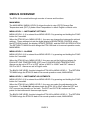
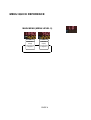
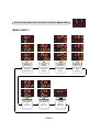
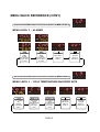
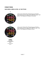
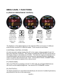
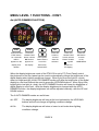
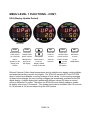
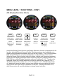
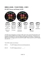
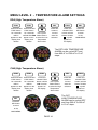
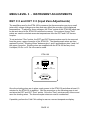
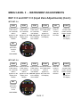
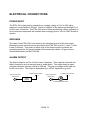
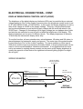
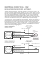
ETM-100
NON-TSO
ENGINE TEMPERATURE
MONITOR
USER'S MANUAL
Adaptive Interfaces, Inc.
2013
The ETM-100 is not certified by the FAA and is intended for use only in Homebuilt,
Experimental or Ultralight aircraft. Any questions pertaining to the use of this instrument
in a particular aircraft should be addressed to your local aviation authorities. It is the
responsibility of the aircraft pilot to be thoroughly familiar with the operation of the
ETM-100 and know its limitations. Correct installation of this instrument should be
verified by a qualified avionics facility.
TABLE OF CONTENTS
PAGE
INTRODUCTION
1
SCOPE
DESCRIPTION
SPECIFICATIONS
1
1
1
BUTTON FUNCTIONS
2
INDICATORS
2
MENUS OVERVIEW
3
MENUS QUICK REFERENCE
MAIN MENU (MENU 0) FUNCTIONS
F
C
MENU 1 FUNCTIONS
br (DISPLAY BRIGHTNESS CONTROL)
Ad (AUTO DIMMER FUNCTION)
UPd (Display Update Period)
rES (Display Resolution)
EG (EGT Sensor and Display On/Off)
CH (CHT Sensor and Display On/Off)
MENU 2 FUNCTIONS - ALARMS
EGT Alarm Settings
CHT Alarm Settings
MENU 3 FUNCTIONS - INSTRUMENT ADJUSTMENTS
Cold Cal - Ice Bath Temperature Setting
EGT C 0 and CHT C 0 - Thermocouple Input Zero Settings
SPECIAL FUNCTION
Lo E (LOW VOLTAGE WARNING) - SPECIAL FUNCTION
4-6
7
7
7
8
8
9
10
11
12
13
14
14
14
15
15
16 - 17
18
18
TABLE OF CONTENTS
(CONT.)
ELECTRICAL CONNECTIONS
POWER INPUT
GROUNDS
ALARM OUTPUT
DISPLAY BRIGHTNESS CONTROL INPUT
BACKLIGHT BRIGHTNESS CONTROL INPUT
CYLINDER HEAD TEMPERATURE - TYPE-J THERMOCOUPLE
EXHAUST GAS TEMPERATURE - TYPE-K THERMOCOUPLE
BACK PANEL DIAGRAM
19
19
19
19
20
21
22
23
APPENDIX A
INTRODUCTION
SCOPE
This manual provides specifications, operating instructions and installation
instructions for the ETM-100 Engine Temperature Monitor. This manual is for use
by persons who are familiar with aircraft, aircraft avionics, and general electronic
principles.
DESCRIPTION
The ETM-100 Engine Temperature Monitor is a solid state instrument that displays
Exhaust Gas Temperature (EGT) and Cylinder Head Temperature (CHT) on a
4-digit over 3-digit LED display. Temperatures can be displayed in english units
(Degrees Fahrenheit) or metric units (Degrees Celcius).
The ETM-100 uses thermocouples to measure EGT and CHT. A thermocouple is
a sensor made from two different metals that generates a voltage when heated.
The ETM-100 uses a single Type-J Thermocouple to measure CHT and a single
Type-K Thermocouple to measure EGT.
Control of the ETM-100 is by a set of 4 buttons on the front panel of the instrument.
The ETM-100 is a standard 2-1/4 inch instrument and is designed to be mounted
in a standard 2-1/4 inch aircraft panel cut-out. The display brightness and internal
backlighting can be controlled by the user.
SPECIFICATIONS
Supply Voltage:
Maximum Supply Current:
EGT Temperature Display Range:
EGT Temperature Accuracy:
CHT Temperature Display Range:
CHT Temperature Accuracy:
EGT Sensor Type:
CHT Sensor Type:
10 Vdc - 30 Vdc
350 mA
0 - 2000 Degrees F (-17 C - 1093 C)
+/- 20 Degrees F
0 - 1200 Degrees F (-17 C - 649 C)
+/- 20 Degrees F
Type K Thermocouple
Type J Themocouple
Dimensions:
Weight:
Mounting Screws:
Upper Connector:
Lower Connector:
H 2.40" x W 2.50" x D 1.50"
4 Oz. (114 g.)
4 ea. 6-32 x L 0.5" (Max.)
4-Pin Screw Terminal
9-Pin DSUB Female 4-40
PAGE 1
BUTTON FUNCTIONS
FUNC
This button is used to select and advance instrument functions for each
menu level. Holding this button in for 5 seconds will cause the instrument
to advance to the next menu level.
When the instrument is in the MAIN MENU mode, these buttons are used
to adjust the brightness of the digital display when the DISPLAY
BRIGHTNESS function is set to FP (Front Panel). Otherwise, in Main Menu
mode, these buttons perform no operations. In functions of MENU LEVEL 1,
MENU LEVEL 2 and MENU LEVEL 3, these buttons are used to select
options or to increase or decrease values of the selected function.
SEL
When the instrument is in the MAIN MENU mode, this button is used to
deactivate the instrument's ALARM for a period of 2 minutes.
In all other cases, the button is used as an "Enter" button to select and
retain the value or setting of the displayed function.
INDICATORS
F
The F indicator is lit when the instrument is displaying (EGT) Exhaust Gas
Temperature and (CHT) Cylinder Head Temperature in Degrees Fahrenheit
or English mode.
C
The C indicator is lit when the instrument is displaying (EGT) Exhaust Gas
Temperature and (CHT) Cylinder Head Temperature in Degrees Celcius or
Metric mode.
o
o
PAGE 2
MENUS OVERVIEW
The ETM-100 is controlled through a series of menus and functions.
MAIN MENU
The MAIN MENU (MENU LEVEL 0) allows the pilot to view (EGT) Exhaust Gas
Temperature and (CHT) Cylinder Head Temperature in either English or Metric units.
MENU LEVEL 1 - INSTRUMENT SETTINGS
MENU LEVEL 1 (L1) is entered from MENU LEVEL 0 by pressing and holding the FUNC
button for 5 seconds.
When the ETM-100 is in MENU LEVEL 1, the user can change the instrument's optional
settings. These settings include the digital display's BRIGHTNESS CONTROL mode,
the AUTO DIM function, the display UPDATE PERIOD, and the DISPLAY RESOLUTION.
The RETURN TO MAIN function brings the ETM-100 back to its normal operation mode,
MAIN MENU.
MENU LEVEL 2 - ALARMS
MENU LEVEL 2 (L2) is entered from MENU LEVEL 1 by pressing and holding the FUNC
button for 5 seconds.
When the ETM-100 is in MENU LEVEL 2, the user can set the high-level alarms for
EXHAUST GAS TEMPERATURE (EGT) and CYLINDER HEAD TEMPERATURE.
Alarms can be set to OFF or to EGT values of 800 F to 1900 F and CHT values of
500 F to 900 F. Alarms are set in English units.
The BACK ONE LEVEL function brings the ETM-100 to MENU LEVEL 1. The RETURN
TO MAIN brings the ETM-100 back to its normal operation mode, MAIN MENU.
MENU LEVEL 3 - INSTRUMENT ADJUSTMENTS
MENU LEVEL 3 (L3) is entered from MENU LEVEL 2 by pressing and holding the FUNC
button for 5 seconds.
When the ETM-100 is in MENU LEVEL 3, the user can make fine adjustments to the
instrument. The Cold CAL adjustment sets the ETM-100 to 32o F when the EGT and
CHT sensors are placed in an ice bath. The EGT and CHT C 0 functions set Zero
points for the instrument's thermocouple inputs.
The BACK ONE LEVEL function brings the ETM-100 to MENU LEVEL 2. The RETURN
TO MAIN brings the ETM-100 back to its normal operation mode, MAIN MENU.
PAGE 3
MENU QUICK REFERENCE
MAIN MENU (MENU LEVEL 0)
oF
oC
ENGLISH
METRIC
Display
Temperatures
in degrees F.
Display
Temperatures
in degrees C.
PAGE 4
Press and hold FUNC button 5 seconds to advance to MENU LEVEL 1
MENU LEVEL 1
Br
UPd
Ad
rES
DISPLAY
BRIGHTNESS
AUTO
DIMMER
UPDATE
FREQUENCY
DISPLAY
RESOLUTION
Change display
brightness
control mode.
Turn Auto Dim
function On
and Off.
Select display
update time
period.
Select display
digits
resolution.
EG
CH
EGT SENSOR
AND DISPLAY
CHT SENSOR
AND DISPLAY
RETURN
TO MAIN
Turn
ON or OFF.
Turn
ON or OFF.
Return to
Main Menu.
PAGE 5
MENU QUICK REFERENCE (CONT.)
Press and hold FUNC button 5 seconds to advance to MENU LEVEL 2
MENU LEVEL 2 - ALARMS
EGA
CHA
EGT HIGH
TEMP.
ALARM
Set High Alarm
level in deg. F
or to OFF.
CHT HIGH
TEMP.
ALARM
Set High Alarm
level in deg. F
or to OFF.
RETURN
ONE LEVEL
RETURN
TO MAIN
Return to
LEVEL 1
Return to
Main Menu.
Press and hold FUNC button 5 seconds to advance to MENU LEVEL 3
MENU LEVEL 3 - COLD TEMPERATURE AND ZERO SETS
Cold
(EGT) C O
(CHT) C O
32o F TEMP.
SET
EGT INPUT
ZERO
CALIBRATION
Set 0.0 V
EGT Input
Point.
CHT INPUT
ZERO
CALIBRATION
Set 0.0 V
CHT Input
Point.
Ice Bath
Temperature
Value.
PAGE 6
RETURN
ONE LEVEL
RETURN
TO MAIN
Return to
LEVEL 2
Return to
Main Menu.
FUNCTIONS
MAIN MENU (MENU LEVEL 0) FUNCTIONS
F
In this mode, Exhaust Gas Temperature and Cylinder
Head Temperature are displayed in ENGLISH units. EGT
and CHT are displayed in Degrees Fahrenheit.
C
In this mode, Exhaust Gas Temperature and Cylinder
Head Temperature are displayed in METRIC units. EGT
and CHT are displayed in Degrees Celcius.
FUNC
Press and release
FUNC
to change from
F to C
PAGE 7
MENU LEVEL 1 FUNCTIONS
br (DISPLAY BRIGHTNESS CONTROL)
FUNC
SEL
FUNC
SEL
Press and Hold
FUNC button
for 5 seconds
until L1, then br
appears on the
display, then
release.
Press SEL
button to
set and
store the
mode.
Press and
release FUNC
button until the
Return To Main
symbol
appears on
the display.
Press the
SEL button
to return
to the
MAIN MENU.
Use Up and
Down buttons
to select the
brightness
control mode.
The brightness of the digital display and the indicator LEDs can be set to 16 different
levels and be controlled in 3 different modes. These modes are as follows:
E (EXTERNAL CONTROL VOLTAGE)
An external control voltage ranging from 0V to the supply voltage is applied to pin 3 of
the Lower Electrical Connector. This voltage is sampled by the ETM-100 and its ratio to
the Supply Voltage is calculated into 16 levels. This allows a single potentiometer to be
connected between ground and the instrument power input and used as a brightness
control, its center tap used as the pin 3 input. See the ELECTRICAL CONNECTIONS
section of this manual for details of the control circuit.
FP (FRONT PANEL)
When the ETM-100 is operating in the ALT or MC mode, the UP and DOWN buttons
are used to set the display brightness. Also see the AUTO DIMMER function.
PH (PHOTOCELL)
The display brightness is controlled automatically by the amount of ambient light seen by
the photocell on the front of the instrument.
PAGE 8
MENU LEVEL 1 FUNCTIONS - CONT.
Ad (AUTO DIMMER FUNCTION)
FUNC
FUNC
SEL
FUNC
SEL
Press and Hold
FUNC button
for 5 seconds
until L1
appears on the
display, then
release.
Press and
release FUNC
button until the
Ad function
appears on
the display.
Press SEL
button to
set and
store the
selection.
Press and
release FUNC
button until the
Return To Main
symbol
appears on
the display.
Press the
SEL button
to return
to the
MAIN MENU.
Use Up and
Down buttons
to turn the
Ad function
ON and OFF.
When the display brightness mode of the ETM-100 is set to FP (Front Panel) control,
the photocell on the front panel can be used to automatically change the brightness of the
digital display when lighting conditions change. When flying from low light (ie. clouds,
dawn) to bright sunlight, the AUTO DIMMER function will raise the brightness of the digital
display to a set level without the need to press the UP/DOWN buttons. When flying from
bright light to low light (ie. dusk), the AUTO DIMMER function will lower the brightness of
digital display to a set level. After the display brightness is changed with the AUTO
DIMMER function, the display brightness can still be adjusted manually with the UP and
DOWN buttons.
The 2 AUTO DIMMER modes are as follows:
Ad OFF
The display brightness will stay at the level selected by the UP/DOWN
buttons and will not change as lighting conditions change.
Ad On
The display brightness will raise or lower to set levels when lighting
conditions change.
PAGE 9
MENU LEVEL 1 FUNCTIONS - CONT.
UPd (Display Update Period)
DEFAULT
FUNC
FUNC
SEL
FUNC
SEL
Press and Hold
FUNC button
for 5 seconds
until L1
appears on the
display, then
release.
Press and
release FUNC
button until the
UPd function
appears on
the display.
Press SEL
button to
set and
store the
selection.
Press and
release FUNC
button until the
Return To Main
symbol
appears on
the display.
Press the
SEL button
to return
to the
MAIN MENU.
Use Up and
Down buttons
to set the
Display Update
Period in seconds.
Exhaust Gas and Cylider Head temperatures tend to stabilize at a steady cruising altitude
and airspeed but they may still vary slightly. The ETM-100 samples EGT and CHT 250
times a second and displays a running average of their values. As the running averages
of these values change, the new running averages are immediately available to the LED
digital display. A digital display that updates with different values 250 times a second
can be a distraction to a pilot. Therefore, the ETM-100 has a default setting to update
its display once every 2.0 seconds. This update period can be modified from 0.5 seconds
to 5.0 seconds in 0.5 second steps using the UPd function.
PAGE 10
MENU LEVEL 1 FUNCTIONS - CONT.
rES (Display Resolution Select)
FUNC
FUNC
SEL
FUNC
SEL
Press and Hold
FUNC button
for 5 seconds
until L1
appears on the
display, then
release.
Press and
release FUNC
button until the
rES function
appears on
the display.
Press SEL
button to
set and
store the
selection.
Press and
release FUNC
button until the
Return To Main
symbol
appears on
the display.
Press the
SEL button
to return
to the
MAIN MENU.
Use Up and
Down buttons
to select the
diplay
resolution.
As with the Display Period function, the Display Resolution function compensates for the
fact that, although Exhaust Gas and Cylider Head temperatures tend to stabilize at a
steady cruising altitude and airspeed, they may still vary slightly. The ETM-100 samples
EGT and CHT 250 times a second and displays a running average of their values.
While the Display Period function limits the number of times new values are presented
to the pilot, the Display Resolution function limits the changes in displayed values. The
ETM-100 has a default Display Resolution setting of 5 degrees F or C. Therefore, the
displayed values only change when they increase or decrease by 5 degrees F or C.
The Display Resolution can be set to 1, 5 or 10 degrees F or C. A Display Resolution
of 1 degree will cause the display to show more precise values but values will tend to
change more often and may be a distraction to the pilot. A Display Resolution of 10,
while less precise, will cause the display to change values less often.
PAGE 11
MENU LEVEL 1 FUNCTIONS - CONT.
EG (EGT Sensor and Display On/Off)
FUNC
FUNC
SEL
FUNC
SEL
Press and Hold
FUNC button
for 5 seconds
until L1
appears on the
display, then
release.
Press and
release FUNC
button until the
EG function
appears on
the display.
Press SEL
button to
set and
store the
selection.
Press and
release FUNC
button until the
Return To Main
symbol
appears on
the display.
Press the
SEL button
to return
to the
MAIN MENU.
Use Up and
Down buttons
to turn the
EGT Sensor
ON and OFF.
The ETM-100 is designed to use both an EGT sensor and a CHT sensor but there may
be a case when an EGT sensor is either not used or non-functional. If a sensor is not
attached to the ETM-100, erronious readings will appear on the display. Therefore, the
EGT function and display can be turned off if needed. When turned off, the EGT display
will show as "_ _ _ _."
The 2 EGT modes are as follows:
EG On
The EGT display will show normal temperatures.
EG Off
The EGT display will show "_ _ _ _."
PAGE 12
MENU LEVEL 1 FUNCTIONS - CONT.
CH (CHT Sensor and Display On/Off)
FUNC
FUNC
SEL
FUNC
SEL
Press and Hold
FUNC button
for 5 seconds
until L1
appears on the
display, then
release.
Press and
release FUNC
button until the
CH function
appears on
the display.
Press SEL
button to
set and
store the
selection.
Press and
release FUNC
button until the
Return To Main
symbol
appears on
the display.
Press the
SEL button
to return
to the
MAIN MENU.
Use Up and
Down buttons
to turn the
CHT Sensor
ON and OFF.
The ETM-100 is designed to use both an EGT sensor and a CHT sensor but there may
be a case when a CHT sensor is either not used or non-functional. If a sensor is not
attached to the ETM-100, erronious readings will appear on the display. Therefore, the
CHT function and display can be turned off if needed. When turned off, the CHT display
will show as "_ _ _."
The 2 CHT modes are as follows:
CH On
The CHT display will show normal temperatures.
CH Off
The CHT display will show "_ _ _."
PAGE 13
MENU LEVEL 2 - TEMPERATURE ALARM SETTINGS
EGA (High Temperature Alarm)
FUNC
SEL
FUNC
SEL
Press and Hold Press and Hold
FUNC button
FUNC button
for 5 seconds
for 5 seconds
Use Up and
until L2 then EGA Down buttons
until L1
appears on the appear on the to select the Low
display, then
display, then
Temperature
release.
release.
Alarm value.
Press SEL
button to
set and
store the
selection.
Press and
release FUNC
button until the
Return To Main
symbol
appears on
the display.
Press the
SEL button
to return
to the
MAIN MENU.
FUNC
The EGT HIGH TEMPERATURE
ALARM can be cycled OFF and
from 800 o F to 1900 o F in 10 o F
steps.
CHA (High Temperature Alarm)
FUNC
FUNC
Press and Hold
FUNC button
for 5 seconds
until L1
appears on the
display, then
release.
Press and Hold
FUNC button
for 5 seconds
until L2
appears on the
display, then
release.
FUNC
Press and
release FUNC
button until the
Use Up and
CHA function
Down buttons
appears on
to select the High
the display.
Temperature
Alarm value.
SEL
FUNC
Press SEL
button to
set and
store the
selection.
Press and
release FUNC
button until the
Return To Main
symbol
appears on
the display.
The CHT
HIGH TEMPERATURE
ALARM can be cycled OFF
and from 500 o F to 900 o F
in 10 o F steps.
SEL
Press the
SEL button
to return
to the
MAIN MENU.
PAGE 14
MENU LEVEL 3 - INSTRUMENT ADJUSTMENTS
Cold Cal (Ice Bath Adjustment)
TO PERFORM THIS SETTING, BOTH
THERMOCOUPLES NEED TO BE
REMOVED FROM THE ENGINE AND
PLACED IN AN ICE BATH AT 32 o F.
THIS SETTING REQUIRES THAT BOTH
AN EGT (Type K) AND A CHT (Type J)
THERMOCOUPLE SENSOR BE
CONNECTED TO THE ETM-100.
When thermocouples are connected to the ETM-100, small voltages (microvolts) are
created at the connection points of the instrument. These voltages change with the
temperature of the ETM-100 in the panel of the cockpit and can affect the accuracy
of the EGT and CHT measurements. The ETM-100 has an internal temperature sensor
next to the thermocouple connector that is used to compensate for these voltages.
The Cold Cal adjustment allows the user to set the ETM-100 to a known, accurate
temperature so that engine temperatures can be displayed even when the engine is
cold. To make this setting, both the EGT and CHT thermocouple sensors must be
placed in an ice bath. An ice bath can be made by placing crushed ice, and a little
water, in an insulated cup. Once placed in the crushed ice, the thermocouples should
left for at least 10 minutes for their temperatures to stabilize.
FUNC
Press and Hold
FUNC button
for 5 seconds
until L1
appears on the
display, then
release.
FUNC
SEL
FUNC
SEL
Press SEL
button to
set and
store the
32 o F
calibration.
Press and
release FUNC
button until the
Return To Main
symbol
appears on
the display.
Press the
SEL button
to return
to the
MAIN MENU.
FUNC
Press and Hold Press and Hold
FUNC button
FUNC button
for 5 seconds
for 5 seconds
until L3 then
until L2
appears on the Cold CAL appears
on the display,
display, then
then release.
release.
PAGE 15
MENU LEVEL 3 - INSTRUMENT ADJUSTMENTS
EGT C 0 and CHT C 0 (Input Zero Adjustments)
The amplifiers used by the ETM-100 to measure the thermocouples may incur small
(microvolt) voltage changes over time that may affect the accuracy of the displayed
temperatures. To adjust for these voltages, the "Zero" points of the ETM-100 inputs can
be set and stored in the ETM-100's electronic memory. Once stored, these "Zero"
points are used to calculate accurate temperatures from the EGT and CHT thermocouples.
To set and store "Zero" points, the EGT and CHT thermocouples need to be removed
from the green, upper connector of the ETM-100. The thermocouple wires are then
replaced by short, "Shorting Wires" between pins 1 and 2 and between pins 3 and 4 of
the upper connector. Shorting wires are supplied with the ETM-100 but any short,
U-shaped, 20 Ga. or 22 Ga. wire can be used.
ETM-100
1 2 3 4
GND
GND
CHT
SHORTING WIRE
EGT
SHORTING WIRE
5 4 3 2 1
9 8 7 6
Once the shorting wires are in place, apply power to the ETM-100 and allow at least 10
minutes for the ETM-100 to stabilize. Use the procedure on the following page to set
and store the EGT and CHT "Zero" points. Once the "Zero" points are set, remove and
save the shorting wires. The thermocouple wires can now be re-attached.
If possible, perform the Cold CAL setting to assure a correct temperature display.
PAGE 16
MENU LEVEL 3 - INSTRUMENT ADJUSTMENTS
EGT C 0 and CHT C 0 (Input Zero Adjustments) (Cont.)
SET EGT C 0
FUNC
Press and Hold
FUNC button
for 5 seconds
until L1
appears on the
display, then
release.
FUNC
FUNC
FUNC
Press and Hold Press and Hold Press and release
FUNC button
FUNC button the FUNC button
until C 0
for 5 seconds
for 5 seconds
appears on
until L3 then
until L2
appears on the Cold CALappears the Upper LED
LED display.
on the display,
display, then
then release.
release.
SEL
FUNC
Press SEL
button to
set and
store the
EGT Zero.
Press and
release FUNC
button until the
Return To Main
symbol
appears on
the display.
SEL
FUNC
Press SEL
button to
set and
store the
selection.
Press and
release FUNC
button until the
Return To Main
symbol
appears on
the display.
SEL
Press the
SEL button
to return
to the
MAIN MENU.
SET CHT C 0
FUNC
Press and Hold
FUNC button
for 5 seconds
until L1
appears on the
display, then
release.
FUNC
FUNC
FUNC
Press and Hold Press and Hold Press and release
FUNC button
FUNC button the FUNC button
until C 0
for 5 seconds
for 5 seconds
appears
on
until L2
until L3 then
appears on the Cold CAL appears the Lower LED
on the display,
LED display.
display, then
release.
then release.
SEL
Press the
SEL button
to return
to the
MAIN MENU.
PAGE 17
SPECIAL FUNCTION
Lo E (Low Voltage Warning)
The ETM-100 is designed to operate from a supply voltage of 10V to 30V. Most aircraft
operate on a 12V electrical system (voltage is typically around 14V). When the supply
voltage to the ETM-100 drops to 11V or lower, the instruments digital display will flash
"Lo E" for 1 second every 8 seconds. This function is designed to give a pilot warning
that there may be a problem with the aircraft's electrical system. The "Lo E" function is
hardwired into the design of the instrument an can not be disabled.
PAGE 18
ELECTRICAL CONNECTIONS
POWER INPUT
The ETM-100 is designed to operate from a supply voltage of 10V to 30V with a
maximum current draw of 350 mA. Power is supplied to the instrument through Pin-9
of the Lower Connector. The ETM-100 uses an internal switching voltage regulator so
so no external components are needed when changing from a 12V to a 28V electrical
system.
GROUNDS
The case of the ETM-100 is connected to the electrical ground of the instrument.
Electrical ground connections are provided to the ETM-100 on pins 5, 6 and 7 of the
Lower Connector. Two posts on either side of the thermocouple connector are
grounding points for the ground shields of thermocouple cables. All grounds are
connected internally on the ETM-100.
ALARM OUTPUT
The Alarm Output is on Pin-8 of the Lower Connector. This output is used with the
Alarm function to drive a warning lamp or audio alarm. The output uses an open
collector transistor that can sink up to 300 mA. The pull-up voltage of the load can
be 40 Vdc or less. The output is decoupled by a 100 pF capacitor to ground.
FUSED SUPPLY BUSS
FUSED SUPPLY BUSS
LOWER CONNECTOR
+V
ALRM PIN-8
LOWER CONNECTOR
ALRM PIN-8
AUDIO
BUZZER
ALARM INDICATOR LAMP
PAGE 19
+V
ELECTRICAL CONNECTIONS - CONT.
DISPLAY BRIGHTNESS CONTROL INPUT (VDISP)
The brightness of the digital display and indicator LEDs can be contolled by an external
voltage applied to Pin-3 of the Lower Connector when the brightness control mode is set
to "E" (See MENU LEVEL 1 FUNCTIONS). In this mode, the display brightness is set by
ratio of the voltage at VDISP to the Supply Voltage. This way, a single potentiometer
can be placed between ground and the supply voltage with its center tap wired to the
VDISP input. Changes or fluctuations of the supply voltage (as can happen when lights
and avionics are switched on and off) will not affect the brightness of the display. The
display brightness can be set to 16 different levels. The display brightness is limited to
16 levels by the instrument's display driver chip.
To use this function, a linear potentiometer, valued between 10k ohms and 20k ohms, is
placed between the instrument supply and ground. The center tap of the potentiometer
is wired directly to Pin-3 of the Lower Connector. The input resistance of this input is
200k ohms and the input is protected by Schottky diodes. A single potentiometer can be
used to control several Adaptive Interfaces instruments. It is suggested that this input
not be connected to existing dimmer controls on the panel as the display brightness is
usually the opposite of that desired for nighttime instrument lighting (bright in sunlight dim at night).
WIRING EXAMPLE
TO PIN-3 OF OTHER
ADAPTIVE INTERFACES
INSTRUMENTS
FUSED SUPPLY BUSS
+V
+ SUPPLY
LOWER CONNECTOR PIN-9
10k OHM
POTENTIOMETER
CW
VDISP
LOWER CONNECTOR PIN-3
TAP
ETM-100
GND
UPPER CONNECTOR PIN-4, PINS 8-15
LOWER CONNECTOR PIN-5, PIN-6, PIN-7
CCW
DISPLAY
BRIGHTNESS
PAGE 20
ELECTRICAL CONNECTIONS - CONT.
BACKLIGHT BRIGHTNESS CONTROL INPUT (VBKLT)
The ETM-100 has an integrated, white LED, backlight for its front panel graphics. The
only way to control the brightness of the backlight is to apply a control voltage to Pin-4 of
the Lower Connector (VBKLT). The backlight brightness can be set to 256 levels by the
ratio of the voltage at VBKLT to the Supply Voltage. This way, a single potentiometer
can be placed between ground and the supply voltage with its center tap wired to the
VBKLT input. Changes or fluctuations of the supply voltage (as can happen when lights
and avionics are switched on and off) will not affect the brightness of the backlight.
To use this function, a linear potentiometer, valued between 10k ohms and 20k ohms, is
placed between the instrument supply and ground. The center tap of the potentiometer
is wired directly to Pin-4 of the Lower Connector. The input resistance of this input is
200k ohms and the input is protected by Schottky diodes. A single potentiometer can be
used to control several Adaptive Interfaces instruments. The VBKLT input can also be
wired into the existing panel lighting circuit.
TO PIN-4 OF OTHER
ADAPTIVE INTERFACES
INSTRUMENTS
WIRING EXAMPLE 1
SEPARATE CONTROL
FUSED SUPPLY BUSS
+V
10k OHM
+ SUPPLY
LOWER CONNECTOR PIN-9
POTENTIOMETER
CW
VBKLT
LOWER CONNECTOR PIN-4
TAP
ETM-100
GND
UPPER CONNECTOR PIN-4, PINS 8-15
LOWER CONNECTOR PIN-5, PIN-6, PIN-7
CCW
BACKLIGHT
BRIGHTNESS
TO PIN-4 OF OTHER
ADAPTIVE INTERFACES
INSTRUMENTS
WIRING EXAMPLE 2
EXISTING PANEL LIGHTING
FUSED SUPPLY BUSS
+V
EXISTING DIMMER CIRCUIT
+ SUPPLY
LOWER CONNECTOR PIN-9
EXISTING PANEL LAMPS
VBKLT
LOWER CONNECTOR PIN-4
ETM-100
GND
UPPER CONNECTOR PIN-4, PINS 8-15
LOWER CONNECTOR PIN-5, PIN-6, PIN-7
PAGE 21
ELECTRICAL CONNECTIONS - CONT.
CYLINDER HEAD TEMPERATURE (CHT) - TYPE J THERMOCOUPLE
The ETM-100 is designed to use a Type J Thermocouple to measure Cylinder Head
Temperature. Type J Thermocouples use Red (-) and White (+) wires and may or may
not have a ground shield (usually a braided wire covering). If the Type J Thermocouple
has a ground shield, it can be connected to the Ground post next to the green, Upper
Connector.
Most thermocouples are isolated from Ground (Engine Block and Aircraft Frame) but
some may have the negative (Red) wire connected to Ground. The ETM-100 will work
with both types of thermocouple.
TO FUSED SUPPLY BUSS
+ SUPPLY
LOWER CONNECTOR PIN-9
TYPE J THERMOCOUPLE
CHT - (RED WIRE)
UPPER CONNECTOR PIN-1
CHT + (WHITE WIRE)
UPPER CONNECTOR PIN-2
ETM-100
GROUND SHIELD
GROUND POST
CHT
GND
LOWER CONNECTOR PIN-5, PIN-6, PIN-7
PAGE 22
ELECTRICAL CONNECTIONS - CONT.
EXHAUST GAS TEMPERATURE (EGT) - TYPE K THERMOCOUPLE
The ETM-100 is designed to use a Type K Thermocouple to measure Exhaust Gas
Temperature. Type K Thermocouples use Red (-) and Yellow (+) wires and may or may
not have a ground shield (usually a braided wire covering). If the Type K Thermocouple
has a ground shield, it can be connected to the Ground post next to the green, Upper
Connector.
Most thermocouples are isolated from Ground (Engine Block and Aircraft Frame) but
some may have the negative (Red) wire connected to Ground. The ETM-100 will work
with both types of thermocouple.
TO FUSED SUPPLY BUSS
+ SUPPLY
LOWER CONNECTOR PIN-9
TYPE K THERMOCOUPLE
CHT - (RED WIRE)
UPPER CONNECTOR PIN-3
CHT + (YELLOW WIRE)
UPPER CONNECTOR PIN-4
ETM-100
GROUND SHIELD
GROUND POST
EGT
GND
LOWER CONNECTOR PIN-5, PIN-6, PIN-7
PAGE 23
ETM-100 BACK PANEL
UPPER CONNECTOR
THERMOCOUPLE INPUTS
1) CHT - INPUT
RED WIRE
2) CHT + INPUT
WHITE WIRE
3) EGT - INPUT
RED WIRE
TYPE J THEROCOUPLE
4) EGT + INPUT
YELLOW WIRE
TYPE K THEROCOUPLE
1 2 3 4
GND
GND
CHT EGT
5 4 3 2 1
9 8 7 6
LOWER CONNECTOR
1) N/C
2) N/C
3) VDISP (DISPLAY BRIGHTNESS CONTROL VOLTAGE INPUT)
4) VBKLT (BACKLIGHT BRIGHTNESS CONTROL VOLTAGE INPUT)
5) GND (GROUND)
6) GND (GROUND)
7) GND (GROUND)
8) ALRM (ALARM OUTPUT - OPEN COLLECTOR)
9) + POWER INPUT
APPENDIX A