1
“MICRO” ADJUSTABLE SPEED DRIVE INTERFACE
DEVICENET COMMUNICATIONS INTERFACE
FOR THE TOSHIBA S7 SERIES
ADJUSTABLE SPEED DRIVE
September, 2002
ICC #10290-002
Introduction
Thank you for purchasing the External DeviceNet Communications Interface for the
Toshiba S7 Series Micro Adjustable Speed Drive. Before using the DeviceNet
interface, please familiarize yourself with the product and be sure to thoroughly read
the instructions and precautions contained in this manual. In addition, please make
sure that this instruction manual is delivered to the end user of the drive units with
which the DeviceNet interface is connected, and keep this instruction manual in a
safe place for future reference or drive/interface inspection.
This instruction manual describes the device specifications, wiring methods,
maintenance procedures, supported functions and usage methods for the external
DeviceNet communications interface.
In conjunction with this manual, the following manuals are supplied by Toshiba, and
are essential both for ensuring a safe, reliable system installation as well as for
realizing the full potential of the DeviceNet interface:
•
•
TOSVERT VF-S7 Series Instruction Manual
VF-S7 Industrial Inverter Serial Communications Option Manual
If you do not have copies of these documents available, please contact Toshiba or
your local Toshiba distributor to obtain them, or copies may be downloaded via the
internet from http://www.tic.toshiba.com.
Before continuing, please take a moment to ensure that you have received all
materials shipped with your kit. These items are:
•
•
•
External DeviceNet interface in DIN rail mountable case
2 meter DB9-RJ45 MMI port cable
This manual
1
• Usage Precautions
Operating Environment
•
Please use the DeviceNet interface only when the ambient temperature of the
environment into which the interface is installed is within the following specified
temperature limits:
Operation: -10 ∼ +40°C (+14 ∼ +104°F)
-25 ∼ +65°C (-13 ∼ +149°F)
Storage:
•
•
Avoid installation locations that may be subjected to large shocks or vibrations.
Avoid installation locations that may be subjected to rapid changes in temperature or
humidity.
Installation • Wiring
•
•
•
•
•
•
Do not touch charged parts of the drive such as the terminal block while the drive’s
CHARGE lamp is lit. A charge will still be present in the drive’s internal electrolytic
capacitors, and therefore touching these areas may result in an electrical shock.
Always turn all drive input power supplies OFF, and wait at least 5 minutes after the
CHARGE lamp has gone out before connecting communication cables or motor wiring.
Proper ground connections are vital for both safety and signal reliability reasons. For
proper grounding procedures, please refer to the ASD instruction manual for drive
considerations and the ODVA DeviceNet Specifications for network considerations.
Route all communication cables separate from drive input/output power wiring.
To avoid the possibility of electric shock due to leakage currents, always ground the
drive’s E/GND terminal and the motor. To avoid misoperation, do not connect the
DeviceNet network SHIELD terminal directly to either of the above-mentioned grounds
or any other power ground.
When making connections between the DeviceNet interface and the drives, do not use
cables that exceed 5 meters in length.
For further drive-specific precaution, safety and installation information, please refer to
the appropriate Toshiba documentation supplied with your drive.
Other Precautions
•
•
•
•
Do not touch or insert a rod or any other item into the DeviceNet interface’s case while
power is applied, as this may lead to electrical shock or device damage.
Commission the disposal of the DeviceNet interface to a specialist.
Do not assign the same MAC ID to more than one DeviceNet unit in the same network.
For an explanation of station addressing, refer to section 8.
Because the DeviceNet interface derives its control power from the DeviceNet network
power supply, removing network power or unplugging the network connector from the
unit will also cause the DeviceNet interface to lose power, even if power is still applied
to the connected drives.
2
TABLE OF CONTENTS
1.
Mechanical Diagrams ...........................................................................5
1.1
1.2
Enclosure .........................................................................................................5
Mounting Clip ...................................................................................................6
2.
General Specifications .........................................................................7
3.
Installing the Interface..........................................................................9
4.
Grounding............................................................................................11
5.
Environmental Specifications............................................................11
6.
Maintenance And Inspection .............................................................12
7.
Storage And Warranty ........................................................................13
7.1
7.2
Storage ..........................................................................................................13
Warranty ........................................................................................................13
8.
Configuration Switches......................................................................14
9.
Connection Information......................................................................16
9.1
9.2
Connection Sizes ...........................................................................................16
I/O Assembly Instances..................................................................................16
10.
Object Specifications .........................................................................17
10.1
Identity Object.............................................................................................18
10.1.1 Identity Object Class Attributes ...............................................................18
10.1.2 Identity Object Instance Attributes...........................................................18
10.1.3 Identity Object Common Services ...........................................................19
10.1.4 Identity Object Specific Services .............................................................19
10.2
Message Router .........................................................................................20
10.2.1 Message Router Class Attributes ............................................................20
10.2.2 Message Router Instance Attributes .......................................................20
10.2.3 Message Router Common Services ........................................................20
10.2.4 Message Router Specific Services ..........................................................20
10.3
DeviceNet Object........................................................................................21
10.3.1 DeviceNet Object Class Attributes ..........................................................21
10.3.2 DeviceNet Object Instance Attributes ......................................................21
10.3.3 DeviceNet Object Common Services ......................................................22
10.3.4 DeviceNet Object Specific Services ........................................................22
10.4
Assembly Object.........................................................................................23
10.4.1 Assembly Object Class Attributes ...........................................................23
10.4.2 Assembly Object Instance Attributes.......................................................23
3
10.4.3
10.4.4
10.4.5
10.4.5.1
10.4.5.2
Assembly Object Common Services .......................................................23
Assembly Object Specific Services .........................................................23
Assembly Instance Details ......................................................................24
Output Instance 100 (ASD Command) ........................................................................................ 24
Input Instance 150 (ASD Status) ................................................................................................. 26
10.5
Connection class ........................................................................................28
10.5.1 Connection Class Attributes ....................................................................28
10.5.2 Connection Class Instance Attributes......................................................28
10.5.2.1
10.5.2.2
Master/Slave Explicit Messaging Connection Object Instance Attributes ................................... 29
Poll Connection Object Instance Attributes ................................................................................. 30
10.5.3 Connection Class Common Services ......................................................31
10.5.4 Connection Class Specific Services ........................................................31
10.6
Parameter Class.........................................................................................32
11.
MMI Port Use....................................................................................... 33
12.
Notes ................................................................................................... 34
4
1. Mechanical Diagrams
1.1 Enclosure
(All units are in inches)
5
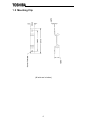
1.2 Mounting Clip
(All units are in inches)
6
2. General Specifications
Application
Toshiba 7-Series ASDs, externally mounted
Terminations
One 5-pin pluggable gold-plated connector for DeviceNet bus connection.
Two RJ45 jacks (TTL-level) for connection to ASDs
One RJ45 jack (RS232-level) for MMI port connection
Control Power Supply
SOURCE ....................................Supplied by DeviceNet network
VOLTAGE RANGE .....................11 ∼ 25 VDC
LED Indicators
One bicolor red/green Module Status LED
• Behavior according to ODVA DeviceNet Specifications
One bicolor red/green Network Status LED
• Behavior according to ODVA DeviceNet Specifications
One green LED on Channel A and Channel B interface ports
• Indicates local isolated circuitry power is being received from connected drive
One green LED on MMI interface port
• Context is application-specific, but under normal operation used as a 1-Hz
“heartbeat” indicator
• When used with FlashLoader programming utility, indicates data transfer
• Upon interface initialization after a reset, heartbeat indicator will not begin
until the unit has achieved the “on-line / unconnected” state
Compatibility
Group 2 Server Only device utilizing the Predefined Master / Slave Connection Set.
Vendor-specific I/O POLL connection (8 bytes of data consumed and 8 bytes of data
produced). This product has been self-tested by Toshiba International Corporation
and found to comply with ODVA Conformance Test Software Version A-13.
Node Isolation
Each connected ASD is fully optically isolated from the control/network portion and
from each other at the physical layer. This eliminates grounding differential problems
and greatly improves noise immunity characteristics.
7
Bus Interface
Phillips 82C251 or equivalent transceiver.
Drive Connections
Provides support for simultaneous connection of two 7-series ASDs. Both drives
share a common DeviceNet MAC ID. By supporting 2 drives per interface, the
maximum number of drives that can be connected to 1 network segment increases
from 63 (63 drives + 1 master) to 126 (63 external DeviceNet units + 1 master).
Uses standard RJ-45 style 8-pin modular connectors. Any standard category-5
ethernet cable (found in most electronics stores) 5 meters or less in length can be
used to connect the DeviceNet interface to the drives.
Drive AutoScan Algorithm
Connections to the drives are automatically established and continuously monitored.
No drive configuration needs to be performed to connect the DeviceNet interface and
communicate via the DeviceNet network. Just plug it in – it’s that simple.
Versatile 3-Way DIN-Rail Mounting System
The interface unit enclosure is provided with a mounting clip attached to the rear of
the unit. This clip allows the unit to be mounted 3 different ways:
•
For DIN rail mounting, snap the mounting clip onto a standard DIN rail, and
then snap the unit enclosure onto the clip’s retaining tabs. This allows easy
removal or repositioning of the unit on the DIN rail during wiring.
•
For panel mounting, the mounting clip can be bolted directly to a flat panel via
the two bolt holes at the top and bottom of the clip. Refer to section 1.2 for
mounting clip mechanical details. Once the mounting clip is securely
attached to the panel, the unit enclosure can be snapped onto the clip’s
retaining tabs.
•
For fixed DIN rail mounting, a combination of the above two techniques can
be employed. First, snap the mounting clip onto a DIN rail and position it in its
desired location. Then, the mounting clip can be bolted to the DIN rail support
panel, securing it in place. Lastly, the unit can be snapped onto the fixed
mounting clip.
In all cases, the unit can be easily unsnapped from the mounting clip to temporarily
provide easier access to the configuration switches or network terminal block.
8
3. Installing the Interface
The DeviceNet Interface connects to each drive via the drive’s communication port,
located on either the right-hand side or the front of the drive enclosure (depending on
drive series) under a small snap-on cover. Although no drive parameters need to be
configured in order to use the DeviceNet interface, it is advantageous to check that
the drive’s communication data rate is set to its maximum speed. Because the
interface will communicate to each drive only at the drive’s configured data rate, this
will provide the fastest response time for drive-to-network data transfers. For
information on checking the drive’s communication data rate, refer to the appropriate
manual supplied with your drive. Note that this drive communication data rate setting
is independent of the DeviceNet network data rate, which is configured solely by the
interface’s “Configuration” DIP switches on the bottom of the unit. Also note that the
data communication parameters of each drive are handled independently; the drive
connected to “Channel A” may simultaneously communicate to the DeviceNet
interface at completely different baud rates, parity settings, etc. from the drive
connected to “Channel B”.
Installation of the External DeviceNet Interface should only be performed by a
qualified technician familiar with the maintenance and operation of the connected
drives. To install the unit, complete the following steps:
CAUTION!
1.
Verify that all input power sources to the drives to be
connected have been turned OFF and are locked and tagged out.
2.
Wait at least 5 minutes for the drive’s electrolytic
capacitors to discharge before proceeding to the next step. Do not touch any
internal parts with power applied to the drive, or for at least 5 minutes after
power to the drive has been removed. A hazard exists temporarily for
electrical shock even if the source power has been removed. Verify that the
CHARGE LED has gone out before continuing the installation process.
DANGER!
3. Attach the mounting clip and unit enclosure in your desired manner (refer to page
8 for more information).
4. Remove the drive’s communication port cover, located on the right-hand side of
the drive (as viewed when facing the drive) or on the front of the drive (location
depends on specific drive series). Do not discard this cover, as it should be
reinstalled if the DeviceNet interface is ever disconnected from the drive to
minimize contamination of the port’s electrical contacts.
5. Connect the communication port(s) of the drive(s) to “Channel A” and/or “Channel
B” on the front of the DeviceNet unit. If only one drive is to be connected to the
unit, it can be connected to either channel. The DeviceNet interface ships from
the factory with dust covers in place on both Channel B and the MMI port. To
minimize contamination to the port electrical contacts, keep these dust covers in
place whenever a particular port is not in use.
The communication cable(s) to connect the drive(s) to the DeviceNet interface
are not included with the interface kit. When choosing cables for this connection,
standard 24 AWG category-5 (CAT 5) shielded or unshielded twisted-pair (UTP)
8-conductor cables found in ethernet networks in most office environments can
9
be used. The maximum allowable length for these cables is 5 meters. Although
there are many varieties and styles of CAT-5 ethernet cables available, Toshiba
strongly recommends using only high-quality cables from reputable
manufacturers to guarantee optimal noise immunity, cable reliability and cable
longevity. Ensure that each end of the cable is fully seated into the modular
connectors, and route the cable such that it is located well away from any drive
input power or motor wiring. Also take care to route the cable away from any
sharp edges or positions where it may be pinched.
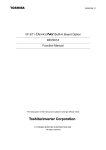
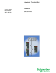
6. Connect the DeviceNet network cable to the pluggable “Network” terminal block
located on the bottom of the unit. Refer to Figure 1 for specific connector
positions. Be sure to follow all cabling, grounding and termination requirements
as outlined in the ODVA DeviceNet Specifications. Ensure that the network cable
wires are tightly screwed into the terminal block, and route the cable such that it
is located well away from any drive input power or motor wiring. Also take care to
route the cable away from any sharp edges or positions where it may be pinched.
V+
CAH H
SHIELD
CAN_L
V-
Figure 1: DeviceNet Network Wiring Connections
7. Take a moment to verify that the DeviceNet interface and all network cables have
sufficient clearance from drives, motors, or power-carrying electrical wiring.
8. Turn the power sources to all connected drives ON, and verify that the drives
function properly. If the drives do not appear to power up, or do not function
properly, immediately turn power OFF. Repeat steps 1 and 2 to remove all
power from the drives. Then, verify all connections. Contact Toshiba or your
local drive distributor for assistance if the problem persists.
10
4. Grounding
Grounding is of particular importance for reliable, stable operation. Communication
system characteristics may vary from system to system, depending on the system
environment and grounding method used. In general, however, the following
grounding checkpoints should be noted when connecting any communications
system to adjustable speed drives:
Grounding method checkpoints
1. Make all ground connections such that no ground current flows through the case
or heatsink of a connected drive.
2. Do not connect the DeviceNet network SHIELD to a power ground or any other
potential noise-producing ground connection (such as a drive’s “E” terminal).
3. Do not make connections to unstable grounds (paint-coated screw heads,
grounds that are subjected to inductive noise, etc.)
For specific requirements regarding protective grounding and the DeviceNet network,
refer to the ODVA DeviceNet Specifications.
5. Environmental Specifications
Item
Operating Environment
Operating Temperature
Storage Temperature
Relative Humidity
Vibration
Grounding
Cooling Method
Specification
Indoors, less than 1000m above sea level, do not
expose to direct sunlight or corrosive / explosive gasses
-10 ∼ +40°C (+14 ∼ +104°F)
-25°C ∼ +65°C (-13 ∼ +149°F)
20% ∼ 90% (without condensation)
5.9m/s2 {0.6G} or less (10 ∼ 55Hz)
Refer to ODVA DeviceNet Specifications
Self-cooled
11
6. Maintenance And Inspection
Preventive maintenance and inspection is required to maintain the external
DeviceNet interface in its optimal condition, and to ensure a long operational lifetime.
Depending on usage and operating conditions, perform a periodic inspection once
every three to six months. Before starting inspections, always turn off all power
supplies to the network and connected drives, and wait at least five minutes after
each drive’s “CHARGE” lamp has gone out.
DANGER!
Do not touch any internal parts with power applied
to the drives, or for at least 5 minutes after power to the drives has been
removed. A hazard exists temporarily for electrical shock even if the source
power has been removed.
Inspection Points
•
Check that the network connector screw terminals are not loose. Tighten if
necessary.
•
Check that the drive communication cables are not loose. Reinsert if necessary.
•
Check that there are no defects in any attached grounding wire terminal crimp
points. Visually check that the crimp points are not scarred by overheating.
•
Visually check all wiring and cables for damage. Replace as necessary.
•
Clean off any accumulated dust and dirt.
•
If use of the DeviceNet interface is discontinued for extended periods of time,
apply power at least once every two years and confirm that the unit still functions
properly.
•
Do not perform hi-pot tests on the drives or DeviceNet interface, as they may
damage the units.
Please pay close attention to all periodic inspection points and maintain a good
operating environment.
12
7. Storage And Warranty
7.1 Storage
Observe the following points when the DeviceNet interface is not used immediately
after purchase or when it is not used for an extended period of time.
•
Avoid storing the interface unit in places that are hot or humid, or that contain
large quantities of dust or metallic dust. Store the interface unit in a wellventilated location.
•
When not using the interface unit for an extended period of time, apply power at
least once every two years and confirm that it still functions properly.
7.2 Warranty
The Toshiba External DeviceNet Communications Interface is covered under
warranty by Toshiba International Corporation for a period of 12 months from the
date of installation, but not to exceed 18 months from the date of shipment from the
factory. For further warranty or service information, please contact Toshiba
International Corporation or your local distributor.
13
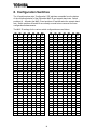
8. Configuration Switches
The 10-position piano-style “Configuration” DIP switches accessible from the bottom
of the unit allow selection of the DeviceNet MAC ID and network baud rate. Switch
positions #1 ∼ #6 select the MAC ID and positions #7 and #8 select the network baud
rate. Switch positions #9 and #10 are currently unused but are reserved for future
configuration enhancements.
The MAC ID settings for the various switch configurations are as follows:
SW
1
SW
2
SW
3
SW
4
SW
5
SW
6
MAC
ID
SW
1
SW
2
SW
3
SW
4
SW
5
SW
6
MAC
ID
OFF
OFF
OFF
OFF
OFF
OFF
0
OFF
OFF
OFF
OFF
OFF
ON
32
ON
OFF
OFF
OFF
OFF
OFF
1
ON
OFF
OFF
OFF
OFF
ON
33
OFF
ON
OFF
OFF
OFF
OFF
2
OFF
ON
OFF
OFF
OFF
ON
34
ON
ON
OFF
OFF
OFF
OFF
3
ON
ON
OFF
OFF
OFF
ON
35
OFF
OFF
ON
OFF
OFF
OFF
4
OFF
OFF
ON
OFF
OFF
ON
36
ON
OFF
ON
OFF
OFF
OFF
5
ON
OFF
ON
OFF
OFF
ON
37
OFF
ON
ON
OFF
OFF
OFF
6
OFF
ON
ON
OFF
OFF
ON
38
ON
ON
ON
OFF
OFF
OFF
7
ON
ON
ON
OFF
OFF
ON
39
OFF
OFF
OFF
ON
OFF
OFF
8
OFF
OFF
OFF
ON
OFF
ON
40
ON
OFF
OFF
ON
OFF
OFF
9
ON
OFF
OFF
ON
OFF
ON
41
OFF
ON
OFF
ON
OFF
OFF
10
OFF
ON
OFF
ON
OFF
ON
42
ON
ON
OFF
ON
OFF
OFF
11
ON
ON
OFF
ON
OFF
ON
43
OFF
OFF
ON
ON
OFF
OFF
12
OFF
OFF
ON
ON
OFF
ON
44
ON
OFF
ON
ON
OFF
OFF
13
ON
OFF
ON
ON
OFF
ON
45
OFF
ON
ON
ON
OFF
OFF
14
OFF
ON
ON
ON
OFF
ON
46
ON
ON
ON
ON
OFF
OFF
15
ON
ON
ON
ON
OFF
ON
47
OFF
OFF
OFF
OFF
ON
OFF
16
OFF
OFF
OFF
OFF
ON
ON
48
ON
OFF
OFF
OFF
ON
OFF
17
ON
OFF
OFF
OFF
ON
ON
49
OFF
ON
OFF
OFF
ON
OFF
18
OFF
ON
OFF
OFF
ON
ON
50
ON
ON
OFF
OFF
ON
OFF
19
ON
ON
OFF
OFF
ON
ON
51
OFF
OFF
ON
OFF
ON
OFF
20
OFF
OFF
ON
OFF
ON
ON
52
ON
OFF
ON
OFF
ON
OFF
21
ON
OFF
ON
OFF
ON
ON
53
OFF
ON
ON
OFF
ON
OFF
22
OFF
ON
ON
OFF
ON
ON
54
ON
ON
ON
OFF
ON
OFF
23
ON
ON
ON
OFF
ON
ON
55
OFF
OFF
OFF
ON
ON
OFF
24
OFF
OFF
OFF
ON
ON
ON
56
ON
OFF
OFF
ON
ON
OFF
25
ON
OFF
OFF
ON
ON
ON
57
OFF
ON
OFF
ON
ON
OFF
26
OFF
ON
OFF
ON
ON
ON
58
ON
ON
OFF
ON
ON
OFF
27
ON
ON
OFF
ON
ON
ON
59
OFF
OFF
ON
ON
ON
OFF
28
OFF
OFF
ON
ON
ON
ON
60
ON
OFF
ON
ON
ON
OFF
29
ON
OFF
ON
ON
ON
ON
61
OFF
ON
ON
ON
ON
OFF
30
OFF
ON
ON
ON
ON
ON
62
ON
ON
ON
ON
ON
OFF
31
ON
ON
ON
ON
ON
ON
63
14
The network baud rate settings are configured as follows:
SW7
SW8
Network Baud Rate
OFF
OFF
125 kbps
ON
OFF
250 kbps
OFF
ON
500 kbps
ON
ON
Invalid selection (DO NOT SELECT: this setting used
for factory production testing only)
Note that the “ON” position of each switch is the “down” position and that the “OFF”
position is the “up” position. Refer to the indicator markings on the switch.
The MAC ID and configured baud rate are read by the DeviceNet unit only on powerup or after a reset. Therefore, if either of these selections are changed be sure to
either power the unit off momentarily by disconnecting it from the network power
supply, or reset the unit by issuing a RESET service to the Identity Object (refer to
section 10.1.4 on page 19).
15
9. Connection Information
9.1 Connection Sizes
Connection
Instance
Polled I/O
Explicit Messaging
Produced
Consumed
8 bytes
40 bytes
8 bytes
40 bytes
Notes
• For the Explicit Messaging connection, this is the maximum message length:
shorter messages are also acceptable.
•
For the Polled I/O connection, if the actual consumed data size is less than
the connection instance’s consumed_connection_size attribute, the consumed
data will be ignored, but the connection will otherwise produce normally. If the
actual consumed data size is larger than the connection instance’s
consumed_connection_size attribute, the consumed data will be ignored and
the connection will not produce.
9.2 I/O Assembly Instances
The following table indicates which polled I/O assembly instances are currently
supported by the External DeviceNet Interface:
Number
Decimal
Hex
100
150
0x64
0x96
Name
Type
Output
Input
Toshiba-Specific Control Output
Toshiba-Specific Status Input
For more detailed information about these assembly instances, refer to section
10.4.5.
16
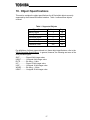
10. Object Specifications
This section contains the object specifications for all DeviceNet objects currently
supported by the External DeviceNet Interface. Table 1 outlines those objects
covered:
Table 1: Supported Objects
Object Class
Identity Object
Message Router
DeviceNet Object
Assembly Object
Connection class
Parameter Class
# of Instances
Page
1
1
1
2
2
281
18
20
21
23
28
32
For definitions of all data types referred to in these object specifications, refer to the
ODVA DeviceNet Specifications. In general, however, the following are some of the
most prevalent types:
SINT ..............Signed 8-bit integer value
USINT............Unsigned 8-bit integer value
BYTE .............Bit string – 8-bits
INT.................Signed 16-bit integer value
UINT ..............Unsigned 16-bit integer value
WORD ...........Bit string – 16-bits
UDINT............Unsigned 32-bit integer value
17
10.1 Identity Object
Class code 0x01. This object provides identification of and general information about
the device.
10.1.1 Identity Object Class Attributes
Attribute
ID
Access
Rules
Name
Data
Type
1
Get
Revision
UINT
Get
Max
Instance
UINT
Get
Max ID
number
of class
attributes
UINT
Get
Max ID
number
of
instance
attributes
UINT
2
6
7
Description
Revision of this object
Maximum instance
number of an object
currently created in this
class level of the device
The attribute ID of the
last class attribute of the
class definition
implemented in the
device
The attribute ID of the
last instance attribute of
the class definition
implemented in the
device
Default
Value
1
1
7
8
10.1.2 Identity Object Instance Attributes
Attribute
ID
Access
Rules
Name
Data
Type
Description
Default
Value
1
Get
Vendor
UINT
Identification of vendor
by number
71
2
Get
Device
Type
UINT
3
Get
4
Get
Indication of general
type of product
Identification of a
Product
UINT
particular product of
Code
an individual vendor
Revision of the item
STRUCT
Revision
the Identity Object
of:
represents
Major
USINT
Revision
Minor
Revision
USINT
18
12
50
-1
2
Attribute
ID
Access
Rules
Name
Data
Type
5
Get
Status
WORD
Summary status of
device
6
Get
Serial_
number
UDINT
Serial number of
device
7
Get
Product
Name
8
Get
State
Description
SHORT_ Human-readable
STRING identification
USINT
Present state of the
device
Default
Value
-Unique for
each unit
Toshiba
Dual ASD
Interface
--
10.1.3 Identity Object Common Services
Service
Code
Supported
Class Instance
Service Name
Description of Service
Returns the contents of the
specified attribute.
0x0E
Yes
Yes
Get_Attribute_
Single
0x05
Yes
Yes
Reset
Invokes the Reset service for
the device
Please note the following items about the Reset service:
•
The Reset service resets only the interface board (not any connected drives).
•
Both “Type 0” and “Type 1” resets are supported. With a “Type 0” reset, the
DeviceNet unit is simply reset (same action as cycling power). With a “Type
1” reset, all nonvolatile parameters maintained internal to the DeviceNet unit
are returned to their factory default settings and then the unit is reset.
Therefore, if it is desired to maintain any changed nonvolatile parameters
through a “Type 1” reset, be sure to record them prior to issuing the reset
service so that they may be reentered after the unit has come back on-line.
10.1.4 Identity Object Specific Services
The Identity Object provides no object specific services.
19
10.2 Message Router
Class code 0x02. The Message Router Object provides a messaging connection
point through which a Client may address a service to any object class or instance
residing in the DeviceNet interface unit.
10.2.1 Message Router Class Attributes
Attribute
ID
Access
Rules
Name
Data
Type
1
Get
Revision
UINT
Get
Max ID
number
of class
attributes
UINT
Get
Max ID
number
of
instance
attributes
UINT
6
7
Description
Revision of this object
The attribute ID of the
last class attribute of the
class definition
implemented in the
device.
The attribute ID of the
last instance attribute of
the class definition
implemented in the
device
Default
Value
1
7
2
10.2.2 Message Router Instance Attributes
Attribute
ID
Access
Rules
Name
Data
Type
2
Get
Number
Available
UINT
Description
Maximum number of
connections
supported.
Default
Value
2
10.2.3 Message Router Common Services
Service
Code
0x0E
Supported
Class Instance
Yes
Yes
Service Name
Description of Service
Get_Attribute_
Single
Returns the contents of the
specified attribute.
10.2.4 Message Router Specific Services
The Message Router provides no object specific services.
20
10.3 DeviceNet Object
Class Code 0x03. The DeviceNet Object provides for the configuration and status of
a DeviceNet port.
10.3.1 DeviceNet Object Class Attributes
Attribute
ID
Access
Rules
Name
1
Get
Revision
Data
Type
Description
UINT Revision of this object.
Default
Value
2
10.3.2 DeviceNet Object Instance Attributes
Default
Value
Attribute
ID
Access
Rules
Name
Data
Type
1
Get
MAC ID
USINT
Node address
--
2
Get
Baud Rate
USINT
Baud rate
--
3
Get / Set
BOI
BOOL
Bus-off interrupt
0
4
Get / Set
Bus-Off
Counter
USINT
Number of times
CAN went to the
bus-off state
0
5
Get
Allocation
Information
STRUCT
of:
Allocation
Choice Byte
BYTE
Master’s
MAC ID
USINT
Description
0
MAC ID of master
0xFF
Notes
•
The MAC ID and Baud Rate attributes are not settable via the network (they
are set via the “Configuration” switches on the bottom of the unit). Attempting
a Set service will result in a “Service Not Supported” error.
•
The setting of the BOI attribute is saved in the DeviceNet unit’s internal
EEPROM. If the BOI value is set to TRUE, the DeviceNet interface will
attempt to restart the network interface on the occurrence of a CAN bus-off
event. This will continue to be the behavior until the Bus-Off Counter attribute
achieves a value of 255. If a CAN bus-off event occurs after this point, the
21
unit will not attempt to restart the network interface: it will remain faulted and
isolated from the network until reset (power removed from the unit).
10.3.3 DeviceNet Object Common Services
Service
Code
Supported
Class Instance
Service Name
Description of Service
0x0E
Yes
Yes
Get_Attribute_
Single
Returns the contents of the
specified attribute.
0x10
N/A
Yes
Set_Attribute_
Single
Modifies the value of the
specified attribute.
10.3.4 DeviceNet Object Specific Services
Service
Code
Supported
Class Instance
Service Name
Description of Service
Requests the use of the
Predefined Master/Slave
Connection Set.
Indicates that the specified
connections within the
Predefined Master/Slave
Connection Set are no longer
desired. These connections
are to be released (deleted).
0x4B
N/A
Yes
Allocate_
Master/Slave
_Connection_Set
0x4C
N/A
Yes
Release_Group_2
_Identifier_Set
22
10.4 Assembly Object
Class code 0x04. The Assembly Object binds attributes of multiple objects, which
allows data to or from each object to be sent or received over a single connection.
10.4.1 Assembly Object Class Attributes
Attribute
ID
Access
Rules
Name
1
Get
Revision
UINT Revision of this object.
2
Get
Max
Instance
Maximum instance number
UINT of an object created in this
class level of the device.
Data
Type
Description
Default
Value
2
150
10.4.2 Assembly Object Instance Attributes
The DeviceNet unit contains 2 static assembly instances, with assigned instance IDs
100 (output assembly) and 150 (input assembly). Refer to section 10.4.5 for more
details.
Attribute
ID
Access
Rules
Name
3
Get / Set
Data
Data
Type
Description
The data contained
ARRAY in the assembly
object.
Default
Value
--
10.4.3 Assembly Object Common Services
Service
Code
0x0E
0x10
Supported
Class
Instance
Yes
Yes
(100 and 150)
N/A
Yes
(100 only)
Service Name
Description of Service
Get_Attribute
_Single
Returns the contents of the
specified attribute.
Set_Attribute
_Single
Modifies the value of the
specified attribute.
10.4.4 Assembly Object Specific Services
The Assembly Object for static assemblies provides no object specific services.
23
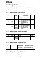
10.4.5 Assembly Instance Details
As mentioned previously, the External DeviceNet Interface is pre-configured to
consume 8 bytes of I/O data and produce 8 bytes of I/O data. As each DeviceNet
unit acts as the interface for 2 ASDs, the produced and consumed data is divided
equally between these drives. Currently, the External DeviceNet Interface directly
supports the Toshiba S7 drive series, and all command and status data provided in
sections 10.4.5.1 and 10.4.5.2 relate to this drive series only.
This data allocation may include more configurations and support for more drive lines
as future firmware versions are released. Be sure to periodically check the Internet
for new downloadable firmware versions and documentation to support your
DeviceNet unit and attached drives (refer to section 11).
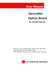
ASD Channel B
ASD Channel A
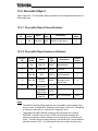
10.4.5.1 Output Instance 100 (ASD Command)
Byte #
Bit 7
Bit 6
Bit 5
Bit 4
Bit 3
Bit 2
Bit 1
Bit 0
0
DC Inject.
Braking
Acc / Dec
#1 / #2
Reserved
Reserved
Preset
Speed 4
Preset
Speed 3
Preset
Speed 2
Preset
Speed 1
1
DeviceNet DeviceNet
Cmd. Valid Freq. Valid
Fault
Reset
Emerg.
OFF
Free Run
Run / Stop
FWD /
REV
Jog
2
Drive A Frequency Command (Low Byte)
3
Drive A Frequency Command (High Byte)
4
DC Inject.
Braking
Acc / Dec
#1 / #2
5
DeviceNet DeviceNet
Cmd. Valid Freq. Valid
Reserved
Reserved
Preset
Speed 4
Preset
Speed 3
Preset
Speed 2
Preset
Speed 1
Fault
Reset
Emerg.
OFF
Free Run
Run / Stop
FWD /
REV
Jog
6
Drive B Frequency Command (Low Byte)
7
Drive B Frequency Command (High Byte)
Command Word
Bytes #0 / #1 and #4 / #5 represent the bit-mapped drive control command words.
These are the locations where run/stop, etc. commands are written. A more detailed
view of the command words with indicated values can be found in Table 2.
Using the example command word in Table 2, some representative command words
that can be used to control each of the attached drives via the DeviceNet network
are:
0xC400 ..........DeviceNet command valid, DeviceNet frequency valid, run forward
0xC600 ..........DeviceNet command valid, DeviceNet frequency valid, run reverse
0xC000 ..........DeviceNet command valid, DeviceNet frequency valid, drive stop
0xE000 ..........DeviceNet command valid, DeviceNet frequency valid, reset drive fault
0x0000...........Drive command and frequency source local (not from DeviceNet)
24
Note that whether or not the drive’s command and frequency command are selected
to be from the DeviceNet network, input (status) data is still available and will always
be returned to the DeviceNet scanner as I/O connection response data.
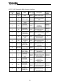
Table 2 : Toshiba S7 ASD Command Word Format
Bytes #0 / #4
Bytes #1 / #5
Bit
7
6
5
4
3
2
1
0
7
6
5
4
3
2
1
0
Function
0
Command source
Frequency command source
Fault reset
Emergency OFF command
Coast stop command
Run / stop command
Forward / reverse selection
Jog command
DC injection braking
Accel / decel #1/#2 selection
Reserved
Reserved
Preset speed 4
Preset speed 3
Preset speed 2
Preset speed 1
1
Local
Network
Local
Network
N/A
Reset
N/A
EOFF
N/A
Coast stop
Stop
Run
Forward
Reverse
N/A
Jog
N/A
DC injection cmd.
#1
#2
Value ignored
Value ignored
OFF
ON
OFF
ON
OFF
ON
OFF
ON
Frequency Command
The data contained in the frequency command word is the desired frequency
command multiplied by 100, and then converted to hexadecimal. In other words, if a
frequency command of 55.34Hz is desired, then 55.34 x 100 = 5534, which
converted to hexadecimal is 0x159E. The frequency command low byte (byte #2 or
#6) must therefore contain 0x9E and the frequency command high byte (byte #3 or
#7) must contain 0x15.
If the frequency command exceeds limiting drive parameters (such as UL or FH), the
drive will ignore it, maintaining its current setting.
25
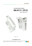
ASD Channel B
ASD Channel A
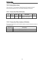
10.4.5.2 Input Instance 150 (ASD Status)
Byte #
Bit 7
Bit 6
Bit 5
Bit 4
Bit 3
Bit 2
Bit 1
Bit 0
0
DC Inject.
Braking
Status
Acc / Dec
#1 / #2
Status
Reserved
Reserved
Reserved
Reserved
Reserved
Reserved
1
Online /
Offline
Fault
Status
Reserved
Reserved
Reserved
Run / Stop
Status
FWD/REV
Status
Jog Status
2
Drive A Output Frequency (Low Byte)
3
Drive A Output Frequency (High Byte)
4
DC Inject.
Braking
Status
Acc / Dec
#1 / #2
Status
Reserved
Reserved
Reserved
Reserved
Reserved
Reserved
5
Online /
Offline
Fault
Status
Reserved
Reserved
Reserved
Run / Stop
Status
FWD/REV
Status
Jog Status
6
Drive B Output Frequency (Low Byte)
7
Drive B Output Frequency (High Byte)
Status Word
Bytes #0 / #1 and #4 / #5 represent the bit-mapped drive status words. These are
the locations where run/stop, etc. status values are monitored. A more detailed view
of the status words with indicated values can be found in Table 3.
Note that bits #14 and #15 of each status word is allocated to the DeviceNet
Interface. Bit #15 is used to indicate whether the DeviceNet Interface has
established an open line of communications with the drive connected to that channel.
Once a connection has been established with the drive, this bit will normally indicate
“Online”. While searching for a drive (such as during initialization) and when no drive
is connected, this bit will indicate “Offline”, and all other input data will be “0”. If this
status bit indicates “Offline”, but there is a drive connected to the channel in question,
check the cable connections and verify that the drive is powered.
As a user convenience, because the S7 ASD does not provide a “faulted” status bit in
its standard status word, bit #14 of each status word from the DeviceNet unit is used
to reflect the current faulted/not faulted status of the corresponding attached drive.
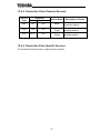
Output Frequency
Continuously reports the drive’s operating frequency. The value returned in this field
is the drive’s actual output frequency times 100. Therefore, in order to determine the
drive’s actual output frequency, divide this number by 100. For example, if the output
frequency high byte is 0x12 and the output frequency low byte is 0x34, then 0x1234
converted to decimal is 4660. Dividing this number by 100, the actual operating
frequency of 46.60Hz is obtained.
26
Table 3 : Toshiba S7 ASD Status Word Format
Bytes #0 / #4
Bytes #1 / #5
Bit
Function
7
6
5
4
3
2
1
0
7
Drive online / offline status
ASD fault status
Reserved
Reserved
Reserved
Run / stop status
Forward / reverse status
Jog status
6
5
4
3
2
1
0
Accel / decel #1/#2 status
Reserved
Reserved
Reserved
Reserved
Reserved
Reserved
0
1
Offline
Online
Not faulted
Faulted
Always “0”
Always “0”
Always “0”
Stopped
Running
Forward
Reverse
Not jogging
Jogging
Not DC injection
DC injection
braking
braking
#1
#2
Always “0”
Always “0”
Always “0”
Always “0”
Always “0”
Always “0”
DC injection braking status
27
10.5 Connection class
Class code 0x05. The Connection Class allocates and manages the internal
resources associated with both I/O and Explicit Messaging Connections.
10.5.1 Connection Class Attributes
Attribute
ID
Access
Rules
Name
1
Get
Revision
Data
Type
Description
UINT Revision of this object.
Default
Value
1
10.5.2 Connection Class Instance Attributes
The Instance IDs utilized by the DeviceNet Interface connection objects are shown in
the following table:
Connection
Instance ID #
1
2
Description
References the Explicit Messaging Connection
References the Polled I/O Connection
28
10.5.2.1 Master/Slave Explicit Messaging Connection Object Instance Attributes
Attribute
ID
Access
Rules
Name
Data Type
Description
Default
Value
1
Get
state
USINT
State of the object
--
2
Get
instance_type
USINT
Indicates connection
type
0
3
Get
transportClass
_trigger
USINT
Connection behavior
0x83
4
Get
produced_
connection_id
UINT
5
Get
consumed_
connection_id
UINT
0x0403 +
(MAC ID
<< 3)
0x0404 +
(MAC ID
<< 3)
6
Get
initial_comm
_characteristics
USINT
7
Get
8
Get
9
Get / Set
expected_
packet_rate
UINT
Placed in CAN ID
field when
transmitting
CAN ID field value
denoting received
messages
Defines producing /
consuming message
groups
Max number of bytes
transmitted across
this connection
Max number of bytes
received across this
connection
Defines timing
associated with this
connection
12
Get / Set
watchdog_
timeout_action
USINT
13
Get
produced_
connection_
path_length
UINT
14
Get
produced_
connection_
path
Array of
USINT
15
Get
consumed_
connection_
path_length
UINT
16
Get
consumed_
connection_
path
Array of
USINT
17
Get
production_
inhibit_time
UINT
produced
_connection
_size
consumed
_connection
_size
UINT
UINT
29
Inactivity/watchdog
timeout action
Number of bytes in
produced_connection
_path attribute
Specifies Application
Object(s) whose data
is to be produced by
this connection
Number of bytes in
consumed_
connection_path
attribute
Specifies Application
Object(s) whose data
is to be consumed by
this connection
Defines minimum
time between new
data production
0x21
40
40
2500
1
0
Empty
0
Empty
0
10.5.2.2 Poll Connection Object Instance Attributes
Attribute
ID
Access
Rules
Name
Data Type
Description
Default
Value
1
Get
state
USINT
State of the object
--
2
Get
instance_type
USINT
Indicates connection
type
1
3
Get
transportClass
_trigger
USINT
Connection behavior
0x82
4
Get
produced_
connection_id
UINT
5
Get
consumed_
connection_id
UINT
6
Get
initial_comm
_characteristics
USINT
7
Get
8
Get
9
Get / Set
expected_
packet_rate
UINT
12
Get / Set
watchdog_
timeout_action
USINT
13
Get
produced_
connection_
path_length
UINT
14
Get
produced_
connection_
path
Array of
USINT
15
Get
consumed_
connection_
path_length
UINT
16
Get
consumed_
connection_
path
Array of
USINT
17
Get
production_
inhibit_time
UINT
produced
_connection
_size
consumed
_connection
_size
UINT
UINT
30
Placed in CAN ID
field when
transmitting
CAN ID field value
denoting received
messages
Defines producing /
consuming message
groups
Max number of bytes
transmitted across
this connection
Max number of bytes
received across this
connection
Defines timing
associated with this
connection
Inactivity/watchdog
timeout action
Number of bytes in
produced_connection
_path attribute
Specifies Application
Object(s) whose data
is to be produced by
this connection
Number of bytes in
consumed_
connection_path
attribute
Specifies Application
Object(s) whose data
is to be consumed by
this connection
Defines minimum
time between new
data production
0x03C0 +
MAC ID
0x0405 +
(MAC ID
<< 3)
0x01
8
8
0
0
6
20 04 24
96 30 03
6
20 04 24
64 30 03
0
10.5.3 Connection Class Common Services
Service
Code
Supported
Class
Instance
Service Name
Description of Service
0x05
No
Yes
Reset
Used to reset all resettable
connection objects.
0x0E
Yes
Yes
Get_Attribute
_Single
Returns the contents of the
specified attribute.
0x10
N/A
Yes
Set_Attribute
_Single
Modifies the value of the
specified attribute.
10.5.4 Connection Class Specific Services
The Connection Class provides no object specific services.
31
10.6 Parameter Class
Class code 0x0F. The parameter class provides access to the various configuration
parameters for each connected drive as well as for the External DeviceNet Interface
itself. The supported parameters for each drive and their allowable adjustment
ranges are defined in the appropriate Electronic Data Sheet (EDS). EDS sheets for
all available DeviceNet interface firmware versions and supported drive series and
configurations can be downloaded via the internet from http://www.iccdesigns.com.
Accessing parameter object instances associated with connected drive parameters
accesses those drive parameters directly (i.e. a GET service will read a parameter
value from the drive, and a SET service will write a parameter value to the drive).
One parameter group is reserved for configuration of parameters resident on the
DeviceNet interface itself. The supported parameters comprising this group are
detailed in Table 4.
Table 4: DeviceNet Interface Configuration Group Parameters
Parameter Name
Access
Rules
Data
Type
Drive A Network
Communication
Loss Action
Get /
Set
USINT
Drive A Preset
Speed
Get /
Set
USINT
Drive B Network
Communication
Loss Action
Get /
Set
USINT
Drive B Preset
Speed
Get /
Set
USINT
DNETOBJ BOI
attribute
Interface firmware
Application
version
Get /
Set
BOOL
Get
STRUCT
of:
USINT
USINT
Interface firmware
Bootstrap Loader
version
Get
Adjustment Range
0 = Set all consumed data to 0 (default)
1 = Do nothing (retain last data values)
2 = Stop motor with decelerated stop
3 = Stop motor with coast stop
4 = Trip drive “E” (emergency off)
5 = Run a preset speed
1 ∼ 15 = preset speeds #1 ∼ #15
(default = 1, applies only when above
parameter is set to “Run a preset speed”)
Sets DeviceNet object’s bus-off interrupt
attribute selection (default = 0)
Version
Revison
STRUCT
of:
USINT
USINT
Version
Revision
32
11. MMI Port Use
The External DeviceNet Interface is equipped with an on-board RS232 Man-Machine
Interface (MMI) port. This port allows the unit to communicate to a standard personal
computer via its serial (COM) port. This can be accomplished by using the 2-meter
DB9-to-RJ45 MMI port cable provided with your interface kit.
Current support for the MMI port is provided by the free ICC FlashLoader utility,
which runs on the Microsoft Windows NT/95/98/2000 operating systems. This utility
allows the DeviceNet interface’s internal flash memory to be upgraded in the field,
providing alternative control data, new parameter access, and future drive series
support.
We are continually striving to enhance the functionality and flexibility of our products,
and therefore periodically release new embedded firmware to achieve these goals
and meet customer requests. The FlashLoader utility, usage instructions, new flash
firmware files and all related documentation (such as updated user manuals and
Electronic Data Sheet (EDS) files) can be downloaded as complete support
packages from http://www.iccdesigns.com. Check this internet site periodically to
determine if new support packages have been released for your DeviceNet interface
unit.
33
12. Notes
34
35
36
TOSHIBA INTERNATIONAL CORPORATION
INDUSTRIAL DIVISION
13131 West Little York Rd., Houston, TX 77041
Tel: [800] 231-1412 / [713] 466-0277 Fax: [713] 466-8773
World Wide Web http://www.tic.toshiba.com
Printed in U.S.A