1
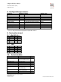
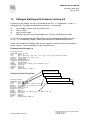
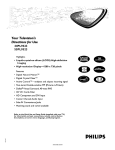
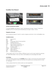
User Manual
CANgine
FMS
Edition 10 / November 2007
FW version 6.4 and above
CANgine FMS User Manual
November 2007 (E10)
page 2 of 28
The information given in this document was compiled and checked carefully. Nevertheless
ESS assumes no liability for any mistakes. ESS also assumes no liability for any damage
resulting from use of this manual or products described herein.
ESS reserves the right to make changes on information given in this document and on features of products described herein without prior notification.
Publication and reproduction of this document or parts of it are only allowed with written
agreement of ESS.
ESS Embedded Systems Solutions GmbH
Industriestrasse 15
D-76829 Landau
CANgineFMSManualEng_E10
CANgine FMS User Manual
November 2007 (E10)
page 3 of 28
Version History
Edition
10
Date
Nov 2007
9
8
7
6
Nov 2006
Sep 2007
Jun 2006
Apr 2006
5
4
3
Dec 2005
May 2005
Jan 2005
2
1
June 2004
Sep 2003
State
Sprinter Flag for Daimler Sprinter is introduced.
If the flag is set with the SP1 command, the cycle time for FMS
message EngineSpeed is modified to 1000 ms instead of 20 ms
as defined in FMS standard. Daimler promised to fix the bug in
spring 2008. (Firmware Version 6.5)
I command to set identifier string added (Firmware Version 6.3)
Data Request Mode implemented (Firmware Version 6.1)
Bus FMS implemented (Firmware Version 6.0)
CycleTimeUnit implemented;
change behaviour of green RUN LED
Corrections, clarifications and adaptation to firmware 5.0
Hint to SAE J1939
Correction M command
New Parameter Autostart and Echo (FW version 4.5 and later)
corrections / additions
first edition
© Copyright 2003 - 2007
ESS Embedded Systems Solutions GmbH
Industriestr. 15
D-76829 Landau
(49) 6341 3487-0
(49) 6341 3487-29
[email protected]
www.ESSolutions.de
www.CANgine.com
CANgineFMSManualEng_E10
ESS Embedded Systems Solutions GmbH
Industriestrasse 15
D-76829 Landau
CANgine FMS User Manual
November 2007 (E10)
page 4 of 28
Related Documents
SAE J1939 / 71
Vehicle Application Layer
Clarification of FMS data
Notation of special characters
[CR] Enter key or character code carriage return (0x0D)
[LF] character code linefeed (0x0A)
[BELL] character code bell (0x07)
ESS Embedded Systems Solutions GmbH
Industriestrasse 15
D-76829 Landau
CANgineFMSManualEng_E10
CANgine FMS User Manual
November 2007 (E10)
page 5 of 28
Contents
1.
2.
3.
4.
5.
Introduction .................................................................................................................... 7
FMS Protcol Types......................................................................................................... 7
Installation...................................................................................................................... 8
Initializing procedure ...................................................................................................... 9
Configuration mode .......................................................................................................10
5.1
Command overview................................................................................................10
5.2
? command – show parameters .............................................................................11
5.3
A Command - axleCount ........................................................................................11
5.4
AS Command – autostart .......................................................................................11
5.5
C Command – cycleTime .......................................................................................12
5.6
CU Command – cycleTimeUnit ..............................................................................12
5.7
D Command – decimal separator ...........................................................................12
5.8
E Command – echo on or off..................................................................................12
5.9
F Command – error information .............................................................................13
5.10
I Command – Identifier String .............................................................................13
5.11
M Command – mask for output values................................................................13
5.12
P Command – select protocol .............................................................................14
5.13
R Command - restart ..........................................................................................14
5.14
S Command – screen format ..............................................................................15
5.15
SP Command – Set / Reset Sprinter Flag...........................................................15
5.16
U Command – uart baudrate ..............................................................................15
5.17
V Command – version information......................................................................16
6. Operating mode ............................................................................................................17
6.1
Cyclic operation......................................................................................................17
6.2
Data Request Operation.........................................................................................17
6.3
Watchdog for FMS messages ................................................................................17
6.4
Value ranges..........................................................................................................17
6.5
FMS messages, mask bits and FMS cycle times....................................................18
6.6
Output Formats ......................................................................................................18
6.6.1
Screen format (S = 1)......................................................................................18
6.6.1.1
Truck FMS Protocol .................................................................................19
6.6.1.2
Bus FMS Protocol ....................................................................................19
6.6.2
Spreadsheet Format (S = 0)............................................................................19
6.6.2.1
Truck FMS Protocol .................................................................................19
6.6.2.2
Bus Protocol.............................................................................................20
6.7
Output Values ........................................................................................................20
6.7.1
Identifier string – optional output field ..............................................................20
6.7.2
Time – internal time information ......................................................................20
6.7.3
EngSpeed – engine speed ..............................................................................20
6.7.4
Acc – accelerator pedal position......................................................................20
6.7.5
TCO – tachograph information ........................................................................20
6.7.6
Speed – wheel based speed ...........................................................................21
6.7.7
Service – service distance...............................................................................21
6.7.8
Distance - vehicle distance..............................................................................21
6.7.9
EngHours - engine time...................................................................................21
6.7.10 FuelC - fuel consumption ................................................................................22
6.7.11 Weight.............................................................................................................22
6.7.12 EngTemp - cooloing temperature ....................................................................22
6.7.13 FuelL - fuel level..............................................................................................22
6.7.14 VehID - vehicle ID ...........................................................................................22
6.7.15 FMS – FMS version ........................................................................................22
CANgineFMSManualEng_E10
ESS Embedded Systems Solutions GmbH
Industriestrasse 15
D-76829 Landau
CANgine FMS User Manual
November 2007 (E10)
page 6 of 28
6.7.16 Gear – transmission information......................................................................22
6.7.17 DoorControl1...................................................................................................22
6.7.18 DoorControl2...................................................................................................22
6.7.19 AirSuspension .................................................................................................23
6.7.20 AirSupply.........................................................................................................23
6.7.21 Alternator ........................................................................................................23
6.7.22 TimeDate ........................................................................................................23
6.8
Error handling.........................................................................................................23
6.8.1
Cycle time overflow .........................................................................................24
6.8.2
CAN bus errors ...............................................................................................24
7. Implementation Hints.....................................................................................................25
7.1
Configuration..........................................................................................................25
7.2
Autostart.................................................................................................................25
7.3
Echo.......................................................................................................................25
8. Configuration parameter................................................................................................26
9. Connector pinout ...........................................................................................................26
9.1
Serial link ...............................................................................................................26
9.2
CAN .......................................................................................................................26
10.
Technical data ...........................................................................................................26
11.
Changes starting with firmware version 5.0................................................................27
ESS Embedded Systems Solutions GmbH
Industriestrasse 15
D-76829 Landau
CANgineFMSManualEng_E10
CANgine FMS User Manual
November 2007 (E10)
page 7 of 28
1. Introduction
Thank you for choosing a product of our CANgine product family. The CANgine family is
based on high performance 8 bit microcontrollers with integrated full CAN interface and flash
memory. With these controllers we are able to build extremely small but powerful CAN units.
CANgine FMS is powered via the CAN connector. The
serial link 'speaks' pure ASCII code. Therefore CANgine
FMS can be used on nearly any device with a serial link
to which you have access. So the connection to CAN bus
is possible for nearly all automation devices even for
older ones.
In its standard case, CANgine FMS only measures 53 x
34 x 16 mm³ (2.08 x 1.34 x 0.63 inch³). If this does not fit for some applications CANgine
FMS can be delivered in other cases or without case in customer specific variants. Due to
the modular concept of CANgine in hardware and firmware this is possible even at lower
production volumes. Email or call our sales department if you have special requirements.
The serial link of CANgine FMS supports baud rates from 2.400 up to 115.200 bps. The CAN
baud rate is fixed to 250 kbps as defined by the FMS standard. Setting into operation and
troubleshooting is made easy due to the two LEDs.
Updating CANgine’s software or loading custom specific implementations is easy and can be
done without opening CANgine’s case.
2. FMS Protcol Types
Startign with firmware 6.0 CANgine FMS supports both FMS protocol variants: Truck FMS
(the older one) and Bus FMS (the newer one). Bus FMS differs in a few CAN bus messages
and defines some new CAN messages related to busses. The table shows the differences
between the two protocol types. Details are outlines in chapter 5.10 where the M command
to mask the output variables is described.
Nachricht
CCVS
VehicleWeight
ServiceDistance
AMB
DC1
DC2
TD
AIR1
AS
ETC2
ASC4
Truck-FMS
ParkingBrake not defined
CAN message defined
CAN message defined
CAN message not defined
CAN message not defined
CAN message not defined
CAN message not defined
CAN message not defined
CAN message not defined
CAN message not defined
CAN message not defined
CANgineFMSManualEng_E10
Bus-FMS
PTOState not defined
CAN message not defined
CAN message not defined
CAN message defined
CAN message defined
CAN message defined
CAN message defined
CAN message defined
CAN message defined
CAN message defined
CAN message defined
ESS Embedded Systems Solutions GmbH
Industriestrasse 15
D-76829 Landau
CANgine FMS User Manual
November 2007 (E10)
page 8 of 28
3. Installation
The picture shows how to connect
CANgine FMS to a CAN / FMS
Gateway. Power supply is connected via pin 9 and pin 3 of the
CAN connector as proposed by
CiA1. The maximum supply voltage
is 30 V. Applying higher voltages
will lead to damages. If you are not
sure of the need for a terminating
resistor of 120 Ohm in your installation ask your truck service partner.
After applying the supply voltage
the green LED blinks. The blinking
code shows the baud rate of the
serial link:
Pulses
2
3
4
5
6
7
8
Baudrate
115200
57600
38400
19200
9600
4800
2400
With the factory default settings (AS = 0) CANgine FMS is now waiting for either the key 's’ or
the enter key [CR]. If 's' is received the CAN bus is initialized and the output of FMS data to
the serial link is started. If [CR] is received CANgine FMS switches to configuration mode.
The serial link of CANgine's host should have the following setting:
•
•
•
•
•
1
baud rate as indicated by CANgine FMS (see table above)
8 data bits
no parity
1 stop bit
no handshake
CANinAutomation (www.can-cia.org)
ESS Embedded Systems Solutions GmbH
Industriestrasse 15
D-76829 Landau
CANgineFMSManualEng_E10
CANgine FMS User Manual
November 2007 (E10)
page 9 of 28
4. Initializing procedure
On power on some internal checks are run to guarantee a good operation of CANgine FMS.
One of these is checking the EEPROM parameter contents with a checksum. To visualize
these checks the red LED is switched on immediately after applying power. If all checks are
run successfully the red LED is switched off. If a checksum failure in internal EEPROM is
detected, the red LED blinks with a code of four.
Pulses Failure
4
Checksum failure or memory failure parameter data
If a failure in the parameter data area is detected the default parameters are loaded. The
failure is signalized by the blinking error LED until error information is read with the F command.
If the internal checks are completed successfully the peripheral devices (RS232 and CAN)
are initialized and the red LED is switched off. The green LED blinks with a blinking code
signaling the serial baud rate (see table above). Now CANgine FMS is waiting for either the
'S' or the enter key. No other input is accepted at this point. Key 'S' (without following [CR])
starts CANgine FMS data output, key enter (single CR) feeds to the configuration mode.
•
•
Either key stops blinking the green LED, which from now on signals the operating state:
'Flashig' (900 ms off, 100 ms on) means CAN is opened, FMS messages are decoded
and messages are send to the serial link,
'Blinking' (500 ms off, 500 ms on) means CANgine FMS is in configuration mode.
If parameter autostart is set (AS = 1) CANgine FMS starts immediately after power on checks
with data output to the serial link with the last parameterized baud rate if cycleTime unequal
zero. If cycleTime equals zero CANgine FMS waits for the first data request character. All
parameters are taken from EEPROM.
CANgineFMSManualEng_E10
ESS Embedded Systems Solutions GmbH
Industriestrasse 15
D-76829 Landau
CANgine FMS User Manual
November 2007 (E10)
page 10 of 28
5. Configuration mode
The configuration mode can be entered in two ways:
•
•
From normal operating mode by pressing the key ^s (Ctrl + s) (character code 0x13)
(without following [CR])
After power on with autosart disabled by a single [CR].
When entering the configuration mode CANgine FMS sends the message "[LF]CANgine
FMS in configuration mode[CR][LF]" via the serial link and waits for inputs.
In configuration mode the CAN channel is closed and CANgine doesn't generate ACK bits on
the CAN bus. The green RUN LED is blinking (500 ms off, 500 ms on).
All parameters entered in configuration mode are immediately stored in non volatile memory
and stay active even if power is disconnected. Due to writing the EEPROM configuration
commands must not be entered at every start of CANgine FMS.
CANgine FMS works case-insensitive which means 'A' can be replaced by 'a'.
If echo is disabled (E = 0) all commands received via serial link are acknowledged by
[CR][LF] or by the string "Illegal command or parameter[CR][LF]". If echo is enabled (E = 1)
the whole command string is echoed finished with [CR][LF]. In case of syntax error the command string isn't echoed.
Commands leading to a write to the EEPROM (A, AS, C, CU, D, E, M, S, U) are acknowledged after writing the EEPROM. These commands can cause the message "[BELL]Error
writing EEPROM[CR][LF]" if writing the internal EEPROM fails.
Never send a new command to CANgine FMS if you haven't received an positive or negative
acknowledge for the last command either by [CR][LF], the command echo or the error message.
5.1
Command overview
?[CR]
An[CR]
Asn[CR]
Cn[CR]
Cuc[CR]
Dc[CR]
En[CR]
F[CR]
Istring[CR]
Mcccc[CR]
Pc[CR]
R[CR]
Sn[CR]
SPn[CR]
Un[CR]
V[CR]
Shows configuration parameters
Sets axle count (Parameter AxleCount)
Autostart on (n=0) or off (n=1)
Sets cycle time for output to serial link (Parameter CycleTime)
Sets cycle time unit to either 'M' (milliseconds) or 'S' (seconds)
Sets decimal separator for output to serial link (Parameter DecChar)
Echo off (n=0) or on (n=1)
Outputs error information
Sets the string to be sent in front of CANgine's serial output
Sets mask to define the output values (Parameter OutMask)
Sets protocol to Truck FMS (c=T) or Bus FMS (c=B)
Restart from configuration mode
Sets output to screen or table format (Parameter ScreenForm)
Sets or resets 'Sprinter watchdog time' for EngineSpeed message
Sets RS232 baud rate (Parameter UartBaud)
Outputs version information
ESS Embedded Systems Solutions GmbH
Industriestrasse 15
D-76829 Landau
CANgineFMSManualEng_E10
CANgine FMS User Manual
November 2007 (E10)
page 11 of 28
5.2
? command – show parameters
Displays the actual parameter setting
Format:
?[CR]
Answer:
Parameter set
Error message on wrong command format
Output format (default factory settings):
A
AS
C
CU
D
E
I
M
P
S
SP
5.3
(AxleCount)
(Autostart)
(CycleTime)
(CycleTimeUnit)
(DecimalSeperator)
(Echo)
(ID string)
(MaskForOutput)
(Protocol)
(ScreenFormat)
(Sprinter Bug Fix)
3
Off
1000
M (msec)
,
Off
not defined
1FFF
T
1
0
A Command - axleCount
Sets the count of axles used for the output format of FMS message Weight in truck protocol.
Standard value is 3. If CANgine is in Bus protocol mode, this parameter is meaningless.
Format:
An[CR]
n = {1..16}
Answer:
[CR][LF], if value is accepted
Error message on wrong parameter value or command format
5.4
AS Command – autostart
In the default factory setting (AS = 0) CANgine FMS expects a [CR] or the character 'S' after
applying power. Receiving [CR] CANgine FMS switches to configuration mode, receiving the
character 'S' CANgine FMS switches to normal operating mode. If the parameter autostart is
set by AS = 1, CANgine FMS enters normal operating mode immediately after applying
power: The message "[LF]CANgine FMS in normal operation mode[CR][LF]" is send to serial
link, followed by the first data output (see chapter 6.6.1).
Format:
ASn[CR]
n = {0 | 1}
Answer:
[CR][LF] if parameter is accepted
Error message on wrong parameter value or command format
CANgineFMSManualEng_E10
ESS Embedded Systems Solutions GmbH
Industriestrasse 15
D-76829 Landau
CANgine FMS User Manual
November 2007 (E10)
page 12 of 28
5.5
C Command – cycleTime
The C command sets the cycle time of the output to the serial link. Accepted values are zero
or between 100 and 60,000. The cycle time is internally calculated from the value given with
C command and the unit given with CU command. If the cycle time is to short for output of all
values (selected with M command) with the given UART baud rate, error bit 0 is set with the
next serial output and the red LED signals cycle overrun (see chapter 6.8.1 for details).
Format:
Cn[CR]
N = {0 | 100..60000}
Answer:
[CR][LF] if parameter is accepted
Error message on wrong parameter value or command format
'Cycle time too short, set to 100 ms!' if the time is unequal 0 and less than 100 ms.
5.6
CU Command – cycleTimeUnit
The CU command sets the cycle time unit of the output to the serial link either to milliseconds
('M') or seconds ('S'). If the resutling cycle time is less than 100 ms the minimum value of 100
ms is set automatically. In this case an output message is generated.
Format:
CUc[CR]
c = {'M' | 'm' | 'S' | 's'}
Answer:
[CR][LF] if parameter is accepted
Error message on wrong parameter value or command format
'Cycle time too short, set to 100 ms!' if the time is less than 100 ms.
5.7
D Command – decimal separator
Define the separator character for numeric values used in the output strings. This is helpful if
table output is used and data is needed for table calculations. You can either choose ','
(comma) or '.' (dot).
Format:
Dc[CR], with c = . or c = ,
Answer:
[CR][LF] if parameter is accepted
Error message on wrong parameter value or command format
5.8
E Command – echo on or off
CANgine FMS supports the possibility to get the received command string echoed. The echo
is send after the command is executed successfully which means after writing the EEPROM.
One exception is the answer to the U command (changing serial baud rate), which is echoed
before the baud rate is switched and the new parameter is stored. The host control is responsible to wait about 200 ms after an acknowledged U command before sending a new
command with the changed baud rate.
Format:
En[CR], with n = {0 | 1}
ESS Embedded Systems Solutions GmbH
Industriestrasse 15
D-76829 Landau
CANgineFMSManualEng_E10
CANgine FMS User Manual
November 2007 (E10)
page 13 of 28
Answer:
[CR][LF] if parameter is accepted and echo is switched from on (1) to off (0)
E1[CR][LF] if parameter is accepted and echo is switched from off (0) to on (1)
Error message on wrong parameter value or wrong command format
5.9
F Command – error information
Read and reset the internal error register.
Format:
F[CR]
Answer:
Fxx[CR][LF]
Error message on wrong command format
xx is a two digit hexadecimal code with the following bit meanings
7
res
6
checksum
failure
EEPROM
5
res
4
res
3
CAN Bus Off
2
CAN error
passive
1
res
0
Output cycle
time too short
An internal error is also signaled by the red LED with blinking codes (see 5.4). The red LED
is switched off and the error information reset to zero when error information is read and the
error reason is gone.
If the error is CAN Bus Off, the CAN controller is re-initialized on reading the error information.
5.10 I Command – Identifier String
With the I command a string can be defined which is always sent in front of the serial output.
The string is stored in non-volatile memory. To delete the string I[CR] must be entered. If the
string is deleted, the field in front of the time stamp is omitted. This is due to compatibility
reasons to older firmware versions. The string can contain any special characters excluding
';' which is used as field seperator in S0 output format. Be aware of confusing serial output if
you enter control characters inside the identifier string. If in doubt delete the string using
"I[CR]" and enter it again.
Format:
Istring[CR]
string is an alphanumeric string with zero or up to twenty characters
Answer:
[CR][LF] if string is stored
Error message on wrong command format, illegal string length or illegal characters in
string
5.11 M Command – mask for output values
The M command sets the mask for the FMS messages involved in output values. Acceptable
parameter range is between 1 and 1FFEEF. Value has to be input in hexadecimal notation:
Format:
Mcccccc[CR] with cccccc = mask register (max. 6 hexadecimal digits)
CANgineFMSManualEng_E10
ESS Embedded Systems Solutions GmbH
Industriestrasse 15
D-76829 Landau
CANgine FMS User Manual
November 2007 (E10)
page 14 of 28
Answer:
[CR][LF] if value is accepted
Error message on wrong parameter value or command format
In the mask register the bits related to the desired output messages has to be set to '1'. If a
value should not appear in the output the related bit has to be set to '0'. The table shows the
bit positions and the related messages for the both protocols Truck and Bus.
Bit
Truck
Bus
Bit
Truck
Bus
7
Fuel
Consumption
Fuel
Consumption
15
reserved1)
Door
Control2
6
5
Engine
Hours
Engine
Hours
14
not
defined1)
Door
Control1
Service
Distance
not
defined1)
3
2
CCVS
TCO
CCVS
TCO
13
not
defined1)
Transmission
Control
12
FMS
Version
FMS
Version
11
Vehicle
ID
Vehicle
ID
Bit
Truck
20
not
defined1)
Ambient
Temp
19
not
defined1)
Time
Date
Bus
1)
4
Vehicle
Distance
Vehicle
Distance
1
Accelerator
Pedal
Accelerator
Pedal
10
0
Engine
Speed
Engine
Speed
9
8
Fuel
Level
Fuel
Level
Engine
Temp.
Engine
Temp.
Vehicle
Weight
not
defined1)
18
not
defined1)
Alternator
Speed
17
not
defined1)
Air
Supply
16
not
defined1)
Air
Suspension
'reserved' and 'not defined' bits has to be set to '0'
When CANgine is in Truck protcol mode (P=T) with M1FFF all messages are enabled for
output. When CANgine is in Bus protocol mode (P=B) with M1FFEEF all messahes are enabled for output.
5.12 P Command – select protocol
The P command selcts either the Truck or the Bus protocol. The protocol selected affects the
output of the CCVS message values (see chapter x). When the protocol is switched with the
P command, the mask register is set to a default value related to the protocol:
•
•
1FFF if Truck protocol is selected,
1FFEEF if Bus protocol is selected.
Format:
Pc[CR]
C 0 {b | B | t |T}
Answer:
[CR][LF] if command is accepted
Error message on wrong parameter value or command format
5.13 R Command - restart
Ends the configuration mode and restarts CAN bus and output to serial link. After a successful start the green RUN LED starts to flash (900 ms off, 100 ms on).
Format:
R[CR]
ESS Embedded Systems Solutions GmbH
Industriestrasse 15
D-76829 Landau
CANgineFMSManualEng_E10
CANgine FMS User Manual
November 2007 (E10)
page 15 of 28
Answer:
Message "[LF]CANgine FMS in normal operation mode[CR][LF]" immediately followed by the first data output (see chapter 6.6.1 or Fehler! Verweisquelle konnte
nicht gefunden werden.).
Error message on wrong command format
5.14 S Command – screen format
The S command sets the format of the serial output.
S0 sets the spreadsheet format for output. All values are separated by the ';' character and
are output in one line beginning with the time stamp. For details see chapter x.
S1 sets readable format where each FMS message is output on an own line and each value
is preceded by its name and followed by its unit if applicable. For details see chapter x.
Format:
Sn[CR]
n = {0|1}
Answer:
[CR][LF] if command is accepted
Error message on wrong parameter value or command format
5.15 SP Command – Set / Reset Sprinter Flag
In the default factory setting (SP = 0) CANgine FMS assumes the cycle time of the EngineSpeed message to be 20 ms as described in the FMS standard. Daimler's Sprinters build
in 2007 and early 2008 supporting FMS delivers the EngineSpeed message with a cycle time
of 1000 ms. As CANgine FMS surveys the cycle times to detect malfunction of CAN FMS
busses it leads to malfunction if a CANgine FMS is connected to a Daimler Sprinter build in
2007 and early 2008.
Setting the Sprinter flag helps in such cases to avoid '*' characters in the serial data stream
instead of the actual engine speed value. But you have to be aware that the engine speed
value is 1 second old if you receive it.
SP0 resets the value to 20 ms.
Format:
SPn[CR]
n = {0 | 1}
Answer:
[CR][LF] if parameter is accepted
Error message on wrong parameter value or command format
5.16 U Command – uart baudrate
The U command sets the baud rate of the serial link. The answer is given with the old baud
rate and if command is accepted the baud rate is switched immediately after the answer output.
Command
U1
U2
U3
bps
115200
57600
38400
CANgineFMSManualEng_E10
ESS Embedded Systems Solutions GmbH
Industriestrasse 15
D-76829 Landau
CANgine FMS User Manual
November 2007 (E10)
page 16 of 28
U4
U5
U6
U7
19200
9600
4800
2400
Format:
Un[CR]
Answer:
[CR][LF] command successfull
Error message on wrong parameter value or command format
5.17 V Command – version information
The V command results in version information for hardware and software
Format:
V[CR]
Answer:
Vhhss[CR][LF]
with hh = hardware version and ss = software version
Error message on wrong command format
ESS Embedded Systems Solutions GmbH
Industriestrasse 15
D-76829 Landau
CANgineFMSManualEng_E10
CANgine FMS User Manual
November 2007 (E10)
page 17 of 28
6. Operating mode
In normal operating mode the CAN channel is active, the received FMS messages are interpreted and the received values are stored in an internal process image. ASCII output for the
serial link is built up and send either in a cycle given by the parameter CycleTime and CycleTimeUnit or if the data request character is received (if cycleTime equals zero). Output is
given in the format defined by the parameter ScreenFormat. Only messages marked with a 1
Bit in the parameter MaskForOutput are included.
6.1
Cyclic operation
Cyclic operation is achieved by setting cycle time unequal from zero with the 'C' command
(see chapters 5.5 and 5.6). In the cyclic operation mode the data output is started when
CANgine enters normal operating mode. When starting output a timer is also started with the
parameterized cycle time. When this timer is expired the next output is started. If the time for
data output is longer than the parameterized cycle time the error 'Output cycle Time Too
Short' is signaled.
6.2
Data Request Operation
Data request operating mode is achieved by setting the cycle time to zero. In this case no
data output is generated until the 'data request character' (P) is received. When this character is received, the data output is build up from the process image and send to the serial link.
The data request character can be sent immediately after entering normal operation mode.
After sending the data request character a latency time is needed in which error conditions
are checked and the data output is build up.
As in cyclic operation the data request character must not be sent in shorter cycles than the
serial data output needs due to the parameterized output variables and baud rate. If this
happens the 'data output cycle too short' error is signaled.
6.3
Watchdog for FMS messages
If any parameter is missed because no FMS message was yet available the character '*' is
output instead of the value. All FMS messages are monitored by a watchdog timer which is
set to 1.5 times the cycle time defined in the FMS standard (see table in chapter 6.5). If a
FMS message is missed too long '*' characters are output instead of the last received values.
The watchdog timer for the axle weight messages is a little bit more sophisticated. As the
cycle time depends on the number of axles, the time is set according to the parameter AxleCount (command A). If the parameterized number of axles is less than the real number of
axles on the vehicle the calculated watchdog time is too short. This setting results in the occasional output of '*'.
For the special case CANgine FMS is working in a Daimler Sprinter build in 2007 and early
2008 there is a special parameter to modify the watchdog for the EngineSpeed message
from 20 ms to 1000 ms. With the SP1 command the watchdog time is set to 1000 ms. The
factory default setting is SP0 with cycle time set to 20 ms.
6.4
Value ranges
SAE J1939-71 defines for every variable an allowed range and ranges with the meanings
•
out of range
CANgineFMSManualEng_E10
ESS Embedded Systems Solutions GmbH
Industriestrasse 15
D-76829 Landau
CANgine FMS User Manual
November 2007 (E10)
page 18 of 28
•
•
error indicator
not available (at actual time or in the truck)
If such a value is received on the FMS bus the following characters are output instead of
numerical values:
•
•
•
'o' for out of range
'e' for error
'n' for not available
6.5
FMS messages, mask bits and FMS cycle times
Message
Engine speed
Accelerator Pedal
TCO
CCVS
Service Distance
Vehicle Distance
Engine Hours
Fuel Consumption
Vehicle Weight
Engine Temperature
Fuel Level
Vehicle ID
FMS Version
TransmissionControl
DoorControl1
DoorControl2
AirSuspension
AirSupply
AlternatorSpeed
TimeDate
AmbTemp
Cycle Time
[ms]
1
20
50
50
100
1.000
1.000
1.000
1.000
1.000
1.000
1.000
10.000
10.000
100
100
100
100
1.000
1.000
1.000
1.000
Mask Bit
0
1
2
3
4
5
6
7
8
9
10
11
12
13
14
15
16
17
18
19
20
Mask Value Truck
[hex]
FMS
0x00'0001
yes
0x00'0002
yes
0x00'0004
yes
0x00'0008
yes
0x00'0010
yes
0x00'0020
yes
0x00'0040
yes
0x00'0080
yes
0x00'0100
yes
0x00'0200
yes
0x00'0400
yes
0x00'0800
yes
0x00'1000
yes
0x00'2000
no
0x00'4000
no
0x00'8000
no
0x01'0000
no
0x02'0000
no
0x04'0000
no
0x08'0000
no
0x10'0000
no
Bus
FMS
yes
yes
yes
yes
no
yes
yes
yes
no
yes
yes
yes
yes
yes
yes
yes
yes
yes
yes
yes
yes
Default factory setting for the mask bits is 1FFF when Truck protocol is selected and 1FFEEF
when Bus protcol is selected which means that all messages are included in output.
6.6
Output Formats
Output can be formatted in two ways. The following chapters explain the formats and the
variables.
6.6.1 Screen format (S = 1)
With parameter s set to 1 a readable 'screen format' with variable names and physical units
is selected. See below the outputs for the default masks in Truck protocol mode and in Bus
protocol mode.
1
see chapter 5.15 for special treatement
ESS Embedded Systems Solutions GmbH
Industriestrasse 15
D-76829 Landau
CANgineFMSManualEng_E10
CANgine FMS User Manual
November 2007 (E10)
page 19 of 28
6.6.1.1
Truck FMS Protocol
IdentifierString
0-00:11:56.961
EngSpeed 2725,125 rpm
Accel
51,2 %
TCO
78,12 km/h MD:1 OS:0 DI:0 TP:0 HI:0 EV:0
Speed
78,12 km/h CC:1 BR:0 CS:0 PTO:1
Service +3205 km
Distance 45342,125 km
EngHours 975,05 h
FuelC
9839,0 L
Weight
1000,0 kg (n) 2000,0 kg (n) 3000,0 kg (n)
EngTemp +71 degr
FuelLev 60,4 %
VehID
CANgine
FMS
01.00 Diag:0 Requ:0
6.6.1.2
D1:1/3/1 D2:0/2/7
Bus FMS Protocol
IdentifierString
0-00:22:15.273
EngSpeed 2725,125 rpm
Accel
51,2 %
TCO
78,12 km/h MD:1 OS:0 DI:0 TP:0 HI:0 EV:0 D1:1/3/1 D2:0/2/7
Speed
78,12 km/h CC:1 BR:0 CS:0 PB:0
Distance 45342,125 km
EngHours 975,05 h
FuelC
9839,0 L
EngTemp +71 degr
FuelLev 60,4 %
VehID
CANgine
FMS
01.01 Diag:0 Requ:0
Gear
S:5 C:5
DoorCtr1 P:2 R:0 S:0
DC2 loe 1:100 2:100 3:100 4:100 5:nnn 6:nnn 7:nnn 8:nnn 9:nnn 10:nnn
BellowPr FAL:2109,8 kPa FAR:2234,5 kPa RAL:2345,6 kPa RAR:2456,7 kPa
BrakePr 1:1984 kPa 2:1872 kPa
Alternat 1:1 2:1 3:n 4:n
DateTime 2006.07.06-14:45:16
AmbTemp 31,8 degr
6.6.2 Spreadsheet Format (S = 0)
With parameter s set to 0 a reduced spreadsheet format without any variable names and
units is selcted. All numerical values are separated by the ';' character. One line holds all
values selected with the mask command. As done in the screen format all variables with
special meaning or not available are marked with the characters 'n', 'e', 'o' or '*'. The line is
terminated by the characters [CR][LF].
6.6.2.1
Truck FMS Protocol
IdentifierString;0-00:13:18.114;2725,125;51,2;78,12;1;0;0;0;0;0;1;3;1;0;2;7;78,12;
1;0;0;1;+3205;45342,125;975,05;9839,0;1000,0;n;2000,0;n;3000,0;n;+71;60,4;CANgine;
01.00;0;0;
The 37 column names (3 axles; with n axles 31 + n x 2) are shown below. If an axle count
other than 3 is parametrized and/or a mask other than 1FFF is set the related column names
must be added or discarded. If the 'I' command was used to parameterize an identifier string,
the identifier string is sent in front of every serial output. In this case the standard truck output
has 38 fields. If the 'I' command was never used or used with an empty string, the identifierString field is omitted completely.
IdentifierString;Time;EngSpeed;Accel;TCO_Speed;TCO_MD;TCO_OS;TCO_DI;TCO_DP;TCO_HI;
CANgineFMSManualEng_E10
ESS Embedded Systems Solutions GmbH
Industriestrasse 15
D-76829 Landau
CANgine FMS User Manual
November 2007 (E10)
page 20 of 28
TCO_EV;TCO_D1_PR; TCO_D1_WS;TCO_D1_TS;TCO_D2_PR;TCO_D2_WS;TCO_D2_TS;VehSpeed;CC;BR;
CS;PTO;Service;Distance;EngHours;FuelC;Weight_A1;T_A1;Weight_A2;T_A2;Weight_A3;
T_A3;EngTemp;FuelLev;VehID;FMS_Versd;FMS_Diag;FMS_Requ;
6.6.2.2
Bus Protocol
IdentifierString;0-00:24:05.862;2725,125;51,2;78,12;1;0;0;0;0;0;1;3;1;0;2;7;78,12;
1;0;0;0;45342,125;975,05;9839,0;+71;60,4;CANgine;01.01;0;0;5;5;2;0;0;100;100;100;
100;nnn;nnn;nnn;nnn;nnn;nnn;2109,8;2234,5;2345,6;2456,7;1984;1872;1;1;n;n;
2006.07.06-14:45:16;31,8;
The 57 column names are shown below. If a mask other than 1FFEEF is set the related column names must be added or discarded. If the 'I' command was used to parameterize an
identifier string, the identifier string is sent in front of every serial output. In this case the
standard truck output has 58 fields. If the 'I' command was never used or used with an empty
string, the identifierString field is omitted completely.
IdentifierString;Time;EngSpeed;Accel;TCO_Speed;TCO_MD;TCO_OS;TCO_DI;TCO_DP;TCO_HI;
TCO_EV;TCO_D1_PR;TCO_D1_WS;TCO_D1_TS;TCO_D2_PR;TCO_D2_WS;TCO_D2_TS;VehSpeed;CC;BR;
CS;PB;Distance;EngHours;FuelC;EngTemp;FuelLev;VehID;FMS_Versd;FMS_Diag;FMS_Requ;
Gear_S;Gear_C;DC1_P;DC1_R;DC1_S;DC2_1;DC2_2;DC2_3;DC2_4;DC2_5;DC2_6;DC2_7;DC2_8;
DC2_9;DC2_10;BellowPr_FAL;BellowPr_FAR;BellowPr_RAL;BellowPr_RAR;BrakePR_1;
BrakePr_2;Altern_1;Altern_2;Altern_3;Altern_4;DateTime;AmbTemp;
6.7
Output Values
6.7.1 Identifier string – optional output field
The identifier string output field is an optional output field. It was introduced starting with firmware version 6.3. If no identifier string is parameterized the field is omitted. The string is a
user definable alphanumerical string with up to twenty characters. The string can be entered
using the 'I' command.
6.7.2 Time – internal time information
The first line gives the time information in the format d-hh:mm:ss.ms. Milliseconds are given
with three digits. Time measuring starts with 0-00:00:00.0 on powering up CANgine FMS.
Information for the day is incremented every 24 hours by one until 65535.
6.7.3 EngSpeed – engine speed
The second line shows the engine speed. Unit is rpm (rotations per minute), resolution is
0.125 rpm.
If you detect any problems reading the engine speed in a Daimler Sprinter please read chapter 5.15 to find solutions to avoid this problem.
6.7.4 Acc – accelerator pedal position
The third line shows the accelerator pedal position in % with a resolution of 0.4%.
6.7.5 TCO – tachograph information
Line 4 contains the information given by the tachograph. The first value is the speed information in km/h with a resolution of 1/256 km/h. The other information are:
sign
MD
OS
Value
0 or 1
0 or 1
meaning
motion detected (1: yes, 0: no)
overspeed detected (1: yes, 0: no)
ESS Embedded Systems Solutions GmbH
Industriestrasse 15
D-76829 Landau
CANgineFMSManualEng_E10
CANgine FMS User Manual
November 2007 (E10)
page 21 of 28
sign
DI
TP
HI
EV
D1
Value
0 or 1
0 or 1
0 or 1
0 or 1
0 or 1
0..5
0..13
D2
meaning
direction (0: forward, 1: reverse)
tachograph performance (1: analyze, 0: normal)
handling information (1: yes, 0: no)
tachograph event (1: yes, 0: no)
driver 1 information (1: present, 0: absent)
working state (see table below)
time state (see table below)
driver 2 information (same as driver 1)
Working state
0 Rest
1 Available
2 Work
3 Drive
4..5 res.
Time state
0
Normal
1
15 min. bef. 4 ½ hours
2
4 ½ hours reached
3
15 min. bef. 9 hours
4
9 hours reached
5
15 min. bef. 16 hours
6
16 hours reached
7..13 res.
6.7.6 Speed – wheel based speed
The line marked with speed shows the wheel based speed in km/h with a resolution of 1/256
km/h. It also shows information about clutch switch (CS), brake switch (BR) and cruise control (CC). For CS, BR and CC 0 means not pressed or inactive, 1 means pressed or active.
If the Truck protocol is active (P=T) the state of the Power Take Off device (PTO) is also
given. Concerning PTO state the FMS standard defines only the values 0 (off/disabled), 5
(set) and 31 (not available). CANgine FMS interprets the received values according SAE
J1939-71 and output values between 0 and 19 as numerical values if the truck supports it.
For values between 10 and 30 CANgine FMS outputs 'o' and for the value 31 'n'.
If the Bus protocol is active (P=B) the state of the parking brake is displayed instead of the
PTO device. 0 means parking brake open, 1 means parking brake set.
6.7.7 Service – service distance
Service shows the service distance in km with a resolution of 5 km. The range is between
-160635 and +160640 km. The service message is only supported in Truck FMS protcol.
6.7.8 Distance - vehicle distance
Distance shows the total vehicle distance in km with a resolution of 5 m.
6.7.9 EngHours - engine time
EngHours shows the total engine time in hours with a resolution of 0.05 h.
CANgineFMSManualEng_E10
ESS Embedded Systems Solutions GmbH
Industriestrasse 15
D-76829 Landau
CANgine FMS User Manual
November 2007 (E10)
page 22 of 28
6.7.10
FuelC - fuel consumption
FuelC gives the accumulated fuel consumption in l (liter) with a resolution of 0.5 l.
6.7.11
Weight
The line 'Weight' gives the axle weights with the number of wheels per axle. The information
is given for the number of axles defined in parameter 'axle count'. The axles are given in the
order front to back. The weight is in kg with a resolution of 0.5 kg. Most truck manufacturers
do not support the number of wheels. In these trucks CANgine outputs 'n' (not supported).
Axle weight messages are only supported with Truck protocol.
6.7.12
EngTemp - cooloing temperature
EngTemp gives the engine coolant temperature in degree Celsius with a resolution of 1 degree.
6.7.13
FuelL - fuel level
FuelL shows the fuel level in % with a resolution of 0.4%.
6.7.14
VehID - vehicle ID
VehId shows the identification string of the vehicle. According to SAE J1939-71 ASCII strings
are terminated by the character '*'. CANgine FMS doesn't output the character '*'.
6.7.15
FMS – FMS version
This line shows the version of the implemented FMS standard in the form vv.rr where vv is
the two digit version number and rr is the two digit revision number.
Diag announces if the FMS implementation supports diagnostic messages, Requ announces
if the implementation supports requests.
6.7.16
Gear – transmission information
This information is only supported in Bus protocol. The selected (S) and current (C) gear are
shown. Negative values are reverse gears, the value 0 means neutral and a value of 126
means park position.
6.7.17
DoorControl1
DC1 gives an information about the status of the doors. The value after P shows the position
state, R is the ramp state and S the overall state (see table).
P (Position)
0
At least 1 door is open
1
Closing last door
2
All doors closed
6.7.18
R (Rampe / Lift)
0
Inside bus
1
Outside bus
S (Gesamtstatus)
0
All bus doors disabled
1
At least 1 bus door enabled
DoorControl2
This information is only supported in Bus protocol. The message shows the states of 10
doors. For every door 3 values are given: LockState, OpenState and EnableState (see table).
ESS Embedded Systems Solutions GmbH
Industriestrasse 15
D-76829 Landau
CANgineFMSManualEng_E10
CANgine FMS User Manual
November 2007 (E10)
page 23 of 28
L (LockState)
0
unlocked
1
Locked
O (OpenState)
0
Closed
1
Open
E (EnableState)
0
Disabled
1
enabled
Door may be operated by the driver or a passenger
Door cannot be operated by the driver or a passenger
Door is completely closed
Door is not completely closed
Door cannot be opened by a passenger
Door can be opened by a passenger
These values are given for every door as a character string with 3 characters in the order
LOE. For example
DC2 loe
1:100 2:100 3:100 4:100 5:nnn 6:nnn 7:nnn 8:nnn 9:nnn 10:nnn
means that 4 doors are present and all 4 doors are 'locked', 'closed' and 'disabled'.
6.7.19
AirSuspension
This information is only supported in Bus protocol. The message supports the air suspension
pressure with the 4 bellow pressure values front axle left (FAL), front axle right (FAR, rear
axle left (RAR) and rear axle right (RAR). The pressure are given in kPa with a resolution of
0.1 kPa.
6.7.20
AirSupply
This information is only supported in Bus protocol. It gives the air pressure values of the two
service brakes. The vaklues are given in kPa with a resolutions of 8 kPa.
6.7.21
Alternator
This message shows the states of up to 4 alternators. A value of '0' means alternator is not
charging, '1' means alternator is charging. This information is only supported in Bus protocol.
6.7.22
TimeDate
Information about date and time. The output string is formatted as yyyy.mm.dd-hh:mm:ss
where
yyyy
mm
tt
hh
mm
ss
4 digit year number
2 digit month number
2 digit day number
2 digit hour (24 h format)
2 digit minute
2 digit second
This information is only supported in Bus protocol.
6.8
Error handling
The errors given in the table below are handled by CANgine FMS. If one of these errors occurs, a bit in the internal error register is set and the red LED shows a blinking code.
Error
Output cycle time too short
CAN in "error passive" mode
CAN in "bus error" mode
CANgineFMSManualEng_E10
Bit in error register
0
2
3
Blinking code
1
2
3
ESS Embedded Systems Solutions GmbH
Industriestrasse 15
D-76829 Landau
CANgine FMS User Manual
November 2007 (E10)
page 24 of 28
6.8.1 Cycle time overflow
Output to the serial link is done in a fixed cycle given by the parameter cycleTime (command
C). If cycleTime and the uart baudrate defined by parameter uartBaud don't fit the output to
serial link is in progress when the next cycle should start. This is monitored and signaled by
the CANgine FMS. If you run in this situation either increase the uart baudrate with the U
command or increase the cycle time with the C command.
Reading the error information with the F command resets the error information.
6.8.2 CAN bus errors
If the CAN controller signals one of the states "CAN error passive" or "CAN bus error" there
are severe interferences on the CAN bus. Normally this happens if another CAN node tries to
drive the bus with a wrong baud rate or the terminating resistors are missing or have wrong
values.
Even those error conditions are reset by reading the error information, the error situation may
still be present and therefore the error bit is set again immediately after being reset. First
remove the source of error before you reset CANgine FMS by reading the error information.
If a "CAN bus off" error is set when reading the error information the CAN controller is completely initialized before CANgine restarts.
ESS Embedded Systems Solutions GmbH
Industriestrasse 15
D-76829 Landau
CANgineFMSManualEng_E10
CANgine FMS User Manual
November 2007 (E10)
page 25 of 28
7. Implementation Hints
If you write the software for control and handling the CANgine FMS please keep in mind the
following hints.
7.1
Configuration
Configuring CANgine FMS according to your environment should be done once before
mounting the CANgine FMS in the vehicle. Only if you change your software it could be of
interest to change parameters in CANgine FMS but this should be a singular event and not
be done cyclic. Every change of a parameter leads to EEPROM writing and EEPROM write
cycles are limited. Therefore unchanged parameter must not be written cyclic in the
EEPROM.
7.2
Autostart
Preferably configure CANgine FMS to autostart (AS = 1). CANgine FMS will start to output
data immediately after power up and after sending the message "[LF]CANgine FMS in normal operation mode [CR][LF]".
7.3
Echo
If you want to see the commands CANgine FMS has received and executed, set parameter
Echo to on (E = 1) by sending "E1[CR]". CANgine FMS answers "E1[CR][LF]" and all following commands are positive acknowledged by the received command string terminated with
[CR][LF]. Negative acknowledge due to parameter failures or syntax errors is in either case
the message "Illegal command or parameter[CR][LF]".
CANgineFMSManualEng_E10
ESS Embedded Systems Solutions GmbH
Industriestrasse 15
D-76829 Landau
CANgine FMS User Manual
November 2007 (E10)
page 26 of 28
8. Configuration parameter
Parameter
AxleCount
Autostart
CycleTime
CycleTimeUnit
DecimalSeparator
Echo
Identifier String
MaskForOutput
Protocol
ScreenFormat
SprinterBugFix
UartBaud
1)
Command
A
AS
C
CU
D
E
I
M
P
S
SP
U
Range
1 .. 16
0 or 1
0, 100 .. 60000
'M' or 'S'
Comma (,) or Dot (.)
0 or 1
0..20 alphanumerical characters
0001 .. 1FFF
'T' or 'B'
0 or 1
0 or 1
1 .. 7 (115200 .. 2400)
Default value
3
0
1000
'M'
Komma (,)
0
1)
[NUL]
1FFF
'T'
1
0
4 (19200)
means no string is defined and the appropriate output field is omitted
9. Connector pinout
9.1
Pin
1
2
3
4
5
9.2
Pin
1
2
3
4
5
Serial link
Signal
nc
TxD
RxD
nc
GND
Pin
6
7
8
9
Signal
nc
nc
nc
nc
Pin
6
7
8
9
Signal
GND
CANH
nc
+Vcc
CAN
Signal
nc
CANL
GND
nc
nc
10. Technical data
Power supply
7 .. 30
Power consumption
35 (typ.)
Internal micro controller Internal clock: 40
Full CAN 2.0B interface
CAN transceiver
82C251
CAN connector
Sub-D 9 male
CAN baudrate
250
Serial link
Sub-D 9 female
Serial baudrate
2400 .. 115200
Display
LED RUN (green)
LED ERR (red)
Dimensions
53 x 34 x 16
2.08 x 1.34 x 0.63
Weight
26
Temperature range
-40 .. +80
ESS Embedded Systems Solutions GmbH
Industriestrasse 15
D-76829 Landau
VDC
mA
MHz
kBit
bps
mm³
inch³
g
°C
CANgineFMSManualEng_E10
CANgine FMS User Manual
November 2007 (E10)
page 27 of 28
11. Changes starting with firmware version 5.0
Also binary value outputs are now in numerical format (e.g. 'y' is replaced by '1' and 'n' is
replaced by '0'). The output of alphabetical characters is reserved for
'n'
'e'
'o'
'*'
not available (in actual truck or at actual time)
value is faulty
value is out of range
FMS message was not received longer than 1.5 times the defined cycle time
'n', 'e' and 'o' are derived from the FMS variable values and are generated by the trucks
ECU's. '*' is calculated by CANgine FMS by monitoring the FMS defined cycle times.
So the serial output of a CANgine FMS version 5.0 differs significant to the serial output of
former versions. The example below shows the differences.
Firmware before Version 5.0
0-00:00:31.263
EngSpeed 5493,375 rpm
Acc
051,6 %
TCO
101,5 km/h MD y OS y DI r TP a HI y EV y D1:p/3/05 D2:p/7/15
Speed
101,3 km/h CC:1 BR:0 CS:0
Service -155635 km
Distance 2958755,245 km
EngHours 15270994,80 h
FuelC
152709948,5 L
Weight
10939,5 kg 2 6553,5 kg 4 10922,5 kg 4
EngTemp +88 degr
FuelLev 068,4 %
VehID
CANgine
FMS
01.00 Diag: n Requ: n
Leading zeros removed
Firmware Version 5.0 and later
Accuracy improved
New value: PTO
Numerical instead of alpha characters
0-00:11:56.961
EngSpeed 2725,125 rpm
o, e, n characters (e.g. n=not available)
Accel
51,2 %
TCO
78,12 km/h MD:1 OS:0 DI:0 TP:0 HI:0 EV:0 D1:1/3/1 D2:0/2/7
Speed
78,12 km/h CC:1 BR:0 CS:0 PTO:1
Service +3205 km
Distance 45342,125 km
EngHours 975,05 h
FuelC
9839,0 L
Weight
1000,0 kg (n) 2000,0 kg (n) 3000,0 kg (n)
EngTemp +71 degr
FuelLev 60,4 %
VehID
CANgine
FMS
01.00 Diag:0 Requ:0
CANgineFMSManualEng_E10
ESS Embedded Systems Solutions GmbH
Industriestrasse 15
D-76829 Landau
CANgine FMS User Manual
November 2007 (E10)
page 28 of 28
Disclaimers
Life support
These products are not designed for use in life support appliances, devices or systems
where malfunction of these products can reasonably be expected to result in personal injury.
ESS Embedded Systems Solutions GmbH customers using or selling these products for use
in such applications do so at their own risk and agree to fully indemnify ESS Embedded Systems Solutions GmbH for any damages resulting from such application.
Right to make changes
ESS Embedded Systems Solutions GmbH reserves the right to make changes, without notice, in the products, and/or software, described or contained herein in order to improve design and/or performance. ESS Embedded Systems Solutions GmbH assumes no responsibility or liability for use of any of these products , conveys no license or title under any patent,
copyright, or mask work to right to these products, and makes no representations or warranties that these products are free from patent, copyright, or mask work right infringement,
unless otherwise specified.
ESS Embedded Systems Solutions GmbH
Industriestrasse 15
D-76829 Landau
Germany
Phone +49 (0) 6341 34870
[email protected]
Copyright 2002 - 2007 ESS Embedded Systems Solutions GmbH
All rights reserved. Printed in Germany
ESS Embedded Systems Solutions GmbH
Industriestrasse 15
D-76829 Landau
CANgineFMSManualEng_E10