1
US 20110236104A1
(19) United States
(12) Patent Application Publicati 011
(10) Pub. N0.: US 2011/0236104 A1
Takayama
(54)
(43) Pub. Date:
TAPE PRINTING APPARATUS, CHARACTER
(52)
Sep. 29, 2011
us. c1. ........................................................ .. 400/61
ARRANGEMENT DECIDING MEHTOD FOR
TAPE PRINTING APPARAUS, AND
PROGRAM FOR THE SAME
(57)
(75) Inventor:
Shoji Takayama, AZumino-shi (JP)
(73) Assignee:
Seiko Epson Corporation, Tokyo
A tape printing apparatus includes: a paragraph creating unit
Which creates a paragraph including plural lines of character
strings; a justi?cation setting unit Which sets justi?cation to
evenly allocate other lines to the same length as a longest line,
of the plural lines in the paragraph; a character mode setting
(JP)
(21) Appl. N0.:
13/046,123
(22) Filed:
(30)
unit Which sets a non-target range to be a non-target of the
justi?cation, on a character basis Within the paragraph, and
sets a length of character spacing Within the non-target range;
a character arrangement deciding unit Which carries out jus
ti?cation based on the justi?cation setting unit in a target
Mar. 11, 2011
Foreign Application Priority Data
Mar. 24, 2010
range excluding the non-target range set by the character
mode setting unit, and thus decides an arrangement of char
acters in each line included in the paragraph; and a printing
unit Which prints the paragraph on a tape With the character
(JP) ............................... .. 2010-067229
Publication Classi?cation
(51)
ABSTRACT
arrangement decided by the character arrangement deciding
Int. Cl.
B41] 5/30
unit.
(2006.01)
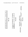
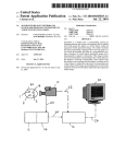
TAPE PRINTING APPARATUS
130
I10
120
/
/
CPU
‘ ’
/
RoIvI
RAM
A
<
i
/
KEYBOARD
25
I/
CUTTER MoToR
/
CHARACTER
DISPLAY
STORAGE AREA
SCREEN
A
i
I 26
V
i 3
41
L31
/
TAPAEISESFQING
‘
23
TAPE CUTTER /
V
150
' >
t5
,_ _____ ___/'_ ______ ___,
I CARTRIDGE LOADING I
;l sECTIoN
l
5
.
I
3
I
: TAPE IDENTIFICATION L 27
SENSOR
Patent Application Publication
Sep. 29, 2011 Sheet 1 0f 8
US 2011/0236104 A1
/
41/
Patent Application Publication
Sep. 29, 2011 Sheet 4 0f 8
US 2011/0236104 A1
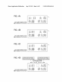
FIG. 4A
1h EB XEMYAMADA TARo)
432% éizémsATo KOTARO)
FIG. 4B
IJJEB KEMYAMADA TARo)
{7.5% #KEK (SATU KOTARO)
FIG. 4G
I
IJJEB KEMYAMADA TARO)
j
' -
‘
g i“
\L
‘
3
115% %7KEB(SAT0 KOTARO)
FIG. 4D
JUSTIFiCATIONrNON-TARGET
JUSTiFlCATIOMNON-TARGET
CHARACTER SPACING: NORMAL
CHARACTER SPACING: NORMAL
:
JUSTlFlCATION: TARGET
i
l
l
l
L
111 E5 XEMYAMADA TARO)
{25% %7KH$(SATO KOTARO)
s
|
I
J
Patent Application Publication
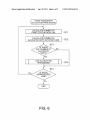
Sep. 29, 2011 Sheet 6 0f 8
US 2011/0236104 A1
START PARAGRAPH
ALLOCATION PROCESSING
CALCULATE NUMBER OF
PRINT DOTS IN EACH LINE
\S11
If
CALCULATE NUMBER OF
ALLOCATED DOTS IN TARGET LINE
\
S12
IS THERE
ANY NUMBER OF
ALLOCATED
DOTS?
LINE ALLOCATION
PROCESSING
\"S1 4
S15
IS THERE
UNPROCESSED
LINE?
FIG. 6
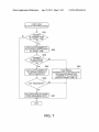
Patent Application Publication
Sep. 29, 2011 Sheet 7 0f 8
US 2011/0236104 A1
START LINE
ALLOCATION PROCESSING
NUMBER
OF CHARACTERS
IN TARGET LINE
> O?
CALCULATE NUMBER OF
ALLOCATED CHARACTERS \822
IN TARGET LINE
NUMBER
OF ALLOCATED
CHARACTERS
> 0?
S25
S24
/
CALCULATE NUMBER OF
ALLOCATED DOTS IN
EACH CHARACTER
v
/
CENTERING
(NUMBER 0F ALLOCATED DOTS
IN LEADING CHARACTER
= NUMBER OF ALLOCATED
DOTS IN TARGET LINE / 2)
ANY REMAINDER?
ALLOCATE ONE DOT EACH
FROM REMAINING DOTS \S27
II II
FIG. 7
Patent Application Publication
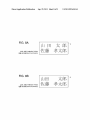
FIG. 8A
m EH icé? (YAMADA TARO)
ii? immsmo KOTARO)
FIG. 8B
m EH XEMYAMADA TARO)
{25E $7KEMSATO KOTARO)
Sep. 29, 2011 Sheet 8 0f 8
US 2011/0236104 A1
Sep. 29, 2011
US 2011/0236104 A1
TAPE PRINTING APPARATUS, CHARACTER
arrangement deciding method for the tape printing apparatus,
ARRANGEMENT DECIDING MEHTOD FOR
and a program for the same can be provided.
TAPE PRINTING APPARAUS, AND
PROGRAM FOR THE SAME
BACKGROUND
[0001]
[0002]
1. Technical Field
The present invention relates to a tape printing appa
ratus that can create a paragraph including plural lines of
character strings and print the paragraph on a tape, a character
arrangement deciding method for the tape printing apparatus,
and a program for the same.
[0003]
[0004]
2. RelatedArt
Traditionally, a tape printing apparatus of this kind
can provide several paragraphs on one label and thus can
provide various different numbers of lines or change design
for each paragraph. Also, justi?cation is knoWn as an attribute
(paragraph style) that can be set for each paragraph. This
justi?cation is the function of aligning other lines to the length
of the longest line in the paragraph, for example, as described
in the User’s Manual of “TEPRA” PRO SR930 by KING JIM,
July 2009, Third Edition, pages 73, 82.
[0005] When this justi?cation function is used, if different
lines have different numbers of characters, there is a problem
that the character spacing spreads in a line With a small
[0009]
According to an aspect of the invention, there is
provided a tape printing apparatus including: a paragraph
creating unit Which creates a paragraph including plural lines
of character strings; a justi?cation setting unit Which sets
justi?cation to evenly allocate other lines to the same length
as a longest line, of the plural lines in the paragraph; a char
acter mode setting unit Which sets a non-target range to be a
non-target of the justi?cation, on a character basis Within the
paragraph, and sets a length of character spacing Within the
non-target range; a character arrangement deciding unit
Which carries out justi?cation based on the justi?cation set
ting unit in a target range excluding the non-target range set
by the character mode setting unit, and thus decides an
arrangement of characters in each line included in the para
graph; and a printing unit Which prints the paragraph on a tape
With the character arrangement decided by the character
arrangement deciding unit.
[0010]
According to another aspect of the invention, there
is provided a character arrangement deciding method for a
tape printing apparatus that can print a paragraph including
plural lines of character strings. The method includes alloW
ing the tape printing apparatus to: create the paragraph; set
justi?cation to evenly allocate other lines to the same length
number of characters, thus spoiling the appearance. FIG. 8A
as a longest line, of the plural lines in the paragraph; set a
shoWs the result of printing a label L Where the ?rst line
non-target range to be a non-target of the justi?cation, on a
“Hi BECKER ” (YAMADA TARO) is justi?ed in a similar
layout to the second line “[E?%f%ii§|l ” (SATO
KOTARO) (“_” indicating a halfWidth space). In this manner,
character spacing Within the non-target range; and carry out
justi?cation based on the justi?cation setting in a target range
excluding the non-target range that is set, and thus deciding an
arrangement of characters in each line included in the para
since the ?rst line has a smaller number of characters than the
second line, the ?rst line looks sparse as a Whole.
[0006] Thus, even in the case Where a paragraph is justi?ed,
the justi?cation of the character spacing betWeen some char
acters that look sparse can be canceled (made non-target),
thus narroWing the character spacing to improve the appear
character basis Within the paragraph, and set a length of
graph.
[0011] With these con?gurations, in a non-target range to
be a non-target of justi?cation set for a paragraph, the length
of character spacing can be set on a character basis. There
fore, the degree of freedom for character arrangement Within
ance. FIG. 8B shoWs the result of printing a label L Where the
the paragraph can be enhanced. Thus, even When the charac
justi?cation of the character spacing betWeen “I I I ” (YAMA)
ter spacing is excessively expanded by the justi?cation of the
and “ [3E ” (DA) and between “t ” (TA) and “ fl|5 ” (R0) in the
non-target range and the character spacing Within this range
paragraph, a range covering the un?tting part can be set as a
?rst line “In DECKER ” (YAMADA TARO) is canceled.
can be set to a desired length. Therefore, characters in each
[0007]
line included in the paragraph can be arranged With proper
HoWever, the tape printing apparatus described in
the User’s Manual of “TEPRA” PRO SR930 by KING JIM,
appearance.
July 2009, Third Edition, pages 73, 82, cannot provide other
setting than “close” character spacing for the character setting
character mode setting unit selects a length of character spac
in Which justi?cation is canceled. Therefore, there are only
tWo options, that is, making character strings Within the para
graph a target of justi?cation or making the character strings
as a non-target of justi?cation. The characters Within the
paragraph cannot necessarily be arranged as desired by the
user. That is, in the example shoWn in FIG. 8A and FIG. 8B,
[0012]
In the tape printing apparatus, it is preferable that the
ing Within the non-target range from plural candidates repre
senting relative lengths.
[0013]
With this con?guration, the length of character
spacing can be selected from plural candidates such as
“close , narroW , normal” and “Wide”. Thus, even a begin
ner can easily set the length of character spacing.
the character spacing betWeen “ll-I ” (YAMA) and “ EE ” (DA)
[0014]
and between‘di” (TA) and “R5” (R0) in the ?rst line
that the character mode setting unit sets a character mode
setting target character either as a starting character of the
non-target range or as a starting character of the target range,
as the setting of the non-target range.
“ [ll EH _l\‘f\'lg ” (YAMADA TARO) cannot be made narroWer
than in FIG. 8A and cannot be made longer than in FIG. 8B,
either, even if the user Wants such setting.
SUMMARY
[0008] An advantage of some aspects of the invention is
that a tape printing apparatus having a high degree of freedom
for the character arrangement Within a paragraph, a character
In the tape printing apparatus, it is also preferable
[0015] With this con?guration, a non-target range (and a
target range) can be set by character mode setting for each
character. For example, in a character string “ABCDE”, if the
character “B” is set as the starting character of the non-target
range, the character strings from “B” becomes the non-target
range. Thus, the invention can be realiZed simply by adding
Sep. 29, 2011
US 2011/0236104 A1
an option whether to make a character or characters a target of
justi?cation or not, to a character mode menu.
The tape cartridge C is removably loaded in the cartridge
that the character arrangement deciding unit carries out the
loading section 6 in the state where the open/close cover 21 is
opened. In the open/ close cover 21, a viewing window 21a is
formed which allows visual recognition of loading or non
justi?cation using the spacing between each character within
loading of the tape cartridge C in the state where the open/
the target range and a character immediately before the each
character.
[0017] With this con?guration, for example, in the case
close cover 21 is closed.
[0016]
In the tape printing apparatus, it is also preferable
where a character string “BCD” as a part of a character string
“ABCDE” is set as a target range, justi?cation can be realiZed
using the spacing between “A” and “B”, between “B” and
“C”, and between “C” and “D”. Since there is no character
immediately before the leading character in each line (the ?rst
character), the leading character does not become a target of
justi?cation even if this character is set as a target range.
[0018]
According to still another aspect of the invention,
there is provided a program causing a computer to execute
each operation of the character arrangement deciding method
for the tape printing apparatus.
[0019] Using this program, a character arrangement decid
ing method for a tape printing apparatus with a high degree of
freedom for character arrangement in a paragraph can be
realiZed.
BRIEF DESCRIPTION OF THE DRAWINGS
[0020]
The invention will be described with reference to the
accompanying drawings, wherein like numbers reference like
elements.
[0021]
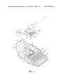
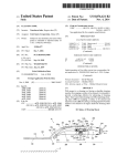
FIG. 1 is a perspective view showing the appearance
of a tape printing apparatus according to an embodiment of
the invention.
[0022] FIG. 2 is a control block diagram of the tape printing
apparatus.
[0023]
FIG. 3 is a screen transition view showing a series of
operations from the creation of a paragraph to the allocation.
[0024] FIG. 4A to FIG. 4D are explanatory views showing
the result of printing a label.
[0025] FIG. 5A to FIG. 5C are explanatory views showing
the setting of a character mode for each character, the number
of dots allocated to each character, and a calculation formula
for the same.
[0026]
FIG. 6 is a ?owchart showing paragraph allocation
by the tape printing apparatus.
[0027]
FIG. 7 is a ?owchart showing line allocation by the
tape printing apparatus.
[0028] FIG. 8A and FIG. 8A are explanatory views show
ing the result of printing a label according to a traditional
technique.
DESCRIPTION OF EXEMPLARY
EMBODIMENTS
[0029] Hereinafter, an embodiment of the invention will be
described with reference to the accompanying drawings. FIG.
1 is a perspective view showing the appearance of a tape
[0030]
A character key group 3a, and a function key group
3b to designate various operation modes or the like are
arranged on the keyboard 3. The character key group 311 has a
full key con?guration based on the JIS arrangement. The
character key group 311 is similar to the key con?guration of a
general word processor, including a shift key for restraining
increase in the number of keys to be operated. The function
key group 3b includes a “print” key, “cursor” keys, a “select”
key, a “delete” key, and an “edit” key.
[0031] The “print” key is a key for designating the execu
tion of printing. The “cursor” keys include up, down, left and
right keys (“'I‘”, “\|,”, “e”, “—>”). These keys are for cursor
movement and scrolling. The “select” key is a key for select
ing and ?naliZing an option. The “delete” key is a key for
deleting (or erasing) a character. The “edit” key is a key for
setting a character mode, setting a paragraph style, setting a
text format, and the like. A “paragraph” refers to an “aggre
gate of lines (or one line)” printed in a way that these lines are
stacked to the tape width. A “text” refers to all the paragraphs,
all the lines and all the characters printed on one label L (see
FIG. 4A to FIG. 4D). That is, the siZe of each unit is in
ascending order of "character<line<paragraph<text”.
[0032] The display screen 41 is a liquid crystal display and
is used by the user when con?rming an editing result based on
input information inputted via the keyboard 3 and print data
or the like generated on the basis of the editing result.
[0033] A tape discharge port 22 connecting the cartridge
loading section 6 to outside is formed at a left-side part of the
apparatus case 2. In the tape discharge port 22, a tape cutter 23
for cutting a tape T that is sent out exists. The tape T that is
already printed is sent out by a predetermined length from the
tape discharge port 22. In the state where the sending of the
tape is temporarily stopped, the printed tape T is cut by the
tape cutter 23. Thus, a stripe-like label L is created (see FIG.
4A to FIG. 4D). For the cutting processing, whether to drive
a cut motor 25 (see FIG. 2) can be set according to the option
to “carry out” or “not to carry out” automatic cutting.
[0034]
In the cartridge loading section 6, a head unit 61
having a thermal print head 7 built in a head cover 61a, a
platen drive shaft 62 facing the print head 7, a reel-in drive
shaft 63 which reels in an ink ribbon R, which will be
described later, and a positioning protrusion 64 for a tape reel
17, which will be described later, are provided. A tape feeding
motor 26 (see FIG. 2) which rotates the platen drive shaft 62
and the reel-in drive shaft 63 is built in a part below the
cartridge loading section 6.
[0035] The tape cartridge C houses a tape reel 17 on which
the tape T with a predetermined width (approximately 4 to 48
mm) is wound, at a top central part within a cartridge case 51,
printing apparatus 1 according to this embodiment, with its
and a ribbon reel 19 on which the ink ribbon R is wound, at a
open/close cover 21 opened. As shown in FIG. 1, the contour
of the tape printing apparatus 1 is formed by an apparatus case
bottom right part. The tape T and the ink ribbon R have the
2. A keyboard 3 having various input keys is arranged on the
top side of a front part of the apparatus case 2. The open/close
cover 21 is attached to a left part on the top side of a rear part.
A display screen 41 is arranged to the right of the open/close
cover 21. Inside the open/close cover 21, a cartridge loading
section 6 for loading a tape cartridge C is formed as a recess.
same width. A through-hole 55 in which the head cover 6111
covering the head unit 61 is to be inserted is formed at a left
part below the tape reel 17. With the head unit 61 inserted in
the through-hole 55, a platen roller 53 which is engaged with
the platen drive shaft 62 and thus rotationally driven is
arranged corresponding to the part where the tape T and the
ink ribbon R overlap each other. Meanwhile, a ribbon reel-in
Sep. 29, 2011
US 2011/0236104 A1
reel 54 is arranged closely to the ribbon reel 19. The ink
ribbon R reeled off from the ribbon reel 19 is arranged to
surround the head cover 6111 and becomes reeled in by the
ribbon reel-in reel 54.
storage area 131 in Which many characters used for the dis
play on the display screen 41 and the print on the tape T are
stored.
[0040] The display screen 41 functions as a display unit to
When the tape cartridge C is loaded in the cartridge
display the result of editing and print layout. The keyboard 3
loading section 6, the head cover 6111 is inserted in the
functions as an input unit for the user to input information, an
through-hole 55, the position protrusion 64 is inserted in the
editing unit to carry out editing processing, a setting unit to
carry out various kinds of setting, and the like.
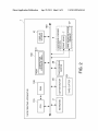
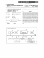
[0041] The cutter motor 25 is connected With the tape cutter
23 and functions as a cutting unit. The tape feeding motor 26
[0036]
center hole of the tape reel 17, and the reel-in drive shaft 63 is
inserted in the center hole of the ribbon reel-in reel 54. The
print head 7 is abutted against the platen roller 53, With the
tape T and the ink ribbon R nipped betWeen the print head 7
and the platen roller 53. Thus, printing becomes available.
printing on the tape T. As described above, the print head 7
After that, as the user inputs a desired text (characters includ
and the tape identi?cation sensors 27 are provided in the
ing letters, numbers, symbols and simple patterns) or image
cartridge loading section 6. The tape identi?cation sensors 27
detect the type of the tape T housed in the tape cartridge C.
via the keyboard 3 While con?rming the result of editing on
the display screen 41 and then presses the “print” key to
designate printing, the tape printing apparatus 1 reels off the
tape T from the tape cartridge C by the tape feeding motor 26
and causes a heat generating element of the print head 7 to
selectively generate heat, thus performing desired printing on
the tape T. The printed part of the tape T is sent outside, as
required, from the tape discharge port 22. When the printing
is completed, the tape feeding motor 26 feeds the tape T to a
position Where a tape length including a margin is obtained.
After that, the tape feeding motor 26 stops the feeding (and
then the apparatus shifts to cutting processing).
[0037] Meanwhile, the tape T includes a recording tape Ta
having an adhesive layer formed on its back side, and a
and the print head 7 function as a printing unit to carry out
The CPU 110 controls the limitations to the number of lines
and the number of characters that can be inputted as a text, the
determination of compatibility of the loaded tape cartridge C,
and the like, on the basis of the result of detection by the tape
identi?cation sensors 27 (on the basis of the tape Width and
the like). The CPU 110 also controls the display processing on
the display screen 41, the editing processing and the print
processing.
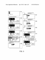
[0042] Next, the operations from the creation of a para
graph to the allocation, and the result of printing based on
these operations Will be described With reference to FIG. 3
and FIG. 4A to FIG. 4D. The screen indicated by a reference
separation tape Tb pasted to the recording tape Ta by the
symbol D01 (hereinafter referred to as “screen D**”) shoWs
adhesive layer. The tape T is Wound in the shape of a roll With
Tb facing inside, and is housed in the cartridge case 51.
a text input screen in a state Where no input is made yet. In the
text input screen in the state Where no input is made yet, a
cursor K is added to a beginning-of-line mark indicated by an
Different types of tapes T (With different tape Widths, tape
background colors, background patterns, materials and the
enclosed number. The beginning-of-line mark displayed in
White (the number representing the line number displayed in
like) are prepared. One of these types of tapes T (or ink
black) means that no character is inputted in this and subse
ribbons R) is housed in each cartridge case 51. On the back
quent lines. The beginning-of-line mark displayed in black
(the number representing the line number displayed in White)
the recording tape Ta facing outside and the separation tape
side of the cartridge case 51, plural holes (not shoWn) to
specify the type of the tape cartridge C are provided. In the
cartridge loading section 6, plural tape identi?cation sensors
(micro-sWitches or the like) 27 (see FIG. 2) to detect the plural
holes are provided corresponding to the plural holes. As the
tape identi?cation sensors 27 detect the state of the plural
holes, the tape type can be determined.
[0038] Next, the control con?guration of the tape printing
apparatus 1 Will be described With reference to the control
block diagram of FIG. 2. The tape printing apparatus 1 has a
CPU (central processing unit) 110, a RAM (random access
memory) 120, a ROM (read only memory) 130, the display
screen 41, the keyboard 3, the cutter motor 25, the tape cutter
23, the tape feeding motor 26, the print head 7, and the tape
identi?cation sensors 27. These components are connected
via a bus 150.
means that characters are inputted in this and subsequent lines
(see D02 or the like). On the bottom side of the text input
screen, there is a text display area shoWing inputted texts. On
the top side of the text input screen, there is a print previeW
area. Moreover, at a top left part of the screen, there is a siZe
display area shoWing the siZe of a label L to be produced. For
example, in the example shoWn in FIG. 3, since no input is
made yet, it is shoWn that the tape length is 0.0 mm and the
tape Width is 18 mm on the basis of the result of detection by
the tape identi?cation sensors 27.
[0043] A screen D02 shoWs a state Where characters of the
?rst paragraph are inputted. Here, it is assumed that “Ill Ell-5”
(YAMADA TARO) is inputted in the ?rst line
and “1E Haitian” (SATO KOTARO) is inputted in the
The RAM 120 is directly connected With the CPU
second line (“_” meaning a halfWidth space) (paragraph cre
110 and is used as a Work area When the CPU 110 carries out
ating unit). Here, if the “edit” key is pressed and “allocation:
various kinds of control. The ROM 130 stores control pro
grams and various kinds of information for carrying out vari
justi?cation” is set as the paragraph style, the screen D03 is
[0039]
ous kinds of control. Speci?cally, as the control programs, a
display control program to control the display on the display
displayed (justi?cation setting unit). In the screen D03, a state
Where other lines (in this example, the ?rst line) are evenly
allocated to the same length as the longest line (in this
example, the second line) of the lines included in the para
screen 41, a paragraph creation processing program to create
a paragraph, a paragraph allocation processing program to
carry out allocation processing Within a paragraph, a print
graph, is displayed in the print previeW area. The result of
printing a label L that is produced When the “print” key is
processing program to carry out print processing, and the like
pressed in the state of the screen D03 is as shoWn in FIG. 4A.
are stored (not shoWn). The ROM 130 also has a character
The setting of the paragraph style is not described in detail.
Sep. 29, 2011
US 2011/0236104 A1
However, this setting is carried out as an editing item selec
tion screen shown in a screen D05 is displayed by the opera
tion of the “edit” key.
[0044] Next, the operation to cancel, on a character basis,
the justi?cation set for the paragraph and then set character
spacing will be described (character mode setting unit). If the
cursor K is moved to the character “II-I ” (YAMA) by the
operation of the “cursor” keys in the state of the screen D03,
a screen D04 is displayed. If the “edit” key is pressed in the
state of the screen D04, the editing item selection screen
(screen D05) is displayed. Here, if the cursor K is moved to
“justi?cation”, of the plural editing items in the character
mode (font, decorated character, italic and highlight, enlarge
and reduce, enclose and shade, justi?cation, end?) and the
“select” key is pressed, a justi?cation setting screen (screen
D06) is displayed. The justi?cation setting screen is a screen
for setting whether to make a particular part a target of the
and setting the character “E15 ” (R0) to “justi?cation: non
target”i“character spacing: normal”, following the screen
D05 to the screen D09. In the screen D11, three character
mode marks M1, M2 and M3 indicating that the character
mode is set are displayed in the text display area, and the
result of the above setting is displayed in the preview display
area. The result of printing a label L that is produced in the
case where the “print” key is pressed in the screen D11 is as
shown in FIG. 4C.
[0050] As shown in FIG. 4A to FIG. 4D, the result of
printing shown in FIG. 4C has an improved appearance
because the character spacing between “I I I ” (YAMA) and
“ EE ” (DA) and between “i ” (TA) and “ EB ” (R0) in the ?rst
line “III [UijKE'IB ” (YAMADA TARO) is narrower than in
FIG. 4A where only justi?cation for the paragraph is carried
justi?cation for the paragraph or not. That is, with the setting
out. This improvement in appearance can be realiZed since the
on this screen, it is possible to set a justi?cation non-target
range. Here, if the cursor K is moved to an item “non-target”
character spacing between “ II-I ” (YAMA) and “ EE ” (DA) and
and the “select” key is pressed, a character spacing setting
screen (screen D07) is displayed.
[0045] The character spacing setting screen is a screen for
setting character spacing in the case where the item “non
target” is selected on the justi?cation setting screen.
[0046] In the character spacing setting screen, character
spacing can be selectively set from among plural candidates
indicating relative lengths. Here, if the cursor K is moved to
an item “normal” and the “select” key is pressed, a screen D08
for selecting an item in the character mode is displayed. If the
cursor K is moved to the item “end?” meaning the end of
editing in the character mode, in the screen D08, and the
“select” key is pressed, a screen D09 for selecting a valid
range of the editing content is displayed.
[0047]
In the screen D09, either an item “entire text” or an
item “from this character” can be selected. For example, if
“entire text” is selected, the editing content is re?ected on the
entire text. Meanwhile, if “from this character” is selected,
the editing content is re?ected on that character and the sub
sequent characters (the position of the cursor K and the sub
sequent part). That is, when the item “from this character” is
selected, the character that is the setting target (in this
between “i ” (TA) and “ E15 ” (RO) is set to “justi?cation:
non-target” and further to “character spacing: normal”, as
shown in FIG. 4D. In FIG. 4C, the character spacing between
“ I3E ” (DA) and “_” (indicated by a dotted-line frame in FIG.
4C) and between “_” and “7K ” (TA), which is set to “justi?
cation: target”, is widened as the character spacing between
“in ” (YAMA) and “ EE ” (DA) and between “i ” (TA) and
“EB ” (RO) is narrowed. Hereinafter, this allocation process
ing will be described in detail.
[0051] FIG. 5A shows the setting of the character mode
“justi?cation” for the ?rst line “II-I ELK?!“ ” (YAMADA
TARO) in the case where the setting shown in FIG. 3 is carried
out. As described above, in the character mode, a target or
non-target of justi?cation for a paragraph can be set on a
character basis. In the example shown in FIG. 3, the charac
ters “II-I ” (YAMA), “_” and “ii ” (TA) are set to “allocation:
target” and the characters “ EE ” (DA) and “ FIB ” (R0) are set to
“allocation: non-target”. In the following description, a char
acter set to “allocation: target” is referred to as a “target
characters”, and a character set to “allocation: non-target” is
example, “IEE ” (DA)) is set as the starting character of a
referred to as a “non-target character”.
non-target range. If the item “target” is selected in the justi
?cation setting screen (screen D06) and the item “from this
[0052] FIG. 5B shows the number of allocated dots that are
allocated to each character in the ?rst line “Ill EELiQEIIS ”
character” is selected in the screen D09, the character that is
the setting target is set as the starting character of a target
range.
[0048] If the cursor K is moved to the item “from this
character” in the screen D09 and the “select” key is pressed,
a text input screen of a screen D10 is displayed. In the screen
D10, a character mode mark M1 (black right-pointing trian
gular mark) indicating that the character mode is set is dis
played in the text display area. With this display, the user can
con?rm that the character mode is set on the character “ EE ”
(DA) and the subsequent characters. Also, in the screen D10,
a state where the character spacing between the characters
“I I I ” (YAMA) and “ EE ” (DA) is set to “normal” is displayed
in the preview display area. The result of printing a label L
that is produced in the case where the “print” key is pressed in
(YAMADA TARO) in the case where the setting shown in
FIG. 3 is carried out. In this embodiment, the number of dots
represents the length in the longitudinal direction of the tape
T. The number of allocated dots represents dots allocated to
target characters other than the leading character. Therefore,
in the example shown in FIG. 3, n dots are allocated to each of
the characters “_” and “X ” (TA). That is, justi?cation is
carried out using the spacing between each character within
the target range and the character immediately before this
each character. Thus, since there is no character immediately
before the ?rst character of each line, the ?rst character of
each line does not become a target of justi?cation even when
this character is set within a target range. Therefore, even
when the leading character is set as a target character as in this
example, no dots are allocated to the leading character. Thus,
the screen D10 is as shown in FIG. 4B.
misalignment of the head position from other lines and
[0049]
appearance and the resulting poor appearance can be pre
vented.
A screen D11 is the display screen 41 (text input
screen) after setting the character “ ” to “justi?cation: target”
Sep. 29, 2011
US 2011/0236104 A1
[0053] FIG. 5C shows a calculation formula for calculating
the number of allocated dots n. As shown in FIG. 5C, the
number of allocated dots n that are allocated to each character
is the value of “the number of allocated dots in each line”
divided by “the number of allocated characters in each line”.
“The number of allocated dots in each line” is the number of
dots obtained by subtracting the number of dots in each line
from the number of dots in the longest line of the plural liens
included in the paragraph. “The number of allocated charac
ters in each line” is the number obtained by subtracting 1 from
the number of characters in each line and then further sub
tracting the number of non-target characters from the result.
[0054] Next, allocation processing by the tape printing
apparatus 1 (character arrangement deciding unit) will be
described with reference to the ?owcharts of FIG. 6 and FIG.
7. FIG. 6 is a ?owchart showing paragraph allocation pro
cessing. The tape printing apparatus 1 (CPU 110) calculates
the number of print dots in each line included in a paragraph
(S11). Next, the tape printing apparatus 1 calculates the num
two character spacings indicated as “justi?cation: target” in
FIG. 4C. If there isn’t any number of remaining dots (No in
S26), S27 is omitted and the line allocation processing ends.
[0058] As described above, with the tape printing apparatus
1 according to the embodiment, the length of character spac
ing can be set on a character basis in a non-target range to be
a non-target of justi?cation that is set for a paragraph. There
fore, the degree of freedom for the character arrangement
within the paragraph can be enhanced. Thus, even in the case
where the character spacing is excessively expanded by the
justi?cation of the paragraph, a range covering the un?tting
part can be set as a non-target range and the character spacing
within this range can be set to a desired length. Therefore,
characters in each line included in the paragraph can be
arranged with proper appearance. Moreover, since the length
of character spacing can be selected from plural candidates
indicating relative lengths such as “close”, “narrow”, “nor
mal” and “wide”, even a beginner can easily set the length of
character spacing.
ber of allocated dots in a target line to be a target of allocation
[0059]
(S12). The number of allocated dots in the target line is
equivalent to “the number of allocated dots in each line shown
selected from plural candidates indicating relative lengths.
However, it is also possible to enable the setting of the char
in FIG. 5C. Here, if there is a certain number of allocated dots
acter spacing by inputting numeric values (character mode
in the target line (Yes in S13), line allocation processing is
setting unit). In this case, values may be inputted in any unit,
for example, in inches, in millimeters, or in dots.
[0060] In the embodiment, in the case where “justi?ca
tioninon-target” is set in the character mode, the character
carried out (S14). If there isn’t any number of allocated dots
in the target line (No in S13), S14 is omitted. After that, it is
determined whether there is an unprocessed line or not (S15).
If there is an unprocessed line (Yes in S15), the processing
In the embodiment, the character spacing can be
paragraph allocation processing ends.
spacing can be set as its lower hierarchical level (see the
screen D06 and the screen D07 in FIG. 3). However, it is also
possible to enable the setting of the character spacing as an
[0055]
editing item in the character mode. That is, it is possible to
returns to S11. If there is no unprocessed line (No in S15), the
FIG. 7 is a ?owchart showing the line allocation
processing equivalent to S14 in FIG. 6. The tape printing
apparatus 1 (CPU 110) determines whether the number of
characters in the target line is greater than 0 or not (S21). If the
number of characters in the target line is not greater than 0 (No
in S21, there is no character in the target line), the line allo
cation processing ends. If the number of characters in the
target line is greater than 0 (Yes in S21, there are characters in
the target line), the number of allocated characters in the
target line is calculated (S22). The number of allocated char
acters in the target line is equivalent to “the number of allo
cated characters in each line” shown in FIG. SC.
[0056] After that, it is determined whether the number of
allocated characters in the target line is greater than 0 or not
(S23). If the number of allocated characters in the target line
is not greater than 0 (No in S23, there is no allocated charac
ter), the target line is centered (S24). For example, a case
where all the characters in the target line are set as non-target
characters is equivalent to this case. In this case, the number
of allocated dots in the leading character is calculated by
dividing the number of allocated dots in the target line by 2.
[0057] Meanwhile, if the number of allocated characters in
the target line is greater than 0 (Yes in S23, there are allocated
characters), the number of allocated dots in each character is
calculated (S25). The number of allocated dots in each char
acter can be calculated according to the calculation formula
shown in FIG. 5C. After that, it is determined whether there is
any number of remaining dots or not (S26). If there is a certain
number of remaining dots (Yes in S26), the remaining dots are
allocated, one dot each, to each target character (each char
acter spacing). That is, one dot each from the remaining dots
enable the selection of an editing item “character spacing” on
the editing item selection screen (screen D05).
[0061] In the embodiment, justi?cation is carried out using
the spacing between each character within a justi?cation tar
get range and the character immediately before that character.
However, the spacing between each character within a justi
?cation target range and the character immediately after that
character may also be used. In other words, dots in the number
of allocated dots may be allocated to the character spacing
between a target character and the following character,
instead of allocating the dots to the character spacing between
the target character and the preceding character. It is also
possible to enable the user to set whether to allocate the dots
before or after the target character.
[0062] In the embodiment, as a method for setting a justi
?cation non-target range, in the case where the item “non
target” is selected on the justi?cation setting screen (screen
D06) and the item “from this character” is selected on the
screen D09 for setting an effective range of the character
mode, a character that is the setting target is set as the starting
character of the non-target range. However, it is also possible
to enable the setting of the ending character of the non-target
range instead of the starting character of the non-target range.
That is, in the case where the item “non-target” is selected on
the justi?cation setting screen (screen D06) and the item “to
this character” is selected on the screen D09, a character that
is the setting target may be set as the ending character of the
non-target range.
[0063]
In the embodiment, the start or end of a non-target
range can be set on a character basis by the character mode
is allocated to each of the characters “_” and “i! ” (TA), thus
setting for each character. However, it is also possible to
aligning the leading end and the terminal end of the line. This
enable the setting of the starting position and the ending
allocation means that the remaining dots are allocated to the
position of the non-target range by a series of operations. That
Sep. 29, 2011
US 2011/0236104 A1
is, for the setting of the non-target range, the cursor K may be
a printing unit Which prints the paragraph on a tape With the
moved to designate the starting position and then the “cursor”
character arrangement decided by the character arrange
ment deciding unit.
2. The tape printing apparatus according to claim 1,
Wherein the character mode setting unit selects a length of
character spacing Within the non-target range from plural
keys may be operated to designate the ending position.
[0064] The components of the tape printing apparatus 1
described in the embodiment can be provided as a program.
Also, the program stored in various recording media (CD
ROM, ?ash memory and so on) can be provided. That is, a
program Which causes a computer to function as each unit of
the tape printing apparatus 1, and a recording medium in
Which this program is recorded should also be included in the
scope of right of the invention. Moreover, various changes
and modi?cations can be made Without departing from the
scope of the invention.
[0065] This invention can be used for a tape printer con
nected to a personal computer, the personal computer
remotely control the tape printer.
[0066] The entire disclosure of Japanese PatentApplication
No. 2010-67229, ?led Mar. 24, 2010, is expressly incorpo
rated by reference herein.
What is claimed is:
1. A tape printing apparatus comprising:
a paragraph creating unit Which creates a paragraph includ
ing plural lines of character strings;
a justi?cation setting unit Which sets justi?cation to evenly
allocate other lines to the same length as a longest line,
of the plural lines in the paragraph;
a character mode setting unit Which sets a non-target range
to be a non-target of the justi?cation, on a character basis
Within the paragraph, and sets a length of character
spacing Within the non-target range;
a character arrangement deciding unit Which carries out
justi?cation based on the justi?cation setting unit in a
target range excluding the non-target range set by the
character mode setting unit, and thus decides an arrange
ment of characters in each line included in the para
graph; and
candidates representing relative lengths.
3. The tape printing apparatus according to claim 1,
Wherein the character mode setting unit sets a character mode
setting target character either as a starting character of the
non-target range or as a starting character of the target range,
as the setting of the non-target range.
4. The tape printing apparatus according to claim 1,
Wherein the character arrangement deciding unit carries out
the justi?cation using the spacing betWeen each character
Within the target range and a character immediately before the
each character.
5. A character arrangement deciding method for a tape
printing apparatus that can print a paragraph including plural
lines of character strings, the method comprising:
creating the paragraph;
setting justi?cation to evenly allocate other lines to the
same length as a longest line, of the plural lines in the
paragraph;
setting a non-target range to be a non-target of the justi?
cation, on a character basis Within the paragraph, and set
a length of character spacing Within the non-target
range; and
carrying out justi?cation based on the justi?cation setting
in a target range excluding the non-target range that is
set, and thus deciding an arrangement of characters in
each line included in the paragraph.
6. A program causing a computer to execute the operation
of the character arrangement deciding method for the tape
printing apparatus according to claim 5.
*
*
*
*
*