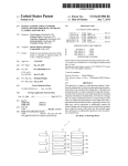
1
US 20100322640A1
(19) United States
(12) Patent Application Publication (10) Pub. No.: US 2010/0322640 A1
Yamada
(43) Pub. Date:
(54) IMAGE FORMING DEVICE, A FAILURE
(30)
Dec. 23, 2010
Foreign Application Priority Data
PREDICTION METHOD EXECUTED BY AN
IMAGE FORMING DEVICE, AND A
Jun. 19, 2009
COMPUTER READABLE STORAGE MEDIUM
STORING A PROGRAM FOR CONTROLLING
AN IMAGE FORMING DEVICE
(JP) ............................... .. 2009-146816
Publication Classi?cation
(51)
Int- Cl
(52)
us. Cl. ........................................................ .. 399/11
G03G 15/00
_
(75) Inventor:
_
Kei Yamada, Atsug1-sh1 (JP)
(57)
(2006.01)
ABSTRACT
Correspondence Address:
The image forming device according to the present invention
BUCHANAN, INGERSOLL & ROONEY PC
POST OFFICE BOX 1404
capacity storage device is provided. The image forming
can making accurate failure prediction Without using a high
device has a detecting unit for detecting certain abnormality
Which portends a breakdown of the image forming device
ALEXANDRIA, VA 22313-1404 (US)
(73) Assignee:
itself, an instructing unit for instructing user about an opera
tion test on the region Where the abnormality has been
KONICA MINOLTA BUSINESS
detected by the detecting unit (S201), a testing unit for per
forming the operation test on the region With assistance of the
TECHNOLOGIES, INC.,
Chiyoda-ku (JP)
user Who has been instructed by the instructing unit (S203), a
(21) Appl. No.:
12/817,402
measuring unit for measuring values describing the current
status of the region during the operation test by the testing unit
(S204), and a predicting unit for conducting the failure pre
(22) Filed:
Jun. 17, 2010
measuring unit (S205).
diction on the region based on the valued measured by the
Failure prediction
Start
S1 01
Paper jam
detected?
S102
Store sensor data
8103
Spot paperjam occurrence region
8104
Download suitable script
S105
action completed?
S106
Script execution
l
Recovery
Patent Application Publication
Dec. 23, 2010 Sheet 1 of 10
US 2010/0322640 A1
F|G.1
E
4
5
2
2
Remote control
system
xternal server
N
2
PC
MFP
---------------
1
3
'\
A
2
H62
1
11 \
/ 14
Control unit
Input unit
Storage unit
Network interface
12 \
f 15
13 \
Display unit
\16
Patent Application Publication
Dec. 23, 2010 Sheet 2 0f 10
US 2010/0322640 A1
2
21
\
.
Control umt
Image scanning
unlt
Storage unit
Printing unit
Operating unit
Network interface
23 \
/
24
f 26
Patent Application Publication
Dec. 23, 2010 Sheet 3 0f 10
FIG-.4
Failure prediction
Start
S101
S102
Store sensor data
S103
Spot paper jam occurrence region
S104
Download suitable script
S105
action completed?
Recovery
YES
S106
Script execution
End
US 2010/0322640 A1
Patent Application Publication
Dec. 23, 2010 Sheet 4 0f 10
US 2010/0322640 A1
Script execution
(S106)
S201
Instruct user about preparation
work for paper feeding test
3202
Preparation work
completed?
YES
8203
Perform paper feeding test
S204
Store sensor data
S205
Conduct failure prediction
based on sensor data
High failure
8206
NO
probability?
YES
8207
Send information to
remote control system
S208
Determine restricted function
S209
Set restriction ?ag
(
Return
)
Patent Application Publication
Dec. 23, 2010 Sheet 5 0f 10
US 2010/0322640 A1
Function restriction
Start
S301
Obtain function restriction ?ag
3302
Any restricted function?
S303
Display warning message
S304
Receive copying instruction
Restricted
function selected?
5306
Display warning message
S307
Proceeding with copying?
YES
S308
Start copying
End
NO
Patent Application Publication
Dec. 23, 2010 Sheet 6 0f 10
US 2010/0322640 A1
Function restriction
Start
S401
Obtain restricted function flag
NO
S402
Any restricted“?
YES
S403
Display warning message
S404
Receive print instruction
Restricted
function selected?
S406
Displays warning message
S407
Continue printing?
YES
S408
Order MFP to start printing
End
Patent Application Publication
Dec. 23, 2010 Sheet 7 0f 10
US 2010/0322640 A1
$58V660532
.
o2
558*2>981
mmRQ“o?m
éelaog
Patent Application Publication
Dec. 23, 2010 Sheet 8 0f 10
US 2010/0322640 A1
858625:2
2622%he_89$\Q:.532§8>%9
22525%2%825m
$vm moaoa 502
Patent Application Publication
Dec. 23, 2010 Sheet 10 0f 10
5
23E25%N95A
US 2010/0322640 A1
5£3895 A013A365% CcQ2AG6Ew5 cE52:065
N“E:$228A
3
sm85t:wql
.56AAm55Aic6o8;tm%q 3%5mg8@:98390
NE298m85:38
AW
A2
N@A:92:528
2 6E
.@5 85
:5QG6Ew5Q S958a5uce
CNmHA8EI9oEt2m8Q AugEEmma2%2652
US 2010/0322640 A1
IMAGE FORMING DEVICE, A FAILURE
PREDICTION METHOD EXECUTED BY AN
IMAGE FORMING DEVICE, AND A
COMPUTER READABLE STORAGE MEDIUM
STORING A PROGRAM FOR CONTROLLING
AN IMAGE FORMING DEVICE
Dec. 23, 2010
the region Where the abnormality has been detected by the
detecting unit. The testing unit performs the operation test on
the region With assistance of the user Who has been instructed
by the instructing unit. The measuring unit measures values
Which describe the current status of the region during the
operation test by the testing unit. Finally, the predicting unit
makes failure prediction on the region based on the values
CROSS-REFERENCE TO RELATED
APPLICATION
[0001]
This application is based on Japanese Patent Appli
cation No. 2009- 1 468 1 6, ?led on Jun. 19, 2009, the contents
of Which are incorporated herein by reference.
BACKGROUND
[0002] 1. Technical Field
[0003] The present invention relates to an image forming
device that is capable of making failure prediction on its
various regions, a failure prediction method executed by the
measured by the measuring unit.
[0011] Preferably, the image forming device further com
prises a ?rst communication unit for doWnloading a failure
prediction program from an external server, and the predict
ing unit makes the failure prediction using the program doWn
loaded by the ?rst communication unit.
[0012]
Preferably, the ?rst communication unit selectively
doWnloads the failure prediction program according to the
type of the abnormality detected by the detecting unit.
[0013] Preferably, the image forming device further com
prises a display unit for displaying the result of the failure
prediction by the predicting unit. Preferably, the display unit
image forming device, and a computer-readable recording
forms apart of an operation panel of the image forming
medium storing a control program for the image forming
device.
device.
[0014] Preferably, the image forming device further com
prises a function restriction determining unit for determining
function restriction to be imposed on the image forming
device, from the result of the failure prediction by the pre
dicting unit, and the operation panel displays information on
the function restriction determined by the function restriction
[0004]
[0005]
2. Description of RelatedArt
In recent years, MFP’s improved performance
enabled its shared use by many users, and thereby resulted in
reduction of its introduction cost. HoWever, such shared use
of a MFP could possibly cause all the users a lot of trouble if
the MFP stops operation due to a failure. Hence there is high
demand for failure prediction technologies Which alloW for an
accurate prediction of the time When failures is likely to occur
in a MFP, so that it can be properly maintained or repaired
before breaking doWn.
[0006] Previously, the most commonly-used method of
determining unit.
[0015] Preferably, the operation panel displays a Warning
message for advising user not to use the function affected by
the function restriction determined by the function restriction
determining unit if it is selected by user.
[0016]
Preferably, the image forming device further com
MFP’s failure prediction Was to store a set of data measured
by sensors installed in various regions Within a MFP into a
prises a second communication unit for sending information
on the function restriction determined by the function restric
high-capacity storage device like a hard disk, and statistically
analyZe chronological change in the measured data. For
example, the Japanese Unexamined Publication No. 2007
tion determining unit, to a printer driver for con?guring print
settings of the image forming device, so that the printer driver
256356 discloses a failure prediction method Which includes
can display information on the function restriction on its print
setting screen.
calculating an abnormality index value for the most-recently
[0017]
acquired data set from normal data sets stored in a hard disk,
Which have been obtained at certain intervals.
diction based on the values measured at the time When the
[0007]
HoWever, the conventional technology described
Preferably, the predicting unit makes the failure pre
abnormality has been detected by the detecting unit.
[0018] Preferably, the image forming device further com
above has a defect in its high introduction cost due to the
prises a third communication unit for sending information on
necessity for a high-capacity hard disk. Moreover, this tech
the result of the failure prediction by the predicting unit, to an
external control system.
[0019] The objects, features, and characteristics of this
nology only involves periodical acquisition of normal data,
and hence it does not make use of abnormal data correspond
ing to MFP’s malfunctions like a paper jam Which portend a
MFP failure although analysis of such abnormal data are
knoWn to be effective in accurate failure prediction.
[0008] The present invention is intended to solve the above
mentioned problems in the prior art, and its object is to pro
vide an image forming device capable of highly-accurate
failure prediction Without the necessity for a high-capacity
storage device.
SUMMARY
[0009]
To achieve at least one of the above-mentioned
objects, an image forming device re?ecting an aspect of the
present invention comprises a detecting unit, an instructing
unit, a testing unit, a measuring unit, predicting unit.
[0010] The detecting unit detects certain abnormality
Which portends a breakdoWn of the image forming device.
The instructing unit instructs user about an operation test on
invention other than those set forth above Will become appar
ent from the description given beloW With reference to pre
ferred embodiments illustrated in the accompanying draW
mgs.
BRIEF DESCRIPTION OF THE DRAWINGS
[0020]
FIG. 1 is a block diagram shoWing an exemplary
structure of the failure prediction system including the image
forming device according to one embodiment of the present
invention.
[0021] FIG. 2 is a block diagram shoWing an exemplary
structure of the PC shoWn in FIG. 1.
[0022] FIG. 3 is a block diagram shoWing an exemplary
structure of the MFP shoWn in FIG. 1.
[0023] FIG. 4 is a ?owchart shoWing exemplary steps of the
failure prediction according to one ?rst embodiment of the
present invention.
US 2010/0322640 A1
Dec. 23,2010
for controlling PC 1’s basic operations, a RAM for tempo
[0024] FIG. 5 is a ?owchart showing exemplary steps of the
script execution according to one embodiment of the present
invention.
[0025] FIG. 6 is a ?owchart showing exemplary steps for
the function restriction for the copying function according to
rarily storing control programs to serve as a working area, and
a hard disk for storing an OS (operating system or basic
software) as well as control programs and parameters for
one embodiment of the present invention.
The hard disk of the storage unit 12 particularly stores various
[0026] FIG. 7 is a ?owchart showing exemplary steps for
the function restriction for the print function according to one
embodiment of the present invention.
[0027] FIG. 8 is a schematic view of the copying setting UI
applications for producing document ?les, and a printer
driver for con?guring MFP 2’s print function.
screen according to an embodiment of the present invention.
kinds of information to the user who tries to operates the PC
[0028]
1. The display unit 13 particularly displays an UI (User Inter
face) screen for print settings, which is offered by the afore
FIG. 9 is a schematic view of the copying setting UI
screen according to one embodiment of the present invention.
[0029]
FIG. 10 is a schematic view of the print setting UI
screen according to one embodiment of the present invention.
[0030] FIG. 11 is a schematic view for illustrating the
advantageous effects according to one embodiment of the
present invention.
DETAILED DESCRIPTION
[0031] The embodiment of this invention is described
below with reference to the accompanying drawings.
<System Structure>
[0032]
FIG. 1 is a block diagram showing an exemplary
structure of a failure prediction system in which an MFP 2
serves as an image forming device according to the embodi
ment of the present invention. As shown in FIG. 1, the failure
prediction system according to the embodiment includes an
image forming system A, an external server 4, and a remote
control system 5, all of which are connected one another via
a network N so that they are capable of interactive commu
nications. The network N can be a public communication
network such as ISDN or CATV, a computer network such as
controlling PC 1’s speci?c operations to be described later.
[0037]
The display unit 13 is a display device such as a CRT
display and a liquid crystal display, and displays various
mentioned printer driver. FIG. 9 is an schematic view of the
print setting UI screen “u”.
[0038] The input unit 14 includes a keyboard and a mouse
for acquiring various instructions from user. The communi
cation interface 15 is an interface for communicating with the
MFP 2 via the LAN 3, and is typically a network interface to
a standard such as Ethernet®, TokenRing, and FDDI, a serial
interface such as USB and IEEE 1394, a parallel interface
such as SCSI and IEEE 1284, etc.
[0039] FIG. 3 is a block diagram showing an exemplary
structure of the MFP 2. As shown in FIG. 3, the MFP 2
includes a control unit 21, a storage unit 22, an operating unit
23, an image scanning unit 24, a printing unit 25, and a
communication interface 26, all of which are interconnected
via a bus 27 for exchanging signals. These elements are be
described in details below.
[0040] The control unit 21 is a CPU for not only performing
various calculations, but also controlling each of the elements
according to various control programs. The storage unit 22
includes a ROM for storing control programs and parameters,
a RAM for temporarily storing control programs to serve as a
working area, and a hard disk for storing an OS (operating
LAN, WAN and Internet, or a dedicated circuit to be used
system or basic software) as well as control programs and
exclusively by users of the system.
[0033] As shown in FIG. 1, the image forming system A
parameters for controlling MFP 2’s speci?c operations as
includes a PC 1 which serves as a client device, and the MFP
described later.
[0041] The operating unit 23 includes a touch panel which
is capable of not only displaying MFP 2’s status and various
2 which serves as an image forming device having functions
to print the data received from the PC 1 and to copy various
documents, and they are connected with each other by a LAN
kinds of setting information, but also receiving various
3 for their interactive communications. The image forming
includes various ?xed keys such as ten-keys for receiving the
system A is connected to the network N via the LAN 3. The
number of copies, Start & Stop keys for receiving instructions
LAN 3 includes a router, a proxy server, and other commu
to start and stop operations, and a Reset key for receiving an
instruction to initialiZe the settings as well various display
nication devices for relaying data exchange between the
image forming system A and various other devices on the
network N although they are not shown in the ?gures.
[0034] An exemplary structure of each device is described
in detail below while each device may also include any other
constituents than those described below, or only include part
of the constituents described below. Descriptions of any func
tions common to more than one device will be made only
once, and will not be repeated to avoid redundancy.
[0035] FIG. 2 is a block diagram showing en exemplary
structure of the PC 1. As shown in FIG. 2, the PC 1 includes
a control unit 11, a storage unit 12, a display unit 13, an input
unit 14, and a communication interface 15, all of which are
interconnected via a bus 16 for exchanging signals. These
elements will be described in detail below.
[0036] The control unit 11 is a CPU for not only performing
various calculations, but also controlling each of the elements
according to various control programs. The storage unit 12
includes a ROM for storing control programs and parameters
instructions from user. The operating unit 23 may further
lamps. In particular, the touch panel of the operating unit 23
displays a copying setting UI screen U for con?guring MFP
2’s copying function. FIG. 8 and FIG. 9 each shows schematic
view of the copying setting UI screen “u”.
[0042] What is shown in FIG. 8 is an initial status of the
setting screen which appears on MFP 2’s start-up, and this
initial screen is replaced by an advanced setting screen shown
in FIG. 9 when the "Double-side/Combination” icon in FIG.
8 is clicked.
[0043] The image scanning unit 24 performs the scanning
which comprises irradiating by a light source like a ?uores
cent lamp, a document placed on a certain location on a
document table or transported to the location by an ADF
(Auto Document Feeder) with a light source like a ?uorescent
lamp, converting the scanned image into electrical signals by
means of a light sensing element like a CCD image sensor and
a CMOS image sensor to generate image data (bitmap data)
for printing.
US 2010/0322640 A1
Dec. 23, 2010
sensors along its paper path, and these sensors measure the
involved in the transportation of copy/printing paper within
the MFP 2 (hereinafter referred to generically as “transport
time of document passage through their locations. The feed
unit”).
roller for transporting documents is provided with rotary
encoders. The data measured by the sensors and encoders is
used for the failure detection of the MFP 2 as described later.
[0051] FIG. 4 is a ?owchart showing exemplary steps of
MFP 2’s failure prediction according to the embodiment. The
algorithm shown in the ?owchart of FIG. 4 is stored in the
[0045] The print unit 25 prints on printing paper an image
based on the image data generated by the image scanning unit
ROM as a control program, and is read out to be executed by
the CPU when the program starts.
24 or received from the PC 1 using the electro-photographic
technology. More speci?cally, the printing unit 25 forms an
image on the printing paper by a method having a charging
step for electrically charging a sensitiZer drum, an exposing
step for exposing a static latent image on the sensitiZer drum
by means of laser beam, a developing step for forming a toner
image by applying toner to the electrostatic latent image on
the sensitiZer drum, a transferring step for transferring the
toner image on the sensitiZer drum to the printing paper by
[0052] Firstly, the MFP 2 waits to detect any abnormality
that portends a failure of the MFP 2 (S101: No). More spe
ci?cally, the MFP 2 of the present embodiment waits to detect
paper jam as it portends a failure in the transport unit. The
paper jam detection method employed by the MFP 2 of the
present embodiment includes, but not limited to, a method
with a step of detecting any copy/printing paper that is
retained in the paper path for a certain period of time, using
[0044]
The ADF is provided with a plurality of optical
means of a transfer belt, and a ?xing step for heating the toner
image on the printing paper to ?x it thereto.
the aforementioned sensors.
[0053]
Once paperjam is detected (s101: Yes), the MFP 2
optical sensors along its paper path, and these sensors mea
sure the time of paper passage through their locations. Each of
stores data on the time of the latest paper passage measured by
each sensor into the storage unit 22 (S102). The data stored in
this step is hereinafter referred to as “?rst sensor data”. The
MFP 2 then analyZes the ?rst sensor data to spot the region
the rotary members like the sensitiZer drum, the transfer belt
where the paper jam occurred (S103). More speci?cally, the
drive roller, and the ?xing roller is provided with rotary
MFP 2 localiZes the sensor which detected abnormal passage
time at the time when the paper jam was detected, and recog
niZes the vicinity of the sensor as the paper jam occurrence
[0046]
The printing unit 25 is provided with a plurality of
encoders. The data measured by these sensors and the rotary
encoders is also used for the failure detection of the MFP 2 as
described later.
[0047] The communication interface 26 is an interface for
communicating with the PC 1 via the LAN 3, and is typically
a network interface to a standard such as Ethemet®, Token
Ring, and FDDI, a serial interface such as USB and IEEE
1394, a parallel interface such as SCSI and IEEE 1284, etc.
[0048] Referring to FIG. 1 again, the external server 4 is a
?le server capable of storing and transferring various ?les.
The external server 4 stores a set of programs for making
failure prediction on various regions of the MFP 2 based on
the data measured by the aforementioned sensors and encod
ers, and it transfers these programs to the MFP 2 in response
to a request from it. These programs are hereinafter referred to
as “scripts” as they are normally written in script languages.
Each of the scripts stored in the external server 4 is suitable to
failure prediction on a certain region of the MFP 2, and the
MFP 2 can download the optimum script according to its
current status. Moreover, the scripts in the external server 4
can be continually updated based on their performance
records which are available on the market, so that the MFP 2
can download the latest version of the script for obtaining the
most accurate failure prediction result.
[0049] Referring to FIG. 1 again, the remote control system
5 of the present embodiment is a computer system capable of
monitoring the operating status of the MFP 2 from a remote
location via the network N, and executing maintenance con
trol of the MFP 2. The remote control system 4 is also capable
of issuing an order to dispatch a serviceman to MFP 2’s
location upon receiving a notice which is sent by the MFP 2
when the failure prediction results in a high chance of failure
occurrence. This allows the dispatched serviceman to repair
or maintain the MFP 2 before actual failure occurrence.
<Flowchart>
region.
[0054] This is how the MFP 2 spot the paper jam occur
rence region, but it is still unclear whether the paper jam
occurrence should be ascribed to an accidental event like
erroneous paper feeding, or to a permanent event like wear
out or malfunction of the machine components. Therefore,
the MFP 2 conducts more advanced failure prediction using a
downloaded script which accompanies an operation test on
the paper jam occurrence region as detailed below.
[0055]
Next, the MFP 2 communicates with the external
server 4 via the network N to download the failure prediction
script for the paper jam occurrence region spotted in step
S103 (S104). For example, the MFP 2 downloads a failure
prediction script for the ADF if the paper jam occurrence
region spotted in step S103 turns out to be the ADF. As such,
the MFP 2 downloads the most suitable script to the current
status of the faulty region among those stored in the external
server 4.
[0056]
Next, the MFP 2 waits for completion of user’s
recovery action on the paper jam (S105: No). As soon as the
user completes the recovery action (S105: Yes), the MFP 2
executes the downloaded script in step S104 (S106) for the
paper jam occurrence region, to ?nish the series of steps
(End). Details of the script execution in step S106 are
described below. The method employed by the MFP 2 of the
present embodiment for determining whether user’s recovery
action has been completed includes but not limited to a
method with a step of receiving user’s key operation to indi
cate the completion through the operating unit 23.
[0057] Next, details of the script execution in step S106 are
described below with reference to FIG. 5. Firstly, the MFP 2
prompts user to carry out preparation work for the operation
test on the abnormality occurrence region (S201), which is
also a subject of the subsequent failure prediction. More
speci?cally, the MFP 2 in this example prompts user to carry
[0050] Details of the failure prediction by the MFP 2
according to the present embodiment are given below with
reference to the ?owchart. The following example shows the
out preparation work for the paper feeding test on the paper
jam occurrence region. The paper feeding test herein means a
failure prediction on MFP 2’s machine components which are
test involving forced paper feeding through the paper jam
US 2010/0322640 A1
Dec. 23, 2010
occurrence region (e.g., ADF), and the preparation Work for
“double-side printing”, Which involves operation of the ADF,
this test herein means user’s manual Work to set printing paper
on the paper feed tray of the ADF. The aforementioned prepa
as restricted function, if the paper j am occurrence region is the
ADF.
[0064] Finally, the MFP 2 sets a function restriction ?ag for
ration Work Won’t cause the user much trouble as the user is
supposed to stay close to the MFP 2 after the recovery action
on the paperjam.
[0058] Next, the MFP 2 Waits for completion of user’s
preparation Work in response to the instruction in step S201
(S202: No), and then starts the paper feeding test on the paper
jam occurrence region (S203) upon completion of the prepa
ration Work (s202:Yes). The MFP 2 then measures the time of
paper passage by each sensor, and stores the data into the
storage units (S204). The data stored in this step is hereinafter
the restricted function determined in step S208, in the storage
area 22 (S209), before ?nishing the series of steps (Return).
The MFP 2 preferably gets rebooted upon completion of the
script execution, but the ?ag set in step S209 remains held in
the storage unit 22 after the reboot as it is a nonvolatile ?ag.
After the reboot, the MFP 2 refers to the ?ag to establish the
relevant function restriction on itself. The steps of the func
tion restriction are described in detail beloW.
[0059] The MFP 2 conducts the failure prediction on the
paper jam occurrence region based on the ?rst and second
[0065] FIG. 6 is a ?owchart shoWing exemplary steps of the
function restriction executed by the MFP 2 upon the reboot
after the script execution. The MFP 2 ?rstly reads out the ?ag
set in step S209 from the storage unit 22 (S301) in order to
judge Whether or not there is any restricted function (3302).
sensor data (S205). The failure prediction method employed
The MFP 2 moves to step S304 if there is no restricted
by the MFP 2 in this example includes but not limited to a
function (S302: No). On the other hand, if there is any
restricted function (S302: Yes), the MFP 2 displays a Warning
referred to as “second sensor data”, in comparison to the “?rst
sensor data” mentioned above.
method having steps of calculating an abnormal index value
for the ?rst and second sensor data by multivariable analysis,
message advising user not to use the restricted function
and evaluate a failure probability of the paper jam occurrence
region based on the calculation result. The abnormality index
(S303). For example, the MFP 2 displays the Warning mes
can typically be the Maharanobis’ generaliZed distance
copying setting Ul screen U in the operating unit 23 if the
restricted function turns out to double-side printing (refer to
betWeen the ?rst/ second sensor data and a pre-established
normal data group. There has to be a predetermined correla
tion betWeen calculation of abnormality index values like the
Maharanobis’ distance and failure probability values of indi
vidual paper
occurrence regions.
[0060]
As canbe seen from the above, more accurate failure
prediction result can be achieved by utiliZing the sensor data
sage: “Please don’t use the double-side printing unit.” on the
FIG. 8).
[0066] Upon receiving user’s instruction to start the copy
ing (S304), the MFP 2 judges Whether or not the copying
settings con?gured on the UI screen U includes selection of
any restricted function (S305), and splits the rest of the steps
according to the judgment result. More speci?cally, the MFP
obtained during the operation test (e.g., paper feeding test)
Which immediately folloWs the abnormality (paper jam)
2 asks for user’s ?nal con?rmation as to Whether or not it
occurrence. the prediction accuracy can also be improved by
using the measured data by the rotary encoders attached to
ing message to alloW him/her to have a second thought (S306)
various rotating members including the ADF feed roller, the
sensitiZer drum, the transfer belt drive roller, and the ?xing
roller although the MFP 2 in this example only uses data
measure by the optical sensors installed along the paper path
for copy/printing paper.
[0061] Next, the MFP 2 splits the rest of the steps according
to the failure prediction result in step S205 (S206). More
speci?cally, the MFP 2 ?nishes (End) the series of steps if the
failure probability evaluated in step S205 turns out to be
beloW a certain level (S206: No). On the other hand, the MFP
2 proceeds to step S207 if the failure probability evaluated in
should proceed With the copying by displaying another Wam
if the copying settings include any restricted function (S305:
Yes). On the other hand, the MFP 2 immediately starts the
copying (S308) if the copying settings do not include any
restricted function (S305: No). For example, the MFP 2
sWitches the UI screen U to the one as shoWn in FIG. 8, and
displays the further Warning message: “Please don’t use the
double-side printing unit” if the user has de?ed the Warning as
shoWn in FIG. 7 and selected the icon: “Double-side/Combi
nation”.
[0067] The MFP 2 then starts the copying (S308) to ?nish
the series of steps (End) if it receives an instruction to proceed
With the copying (S307: Yes) i.e. if either the button: “Single
(S206: Yes).
side:>Double-side” or the button: “Double-side:>Double
side” has been selected on the UI screen shoWn in FIG. 8. On
[0062] In step S207, the MFP 2 noti?es the remote control
system 5 of the failure prediction result in step S205 via the
netWork N. Upon receiving that notice, the remote control
the other hand, the MFP 2 ?nishes the series of steps (End)
Without proceeding With the copying if it receives an instruc
tion not to proceed With the copying (S307: No) i.e. if the
system 5 transmits a service instruction to a terminal device
carried by a serviceman by email. Upon receiving that service
button: “Cancel” is selected on the UI screen shoWn in FIG. 8.
[0068] Such function restriction as described above ensures
instruction, the serviceman Will move rapidly to the location
of the MFP 2 to perform repair or maintenance on the paper
that unfavorable use of the abnormality occurrence region
like paper j am can be avoided, and thereby minimizing doWn
jam occurrence region.
[0063] In the meantime, certain function restriction should
time of the MFP 2 as a Whole. The function restriction accord
be imposed on the MFP 2 until serviceman’s arrival. This is to
ensure that the paper jam occurrence region Will not be oper
determines the function of the MFP 2 Which involves opera
2’s copying function as described in FIG. 6, but also to its
print function Which can be utiliZed via the PC 1. The function
restriction for MFP 2’s print function is described in details
beloW.
tion of the paper jam occurrence region (S208). The function
subject to the function restriction is hereinafter called
“restricted function”. For example, the MFP 2 determines
[0069] FIG. 7 is a ?owchart shoWing exemplary steps of the
function restriction executed by PC 1’s printer driver upon
completion of the script execution as shoWn in FIG. 5. The
step S205 turns out to be equal to or above a certain level
ated until it is ?xed by the serviceman. Therefore, the MFP 2
ing to the present embodiment is applicable not only to MFP
US 2010/0322640 A1
algorithm shown in this ?owchart is stored in the ROM as a
control program, and is read out to be executed by the CPU
when the program starts.
[0070] The PC 1 ?rstly communicates with the MFP 2 via
the network N in order to obtain the ?ag retained in the
storage unit 22 (S401). The PC 1 then judges whether or not
there is any restricted function based on the ?ag obtained in
step S401 (S402), and moves directly to step S404 if there is
no restricted function (S402: No). On the other hand, if there
is any restricted function (S402: Yes), the PC 1 displays a
warning message advising user not to use the restricted func
Dec. 23, 2010
More speci?cally, the MFP 2 displays a warning message
advising user not to use the restricted function (e.g., double
side printing) on the copying setting Ul screen “U”.
[0080] (g) The PC 1 establishes the function restriction on
the printing function based on the ?ag obtained from the MFP
2. More speci?cally, the PC 1 displays a warning message
advising user not to use the restricted function (e.g., double
side printing) on the print setting Ul screen “u”.
[0081] (h) The MFP 2 sends the failure prediction result to
the remote control system 5. Upon receiving the report, the
tion (S403). For example, the PC 1 displays the warning
remote control system 5 arranges for a serviceman dispatch.
[0082] As can be seen from the steps (a) and (b), the MFP 2
message: “Please don’t use this function.” on the print setting
Ul screen u on the display unit 13 (refer to FIG. 10).
according to the present embodiment selectively downloads
the most suitable failure prediction script to the abnormality
[0071] Upon receiving user’s instruction to start printing
(S404), the PC 1 judges whether or not the print settings
occurrence region such as paper jam occurrence region. As
such, this embodiment allows for reduced network load on the
network N during the script downloading as well as reduced
con?gured on the UI screen u includes selection of any
restricted function (S405), and splits the rest of the steps
according to the judgment result. More speci?cally, the MFP
processing load on the MFP 2 during the failure prediction.
Furthermore, the present embodiment can achieve to more
2 asks for user’s ?nal con?rmation as to whether or not it
accurate prediction result by continually updating the scripts
should proceed with the printing by displaying another wam
on the external server 4 based on their performance records
available on the market.
ing message to allow him/her to have a second thought (S406)
if the print settings include any restricted function (S405:
Yes). On the other hand, the PC 1 immediately orders the
MFP 2 to start the printing (S408) if the print settings do not
include the restricted function. For example, the PC 1 dis
plays a pop-up with the warning message: “Use of double
this embodiment eliminates the need to accumulate normal
side printing unit may cause a technical trouble. Continue?”
as shown in FIG. 10.
operation data in advance, and thereby achieving accurate
failure prediction result without a high-capacity storage unit.
[0072]
Furthermore, the present embodiment doesn’t put user to
much trouble with the preparation work for the operation test
The PC 1 then orders the MFP 2 to start the printing
(S408) before ?nishing the series of steps (End) if receives an
instruction to continue the printing (S407: Yes) i.e. if the
[0083] As can be seen from (c) and (d) above, the MFP 2
according to the present embodiment conducts the failure
predictions based on the sensor data measured during the
operation test on the abnormality occurrence region. Thus,
button: “Yes” is selected on the pop-up in FIG. 10. On the
as all he/ she should do is to proceed to the preparatory work
after ?nishing the recovery action on the on the paper jam
other hand, the PC 1 ?nishes the series of steps (End) without
occurrence region by following the instruction on the copying
ordering the MFP 2 to start the printing if it receives an
setting Ul screen U.
instruction not to continue the printing (S407: No) i.e. if the
button: “No” is selected on the pop-up in FIG. 10.
[0084] As can be seen from the steps (e) to (h) above, the
MFP 2 and the PC 1 (printer driver) according to the present
[0073]
embodiment con?gure proper function restriction on MFP 2’s
The advantageous effects of the present embodi
ment are described below in detail. The failure prediction
system with the MFP 2 of the present embodiment as a whole
serves to conduct the failure prediction on the MFP 2 in the
followings steps (a) to (f):
copying and print functions based on the failure prediction
result. Therefore, the present embodiment can effectively
prevent a breakdown of the entire MFP 2, which can be
[0074] (a) When paper jam is detected, the MFP 2 localiZes
the abnormality occurrence region (e.g., ADF) based on the
caused by excessive use of the abnormality occurrence region
(e.g., ADF) before arrival of a serviceman. In other words, the
present embodiment can minimiZe MFP 2’s possible down
sensor data.
time, and thereby enhancing its user-friendliness.
[0075] (b) The MFP 2 downloads from the external server 4
the most suitable script to the localiZed paper jam occurrence
[0085] The invention is not limited to the embodiment
described above, and hence it can be modi?ed within the
region.
[0076]
(c) User performs the preparation work for the
operation test on the paper jam occurrence region according
to the instruction on the UI screen U, after ?nishing the
recovery action on the region. For example, user sets printing
paper in a paper feeding tray of the ADF if the paper jam
occurrence region turns out to be the ADF.
[0077] (d) The MFP 2 causes its sensors to measure data on
scope of the appended claims. For example, the system of the
present embodiment starts executing the failure prediction
script when its sensors detect certain abnormality (e. g., paper
jam) in the transport unit, but the present invention is not
limited to this. For example, the system of the present inven
tion can also cause its various units including the transfer and
?xing units to record the accumulated number of counts rep
resenting their operational status, and regards excessive
the paper passage time during its operation test on the paper
counts beyond a certain threshold level as abnormality occur
jam occurrence region.
[0078] (e) The MFP 2 conducts the failure prediction on the
rence which should trigger the script execution.
paper jam occurrence region based on the sensor data mea
tion can be implemented as a dedicated hardware circuit for
executing each of the above-mentioned steps, or a program
sured during the operation test, and sets the function restric
tion ?ag in the storage unit 22 corresponding to the failure
prediction result.
[0079] (f) The MFP 2 establishes the function restriction on
its copying function based on the ?ag in the storage unit 22.
[0086]
The image forming device according to this inven
executed by a CPU to perform the aforementioned steps. If
the present invention is implemented as the latter, the pro
grams for driving the image forming device can be offered in
the form of a computer-readable recording media such as a
US 2010/0322640 A1
?oppy® disk and a CD-ROM, or a doWnloadable ?le via a
network like the Internet. The program recorded in a com
puter readable recording medium is normally transferred to a
ROM, hard disk or other memory devices. The program can
also be offered in the form of an independent application
softWare, or can be built into a softWare of the image process
ing device to serve one of its functions.
What is claimed is:
Dec. 23, 2010
tion on the result of said failure prediction by said predicting
unit, to an external control system.
11. A failure prediction method to be executed by an image
forming device comprising the steps of:
(A) detecting certain abnormality Which portends a break
doWn of said image forming device;
(B) instructing user about an operation test on the region
device Where said abnormality has been detected in step
(A);
1. An image forming device comprising:
(C) performing the operation test on said region With assis
a detecting unit for detecting certain abnormality Which
portends a breakdoWn of said image forming device;
(D) measuring values describing the current status of said
an instructing unit for instructing user about an operation
test on the region Where said abnormality has been
detected by said detecting unit;
a testing unit for performing the operation test on said
region With assistance of the user Who has been
instructed by said instructing unit;
a measuring unit for measuring values Which describe the
current status of said region during said operation test by
said testing unit; and
tance of user Who has been instructed in step (B);
region during said operation test in step (C); and
(E) making failure prediction for said region based on said
values measured in said step (D).
12. The failure prediction method as claimed in claim 11
further comprising the step of (a) doWnloading a failure pre
diction program from an external server, Wherein in said step
(D) said failure prediction is made using said failure predic
tion program doWnloaded in said step (a).
13. The failure prediction method as claimed in claim 12,
Wherein, in said step (a), said failure prediction program is
selectively doWnloaded according to the type of said abnor
a predicting unit for making failure prediction on said
region based on said values measured by said measuring
unit.
2. The image forming device as claimed in claim 1 further
comprising a ?rst communication unit for doWnloading a
failure prediction program from an external server, Wherein
15. The failure prediction method as claimed in claim 14,
Wherein said display unit forms a part of an operation panel of
said predicting unit makes said failure prediction using said
said image forming device.
failure prediction program doWnloaded by said ?rst commu
nication unit.
3. The image forming device as claimed in claim 2,
Wherein said ?rst communication unit selectively doWnloads
said failure prediction program according to the type of said
abnormality detected by said detecting unit.
mality detected in said step (A).
14. The failure prediction method as claimed in claim 11
further comprising the steps of (b) displaying on a display
unit, the result of said failure prediction made in said step (E).
16. The failure prediction method as claimed in claim 15
further comprising the steps of:
(c) determining ?lnction restriction to be imposed on said
image forming device, from the result of said failure
prediction in said step (E); and
(d) displaying on said operation panel, information on said
function restriction determined in said step (c).
4. The image forming device as claimed in claim 1 further
comprising a display unit for displaying the result of said
further comprising the step of displaying on said operation
failure prediction by said predicting unit.
panel, a Warning message for advising user not to use the
5. The image forming device as claimed in claim 4,
Wherein said display unit forms a part of an operation panel of
function affected by said function restriction determined in
said step (c) if it is selected by user.
18. The failure prediction method as claimed in claim 16
further comprising the step of sending information on said
function restriction determined in said step (c) to a printer
said image forming device.
6. The image forming device as claimed in claim 5 further
comprising a function restriction determining unit for deter
mining function restriction to be imposed on said image
forming device, from the result of said failure prediction by
said predicting unit, Wherein said operation panel displays
information on said function restriction determined by said
function restriction determining unit.
7. The image forming device as claimed in claim 6,
Wherein said operation panel displays a Warning message for
advising user not to use the function affected by said func
tional restriction determined by said function restriction
determining unit if it is selected by user.
8. The image forming device as claimed in claim 6 further
comprising a second communication unit for sending infor
mation on said function restriction determined by said func
tion restriction determining unit, to a printer driver for con
17. The failure prediction method as claimed in claim 16
driver for con?guring print settings of said image forming
device, so that said printer driver can display information on
said functional restriction on its print setting screen.
19. The failure prediction method as claimed in claim 11,
Wherein, in said step (E), said failure prediction is made based
on said values measured at the time When said abnormality
has been detected in said step (A).
20. The failure prediction method as claimed in claim 11
further comprising the step of sending information on the
result of said failure prediction in said step (E), to an external
control system.
21. A computer readable recording medium storing a pro
gram causing an image forming device to execute the steps of:
(A) detecting certain abnormality Which portends a break
doWn of said image forming device;
?guring print settings of said image forming device, so that
(B) instructing user about an operation test on the region
said printer driver can display information on said function
restriction on its print setting screen.
9. The image forming device as claimed in claim 1
(D) measuring values describing the current status of said
Wherein, said predicting unit makes said failure prediction
based on said values measured at the time When said abnor
mality has been detected by said detecting unit.
10. The image forming device as claimed in claim 1 further
comprising a third communication unit for sending informa
Where said abnormality has been detected in step (A);
(C) performing the operation test on said region With assis
tance of user Who has been instructed in said step (B);
region during said operation test in said step (C); and
(E) making failure prediction for said region based on said
values measured in said step (D).
*
*
*
*
*