1
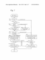
US 20110310285A1
(19) United States
(12) Patent Application Publication (10) Pub. N0.: US 2011/0310285 A1
(43) Pub. Date:
NAKAI
(54)
IMAGING APPARATUS
(52)
(75) Inventor:
YASUNORI NAKAI, Nara (JP)
(73) Assignee:
PANASONIC CORPORATION,
(21) App1.No.:
(22)
Flled:
13/161,590
imaging unit and to be capable of taking a reference position
,
,
,
,
second display unit con?gured to display the image data
_
(JP) ............................... .. 2010 138854
_
_
_
Int. Cl.
H04N 5/222
generated by the imaging unit, and a controller con?gured to
perform control, When the position sensor senses that the ?rst
display unit is not at the reference position, to activate the
proximity sensor, and to operate the ?rst display unit When the
Pubhcatlon Classl?catlon
(51)
An imaging apparatus includes an imaging unit con?gured to
capture a subject image to generate image data, a ?rst display
and a position different from the reference position, a prox
imity sensor con?gured to sense proximity of an object to the
?rst display unit, a position sensor con?gured to sense
Whether the ?rst display unit is at the reference position, a
Forelgn Apphcatlon Prmnty Data
_
ABSTRACT
unit con?gured to display the image data generated by the
Jun‘ 16’ 2011
Jun. 18, 2010
us. c1. .......................... .. 34s/333.06; 348/E05.024
Osaka (JP)
,
(30)
(57)
Dec. 22, 2011
proximity sensor senses proximity of an object, and to operate
the second display unit When the proximity sensor does not
sense proximity of an object.
(2006.01)
356
340
,/
31 0
/
25 i
/ 252
/
230
Patent Application Publication
Dec. 22, 2011 Sheet 1 0f 7
EN
Q2\ .\
L D
CC
KOCZE
8w8m
SN2m/
Emosgz
wA.-
US 2011/0310285 A1
/ .l ?I0%Egmzvo
h
05
2'>
gm
+0653\i
\€\\\
EoHz=9m2zo.
\
\
_
/
\
_
/
\
LUBE_E
/“Uzi/EO
.3
F
\QE9a:ANE
Patent Application Publication
Dec. 22, 2011 Sheet 2 0f 7
US 2011/0310285 A1
251/
250
350
/
340
Fig.
3\0_
230
Patent Application Publication
Dec. 22, 2011 Sheet 3 0f 7
US 2011/0310285 A1
Fig. 3A
SETTING MENU
0
CLOCK
v.
C‘?
EXTERNAL MICROPHONE: OFF
BEEP SOUND ;
OFF
MY
IE
SELECT <3
DETERMINE %
Fig. 3B
SETTING MENU
CLCCK
'‘
EXTERNAL MICROPHONE :
OFF
Ci
BEEP SOUND -.
QFF
5: AUTOMATIC DISPLAY
El
MONITOR SWITCHING :
SELEGTQ»
K20
T’
ON
DETERMINE %
Patent Application Publication
Dec. 22, 2011 Sheet 4 0f 7
US 2011/0310285 A1
300
320
\Z
330
MONITOR 4 -------------- H
200
\
j
l
I
l
J
\\
340
330
Patent Application Publication
Dec. 22, 2011 Sheet 5 0f 7
US 2011/0310285 A1
Fi. 5
/'
CONNECTION OF
EXTERNAL VIEWFINDER
'
S301
IS THERE
EYE PROXIMITY
SENSOR’?
YES
,.
-
I
- SETTING ITEM OF “AUTOMATIC DISELAY MONITOR
$302
SWITCHING" IS ADDED TC SETTING MENU
SETTING ITEM OF “AUTOMATIC DISPLAY MONITOR
SWITCHING” IS SET “CN” BY DEFAULT
-AUTOMATIC SWITCHING FLAG IS SET
S303
MANUAL DISPLAY MONITOR SWITCHING
FUNCTION IS ASSIGNED TO
PREDETERMINED FUNCTION BUTTON“
Patent Application Publication
Dec. 22, 2011 Sheet 6 0f 7
O>F<|§EMwD5 E02O5Z.
US 2011/0310285 A1
.ZOOi“.Hmwmm
Patent Application Publication
Dec. 22, 2011 Sheet 7 0f 7
US 2011/0310285 A1
Fig. 7
( DISPLAY
SWITCHING
OF )
MONITOR
J'AUTOMATIC SW. "
"MANUAL SW."
CURRENT
DISPLAY
MONITOR?
5402
" EXTERNAL VIEWFINDER "
REAR MONITOR
$403
8404
v
DISPLAY MONITOR
DISPLAY MONITOR
FLAG : ON
FLAG = OFF
'4
S405
I
"VARI-ANOLE STATE"
CHECK STATE
OF EXTERNAL
VIEWFINDE
S406
8409
“CLOSED STATE"
v
AUTOMATIC DISPLAY MONITOR
AUTOMATIC DISPLAY MONITOR
SWITCHING FUNCTION : ACTIVE
SWITCHING FUNCTION ; INAOTIvE
(EYE PROXIMITY SENSING
(EYE PROXIMITY SENSING
OPERATION FLAG = ON)
OPERATION FLAG I OFF)
i
S407
"EXTERNAL VIEWFINDER"
CHECK USER
SETTING
"'REAR MONITO R’I
8408 DISPLAY IMAOE DATA ‘
ON REAR MONITOR
‘
NO
S41. 1
S410 m E}
nap!
SENSED7>
PROXIMITY
YES
DISPLAY IMAGE DATA
ON EXTERNAL VIEWFINDER
US 2011/0310285 A1
IMAGING APPARATUS
BACKGROUND
[0001] 1. Technical Field
[0002] The technical ?eld relates to an imaging apparatus
having a plurality of display units including a movable dis
play unit.
[0003] 2. RelatedArt
[0004] JP10-004509A discloses an imaging apparatus
including tWo types of display units, a vieW?nder and a moni
tor. The imaging apparatus includes an eye proximity sensor.
When the proximity of the user’s eye to the vieW?nder is
sensed by the eye proximity sensor, the monitor display is
turned off. When the eye proximity is not sensed, the vieW
?nder display is turned off. By this control, an imaging appa
ratus Which is easy to operate and capable of reducing Wasted
poWer consumption is implemented.
[0005]
In the imaging apparatus disclosed in the above
described JP10-004509A, When the display sWitching
Dec. 22, 2011
the ?rst display unit; and a controller con?gured to control the
?rst and second display units. In a case Where the position
determining unit determines that the ?rst display unit is not
positioned at the reference position, the controller performs
control to operate the ?rst display unit When the proximity
determining unit determines that the object is in proximity to
the ?rst display unit, and to operate the second display unit
When the proximity determining unit does not determine that
the object is in proximity to the ?rst display unit.
[0009] According to the imaging apparatus of the above
aspect, When the ?rst display unit (e.g., an external vieW
?nder) is moved from the reference position, the proximity
sensor is forcibly activated, and When the proximity sensor
senses the proximity of an object, the ?rst display unit is
operated. By this, for example, even if the automatic sWitch
ing function of the display unit is set to invalid, When the user
rotates the ?rst display unit (e.g., an external vieW?nder) to
use the ?rst display unit (the external vieW?nder), the auto
matic sWitching function of the display unit becomes valid.
betWeen the vieW?nder and the monitor is set to “manual
Hence, the setting for changing the display unit Which is
performed due to a change in user’s shooting style is facili
sWitching” instead of “automatic sWitching” Which is per
tated, improving the usability of the imaging apparatus.
formed based on the detection result of the eye proximity
sensor, and the setting is performed to turn off the vieW?nder
display (turn on the monitor display), even if the user looks
through the vieW?nder, nothing is displayed on the vieW
?nder. In such circumstances, When the user Wants to check a
subject by looking through the vieW?nder, he/ she needs to
take the trouble to perform an operation to turn on the vieW
?nder display. Thus, the operation becomes troublesome,
causing a problem of poor usability.
BRIEF DESCRIPTION OF DRAWINGS
[0010]
FIG. 1 is a block diagram shoWing an electrical
con?guration of a camera system.
[0011] FIG. 2 is a rear vieW of the camera system.
[0012] FIG. 3A is a diagram for describing a setting menu
and FIG. 3B is a diagram for describing a setting menu having
the “automatic display monitor sWitching” item added
thereto.
SUMMARY
[0013] FIG. 4A is a diagram for describing a closed state of
an external vieW?nder and FIG. 4B is a diagram for describ
[0006] An imaging apparatus capable of solving the above
described problem is provided that has improved usability of
sWitching betWeen a plurality of display units.
ing a van-angle state of the external vieW?nder.
[0014] FIG. 5 is a ?owchart for describing an operation
performed When the external vieW?nder is connected to a
[0007]
camera body of the camera system according to a ?rst
embodiment.
[0015] FIG. 6 is a diagram shoWing an example of a mes
sage displayed When the external vieW?nder is mounted on
the camera body.
[0016] FIG. 7 is a ?owchart for describing a display moni
tor sWitching operation of the camera system according to the
?rst embodiment.
In a ?rst aspect, an imaging apparatus includes: an
imaging unit con?gured to capture a subject image to gener
ate image data; a ?rst display unit con?gured to display the
image data generated by the imaging unit and to be capable of
being positioned at a reference position and a position differ
ent from the reference position; a proximity sensor con?g
ured to sense proximity of an object to the ?rst display unit; a
position sensor con?gured to sense Whether the ?rst display
unit is positioned at the reference position; a second display
unit con?gured to display the image data generated by the
imaging unit; and a controller con?gured to perform control
such that, When the position sensor senses that the ?rst display
unit is not positioned at the reference position, the controller
activates the proximity sensor, and operates the ?rst display
unit When the proximity sensor senses the object is proximate
to the ?rst display unit, and operates the second display unit
When the proximity sensor does not sense the object is proxi
mate to the ?rst display unit.
[0008]
In a second aspect, an imaging apparatus to Which a
?rst display unit is mountable is provided. The ?rst display
unit is a display unit con?gured to display captured image
data and capable of being positioned at a reference position
and a position different from the reference position. The
imaging apparatus includes: a second display unit con?gured
to display captured image data; a position determining unit
con?gured to determine Whether the ?rst display unit is posi
tioned at the reference position; a proximity determining unit
con?gured to determine Whether the object is in proximity to
DETAILED DESCRIPTION OF PREFERRED
EMBODIMENTS
1. First Embodiment
1-1 . OvervieW
[0017]
A camera system according to the present embodi
ment includes an interchangeable lens and a camera body. An
external vieW?nder is mountable on the camera system
through a connector. The camera body includes a rear liquid
crystal monitor (hereinafter, referred to as a “rear monitor”)
and a connector for connecting the external vieW?nder (here
inafter, referred to as a “connector”). The external vieW?nder
includes an eye proximity sensor, a liquid crystal display unit
(hereinafter, referred to as a “?nder monitor”), and a detection
sWitch that detects a state of the external vieW?nder.
[0018] The folloWing embodiment describes a camera sys
tem to Which an external vieW?nder is mounted, that is, a
camera system including tWo display monitors (a rear moni
US 2011/0310285 A1
Dec. 22, 2011
tor and an external view?nder), which further facilitates the
[0029]
setting performed due to a change in user’s shooting style,
played on the rear monitor 230 and a user can set various
thereby providing excellent usability.
functions of the camera system 1 on the setting menu. The
[0019] An embodiment in which the idea of the present
application is applied to a lens-interchangeable camera sys
tem will be described below using the drawings.
setting menu has, for example, an item of “automatic display
monitor switching” which is a setting for automatically
In the camera system 1, a setting menu can be dis
switching a display monitor based on the sensing result of an
eye proximity sensor 310 (see FIG. 3B).
1-2. Con?guration
[0030]
When the “automatic display monitor switching”
setting is turned on by the user on the setting menu, that is,
[0020]
FIG. 1 is a block diagram showing a con?guration of
a camera system 1 according to a ?rst embodiment. FIG. 2 is
a schematic diagram showing a rear view of the camera sys
automatic switching is set, the microcomputer 220 sets the
automatic switching ?ag 241 to “ON”. When the “automatic
tem 1 according to the ?rst embodiment. The camera system
1 includes an interchangeable lens 100, a camera body 200,
and an external view?nder 300. The interchangeable lens 100
has a Zoom lens and a focus lens (not shown) and guides light
display monitor switching” setting is turned off by the user,
that is, manual switching is set, the microcomputer 220 sets
the automatic switching ?ag 241 to “OFF”. As such, the
automatic switching ?ag 241 indicates the contents of the
setting for automatic display monitor switching, which is set
passing through the interchangeable lens 100 to the camera
by the user on the setting menu.
body 200.
[0021] The camera body 200 includes a CCD image sensor
210, a microcomputer 220, a rear monitor 230, a DRAM 240,
an operating member 250, a card slot 260, and a connector
270.
[0022] In the camera system 1, the CCD image sensor 210
captures a subject image incident through the interchangeable
lens 100, and converts the subject image into an electrical
signal to generate image data. The microcomputer 220 per
forms various image processing and compression processes
on the generated image data and stores the processed image
data in a memory card 400 . A detail of each component will be
described below.
[0023]
The microcomputer 220 controls the overall opera
tion of the camera system 1 according to an instruction from
the operating member 250. For example, the microcomputer
[0031] When the eye proximity sensing operation ?ag 242
is ON, the microcomputer 220 activates the eye proximity
sensor 310. At this time, the microcomputer 220 performs
switching of a display monitor to be operated based on the
sensing result of the eye proximity sensor 310. When the eye
proximity sensing operation ?ag 242 is OFF, the microcom
puter 220 stops or inactivates the operation of the eye prox
imity sensor 310. At this time, the microcomputer 220 deter
mines a display monitor to be operated (a display monitor for
displaying an image), based on the value of the display moni
tor ?ag 243.
[0032] The display monitor ?ag 243 takes the value “ON”
when the display monitor to be operated is the rear monitor
230, and takes the value “OFF” when the display monitor to
be operated is an external view?nder 300 (that is, a ?nder
220 performs various image processing including gamma
monitor 320). The microcomputer 220 sets the eye proximity
sensing operation ?ag 242 based on the connection state of
correction, ?aw correction, white balance correction and the
like, and compression processes including a JPEG compres
the external view?nder 300, the state of the automatic switch
ing ?ag 241, and the state of a detection switch 340. The
sion process, an MPEG compression process and the like, on
the image data obtained from the CCD image sensor 210. The
setting of the eye proximity sensing operation ?ag 242 will be
memory during control operation and image processing.
described in detail later.
[0033] The rear monitor 230 is provided at the rear of the
camera body 200. The ?nder monitor 320 is provided in the
[0024] The DRAM 240 stores at least the following three
?ags 241, 242, and 243 which are used for control.
tured by the CCD image sensor 210, by looking at the ?nder
microcomputer 220 uses the DRAM 240 as a working
external view?nder 300. The user can check an image cap
[0025] Automatic switching ?ag 241: a ?ag indicating
user’s setting state for “automatic display monitor switching”
monitor 320 inside the external view?nder 300. The rear
[0026] Eye proximity sensing operation ?ag 242: a ?ag that
represented by image data subjected to various image pro
monitor 230 and the ?nder monitor 320 display an image
is referred by the microcomputer 220 to determine whether to
cessing, and the like, by the microcomputer 220. The rear
actually perform an eye proximity sensing operation
monitor 230 and the ?nder monitor 320 can display through
[0027] Display monitor ?ag 243: a ?ag indicating a display
monitor to be operated (to function) when the eye proximity
sensing operation ?ag 242 is OFF (that is, when automatic
switching of the display monitor is not performed)
[0028] The value (ON and OFF) of each ?ag and the mean
ings indicated by each value are as follows:
images and still images represented by image data recorded in
the memory card 400. The through image is a moving image
which is displayed to allow a user to determine a composition
upon still image shooting, but is not yet recorded.
[0034] The rear monitor 23 0 and the ?nder monitor 320 can
display a setting menu. For example, the rear monitor 23 0 and
the ?nder monitor 320 can display, as setting menus, a menu
screen for setting the number of pixels of data on an image to
be shot, a menu screen for setting exposure, a menu screen for
Automatic switching
ON
OFF
setting 150 sensitivity, and the like In particular, in the present
Automatic switching
Manual switching
embodiment, when the external view?nder 300 is connected
Eye proximity sensor:
Active
Eye proximity sensor:
Inactive
Rear monitor
External view?nder
flag
Eye proximity
sensing operation
flag
Display monitor flag
to the camera body 200, the rear monitor 230 and the ?nder
monitor 320 can display a setting menu including the afore
mentioned “automatic display monitor switching” setting
item (see FIG. 3B).
[0035]
The operating member 250 is a collective term for
various operating members. Examples of the operating mem
US 2011/0310285 A1
Dec. 22, 2011
ber 250 include a function button 251 and a cross key 252
VieW?nder 300 is rotated upWard With the hinge 330 being a
Which Will be described later. The operating member 250 may
include a touch panel.
[0036] The memory card 400 can be placed in the card slot
260. The memory card 400 can store image data generated by
rotating shaft from the closed state as shoWn in FIG. 4B. Note
the microcomputer 220. The memory card 400 can also out
put the stored data to the microcomputer 220.
[0037] The connector 270 is a connecting device that elec
trically connects the external VieW?nder 300 to the camera
body 200. The microcomputer 220 communicates data such
as external VieW?nder mount information, image data, infor
mation as to Whether there is an eye proximity sensor, and
information on an eye proximity sensing state, With the exter
nal VieW?nder 300 through the connector 270. The external
VieW?nder mount information is information indicating
Whether the external VieW?nder 300 is connected to the con
nector 270, and is used by the microcomputer 220 to deter
mine Whether the external VieW?nder 300 is connected to the
connector 270. When the external VieW?nder 3 00 includes the
that the position When the external VieW?nder 300 is in the
closed state is a reference position of the external VieW?nder
300.
[0041] The detection sWitch 340 is a sWitch Which detects
Whether the state of the external VieW?nder 300 is the closed
state or the Van-angle state. When the external VieW?nder 3 00
is in the closed state, the detection sWitch 340 is OFF. When
the external VieW?nder 300 is in the Van-angle state, the
detection sWitch 340 is am. When in the closed state, the
?nder monitor 320 is oriented toWard the rear of the camera
body 200. That is, When the external VieW?nder 300 is in the
closed state, the orientation of the ?nder monitor 320 sub
stantially matches the direction of an optical axis L of the
interchangeable lens 100.
[0042] Referring to FIG. 2, the eye proximity sensor 310 is
disposed near the loWer portion of the eye proximity WindoW
350. When the user rotates the external VieW?nder 300
is an eye proximity sensor, information indicating that the
upWard about the hinge 330, the eye proximity sensor 310
rotates upWard together With the eye proximity WindoW 350
external VieW?nder 300 includes an eye proximity sensor is
sent to the microcomputer 220 from the external VieW?nder
monitor 320 through the eye proximity WindoW 350, a part of
300 through the connector 270. In the present embodiment,
the face covers the eye proximity sensor 310, and thus the eye
proximity sensor 310 senses that there is an object Within the
eye proximity sensor 310, as information as to Whether there
and the ?nder monitor 320. When the user looks at the ?nder
the external VieW?nder 300 includes the eye proximity sensor
310, but When the external VieW?nder 300 does not include
the eye proximity sensor 310, information indicating that an
eye proximity sensor is not included may be sent to the
predetermined distance, and sends a sensing signal to the
microcomputer 220 through the connector 270.
microcomputer 220.
release button. The cross key 252 includes up, doWn, left, and
[0038] The external VieW?nder 300 includes a hinge 330
that can change the orientation of the external VieW?nder 300,
that is, the eye proximity sensor 310 and the ?nder monitor
320; the detection sWitch 340 that detects a rotation state
(position) of the external VieW?nder 300; and an eye proxim
ity WindoW 350 through Which the user looks the ?nder moni
tor 320.
[0039] The eye proximity sensor 310 is disposed at the rear
of the external VieW?nder 300 and near the eye proximity
WindoW 350. The eye proximity sensor 310 senses the prox
imity of an object, that is, Whether there is an object Within a
predetermined distance from the eye proximity sensor 310.
When the eye proximity sensor 310 senses the presence of an
object, the eye proximity sensor 310 sends information indi
cating that it is in an eye proximity sensing state, to the
microcomputer 220 through the connector 270. On the other
hand, When the eye proximity sensor 310 does not sense the
presence of an object, the eye proximity sensor 310 sends
information indicating that it is in an eye proximity non
sensing state, to the microcomputer 220 through the connec
tor 270. When the user looks the ?nder monitor 320 through
the eye proximity WindoW 350, the eye proximity sensor 310
senses that there is an object (e.g., a part of the user’s face)
Within the predetermined distance, and thus, sends informa
tion indicating an eye proximity sensing state to the micro
computer 220.
[0040] The ?nder monitor 320 of the external VieW?nder
300 can change its angle (position) in an Vertical direction,
With the hinge 330 being a rotating shaft. The rotating shaft of
the hinge 330 is parallel to a horiZontal direction of the cam
era body 200. Speci?cally, the external VieW?nder 300 can
take a closed state (reference state) in Which the underside of
the external VieW?nder 300 is parallel to the topside of the
camera body 200 as shoWn in FIG. 4A; and a state (hereinaf
ter, referred to as a “Vari-angle state”) in Which the external
[0043]
The user can shoot a still image by full-pressing a
right buttons and a set button located at the center thereof. The
user can perform, for example, selection on a menu as a GUI
displayed on the rear monitor 230 or the ?nder monitor 320,
by pressing the Various buttons of the cross key 252.
1 -2-1 . Term Correspondence
[0044] The CCD image sensor 210 is an example of an
imaging unit. The ?nder monitor 320 is an example of a ?rst
display unit. The position of the ?nder monitor 320 in the
closed state is an example of a reference position. The eye
proximity sensor 310 is an example of a proximity sensor. The
detection sWitch 340 is an example of a position detector. The
rear monitor 230 is an example of a second display unit. The
microcomputer 220 is an example of a controller. Also, the
microcomputer 220 is an example of a position determining
unit and a proximity determining unit.
1 -3. Operation
[0045] 1-3 -1 . Operation performed When the external VieW
?nder is connected
[0046] FIG. 5 is a ?owchart for describing an operation
performed When the external VieW?nder 300 is connected to
the camera body 200 of the camera system 1 according to the
?rst embodiment.
[0047] When the microcomputer 220 detects that the exter
nal VieW?nder 300 has been connected to the connector 270
of the camera body 200, the microcomputer 220 detects
Whether there is the eye proximity sensor 310 (S301).
[0048] NoW, an example of a method of detecting Whether
there is the eye proximity sensor 310 Will be described. When
the microcomputer 220 in the camera body 200 and a micro
computer (not shoWn) in the external VieW?nder 300 con?rm
that the external VieW?nder 300 has been connected to the
camera body 200 through the connector 270, communication
US 2011/0310285 A1
Dec. 22, 2011
starts between the microcomputers, and the microcomputer
changing the setting of the “automatic display monitor
220 in the camera body 200 determines whether there is the
eye proximity sensor 310. Alternatively, if the external view
?nder 300 has the function of outputting an identi?cation
switch 340 is changed.
switching” item on the menu; or 3) the state of the detection
microcomputer 220 may determine that a view?nder includ
ing an eye proximity sensor has been attached, when receiv
[0054] FIG. 7 is a ?owchart for describing a display moni
tor switching operation of the camera system 1 according to
the present embodiment.
[0055] When the microcomputer 220 senses that the above
signal indicating that an eye proximity sensor is included, the
ing the identi?cation signal from the external view?nder 300.
described setting/state is changed, ?rst, the microcomputer
Alternatively, it may be set on the menu whether the external
view?nder 300 includes the eye proximity sensor 310.
220 determines, based on the automatic switching ?ag 241,
whether the display monitor switching is set to automatic
[0049] If the microcomputer 220 senses the presence of the
eye proximity sensor 310 by the method as described above
switching or manual switching (S401).
(YES at S301), the microcomputer 220 adds the “automatic
display monitor switching” setting item to the setting menu
(S302). Speci?cally, in the present embodiment, normally, as
shown in FIG. 3A, the “automatic display monitor switching”
is, set to “automatic switching” by the user on the menu, then
item is not displayed on the setting menu. When the presence
of the eye proximity sensor 310 is sensed, as shown in FIG.
[0056]
If the automatic switching ?ag 241 is set to ON, that
the microcomputer 220 sets the eye proximity sensing opera
tion ?ag 242 to ON to activate the automatic display monitor
switching function (5409). The microcomputer 220 receives
a sensing result from the eye proximity sensor 310 And
thereby checks an eye proximity sensing state (5410). If the
3B, the “automatic display monitor switching” item 20 is
sensing result of the eye proximity sensor 310 indicates an
added to the setting menu. At the same time, the microcom
eye proximity sensing state (YES at S410), then the micro
puter 220 sets the initial setting of the “automatic display
monitor switching” to ON, that is, sets “automatic switching”
where the display monitors are automatically switched based
computer 220 sets the external view?nder 300 as the display
monitor to be operated, and an image is displayed on the
?nder monitor 320 in the external view?nder 300 (S411). If
the sensing result of the eye proximity sensor 310 indicates an
on the sensing result of the eye proximity sensor 310, and sets
the automatic switching ?ag 241 to ON. Note that at this time
a message indicating that the automatic display monitor
switching setting is set to ON may be displayed on the rear
monitor 230 to notify it to the user (see FIG. 6).
[0050] Then, the microcomputer 220 assigns a manual dis
play monitor switching function to the predetermined func
tion button 251 (S303). The manual display monitor switch
ing function is the function of forcibly switching the display
eye proximity non-sensing state (NO at S410), then the
microcomputer 220 sets the rear monitor 230 as the display
monitor to be operated, and an image is displayed on the rear
monitor 230 (S408).
[0057] On the other hand, if the automatic switching ?ag
241 is set to OFF at step S401, that is, “manual switching”,
then the microcomputer 220 checks whether the currently
functioning display monitor is the rear monitor 230 or the
monitor to the rear monitor 230 or the external view?nder 3 00
external view?nder 300 (S402). If the currently functioning
by a user’s manual operation. Each time the function button
251 is pressed by the user, the microcomputer 220 switches
the display monitor to be operated between the rear monitor
230 and the ?nder monitor 320, and changes the value of the
display monitor ?ag 243 in association with the switched
display monitor. Note that the manual display monitor
switching function may be assigned to any of the buttons
included in the operating member 250, instead of the function
button 251.
[0051] On the other hand, if the microcomputer 220 does
display monitor is the rear monitor 230, then the microcom
puter 220 sets the display monitor ?ag 243 to “ON” (S403). If
the currently functioning display monitor is the external
view?nder 300, then the microcomputer 220 sets the display
monitor ?ag 243 to “OFF” (S404).
[0058]
Then, the microcomputer 220 checks the state of the
external view?nder 300, based on the state of the detection
switch 340 (S405). Speci?cally, when the state of the detec
tion switch 340 is OFF or is changed from ON to OFF, it is
determined that the external view?nder 300 is in the “closed
not sense the presence of the eye proximity sensor 310 (NO at
state”. Thus, in that case, the microcomputer 220 recognizes
S301), the microcomputer 220 assigns the manual display
that the external view?nder 300 is in the closed state and thus
monitor switching function to the function button 251 (S303).
[0052] By the above-described operation, when the exter
nal view?nder 300 is connected to the camera body 200, the
sets the eye proximity sensing operation ?ag 242 to OFF to
inactivate the automatic display monitor switching function
external view?nder 300 can be used in a state in which the
external view?nder 300 and the rear monitor 230 can be
automatically switched. Thereafter, the user can change the
setting as to whether automatic display monitor switching is
performed (the setting of the automatic switching ?ag 241),
on the “automatic display monitor switching” item 20 (see
FIG. 3B) which is added to the menu.
1-3 -2. Display Monitor Switching Operation
[0053]
A display monitor switching operation of the cam
era system 1 of the present embodiment will be described. In
the present embodiment, switching of the display monitor to
be operated is performed when: 1) the connection of the
external view?nder 300 to the camera body 200 is sensed; 2)
the automatic switching ?ag 241 is changed by the user
(S406).
[0059]
Then, the microcomputer 220 checks the user set
ting for the display monitor by referring to the display moni
tor ?ag 243 (S407). Speci?cally, since the eye proximity
sensing operation ?ag 242 is OFF, the microcomputer 220
determines the display monitor to be operated, based on the
display monitor ?ag 243. When the display monitor ?ag 243
is “OFF”, that is, when the external view?nder 300 is set as
the display monitor to be operated, an image is displayed on
the ?nder monitor 320 in the external view?nder 300 by the
microcomputer 220 (S411). On the other hand, when the
display monitor ?ag 243 is “ON”, that is, when the rear
monitor 230 is set as the display monitor to be operated, by the
microcomputer 220, an image is displayed on the rear moni
tor 230 (S408).
[0060] On the other hand, at step S405, when the state of the
detection switch 340 is ON or is changed from OFF to ON, it
US 2011/0310285 A1
is determined that the external vieW?nder 300 is in the “van
angle state”. Thus, in that case, the microcomputer 220 rec
ogniZes that the external vieW?nder 300 is in the van-angle
state and thus sets the eye proximity sensing operation ?ag
242 to ON to activate the automatic display monitor sWitch
ing function (S409). Thereafter, in the same manner as above,
switching of the display monitor to be operated is performed
Dec. 22, 2011
(tilt-operable) upWard relative to the camera body 200, the
external vieW?nder 300 does not need to be a separate unit
from the camera body 200 and may be formed integrally With
the camera body 200.
[0066]
Though description is omitted in the above-de
scribed embodiment, When the external vieW?nder 300 is
removed from the camera body 200, the microcomputer 220
according to the ?ags and the result of an eye proximity
determines the rear monitor 230 as the display monitor to be
sensing operation.
operated.
[0067]
Although in the above-described embodiment the
1-4. Summary
rear monitor 230 is ?xedly mounted to the rear of the camera
[0061] As described above, a camera system 1 of the
present embodiment includes a CCD image sensor 210 that
body 200, the rear monitor 230 does not necessarily need to
be ?xedly mounted to the rear. For example, a rotating shaft
may be provided on a side surface of the camera body and the
captures a subject image to generate image data; an external
vieW?nder 300 that displays the image data generated by the
CCD image sensor 210 and that can take a reference position
rear monitor 230 may be provided on the camera body 200 so
as to be rotatable about the rotating shaft.
[0068] In the above-described embodiment, the eye prox
imity sensor 310 is disposed adjacent to the eye proximity
(closed state) and a position different from the reference
position (vari-angle state); an eye proximity sensor 310 that
WindoW 350, and When the user rotates the external vieW
senses the proximity of an object to the external vieW?nder
300; a detection sWitch 340 that senses Whether the external
vieW?nder 300 is at the reference position; a rear monitor 23 0
?nder 300, the eye proximity sensor 310 rotates together With
the eye proximity WindoW 350 and the ?nder monitor 320.
HoWever, the eye proximity sensor 310 may be provided on a
that displays the image data generated by the COD image
member on the side of the camera body 200 With respect to the
sensor 210; and a microcomputer 220 that performs control to
activate the eye proximity sensor 310 When the detection
hinge 330.
sWitch. 340 senses that the external vieW?nder 300 is not at
external vieW?nder 300 is connected to the camera body 200,
the reference position, and performs control to operate the
external vieW?nder 300 When the eye proximity sensor 310
senses the proximity of an object, and to operate the rear
monitor 230 When the eye proximity sensor 310 does not
sense the proximity of an object.
[0062] By the above-described con?guration, even if the
display monitor sWitching setting is set to “manual sWitch
ing”, When the user rotates the external vieW?nder 300
upWard to place the external vieW?nder 300 in a van-angle
state, the automatic display monitor sWitching function is
activated. By this, even if the automatic display monitor
[0069]
In the above-described embodiment, When the
the “automatic display monitor sWitching” setting item is
added to the setting menu (step S302 in the ?owchart of FIG.
9. The setting menu may alWays have the “automatic display
monitor sWitching” setting item. In this case, When the exter
nal vieW?nder 300 is not connected to the camera body 200,
the “automatic display monitor sWitching” setting is made
inoperable, and When the external vieW?nder 300 is con
nected to the camera body 200 and the presence of the eye
proximity sensor 310 has been con?rmed, the “automatic
display monitor sWitching” setting is made operable.
[0070] Although, in the above-described embodiment, the
sWitching function is set to invalid, When the user rotates the
external vieW?nder 300 to use the external vieW?nder 300,
COD image sensor 210 is used as an imaging device, the
the automatic display monitor sWitching function becomes
the CCD image sensor 210, other imaging devices such as a
CMOS image sensor and an NMOS image sensor may be
used.
valid. Hence, When the user brings his/her eye in proximity to
the external vieW?nder 300, an image is displayed on the
?nder monitor 320 in the external vieW?nder 300, enabling
the user to, for example, check the image through the external
vieW?nder 300. Accordingly, even if the user changes the
imaging device is not limited thereto. For example, instead of
INDUSTRIAL APPLICABILITY
change the display monitor setting and thus the usability of
[0071] The above embodiments further facilitate the setting
performed due to a change in user’s shooting style and thus
can improve usability. Therefore, the above embodiments can
also be applied to imaging apparatuses such as digital still
the camera system 1 improves.
cameras and digital video cameras.
shooting style from shooting performed While looking at the
rear monitor 230 to shooting performed While looking at the
external vieW?nder 300, he/ she does not need to manually
2. Other Embodiments
[0063] An embodiment is not limited to that described
above and various other embodiments are considered. Other
embodiments Will be summariZed beloW.
[0064] In the above-described embodiment, the camera
system 1 includes the camera body 200 and the interchange
able lens 100 attachable to the camera body 200. HoWever, the
camera body 200 and the lens 100 do not necessarily need to
be separable and the lens 100 and the camera body 200 may
be formed integrally.
[0065] In the above-described embodiment, the external
vieW?nder 300 is detachable from the camera body 200.
HoWever, provided that the ?nder monitor 320 is rotatable
What is claimed is:
1. An imaging apparatus comprising:
an imaging unit con?gured to capture a subject image to
generate image data;
a ?rst display unit con?gured to display the image data
generated by the imaging unit, the ?rst display unit
capable of being positioned at a reference position and a
position different from the reference position;
a proximity sensor con?gured to sense a proximity of an
object to the ?rst display unit;
a position sensor con?gured to sense Whether the ?rst
display unit is positioned at the reference position;
a second display unit con?gured to display the image data
generated by the imaging unit; and
US 2011/0310285 A1
a controller con?gured to perform control such that, When
the position sensor senses that the ?rst display unit is not
Dec. 22, 2011
a controller con?gured to control the ?rst and second dis
play units, Wherein
positioned at the reference position, the controller acti
vates the proximity sensor and operates the ?rst display
in a case Where the position determining unit determines
that the ?rst display unit is not positioned at the reference
unit When the proximity sensor senses the object is
position, the controller performs control to operate the
?rst display unit When the proximity determining unit
determines that the object is in proximity to the ?rst
display unit, and to operate the second display unit When
the proximity determining unit does not determine that
the object is in proximity to the ?rst display unit.
7. The imaging apparatus according to claim 6, Wherein
When the ?rst display unit is attached to a body of the imaging
proximate to the ?rst display unit, and operates the sec
ond display unit When the proximity sensor does not
sense the object is proximate to the ?rst display unit.
2. The imaging apparatus according to claim 1, Wherein the
?rst display unit is mountable to a body of the imaging appa
ratus.
3. The imaging apparatus according to claim 2, Wherein
When the ?rst display unit is mounted to the body of the
imaging apparatus, a setting item for an automatic sWitching
betWeen the ?rst display unit and the second display unit is
added to a menu for alloWing a user to set a function of the
imaging apparatus.
4. The imaging apparatus according to claim 2, further
comprising an operating member used by a user to provide an
instruction to the imaging apparatus, Wherein
When the ?rst display unit is mounted to the body of the
imaging apparatus, the controller assigns a function con
cerning manual sWitching betWeen the ?rst display unit
and the second display unit to the operating member.
5. The imaging apparatus according to claim 1, Wherein
When the position sensor senses that the ?rst display unit is
positioned at the reference position, the controller performs
control to inactivate a function of the proximity sensor.
6. An imaging apparatus to Which a ?rst display unit is
mountable, the ?rst display unit con?gured to display cap
tured image data and capable of being positioned at a refer
ence position and a position different from the reference
position, the imaging apparatus comprising:
a second display unit con?gured to display captured image
data;
a position determining unit con?gured to determine
Whether the ?rst display unit is positioned at the refer
ence position;
a proximity determining unit con?gured to determine
Whether an object is in proximity to the ?rst display unit;
and
apparatus, the controller adds a setting item for automatic
sWitching betWeen the ?rst display unit and the second dis
play unit to a menu for alloWing a user to set a function of the
imaging apparatus.
8. The imaging apparatus according to claim 6, further
comprising an operating member for providing an instruction
to the imaging apparatus by a user, Wherein
When the ?rst display unit is attached to a body of the
imaging apparatus, the controller as signs a function con
cerning manual sWitching betWeen the ?rst display unit
and the second display unit to the operating member.
9. An imaging apparatus comprising:
a ?rst display unit con?gured to be positioned at a reference
position and a position different from the reference posi
tion, the ?rst display unit operable to output a display;
a proximity sensor con?gured to sense a proximity of an
object to the ?rst display unit, the proximity sensor
operable to be activated When the ?rst display unit is
positioned at the position different from the reference
position;
a second display unit con?gured to output a display; and
a controller con?gured to control operation of the ?rst
display unit and the second display unit;
Wherein, When the ?rst display unit is not positioned at the
reference position, the controller operates the ?rst dis
play unit When the proximity sensor senses the object is
proximate to the ?rst display unit, and operates the sec
ond display unit When the proximity sensor does not
sense the object is proximate to the ?rst display unit.
*
*
*
*
*


![TR4W User Manual [English Version]](http://vs1.manualzilla.com/store/data/005728234_1-e27c4fea1c6d513d6e0fdc1451ef66f1-150x150.png)