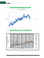
1
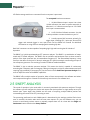
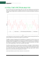
BB60C Spectrum Analyzer User Manual Signal Hound BB60C User Manual 2015, Signal Hound th 35707 NE 86 Ave La Center, WA Phone 360.263.5006 • Fax 360.263.5007 ii Contents 1 Overview............................................................................................................................................................................. 5 1.1 What’s New .......................................................................................................................................................................... 5 2 Preparation ........................................................................................................................................................................ 5 2.1 Initial Inspection.................................................................................................................................................................. 5 2.2 Software Installation .......................................................................................................................................................... 6 2.2.1 Software Requirements .............................................................................................................................................. 6 2.3 Connecting Your Signal Hound........................................................................................................................................ 6 2.4 The BB60 Front and Rear Panels .................................................................................................................................... 6 3 Modes of Operation .......................................................................................................................................................... 7 3.1 Swept Analysis .................................................................................................................................................................... 7 3.2 Real-Time Spectrum Analysis .......................................................................................................................................... 8 3.3 Zero-Span Analysis ............................................................................................................................................................ 9 3.3.1 Triggering in Zero Span .............................................................................................................................................. 9 4 Understanding the BB60C Hardware ........................................................................................................................... 10 4.1 Front End Architecture ....................................................................................................................................................10 4.2 Description .........................................................................................................................................................................10 4.3 Residual Signals ............................................................................................................................................................... 11 4.4 Scalloping Loss ................................................................................................................................................................. 11 4.5 Dynamic Range ................................................................................................................................................................. 12 5 Troubleshooting .............................................................................................................................................................. 12 5.1 Unable to Find or Open the Device ................................................................................................................................ 12 5.1.1 The Device Light is Green and Still Won’t Connect ............................................................................................. 12 5.1.2 A Power Cycle Does Not Fix the Problem ............................................................................................................. 12 5.2 The Device is Not Valid .................................................................................................................................................... 12 6 Calibration and Adjustment ........................................................................................................................................... 12 7 BB60C Specifications ..................................................................................................................................................... 13 8 Warranty and Disclaimer................................................................................................................................................ 14 8.1 Warranty ............................................................................................................................................................................. 15 8.2 Warranty Service .............................................................................................................................................................. 15 8.3 Limitation of Warranty ..................................................................................................................................................... 15 8.4 Exclusive Remedies ......................................................................................................................................................... 15 8.5 Certification ....................................................................................................................................................................... 15 8.6 Credit Notice ...................................................................................................................................................................... 15 9 Appendix .......................................................................................................................................................................... 16 iii 9.1 Typical Performance Characteristics of the BB60C .................................................................................................. 16 9.1.1 Third Order Intercept (TOI) ....................................................................................................................................... 16 9.1.2 Typical Amplitude Accuracy .................................................................................................................................... 16 9.1.3 Typical Displayed Average Noise Level ................................................................................................................. 17 9.1.4 Typical Performance over Temperature ............................................................................................................... 17 iv Overview | What’s New 1 Overview This document outlines the operation and functionality of the BB60C Signal Hound spectrum analyzer. This document will help you understand the capabilities, performance specifications, and features of your BB60C. 1.1 WHAT’S NEW Version 3.0.0: With the release of the Spike software, a single software platform now servers all Signal Hound spectrum analyzers. The description of how to use the software with the BB60C is now found in the Spike software manual. 2 Preparation The BB60C is a real-time high speed spectrum analyzer communicating with your PC over a USB 3.0 Super Speed link. It has 27 MHz of real-time bandwidth, tunes from 9 kHz to 6 GHz, collects 80 million samples per second, and streams data to your computer at 140 MB/sec. By adding a high speed hard drive to your PC or laptop (250 MB/s sustained write speed), the BB60C doubles as an RF recorder, streaming up to 80 million IF samples per second, or 40 million I/Q samples to disk. 2.1 INITIAL INSPECTION Check your package for shipping damage before opening. Your box should contain a USB 3.0 Ycable, a CD-ROM, and a Signal Hound BB60C. 5 Preparation | Software Installation 2.2 SOFTWARE INSTALLATION See the Spike Software manual for installation instructions. You must have administrator privileges to install the software. During installation, the BB60 device drivers will also be installed. It is recommended to install the application folder in the default location. 2.2.1 Software Requirements Supported Operating Systems • • Windows 7 (64-bit) Windows 8 (64-bit) Minimum System Requirements • • • Processor – Intel Desktop quad-core i-Series processors*** 8 GB RAM – 1 GB for the BB60 software Native USB 3.0 support Recommended System Requirements • • • • • Windows 7 64-bit Processor – Intel Desktop quad-core i5 / i7 processors 8 GB RAM - 1 GB for the BB60 software Native USB 3.0 support OpenGL 3.0 capable graphics processor** (** Certain display features are accelerated with this functionality, but it is not required.) (*** Our software is highly optimized for Intel CPUs. We recommend them exclusively.) 2.3 CONNECTING YOUR SIGNAL HOUND With the software and BB60 drivers installed, you are ready to connect your device. Plug in both the male USB 3.0 and male USB 2.0 connections into your PCs respective USB ports, and then plug the USB 3.0 Micro-B male connection into the BB60 device. Your PC may take a few seconds recognizing the device and installing any last drivers. Wait for this process to complete before launching the Spike software. 2.4 THE BB60 FRONT AND REAR PANELS The front panel includes a 50Ω SMA RF Input. Do not exceed +20 dBm or damage may occur. A READY/BUSY 6 Preparation | Swept Analysis LED flashes orange each time a command from the computer is processed. The rear panel has three connectors: 1. 10 MHz Reference input / output. Use a clean 10 MHz reference sine wave or square wave with >0 dBm level. A +13 dBm sine wave input or 3.3V CMOS clock input is recommended. 2. A USB 3.0 Micro-B female connector. Use the Y-cable provided to connect the device to your PC. 3. A multi-purpose BNC connector, primarily for trigger input, including GPS 1 pulse per second (PPS) trigger and external trigger in zero span mode. See the BB60C API manual for additional information on using GPS time stamping with streaming I/Q data Both BNC connectors are also capable of outputting logic high and low using the API. Modes of Operation The BB60C is a hybrid superheterodyne-FFT spectrum analyzer. The BB60C is a combination of swepttuned and FFT based analyzers. The BB60C uses an oscillator and band-pass filters to down-convert a portion of the input spectrum into an intermediate frequency (IF). The intermediate frequency is then sent from the device to the host PC where it undergoes FFT spectrum analysis transforming the input IF into a frequency spectrum. The resulting IF contains 27MHz of usable bandwidth. The BB60C is also a real-time spectrum analyzer. This means the device is capable of continuously streaming the IF frequency with no time gaps. Having no time gaps is critical for measurements and tests requiring high probability of intercept (POI). See the section below Real-Time Spectrum Analysis for a more in-depth discussion of the BB60C capabilities. The BB60C offers multiple modes of operation. Most of these are exposed in the software and others can be exposed through our C-based API. We will only cover those in our software here. 2.5 SWEPT ANALYSIS This mode of operation is the mode which is commonly associated with spectrum analyzers. Through the software you will configure the device and request the device perform a single sweep across your desired span. Spans larger than 20MHz are the result of acquiring multiple 20MHz patches and concatenating the results of the FFT processing on each. The processing performed on each 20MHz patch is determined by the settings provided. Each time a trace is returned, the device waits until the next trace request. For you, the software user, you can choose to continuously retrieve traces or manually request them one at a time with the Single and Continuous buttons found on the Sweep Toolbar. 7 Preparation | Real-Time Spectrum Analysis 2.6 REAL-TIME SPECTRUM ANALYSIS One of the issues with the standard sweep mode is the “blind time” between each trace. Blind time refers to the time between spectrum sampling. During this time, we are processing the last capture, or viewing the data. During this time it is possible to miss an event. The picture below shows a missed event in green. In this image we see an event missed due to the blind time between spectrum sampling. With Real-Time spectrum analysis we can prevent this and capture ALL possible events. The BB60C is capable of streaming the full IF bandwidth with no time gaps. If we limit our spans to the maximum instantaneous bandwidth we can now process every spectrum sample for our resulting trace. The BB60C performs overlapping FFTs at an overlapping rate of 75%, covering each point of data with 4 FFTs. We take the resulting FFTs and min/max or average them into a final returned trace. The number of FFT results merged depends on Real-Time Accumulation and the RBW. The minimum signal duration to guarantee the same amplitude as a CW signal (i.e. 100% probability of intercept) in real-time analysis mode is a function of the resolution bandwidth selected, and is equal to1.25 times the FFT interval. The FFT interval is approximately 2 / RBW, so for a 631 kHz RBW, this works out to about 4 microseconds. Lower RBWs will require proportionally longer signal duration. However, signals of even ¼ this duration will be displayed only 2-3 dB down. See the Spike Software manual for further information on Real-time mode. 8 Preparation | Zero-Span Analysis 2.7 ZERO-SPAN ANALYSIS Zero span analysis allows you to view and analyze signals in the time domain. The BB60 application can display amplitude, frequency, and phase vs. time, and display the results through multiple plots. See the Spike Software manual for further information on using Zero Span analysis. 2.7.1 Triggering in Zero Span You can specify a video trigger, external trigger, or no trigger. Video triggers allow you to begin the sweep only after a signal exceeds the amplitude specified in the Video Trigger input. This is useful when you need to analyze a periodic transmission. If your transmitter has a trigger output, you can route this to the BB60 trigger in. Select “external trigger” to cause the zero-span sweep to begin after this hardware trigger. You can trigger on the rising edge or falling edge of a signal. A 3.3V CMOS trigger with 50 ohm output impedance is ideal, but 5V logic with 50 ohm output impedance is acceptable. Higher or lower output impedance may work with a short BNC cable, but longer cables may cause issues with reflection. If your trigger output is sensitive to loading, start zero span mode with external trigger enabled before connecting your trigger, to ensure the BB60 trigger port is configured as an input. 2.8 SCALAR NETWORK ANALYSIS When paired with a USB-TG44A, or a USB-TG124A, the BB60C may be used as a scalar network analyzer. This may require a firmware update. In the Spike software, verify you have firmware version 5 or higher. If not, check the Signal hound website for an update. See the Spike software manual for more information. 9 Understanding the BB60C Hardware | Front End Architecture 3 Understanding the BB60C Hardware 3.1 FRONT END ARCHITECTURE 3.2 DESCRIPTION The BB60C is a two-stage superheterodyne receiver, using two independent intermediate frequencies (IF), selected based on RF input frequency. Each IF has a corresponding distributed element notch filter in the RF section to reduce spurious responses from input signals at the IF frequency. Each RF band also has a distributed element filter buried in the multilayer PCB laminate, engineered to reject that band’s image frequencies and reduce LO feed-through. Wherever possible, RF band pass filters were used to reject signals which could result in spurious mixer products, such as ½ of the tuned RF frequency, or image frequencies. To reduce spurious signals from second-order intermodulation where filtering was not practical, push-pull amplifiers were used in both the preamplifier and mixer stages, effectively canceling even-order mixing products. Direct conversion was used below 10 MHz, completely avoiding the intermodulation products associated with mixing. 10 Understanding the BB60C Hardware | Residual Signals Gain control is achieved in the BB60C using the front-end attenuator and preamplifier. The front end was designed to provide good spurious-free dynamic range (SFDR) at any reference level, typically better than 50 dB. The 14-bit ADC uses built-in dithering to further improve the linearity and decrease spurious responses at the IF level. Spurs from the ADC are typically 70 dB below the carrier. From the ADC, digitized IF data is handed off to an FPGA where it is packetized. The Cypress FX3 peripheral controller streams the packetized data over a USB 3.0 link to the PC, where 80 million, 14-bit ADC samples per second are processed into a spectrum sweep or I/Q data stream. 3.3 RESIDUAL SIGNALS A residual signal appears even when there is no signal input. The BB60C has some low level residual signals at multiples of 10 MHz, typically not visible unless a narrow span (<10 kHz) is used. These are typically very low (-130 dBm for a reference level of -50 dBm), except for a few frequencies where signals may be as high as -107 dBm for a reference level of -50 dBm. 3.4 SCALLOPING LOSS An FFT-based spectrum analyzer uses digital resolution bandwidths rather than discrete analog filters. Moving from analog to digital introduces some new terms important to measurement accuracy, like FFT bins, window functions, spectral leakage and scalloping loss. To sum up, an FFT produces an array of discrete frequency bins and their associated amplitude. Real-world signals rarely line up exactly with a single frequency bin, which can result in some ugly behavior unless a window function is used. Many different window functions are available, with various strengths and weaknesses. For the BB60C, swept modes default to a flat top window, which offers excellent amplitude flatness and therefore very little scalloping loss, in exchange for a wider resolution bandwidth and longer processing time. Most RBWs used by the BB60C are from flat top windows, so scalloping loss is negligible. In real-time mode, “native” bandwidths from a specific window function are used, which have a narrower bandwidth to reduce processing time and level out impulse response. However, when a signal falls halfway between two “bins,” the energy is split between adjacent bins such that the reported “peak” amplitude may be lower by as much as 0.8 dB. To get an accurate CW reading using “Marker peak”, the non-native bandwidths in swept mode are recommended. In either mode, the “channel power” utility, which integrates the power across any channel bandwidth you specify, also eliminates this scalloping loss, giving you a full accuracy amplitude reading even in realtime mode. 11 Troubleshooting | Dynamic Range 3.5 DYNAMIC RANGE Dynamic range has many definitions, but one common definition in spectrum analysis is 2/3(TOI – DANL). A typical number for 1 GHz would be: TOI=-19 dBm, DANL = -151 dBm (10 Hz RBW). Dynamic range, 2/3 (TOI – DANL) = 88 dB, and would be a function of RBW, frequency, gain and attenuation settings, etc. 4 Troubleshooting If you experience a problem with your Signal Hound, please try these troubleshooting techniques before contacting us. 4.1 UNABLE TO FIND OR OPEN THE DEVICE Ensure the device is plugged in and the green light is on. If it is not, unplug then plug in the device. Once the green light turns on, use the File menu to try to connect the device again. 4.1.1 The Device Light is Green and Still Won’t Connect This is often the case when the device is plugged in when a PC has been turned on. We recommend leaving the device unplugged when you turn off your PC. If this is the case, a power cycle will solve this issue. 4.1.2 A Power Cycle Does Not Fix the Problem If a power cycle still does not allow you to connect the device, it is possible the device drivers were not successfully installed. See the Driver Installation section for information about the BB60 drivers. 4.2 THE DEVICE IS NOT VALID In the event the device ceases to operate or becomes corrupted, the application might tell you the device does not appear to be valid. Before contacting us, attempt to power cycle the device and restart your computer to ensure nothing else is causing this issue. If the issue persists, please contact us. 5 Calibration and Adjustment Calibration software is available for the BB60C at no charge, but requires specialized equipment normally only found in calibration labs. Contact Signal Hound for more information regarding calibration software and required equipment, or to schedule a calibration. 12 BB60C Specifications | The Device is Not Valid 6 BB60C Specifications The following preliminary specifications are based on being in the Preset condition, using internal timebase, video processing set for average and power, plus VBW, sweep, gain, and attenuation in the default auto mode. Frequency range 9 kHz to 6 GHz Streaming Digitized I/Q 250 kHz to 27 MHz of selectable IF bandwidth that is amplitude corrected Resolution Bandwidths (RBW) 10 Hz to 10 MHz Internal Timebase Accuracy ± 1 ppm per year Sweep Speed (RBW ≥10 kHz) 24 GHz/sec Amplitude (RBW ≤100 kHz) Range: +10dBm to Displayed Average Noise Level (DANL) Absolute Accuracy ± 2.0 dB (arbitrary & non-native RBWs) + 2.0 dB/-2.6 dB (native RBW’s – faster DSP) RF Input frequency VSWR at tuned LO Leakage at RF Input Displayed Average Noise Level (DANL)* ≤ 3.0:1 (<10 dB attenuation) ≤ 1.5:1 (≥10 dB attenuation) -80 dBm Input Frequency Range 9 kHz to 500 kHz 500 kHz to 10 MHz 10 MHz to 6 GHz dBm/Hz -140 -154 -158 + 1.1dB/GHz Residual Responses* Ref Level ≤ -50 dBm, 0 dB Attenuation Input Frequency Range Residual Level 500 kHz to 6 GHz -106 dBm Spurious Mixer Responses* -50dBc (any ref level from +10dBm to -50dBm, in 5dB increments, input signal 10 dB below ref level, and ≤30kHz RBW) 13 Warranty and Disclaimer | The Device is Not Valid SSB Phase Noise at 1 GHz Center Frequency* Recommended Computer Offset Frequency 100 Hz 1 kHz 10 kHz 100 kHz 1 MHz dBc/Hz -70 -76 -83 -93 -117 Windows® 7 or 8 operating system, 8 GB of RAM, Intel i7, 3rd generation (Ivy Bridge) or later with a quad core processor, one USB 3.0 port, and one adjacent USB 2.0 or USB 3.0 port. Note: RF recording using streaming I/Q bandwidths > 8 MHz requires the computer’s mass storage drive to have at least 250MB/sec of sustained write speed such as an SSD, RAID-0, or RAID-5. Synchronization (≤ 20 MHz IBW) 1 PPS GPS input port enables ± 50ns time-stamping Operating Temperature 32°F to 149°F (0°C to +65°C) Standard; -40°F to 149°F (-40°C to +65°C) for Option-1 Weight Net, 1.10 lbs. (0.50 kg) Size 8.63” x 3.19” x 1.19” (219mm x 81mm x 30mm) Power (1) USB 3.0 port and (1) adjacent USB 2.0 or USB 3.0 port Control and Communication USB 3.0 serial bus *DANL, Residual Responses, Spurious Mixer Responses, and Phase Noise specifications apply only at 20°C to 25°C. Typical variations, over the analyzer’s operating temperature, from the specifications at 20°C to 25°C are published in Appendix: Typical Performance Characteristics of the BB60C. ** IP2 and IP3 typical performance specifications can be found in the Appendix: Typical Performance Characteristics of the BB60C. 7 Warranty and Disclaimer ©2013-2015 Signal Hound. All rights reserved. Reproduction, adaptation, or translation without prior written permission is prohibited, except as allowed under the copyright laws. 14 Warranty and Disclaimer | Warranty 7.1 WARRANTY The information contained in this manual is subject to change without notice. Test Equipment Plus makes no warranty of any kind with regard to this material, including, but not limited to, the implied warranties or merchantability and fitness for a particular purpose. Signal Hound shall not be liable for errors contained herein or for incidental or consequential damages in connection with the furnishing, performance, or use of this material. This Signal Hound product has a warranty against defects in material and workmanship for a period of one year from date of shipment. During the warranty period, Signal Hound will, at its option, either repair or replace products that prove to be defective. 7.2 WARRANTY SERVICE For warranty service or repair, this product must be returned to Signal Hound. The Buyer shall pay shipping charges to Signal Hound and Signal Hound shall pay UPS Ground, or equivalent, shipping charges to return the product to the Buyer. However, the Buyer shall pay all shipping charges, duties, and taxes, to and from Signal Hound, for products returned from another country. 7.3 LIMITATION OF WARRANTY The foregoing warranty shall not apply to defects resulting from improper use by the Buyer, Buyersupplied software or interfacing, unauthorized modification or misuse, operation outside of the environmental specifications for the product. No other warranty is expressed or implied. Signal Hound specifically disclaims the implied warranties or merchantability and fitness for a particular purpose. 7.4 EXCLUSIVE REMEDIES The remedies provided herein are the Buyer’s sole and exclusive remedies. Test Equipment Plus shall not be liable for any direct, indirect, special, incidental, or consequential damages, whether based on contract, tort, or any other legal theory. 7.5 CERTIFICATION Signal Hound certifies that, at the time of shipment, this product conformed to its published specifications. 7.6 CREDIT NOTICE Windows® is a registered trademark of Microsoft Corporation in the United States and other countries. Intel® and Core™ are trademarks or registered trademarks of the Intel Corp. in the USA and/or other countries. 15 Appendix | Typical Performance Characteristics of the BB60C 8 Appendix 8.1 TYPICAL PERFORMANCE CHARACTERISTICS OF THE BB60C Below are characteristics of the BB60C which have shown to be typical. These are not hard specifications but show the typical performance in a few aspects not covered in our official specs. The official BB60C device specifications can be found in this document under the section titled BB60C Specifications. 8.1.1 Third Order Intercept (TOI) Freq(GHz) 1 2.5 4 5.5 Typical IIP3 at Specified Reference Level (dBm) Gain and Atten = AUTO R.L. = -50 -40 -30 -20 -10 0 -19.2 -10.2 -0.2 9.8 25.7 32* -19.4 -10.4 -0.4 9.6 23.5 32* -14.7 -5.7 4.3 14.3 26.0 32* -18.4 -9.4 0.6 10.6 21.8 31.0 *Typical Performance of internal step attenuator 8.1.2 Typical Amplitude Accuracy 16 10 32* 32* 32* 32* Appendix | Typical Performance Characteristics of the BB60C 8.1.3 Typical Displayed Average Noise Level 8.1.4 Typical Performance over Temperature 8.1.4.1 Spurious Mixer Responses* -50 0 500 1000 1500 2000 2500 3000 -40 C Harmonic Responses (dBc) -30 C -20 C -10 C 0C -60 10 C 21 C 32 C 43 C 54 C -70 Frequency (MHz) 17 65 C Appendix | Typical Performance Characteristics of the BB60C *Signal 10 dB below reference level. To calculate IP2 at a given frequency, subtract this number from signal level (e.g. -30 dBm reference level would be a -40 dBm signal. Subtract e.g. -64dB @ 2 GHz for an IP2 of +24 dBm). 8.1.4.2 Phase Noise Typical Phase Noise Across Temperature at 1 GHz -40 C -60 -65 100 1,000 10,000 100,000 -20 C -70 dBc/Hz -30 C -10 C -75 0C -80 10 C 21 C -85 32 C -90 43 C -95 54 C 65 C -100 Offset (Hz) 8.1.4.3 Displayed Average Noise Level Change over Temperature Typical DANL change (dB) 2 Change from 25 C (dB) 1.5 -60 1 0.5 0 -40 -20 -0.5 0 20 -1 -1.5 -2 Temperature (deg C) 18 40 60 80 Appendix | Typical Performance Characteristics of the BB60C * Shown for gain 3, attenuator 0 dB. For auto gain/attenuator settings at cold temperatures, a reference level of -55 dBm may be required for maximum sensitivity, instead of the usual -50 dBm. 8.1.4.4 Residual Signals over Temperature Temperature typically has little effect on residual signal levels. 19