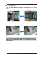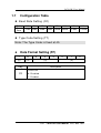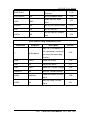
1
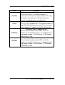
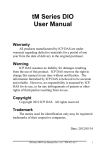
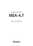
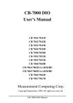
I-87211W User Manual I-87211W User Manual v2.6 High Quality, Industrial Data Acquisition, and Control Products 1/93 I-87211W User Manual V2.6, Oct. 2011 I-87211W User Manual Warranty All products manufactured by ICP DAS are warranted against defective materials for a period of one year from the date of delivery to the original purchaser. Warning ICP DAS assumes no liability for damages consequent to the use of this product. ICP DAS reserves the right to change this manual at any time without notice. The information furnished by ICP DAS is believed to be accurate and reliable. However, no responsibility is assumed by ICP DAS for its use, or for any infringements of patents or other rights of third parties resulting from its use. Copyright Copyright 2011 by ICP DAS CO., LTD. All rights reserved worldwide. Trademark The names used for identification only may be registered trademarks of their respective companies. Version Date Author Description 1.0 2010/2/1 Anold Release version 2/93 I-87211W User Manual V2.6, Oct. 2011 I-87211W User Manual Table of Contents 1 Introduction............................................................................................................5 1.1 Features .........................................................................................................7 1.1 1.2 1.3 1.4 Features .........................................................................................................8 Supports ICP DAS Units ...........................................................................8 Package List .............................................................................................13 Hardware..................................................................................................14 Specifications ...............................................................................................15 Block Diagram for the I-87211W ................................................................17 Pin assignments and LED Indicators ...........................................................18 Operation modes ..........................................................................................19 Wiring Recommendations ...........................................................................21 Wiring ..........................................................................................................21 1.5 Dimensions ..............................................................................................23 2 1.6 Installation................................................................................................24 1.7 Configuration Table .................................................................................25 1.8 Technical Support ....................................................................................26 DCON Protocol....................................................................................................27 2.1 2.2 2.3 2.4 % AANNTTCCFF ...................................................................................31 #**............................................................................................................34 #AA..........................................................................................................36 #AAN.......................................................................................................38 2.5 2.6 #AA00(Data)............................................................................................41 #AA0A(Data)...........................................................................................43 2.7 2.8 #AA1cDD ................................................................................................45 #AAAcDD ...............................................................................................47 2.9 2.10 2.11 2.12 2.13 $AA2........................................................................................................49 $AA4........................................................................................................51 $AA5........................................................................................................53 $AA6........................................................................................................55 $AAC .......................................................................................................57 2.14 2.15 2.16 $AAD.......................................................................................................59 $AAF........................................................................................................61 $AAM ......................................................................................................62 2.17 2.18 2.19 2.20 $AALS .....................................................................................................63 @AA ........................................................................................................65 @AA(Data)..............................................................................................67 ~AAO(Name)...........................................................................................69 3/93 I-87211W User Manual V2.6, Oct. 2011 2.21 2.22 2.23 I-87211W User Manual ~AAD.......................................................................................................71 ~AADVV .................................................................................................73 ~AAI ........................................................................................................75 2.24 2.25 2.26 2.27 ~AATnn ...................................................................................................77 ~** ...........................................................................................................80 ~AA0........................................................................................................81 ~AA1........................................................................................................83 2.28 2.29 2.30 2.31 ~AA2 .......................................................................................................85 ~AA3EVV ..............................................................................................87 ~AA4V ....................................................................................................89 ~AA5V ....................................................................................................91 Appendix1 Dual Watchdog Operation.........................................................................93 4/93 I-87211W User Manual V2.6, Oct. 2011 I-87211W User Manual 1 Introduction The I-87K Series of modules from ICP DAS can support either MCU or I/O expansion units. The I-87211W features high sensitivity and low power, and an ultra small form factor and includes DCON and GPS protocols. The internal GPS module is powered by a MediaTek solution and can provide superior sensitivity and performance, even in as urban canyon environment or an environment with dense foliage environment. Except for the GPS data, I-87211W includes a 2-channel DO and a 1-channel PPS for user applications. The Pulse Per Second (PPS) is an electrical signal that very precisely indicates the start of a second, and can be used for precise timekeeping and time measurement. The PPS functionality can be combined with another time source that provides the full date and time in order to ascertain the time both accurately and precisely. Consequently, the I-87211W can act as a powerful GPS module as well as a general purpose GPS module with an RS-232 interface for use with PACs and remote I/O expansion units. It can also be implemented in automotive navigation system, personal positioning and navigation system, marine navigation and satellite time correction system, etc. 5/93 I-87211W User Manual V2.6, Oct. 2011 I-87211W User Manual Applications: Automotive navigation Personal positioning and navigation Marine navigation Satellite time correction Precise timekeeping and time measurement Transfer Passenger’s Image Administrative Center Passenger 6/93 I-87211W User Manual V2.6, Oct. 2011 I-87211W User Manual Time Calibration for PACs 7/93 I-87211W User Manual V2.6, Oct. 2011 I-87211W User Manual 1.1 Features Supports PACs and Remote I/O expansion units by ICP DAS MediaTek high-sensitivity GPS solution Supports 66-channel GPS and NMEM v0183 v3.01 RS-232 supports NEMA v0183 v3.01 format or the DCON protocol Built-in 2-channel DO, 1-channel PPS (1 pulse per second), 1 RS-232 port PPS: 100 ms pulse output/sec for precise timekeeping and time measurement Various system LED indicators DIN Rail mounting 1.2 Supports ICP DAS Units PAC Units: ICP DAS provides a series of PAC (Programmable Automation Controller) units that are especially suited for industrial control systems in harsh environments. The I-87211W can be inserted into these PACs for applications such as vehicle navigation, Marine navigation and Satellite time correction system, etc. For detailed information regarding PACs, please visit: http://www.icpdas.com/products/Products-list.htm#P1 Item Description Equipped with an AMD LX 800 CPU (500MHz) running the XPAC Windows Embedded Standard 2009 operating system, a vaitety of connectivity types (VGA, USB, Ethernet, RS-232/RS-485) with 3/7 slots for high performance parallel I/O modules (high profile I-8K series) and serial-type I/O modules (high profile I-87K I/O modules). Windows Embedded Standard 2009 8/93 I-87211W User Manual V2.6, Oct. 2011 I-87211W User Manual Equipped an AMD LX 800 CPU (500MHz) running the Windows Embedded Standard 2009 operating system, a vaitety of connectivity types (VGA, USB, Ethernet, RS-232/RS-485) with 3/7 slots for high performance parallel I/O modules (high profile I-8K series) and serial-type I/O modules (high profile I-87K I/O modules). Windows Embedded CE 6.0 XPAC-CE6 WinPAC is equipped with a PXA270 CPU (520MHz) running the Windows CE.NET 5.0 operating system, a vaitety of connectivity WinPAC types (VGA, USB, Ethernet, RS-232/485) with 1/4/8 slots for high performance parallel I/O modules (high profile I-8K series) and serial-type I/O modules (high profile I-87K I/O modules). Windows CE 5.0 LinPAC-8000 gives users all of the best features of both traditional PLCs and Windows capable PCs. The LinPAC-8000 includes a LinPAC VGA port allowing users to choose a regular LCD monitor for the display of HMI application, a USB port to connect with a Keyboard, Mouse, a USB device for storage or touch monitor, and micro SD/microSDHC memory for storage of programs and data. Linux OS 9/93 I-87211W User Manual V2.6, Oct. 2011 I-87211W User Manual ViewPAC is an innovative product developed by ICP DAS. It is a PAC that combines display, operation and control in a single unit. ViewPAC provides the perfect solution to integrating HMI, data acquisition and control in a single PAC. OS: Windows CE 5.0, MiniOS7 ViewPAC The iPAC-8000 is a new family of compact, modular, intelligent and rugged, distributed I/O (input/output) systems, designed for data acquisition and control in manufacturing, research and education. OS: MiniOS7 iPAC 10/93 I-87211W User Manual V2.6, Oct. 2011 I-87211W User Manual Remote I/O Expansion Units ICP DAS provide remote I/O Expansion Units to enable users to extend I/O applications using RS-485, Ethernet or USB interfaces. The I-87211W can also be installed in these units. For more details, please visit: http://www.icpdas.com/products/io_expansion_unit/IO_Expan sion_Unit.htm RS-485 I/O Expansion units USB I/O Expansion units Intelligent Ethernet I/O Expansion units11/93 I-87211W User Manual V2.6, Oct. 2011 I-87211W User Manual Description Item RU-87Pn Intelligent RS-485 I/O expansion unit The RU-87Pn series is a remote intelligent I/O expansion unit that can be used to expand I-87K series I/O modules connected to an RS-485 network for industrial monitoring and control applications. I-87Kn USB-87Pn ET-87Pn RS-485 I/O expansion unit This unit is only equipped with a single power module, a single RS-485 interface and several I/O slots. It can be used to expand I/O modules via the RS-485 interface. Intelligent USB I/O expansion unit This unit can be used to expand I-87K series I/O modules via the RS-485 interface. It is equipped with a single power module, 1 USB interface, 1 CPU module and several I/O slots. Intelligent Ethernet I/O expansion unit This unit can be used to expand I-87K series I/O modules via an Ethernet interface. It is equipped with a single power module, 2 Ethernet ports, 1 CPU module and several I/O slots. 12/93 I-87211W User Manual V2.6, Oct. 2011 I-87211W User Manual 1.3 Package List One I-87211W Module Software Utility CD RS-232 Cable Quick Start Guide Item I-87211W External GPS antenna (ANT-115-03, Length: 5m) RS-232 Cable (CA-0915) Product CD Quick Start Guide Quantity 1 1 1 1 1 Please check that the items above are contained in the package after receiving your I-87211W. If there are any problems, contact the supplier of the module. 13/93 I-87211W User Manual V2.6, Oct. 2011 I-87211W User Manual 1.4 Hardware 14/93 I-87211W User Manual V2.6, Oct. 2011 I-87211W User Manual Specifications General specifications: GPS Receiver Chip MediaTek solution Frequency L1 1575.42 MHz, C/A code Supported Channels 32 Position Accuracy Capable of SBAS (WAAS, EGNOS, MSAS) Max. Altitude <18,000 m Max. Velocity <515 m/s Acquisition Time Cold Start (Open Sky) = 42 s (typical) Sensitivity Tracking=Up to -158 dBm Cold start=Up to -142 dBm Protocol Support NMEA 0183 version 3.01 GPS Antenna (default) Length 5m Frequency Range 1575.42 ± 1.023 MHz. Gain At 90° 30 ± 4.5dBi – (cable loss) Mounted on the 60mm*60mm ground plane. Output Impedance 50Ω VSWR 2.0 Max GPS Output 1 PPS Pulse per second output (Default 100 ms pulse/sec) RS-232 Interface GPS information output LED Indicators Power/Communication 1 LED GPS 8 LEDs DO 2 LEDs PPS 1 LED Power Protection Power reverse polarity protection Frame Ground for ESD Yes Protection Power Consumption 0.6 W Mechanical Dimensions (W x H x D) 30 mm x 102 mm x 115 mm Weight 200 g 15/93 I-87211W User Manual V2.6, Oct. 2011 I-87211W User Manual Housing Plastic Environment Operating Temperature -25°C ~ +75°C Storage Temperature -40°C ~ +80°C Humidity 5 ~ 95% RH, non-condensing I/O specifications Digital Output Output Channel 2 (Sink) Output Type Non-isolated Open Collector Output Current 100 mA per channel Load Voltage +10 VC ~ +30 VC 16/93 I-87211W User Manual V2.6, Oct. 2011 I-87211W User Manual Block Diagram for the I-87211W 17/93 I-87211W User Manual V2.6, Oct. 2011 I-87211W User Manual Pin assignments and LED Indicators Pin assignments LED indicators LED status Description ON Module is operating / functioning correctly. (red) OFF There is an error with the module. The module has encountered an error. SAT ON (green) OFF DO0 (green) ON Digital Output 0 is active. OFF Digital Output 0 is off. ON Digital Output 1 is active. OFF Digital Output 1 is off. ON The PPS is on. OFF The PPS is off. GPS DO1 (green) 1 PPS (green) Indicates how many GPS satellites are in View. 18/93 I-87211W User Manual V2.6, Oct. 2011 I-87211W User Manual Operation modes The I-87211W has two operation modes (INIT and normal modes) that can be determined using the switch mechanism on the I/O expansion unit. Note: 1. Users should refer to the manual for the various remote I/O expansion units to understand how to operate the I-87211W in INIT or normal modes. 2. When plugging the I-87211W module into a PAC, the module is always in INIT mode. A description of each mode and a diagram are below. Mode Description After setting the module to “INIT” mode and restarting, users can establish a connection using the default INIT Normal address and communication settings can then be set. New parameters for the module. INIT mode: Protocol: DCON Module address: 00 Communication Baud Rate: 9600bps Checksum: Disabled Note: The DCON command used to configure the address, Baud Rate and checksum of the module is %AANNTTCCFF. Refer to Section 2.1 for details. In this mode, the module is running by user’s settings. INIT Pin (JP2) 19/93 I-87211W User Manual V2.6, Oct. 2011 I-87211W User Manual 20/93 I-87211W User Manual V2.6, Oct. 2011 I-87211W User Manual Wiring Recommendations Use 26-12 AWG wires for signal connections. Strip the wire to a length of 7±0.5mm. Use a crimp terminal for wiring. Avoid high-voltage cables and power equipment as much as possible. Wiring DO wiring PPS wiring 21/93 I-87211W User Manual V2.6, Oct. 2011 I-87211W User Manual The PPS will output a single 100 ms pulse per second when receiving effective GPS signals. See the figure B below for details. Figure A. Figure B. 1 second 100 ms The figure A is represented by outputting a signal in 1 second cycle. Note: A pulse per second (PPS) is an electrical signal that can be use to precisely indicate the start of a second. PPS signals can be used for precise timekeeping and time measurement. PPS functionality can be combined with another time source that provides the full date and time in order to accurately and precisely ascertain the correct time. 22/93 I-87211W User Manual V2.6, Oct. 2011 I-87211W User Manual 1.5 Dimensions 23/93 I-87211W User Manual V2.6, Oct. 2011 I-87211W User Manual 1.6 Installation Use the figures below as a guide to installing your I-87211W in a PAC. Note: If the I-87211W is not able to receive GPS signals, check the position of the antenna or install the GPS antenna in an open environment. 24/93 I-87211W User Manual V2.6, Oct. 2011 I-87211W User Manual 1.7 Configuration Table Baud Rate Setting (CC) Code Baud Rate 03 04 05 06 1200 2400 4800 07 9600 19200 08 09 0A 38400 57600 115200 2 1 0 Type Code Setting (TT) Note: The Type Code is fixed at 40. Data Format Setting (FF) 7 6 (0) CS 5 4 3 (0) Key (0) Description Checksum CS 0 : Disabled 1 : Enabled 25/93 I-87211W User Manual V2.6, Oct. 2011 I-87211W User Manual 1.8 Technical Support Should you encounter any problems while using your I-87211W module, and are unable to find help in this manual or on our website, please contact ICP DAS Product Support. Email: [email protected] Website: http://www.icpdas.com/sevices/support.htm When requesting technical support, be prepared to provide the following information about your system: 1. Module name and serial number: The serial number can be found printed on the barcode label attached to the cover of the module. 2. Firmware version: See Sections 2.15 for information regarding the command used to identify the firmware version. 3. Host configuration (type and operating system) 4. If the problem is reproducible, please give full details describing the procedure used to reproduce the problem. 5. Any specific error messages displayed. If a dialog box with an error message is displayed, please include the full text of the dialog box, including the text in the title bar. 6. If the problem involves other programs or hardware devices, please describe the details of the problem in full. 7. Any comments and suggestions related to the problem are welcome. ICP DAS will reply to your request by email within three business days. 26/93 I-87211W User Manual V2.6, Oct. 2011 I-87211W User Manual 2 DCON Protocol All communication with I-87K modules consists of commands generated by the host and responses transmitted by the I-87K modules. Each module has a unique ID number that is used for addressing purposes and is stored in nonvolatile memory. The ID is 00 by default and can be changed using a user command. All commands to the modules contain the ID address, meaning that only the addressed module will respond. The only exception to this are the commands #** (Section 2.2) and ~** (Section 2.27), which are sent to all modules, but in both of these cases, the modules do not reply to the command. Command Format Leading Module Character Address Response Format Leading Module Character Address Command [CHKSUM] CR Data [CHKSUM] CR CHKSUM A 2-character checksum which is present when the checksum setting is enabled. See Sections 1.10 (Data Format Setting) and 2.1 for details. CR End of command character, carriage return (0x0D) 27/93 I-87211W User Manual V2.6, Oct. 2011 I-87211W User Manual Checksum Calculation: 1. Calculate the ASCII code sum of all the characters in the command/response string except for the carriage return character (CR). 2. The checksum is equal to the sum masked by 0FFh. Example: : Command string: $012(CR) 1. Sum of the string = “$”+”0”+”1”+”2” = 24h+30h+31h+32h = B7h 2. Therefore the checksum is B7h, and so CHKSUM = “B7” 3. The command string with the checksum = $012B7(CR) Response string: !01200600(CR) 1. Sum of the string = “!”+”0”+”1”+”2”+”0”+”0”+”6”+”0”+”0” = 21h+30h+31h+32h+30h+30h+36h+30h+30h = 1AAh 2. Therefore the checksum is AAh, and so CHKSUM = “AA” 3. The response string with the checksum = !01200600AA(CR) Note: All characters should be in upper case. 28/93 I-87211W User Manual V2.6, Oct. 2011 I-87211W User Manual DCON Table General Command Sets Command Response Description Sets the Module %AANNTTCCFF !AA #** #AA Configuration No Response Synchronized Sampling Reads UTC Time, latitude, longitude, and the number of GPS satellite !AA(Data) Section 2.1 2.2 2.3 signals Reads UTC Time, latitude, longitude, date #AAN !AA(Data) #AA00(Data) > Sets the Digital Output 2.5 #AA0A(Data) > Sets the Digital Output 2.6 #AA1c(Data) > Sets the Digital Output 2.7 #AAAc(Data) > Sets the Digital Output 2.8 $AA2 !AANNTTCCFF Reads the Module Configuration 2.9 $AA4 !S(Data) Reads the Synchronized Data 2.10 $AA5 !AAS Reads the Reset Status 2.11 $AA6 !AA(Data) $AAC !AA $AAD !AA $AAF !AA(Data) Reads the Firmware Version 2.15 $AAM !AA(Data) Reads the Module Name 2.16 $AALS !AA(Data) Reads the Latched DO Status 2.17 @AA >(Data) Reads the Digital I/O Status 2.18 and the number of GPS satellite signals individually Reads the Digital Output Status Clears the Latched DO Status Save the current date temporarily 29/93 2.4 2.12 2.13 2.14 I-87211W User Manual V2.6, Oct. 2011 I-87211W User Manual @AA(Data) > Sets the Digital Output Channels 2.19 ~AAO(Name) !AA Sets the Module Name 2.20 ~AAD !AAF ~AADVV !AA Sets the DI/O active status. 2.22 ~AAI !AA Sets the soft INIT 2.23 ~AATnn !AA Reads the DI/O active status. Sets the soft INIT timeout value 2.21 2.24 Host Watch Dog Command Sets Command Response Description Section Host OK (The address in ~** No Response this command is zero and can clear the watch dog 2.25 counter.) ~AA0 !AASS Reads the Status 2.26 ~AA1 !AA Resets the Status 2.27 ~AA2 !AAVV Reads the Timeout Settings 2.28 ~AA3EVV !AA Sets the Timeout Settings 2.29 ~AA4V !AA(Data) ~AA5V !AA Reads the Power On/Safe Value Sets the Power On/Safe Value 30/93 2.30 2.31 I-87211W User Manual V2.6, Oct. 2011 I-87211W User Manual 2.1 % AANNTTCCFF Description: This command is used to set the configuration of a module. Syntax: %AANNTTCCFF[CHKSUM](CR) % Delimiter character AA Address of the module to be configured in hexadecimal format (00 to FF) NN New address of the module in hexadecimal format (00 to FF) TT Type Code (Refer to Section 1.9 configuration table) The type Code of the GPS-721 is fixed as 40 CC Refer to the module section 1.9 configuration table. The BaudRate is not set when the modules is not in Init mode FF 0 Response: Valid Command: !AA[CHKSUM](CR) Invalid Command: ?AA[CHKSUM](CR) ! Delimiter for a valid command ? Delimiter for an invalid command AA Address of the module in hexadecimal format (00 to FF) 31/93 I-87211W User Manual V2.6, Oct. 2011 I-87211W User Manual Note: There will be no response if the command syntax is incorrect, there is a communication error, or there is no module with the specified address. Examples: Command: %0109400600 Response: !09 Sets the address from 01 as 09. The response “!09” indicates that the command is valid. Command: $092 Response: !09400600 Success to read the configuration of this module. Command: %0905400940 Response: ?05 Changes the Baud Rate of module 01 to 57600bps. The module returns an invalid command because it is not in INIT* mode. Command: %0905400940 Response: !05 Changes the Baud Rate of module 01 to 57600bps and the module returns a valid response. 32/93 I-87211W User Manual V2.6, Oct. 2011 I-87211W User Manual Related Commands: Refer to Section 2.9 $AA2, Section 2.23 ~AAI, and Section 2.26 ~AATnn Note: 1. Changes to the address settings take effect immediately after a valid command is received. Changes to the Baud Rate and checksum settings take effect on the next power-on reset. 2. In order to chang the Baud Rate, checksum settings or others, the module needs to be in Init mode. Another way is to send the following commands beforehand. I. Send command ~AATnn (Refer to Section 2.27) II. Send command ~AAI (Refer to Section 2.26_ III. Send command %AANNTTCCFF If these commands are valid, the Baud Rate, checksum or others will take effect after the module responds with “!AA”. 33/93 I-87211W User Manual V2.6, Oct. 2011 I-87211W User Manual 2.2 #** Description: When the command is received, it allows all modules to read the data and stores the data for later retrieval. Syntax: #**[CHKSUM](CR) # Delimiter character ** Synchronized sampling command Response: Valid Command: There is no response with this command. To access the data, another command, $AA4, must be sent. Examples: Command: #** Response: No response Sends the synchronized sampling command to all modules. Command: $014 Response: !1060000 Sends a command to read the synchronized data. The status byte of the response is 1, which means that it is the first time the synchronized data has been read after the previous #** command. Digital Output: 0x06 34/93 I-87211W User Manual V2.6, Oct. 2011 I-87211W User Manual Command: $014 Response: !0060000 Sends a command to read the synchronized data. The status byte of the response is 0, which means that it is NOT the first time the synchronized data has been read after the previous #** command. Digital Output: 0x06。 Related Commands: Refer to Section 2.10 $AA4 35/93 I-87211W User Manual V2.6, Oct. 2011 I-87211W User Manual 2.3 #AA Description: This command is used to read UTC Time, latitude, longitude, the quantity and other GPS satellite signal information. Syntax: #AA[CHKSUM](CR) # Delimiter character AA Address of the module in hexadecimal format (00 to FF) Response: Valid Command: !AATTTTTT.TTT,LLLL.LLLL,C,NNNNN.NN NN,C,P,S ! Delimiter for a valid command ? Delimiter for an invalid command AA Address of the module in hexadecimal format (00 to FF) TTTTTT.TTT UTC Time LLLL.LLLL Latitude C N or S (North or South) NNNNN.NNNN Longitude C E or W (East or West) P P=Position Fix Indicator 0=No fix, invalid 1=GPS SPS Mode, fix valid 36/93 I-87211W User Manual V2.6, Oct. 2011 I-87211W User Manual 2=Differential GPS,SPS Mode, fix valid 6=Estimated (DR) fix S S=Number of the satellites in view: Range 0~12 If there are not enough GPS satellites in view, the data will be set as 9. There will be no response if the command syntax is incorrect, there is a communication error, or there is no module with the specified address. Examples: Command: #01 Response: !01999999.999,9999.9999,9,99999.9999,9,0,00 Reads the UTC time, latitude, longitude, mode and number of satellites in view for a module, and the module returns a valid response. The response shows the GPS data is invalid. Example: Command: #01 Response: !01035035.00,2451.70629,N,12100.98908,E,1,9 Sends a command to read the following information and the module replies with a valid response. UTC Time: 035035.000 Latitude, Longitude: 2451.7056, N,12100.9903, E Position Fix Indicator: 1 Satellites in view: 9 Related Commands: Section2.4 #AAN 37/93 I-87211W User Manual V2.6, Oct. 2011 I-87211W User Manual 2.4 #AAN DESCRIPTION: This command is used to individually read the UTC time, latitude, longitude, date and the number of satellites in view. Syntax: #AAN[CHKSUM](CR) # Delimiter character AA Address of the module in hexadecimal format(00 to FF) N 0: The GPRMC sentence 1: UTC Time 2: Latitude and longitudes 3: Number of Satellites in view 4: Date 5: Speed over ground in knots 6: Track angle in degrees True Response: N=0 : !AA[Data] N=1: !AATTTTTT.TTT N=2: !AALLLL.LLLL,C,NNNNN.NNNN,C N=3: !AAS N=4: !AADDMMYY N=5 : !AAP.P N=6 : !AAG.G 38/93 I-87211W User Manual V2.6, Oct. 2011 I-87211W User Manual ! Delimiter for a valid command ? Delimiter for an invalid command AA Address of the module in hexadecimal format (00 to FF) TTTTTT.TTT UTC time LLLL.LLLL Latitude C N or S (North or South) NNNNN.NNNN Longitude C E or W (East or West) S S=The satellites in view: Range 0~12 DDMMYY Date: D (day), M (month), Y (year) P Speed in knots G Angle in degrees True If there are not enough GPS satellite signals, the data will be set as 9. There will be no response if the command syntax is incorrect, there is a communication error, or there is no module with the specified address. Examples: Command: #011 Response: !01999999.999 Reads the UTC time of module 01 and the module returns a valid response. The response shows the GPS data is invalid. Command: #012 39/93 I-87211W User Manual V2.6, Oct. 2011 I-87211W User Manual Response: !012451.7057,N,12100.9904,E Reads the Latitude and longitude for module 01. Latitude, Longitude: 2451.7056,N,12100.9903,E。 Command: #013 Response: !019 Reads the number of satellites in view for module 01 and indicates that there are 9. Command: #014 Response: !01280308 Indicates that the current date is 3/28/2008. The $AAD command needs to be sent to update the date before using this command. Related Commands: Section 2.3 #AA, Section 2.13 $AAD 40/93 I-87211W User Manual V2.6, Oct. 2011 I-87211W User Manual 2.5 #AA00(Data) Description: This command is used to set the digital output value of the module. Syntax: #AA00(Data)[CHKSUM](CR) # Delimiter character AA Address of the module in hexadecimal format (00 to FF) 00 Command to set the digital output value of the lower eight channels (Data) A two-digit hexadecimal value Bit 0 corresponds to DO0 and Bit 1 corresponds to DO1 A bit value 1 of denotes that the digital output channel is on and a bit value of 0 denotes that the digital output channel is off Response: Valid Command: >[CHKSUM](CR) Invalid Command: ?AA[CHKSUM](CR) Ignored Command:  > Delimiter for a valid command ? Delimiter for an invalid command ! Delimiter for an ignored command: If a Host WatchDog Timeout occurs, the module 41/93 I-87211W User Manual V2.6, Oct. 2011 I-87211W User Manual will reset to safe mode and the DO output command will be ignored There will be no response if the command syntax is incorrect, there is a communication error, or there is no module with the specified address. Examples: Command: #010001 Response: > Sets DO0 of the module with address 01 and the module returns a valid response. Command :#010016 Response: ?01 Sets DO0 and DO3 to Off, DO1 and DO2 to On DO6, DO7 and DO8 to Off and DO5 to On。 This module only includes one DO channel, so the command is invalid. Command: #010001 Response: ! A Host WatchDog Timeout was occurred and so the DO output command is ignored. Related Commands: Section 2.6 #AA0A (Data) Section 2.12 $AA6 Section 2.7 #AA1cDD Section 2.18 @AA Section 2.8 #AAAcDD Section 2.19 @AA(Data) 42/93 I-87211W User Manual V2.6, Oct. 2011 I-87211W User Manual 2.6 #AA0A(Data) Description: This command is used to set the digital output value of the module. Syntax: #AA0A(Data)[CHKSUM](CR) # Delimiter character AA Address of the module in hexadecimal format (00 to FF) 0A Command to set the digital output value for the lower eight channels (Data) A two-digit hexadecimal value Bit 0 corresponds to DO0 and Bit 1 corresponds to DO1 A bit value 1 of denotes that the digital output channel is on and a bit value of 0 denotes that the digital output channel is off Response: Valid Command: >[CHKSUM](CR) Invalid Command: ?AA[CHKSUM](CR) Ignored Command:  > Delimiter for a valid command ? Delimiter for an invalid command ! Delimiter for an ignored command: If a Host WatchDog Timeout occurs, the module will reset to safe mode and the DO output 43/93 I-87211W User Manual V2.6, Oct. 2011 I-87211W User Manual command will be ignored There will be no response if the command syntax is incorrect, there is a communication error, or there is no module with the specified address. Examples: Command: #010A01 Response: > Sets the DO0 of the module with address 01 to On, and the module returns a valid response. Command: #010A01 Response: ! A Host WatchDog Timeout was occurred and so the DO output command is ignored. Command: #060A00 Response: ! A Host WatchDog Timeout has occurred and so the DO output command is ignored. Related Commands: Section 2.5 #AA00(Data) Section 2.12 $AA6 Section 2.7 #AA1cDD Section 2.18 @AA Section 2.8 #AAAcDD Section 2.19 @AA(Data) 44/93 I-87211W User Manual V2.6, Oct. 2011 I-87211W User Manual 2.7 #AA1cDD Description: This command is used to set a single digital output channel for the lower eight channels. Syntax: #AA1cDD[CHKSUM](CR) # Delimiter character AA Address of the module in hexadecimal format (00 to FF) 1 Command to set a single digital output channel for the lower eight channels c Specifies the digital output channel to be set (ranging from 0 to 7) DD 00: sets the digital output channel to off 01: sets the digital output channel to on Response: Valid Command: >[CHKSUM](CR) Invalid Command: ?AA[CHKSUM](CR) Ignored Command:  > Delimiter for a valid command ? Delimiter for an invalid command ! Delimiter for an ignored command: If a Host WatchDog Timeout occurs, the module will reset to safe mode and the DO output 45/93 I-87211W User Manual V2.6, Oct. 2011 I-87211W User Manual command will be ignored There will be no response if the command syntax is incorrect, there is a communication error, or there is no module with the specified address. Examples: Command: #011001 Response: > Sets the DO0 of the module with address 01 to On, and the module returns a valid response. Command: #011400 Response: ?01 Sets DO4 to Off. This module only include on DO0 channel, so the command is invalid. Command: #011201 Response: ! A Host WatchDog Timeout has occurred and so the DO output command is ignored. Related Commands: Section 2.5 #AA00(Data) Section 2.12 $AA6 Section 2.6 #AA0A(Data) Section 2.18 @AA Section 2.8 #AAAcDD Section 2.19 @AA(Data) 46/93 I-87211W User Manual V2.6, Oct. 2011 I-87211W User Manual 2.8 #AAAcDD Description: This command is used to set a single digital output channel for the lower eight channels. Syntax: #AAAcDD[CHKSUM](CR) # Delimiter character AA Address of the module in hexadecimal format (00 to FF) A Command to set a single digital output channel for the lower eight channels c Specifies the digital output channel to be set (ranging from 0 to 7) DD 00: set the digital output channel to off 01: set the digital output channel to on Response: Valid Command: >[CHKSUM](CR) Invalid Command: ?AA[CHKSUM](CR) Ignored Command:  > Delimiter for a valid command ? Delimiter for an invalid command ! Delimiter for an ignored command: If a Host WatchDog Timeout occurs, the module will reset to safe mode and the DO output 47/93 I-87211W User Manual V2.6, Oct. 2011 I-87211W User Manual command will be ignored There will be no response if the command syntax is incorrect, there is a communication error, or there is no module with the specified address. Examples: Command: #01A001 Response: > Sets the DO0 of the module with address 01 to On, and the module returns a valid response. Command: #01A000 Response: > Sets the DO0 of the module with address 01 to Off, and the module returns a valid response. Command:#01A001 Response: ! A Host WatchDog Timeout has occurred and so the DO output command is ignored. Related Commands: Section 2.5 #AA00(Data) Section 2.12 $AA6 Section 2.6 #AA0A(Data) Section 2.18 @AA Section 2.7 #AA1cDD Section 2.19 @AA(Data) 48/93 I-87211W User Manual V2.6, Oct. 2011 I-87211W User Manual 2.9 $AA2 Description: This command is used to read the module configuration. Syntax: $AAN[CHKSUM](CR) $ Delimiter character AA Address of the module in hexadecimal format (00 to FF) 2 Command to read the module configuration Response: Valid Command: !AATTCCFF[CHKSUM](CR) Invalid Command: ?AA[CHKSUM](CR) ! Delimiter for a valid command ? Delimiter for an invalid command AA Address of the module in hexadecimal format (00 to FF) TT Type code for the module 40 indicates a DO Module CC The BaudRate code for the module. See Section 1.9 for details FF Setting for the checksum and the direction of the counter update for the module. See Section 1.9 for details 49/93 I-87211W User Manual V2.6, Oct. 2011 I-87211W User Manual There will be no response if the command syntax is incorrect, there is a communication error, or there is no module with the specified address. Examples: Command: $012 Response: !01400A00 Reads the configuration of module 01. BaudRate: 115200, Checksum: Disabled. Command: $052 Response: !05400940 Reads the configuration of module 05. BaudRate: 57600, Checksum: Enabled. Related Commands: Section 1.9 Configuration Table Section 2.1 %AANNTTCCFF 50/93 I-87211W User Manual V2.6, Oct. 2011 I-87211W User Manual 2.10 $AA4 Description: This command is used to read the synchronized data that was retrieved by the last #** command. Syntax: $AA4[CHKSUM](CR) $ Delimiter character AA Address of the module in hexadecimal format (00 to FF) 4 Command to read the synchronized data Response: Valid Command: !S[CHKSUM](CR) Invalid Command: ?AA[CHKSUM](CR) ! Delimiter for a valid command ? Delimiter for an invalid command AA Address of the module in hexadecimal format (00 to FF) S Status of the synchronized data 1: First read 0: Not the first read (Data) Synchronized data. See Section 1.9 for details of the data format 51/93 I-87211W User Manual V2.6, Oct. 2011 I-87211W User Manual There will be no response if the command syntax is incorrect, there is a communication error, or there is no module with the specified address. Examples: Command: #** Response: No response Send the synchronized data command. There is no response to this command. Command: $014 Response: !1010000 Reads the synchronized data for module 01. The module returns the synchronized data and sets the status byte to 1 to indicate that this is the first time the synchronized data has been read. The Digital Output status is 01. Command: $014 Response: !0010000 Reads the synchronized data for module 01. The module returns the synchronized data and sets the status byte to 0 to indicate that the synchronized data has been read. The Digital Output status is 01. Related Commands: Section 2.2 #** 52/93 I-87211W User Manual V2.6, Oct. 2011 I-87211W User Manual 2.11 $AA5 Description: This command is used to reads the reset status of a module. Syntax: $AA5[CHKSUM](CR) $ Delimiter character AA Address of the module in hexadecimal format (00 to FF) 5 Command to read the module reset status Response: Valid Command: !AAS[CHKSUM](CR) Invalid Command: ?AA[CHKSUM](CR) ! Delimiter for a valid command ? Delimiter for an invalid command AA Address of the module in hexadecimal format (00 to FF) S The reset status of the module 1: This is the first time the command has been sent since the module was powered on 0: This is not the first time the command has been sent since the module was powered on, which denotes that there has been no module reset since the last $AA5 command was sent 53/93 I-87211W User Manual V2.6, Oct. 2011 I-87211W User Manual There will be no response if the command syntax is incorrect, there is a communication error, or there is no module with the specified address. Examples: Command: $035 Response: !031 Reads the reset status of module 03. The response shows that it is the first time the $AA5 command has been sent since the module was powered-on. Command: $035 Response: !030 Reads the reset status of module 03.The response shows that there has been no module reset since the last $AA5 command was sent. 54/93 I-87211W User Manual V2.6, Oct. 2011 I-87211W User Manual 2.12 $AA6 Description: This command is used to read the status of the digital input/output channels Syntax: $AA6[CHKSUM](CR) $ Delimiter character AA Address of the module in hexadecimal format (00 to FF) 6 Command to read the digital input/output channels Response: Valid Command: !AA(Data)[CHKSUM](CR) Invalid Command: ?AA[CHKSUM](CR) ! Delimiter for a valid command ? Delimiter for an invalid command AA Address of the module in hexadecimal format (00 to FF) (Data) The status of the digital input/output channels, a four digit hexadecimal value followed by 00 There will be no response if the command syntax is incorrect, there is a communication error, or there is no module with the specified address. 55/93 I-87211W User Manual V2.6, Oct. 2011 I-87211W User Manual Examples: Command: $016 Response: !011 Reads the digital input/output channel status of module 01.The module returns 0F0000h, which denotes that the Digital Output is on. Command:#076 Response:?07 Reads the digital input/output channel status of module 07.The command is invalid became no module with the specified address exits Related Commands: Section 2.5 #AA00(Data) Section 2.8 Section 2.6 #AA0A(Data) Section 2.18 @AA Section 2.7 #AA1cDD Section 2.19 @AA(Data) 56/93 #AAAcDD I-87211W User Manual V2.6, Oct. 2011 I-87211W User Manual 2.13 $AAC Description: This command is used to clear the status of the latched digital output channel. Syntax: $AAC[CHKSUM](CR) $ Delimiter character AA Address of the module in hexadecimal format (00 to FF) C Command to clear the status of the latched digital output channels Response: Valid Command: !AA[CHKSUM](CR) Invalid Command: ?AA[CHKSUM](CR) ! Delimiter for a valid command. ? Delimiter for an invalid command. AA Address of the module in hexadecimal format (00 to FF) There will be no response if the command syntax is incorrect, there is a communication error, or there is no module with the specified address. 57/93 I-87211W User Manual V2.6, Oct. 2011 I-87211W User Manual Examples: Command: @011 Response: > Sets DO0 of module 01 to ON. Command: $01C Response: !01 Sends a command to clear the status of the latched digital output channels of module 01 and returns a valid response. Command: $01L0 Response: !010 Sends a command to read the status of the low latched digital output channel of module 01 and return 0. Command: $01L1 Response: !011 Sends a command to read the status of the high latched digital output channel of module 01 and return 0. Related Commands: Section 2.17 $AALS 58/93 I-87211W User Manual V2.6, Oct. 2011 I-87211W User Manual 2.14 $AAD Description: The $AAD command is used to update the current date of the module. Command #AA4 is use to read the current date. It takes 2 seconds to read the date. Syntax: $AAD[CHKSUM](CR) $ Delimiter character AA Address of the module in hexadecimal format (00 to FF) D Command to update the current date Response: Valid Command: !AA[CHKSUM](CR) Invalid Command: ?AA[CHKSUM](CR) ! Delimiter for a valid command. ? Delimiter for an invalid command. AA Address of the module in hexadecimal format (00 to FF) There will be no response if the command syntax is incorrect, there is a communication error, or there is no module with the specified address. 59/93 I-87211W User Manual V2.6, Oct. 2011 I-87211W User Manual Examples: Command: $01D Response: !01 Updates the current date and temporarily saves the date in the module. Command: #014 Response: !0199,99,9999 Reads the current date. Related Commands: Section 2.4 #AAN 60/93 I-87211W User Manual V2.6, Oct. 2011 I-87211W User Manual 2.15 $AAF Description: This command is used to read the firmware version of a module. Syntax: $AAF[CHKSUM](CR) $ Delimiter character AA Address of the module in hexadecimal format (00 to FF) F Command to read the firmware version Response: Valid Command: !AA(Data)[CHKSUM](CR) Invalid Command: ?AA[CHKSUM](CR) ! Delimiter for a valid command ? Delimiter for an invalid command AA Address of the module in hexadecimal format (00 to FF) (Data) Firmware version of the module as string There will be no response if the command syntax is incorrect, there is a communication error, or there is no module with the specified address. Example: Command: $01F Response: !0101.20 Reads the firmware version of module 01, and shows that it is version 1.2. 61/93 I-87211W User Manual V2.6, Oct. 2011 I-87211W User Manual 2.16 $AAM Description: This command is used to read the name of a module. Syntax: $AAM[CHKSUM](CR) $ Delimiter character AA Address of the module in hexadecimal format (00 to FF) M Command to read the module name Response: Valid Command: !AA(Data)[CHKSUM](CR) Invalid Command: ?AA[CHKSUM](CR) ! Delimiter for a valid command ? Delimiter for an invalid command. AA Address of the module in hexadecimal format (00 to FF) (Data) Name of the module as string There will be no response if the command syntax is incorrect, there is a communication error, or there is no module with the specified address. Example: Command: $01M Response: !01GPS721 Reads the module name of module 01 and returns the name “GPS721”. 62/93 I-87211W User Manual V2.6, Oct. 2011 I-87211W User Manual 2.17 $AALS Description: This command is used to read the status of the latched digital output channels. Syntax: $AALS[CHKSUM](CR) $ Delimiter character AA Address of the module in hexadecimal format (00 to FF) L Command to read the latched status S 0: Reads the low latched status 1: Reads the high latched status Response: Valid Command: !AA(Data)[CHKSUM](CR) Invalid Command: ?AA[CHKSUM](CR) ! Delimiter for a valid command ? Delimiter for an invalid command AA Address of the module in hexadecimal format (00 to FF) (Data) Status of the latched digital output channel as a single digit hexadecimal value followed by 0 There will be no response if the command syntax is incorrect, there is a communication error, or there is no module with the specified address. 63/93 I-87211W User Manual V2.6, Oct. 2011 I-87211W User Manual Examples: Command: @011 Response: > Sets the DO channel of module 01 to on. Command: $01C Response: !01 Clears the latched status of a DO channel. Command: $01L0 Response: !010 Sends a command to read the status of the low latched digital output channel of module 01 and return 0. Command: $01L1 Response: !011 Sends a command to read the status of the high latched digital output channel of module 01 and return 0. Related Commands: Section 2.13 $AAC 64/93 I-87211W User Manual V2.6, Oct. 2011 I-87211W User Manual 2.18 @AA Description: The command is used to read the status of the digital input/output ports. Syntax: @AA[CHKSUM](CR) @ Delimiter character AA Address of the module in hexadecimal format (00 to FF) Response: Valid Command: >(Data)[CHKSUM](CR) Invalid Command: ?AA[CHKSUM](CR) > Delimiter for a valid command. ? Delimiter for an invalid command. AA Address of the module in hexadecimal format (00 to FF) (Data) The status of the digital input/output ports as a four-digit hexadecimal value The highest byte represents Digital Output and the last byte is reserved There will be no response if the command syntax is incorrect, there is a communication error, or there is no module with the specified address. 65/93 I-87211W User Manual V2.6, Oct. 2011 I-87211W User Manual Example: Command: @01 Response: >0100 Reads the digital input/output port status of module 01. Response: >0100, where 01 is the status of the DO channel. Related Commands: Section 2.5 #AA00(Data) Section 2.8 Section 2.6 #AA0A(Data) Section 2.12 $AA6 Section 2.7 #AA1cDD Section 2.19 @AA(Data) 66/93 #AAAcDD I-87211W User Manual V2.6, Oct. 2011 I-87211W User Manual 2.19 @AA(Data) Description: The command is used to set the digital output channels of the module. Syntax: @AA(Data)[CHKSUM](CR) @ Delimiter character AA Address of the module in hexadecimal format (00 to FF) (Data) The data to be written to the digital output channels. A single-digit hexadecimal value. Bit 0 of the value corresponds to the DO channel. A bit value of 1 denotes that the digital output channel is on, and a bit value of 0 denotes that the digital output channel is off. Response: Valid Command: >[CHKSUM](CR) Invalid Command: ?AA[CHKSUM](CR) Ignored Command:  > Delimiter for a valid command ? Delimiter for an invalid command ! Delimiter for an ignored command: If a Host WatchDog Timeout occurs, the module will reset to safe mode and the DO output 67/93 I-87211W User Manual V2.6, Oct. 2011 I-87211W User Manual command will be ignored There will be no response if the command syntax is incorrect, there is a communication error, or there is no module with the specified address. Examples: Command: @011 Response: > Sets the DO channel of the module to On The response indicates that the command was successful Command: @019 Response: ?01 The output value is not valid because the DO channel doesn’t exit. Related Commands: Section 2.5 #AA00(Data) Section 2.8 Section 2.6 #AA0A(Data) Section 2.12 $AA6、 Section 2.7 #AA1cDD Section 2.18 @AA 68/93 #AAAcDD I-87211W User Manual V2.6, Oct. 2011 I-87211W User Manual 2.20 ~AAO(Name) Description: The command is used to set the name of the module. Syntax: ~AAO(Name)[CHKSUM](CR) ~ Delimiter character AA Address of the module in hexadecimal format (00 to FF) O Command to set the module name (Name) The new name of the module (max. 6 characters) Response: Valid Command: !AA[CHKSUM](CR) Invalid Command: ?AA[CHKSUM](CR) ! Delimiter for a valid command ? Delimiter for an invalid command AA Address of the module in hexadecimal format (00 to FF) There will be no response if the command syntax is incorrect, there is a communication error, or there is no module with the specified address. 69/93 I-87211W User Manual V2.6, Oct. 2011 I-87211W User Manual Examples: Command: $01M Response: !01GPS721 Reads the name of module 01 and returns the name “GPS721”. Command: ~01O87000 Response: !01 Sets the name of module 01 to “87000” and returns a valid response. Command: $01M Response: !0187000 Reads the name of module 01 and returns the name “87000”. 70/93 I-87211W User Manual V2.6, Oct. 2011 I-87211W User Manual 2.21 ~AAD Description: The command is used to read the Digital Output active status of a module. Syntax: ~AAD[CHKSUM](CR) ~ Delimiter character AA Address of the module in hexadecimal format (00 to FF) D Command to read the DO Active status Response: Valid Command: !AAVV[CHKSUM](CR) Invalid Command: ?AA[CHKSUM](CR) ! Delimiter for a valid command ? Delimiter for an invalid command AA Address of the module in hexadecimal format (00 to FF) VV Two hexadecimal digits that represent the miscellaneous settings, shown below (00,02) 7 6 5 4 Reserved 3 2 1 0 OAS 71/93 I-87211W User Manual V2.6, Oct. 2011 I-87211W User Manual Key Description OAS DO Active Status 0: Output value 1 indicates that the relay is active 0: Output value 0 indicates that the relay is inactive 1: Output value 0 indicates that the relay is active 0: Output value 1 indicates that the relay is inactive There will be no response if the command syntax is incorrect, there is a communication error, or there is no module with the specified address. Example: Command: ~01D02 Response: !0102 Sets the DO active status of module 01 and returns a valid response. Command: ~01D Response: !0102 Reads the miscellaneous settings of module 01 and returns 02. Related Commands: Section 2.22 ~AADVV 72/93 I-87211W User Manual V2.6, Oct. 2011 I-87211W User Manual 2.22 ~AADVV Description: The command is used to reads the miscellaneous settings of a module. Syntax: ~AADVV[CHKSUM](CR) ~ Delimiter character AA Address of the module in hexadecimal format (00 to FF) D Command to set the miscellaneous settings VV Two hexadecimal digits that represent the miscellaneous settings, as follows shown below (00,02) Response: Valid Command: !AA[CHKSUM](CR) Invalid Command: ?AA[CHKSUM](CR) ! Delimiter for a valid command ? Delimiter for an invalid command AA Address of the module in hexadecimal format (00 to FF) 7 6 5 4 Reserved 3 2 1 0 OAS 73/93 I-87211W User Manual V2.6, Oct. 2011 I-87211W User Manual Key Description OAS DO Active Status 0: Output value 1 indicates that the relay is active 0: Output value 0 indicates that the relay is inactive 1: Output value 0 indicates that the relay is active 0: Output value 1 indicates that the relay is inactive There will be no response if the command syntax is incorrect, there is a communication error, or there is no module with the specified address. Example: Command: ~01D00 Response: !0100 Sets the DO active status of module 01 and returns a valid response. Command: ~01D Response: !0100 Reads the miscellaneous settings of module 01 and returns 00. Related Commands: Section 2.21 ~AAD 74/93 I-87211W User Manual V2.6, Oct. 2011 I-87211W User Manual 2.23 ~AAI Description: This command enables “Soft INIT” function which cause the module to temporarily enter initialization mode. The “~AATnn” (See Section 2.26) command can then be used to set the duration of the “Soft INIT” mode. During that time, can be changed the BaudRate and checksum of the module by using the “%AANNTTCCFF” command (See Section 2.1). Syntax: ~AAI[CHKSUM](CR) ~ Delimiter character AA Address of the module in hexadecimal format (00 to FF) I Command to enable the Soft INIT function Response: Valid Command: !AA[CHKSUM](CR) Invalid Command: ?AA[CHKSUM](CR) ! Delimiter for a valid command ? Delimiter for an invalid command AA Address of the module in hexadecimal format (00 to FF) There will be no response if the command syntax is incorrect, there is a communication error, or there is no module with the specified address. 75/93 I-87211W User Manual V2.6, Oct. 2011 I-87211W User Manual Examples: Command: ~01I Response: !01 Sets the “Soft INIT” function on module 01 to enable. Command: %0107400780 Response: ?01 Because the “Soft INIT” duration has not been set using the “~AATnn” command, the module returns an invalid response. Command: ~01T10 Response: !01 Sends a command to set the “Soft INIT” duration to 16 (0x10) seconds. The module returns a valid response. Command: ~01I Response: !01 Sets the “Soft INIT” function on module 01 to enable. The module returns a valid response. Command: %0107400740 Response: !01 Sends a command to change the BaudRate and checksum. The module returns a valid response. Related Commands: Section 2.26 ~AATnn 76/93 I-87211W User Manual V2.6, Oct. 2011 I-87211W User Manual 2.24 ~AATnn Description: This command is used to set the “Soft INIT” duration. The command “~AAI” must be send to set the module to “INIT” mode before using this command (See Section 2.23). The BaudRate and checksum can then be changed using the “%AANNTTCCFF” command (See Section 2.1). Syntax: ~AATnn[CHKSUM](CR) ~ Delimiter character AA Address of the module in hexadecimal format (00 to FF) T Command to set the Soft INIT duration nn Two hexadecimal digits that represent the Soft INIT duration The maximum duration is 60 seconds Example: a value of 10 = 16 seconds Response: Valid Command: !AA[CHKSUM](CR) Invalid Command: ?AA[CHKSUM](CR) ! Delimiter for a valid command ? Delimiter for an invalid command AA Address of the module in hexadecimal format (00 to FF) 77/93 I-87211W User Manual V2.6, Oct. 2011 I-87211W User Manual There will be no response if the command syntax is incorrect, there is a communication error, or there is no module with the specified address. Examples: Command: ~01I Response: !17 Command to set module 01 to Soft INIT mode and the module returns a valid response. Command: %0107400780 Response: ?01 Sends a command to change the BaudRate and checksum. The module returns an invalid response because the “~AATnn” command has not been used to set the Soft INIT duration . Command: ~01T10 Response: !01 Sends the “~AATnn” command to set the Soft INIT duration to 16 seconds and the module returns a valid response. Command: ~01I Response: !01 Command to set module 01 to Soft INIT mode and the module returns a valid response. 78/93 I-87211W User Manual V2.6, Oct. 2011 I-87211W User Manual Command: %0107400740 Response: !01 After sending the “~AATnn” and “~AAI” commands, this command can be used to change the BaudRate and checksum. The module returns a valid response. Related Commands: Section 2.23 ~AAI 79/93 I-87211W User Manual V2.6, Oct. 2011 I-87211W User Manual 2.25 ~** Description: If the module enables the WatchDog function, this command informs all modules that the host is OK. This command would clear the counter of WatchDog to avoid the module entering safe mode. The module would enter safe mode without receiving ~** command during WatchDog timeout to avoid unexpected accident. Syntax: ~** [CHKSUM](CR) ~ Delimiter character ** Host OK command Response: Valid Command: No response Example: Command:~010 Response:!0180 Read the Host WatchDog status of module 01 and it returns a valid response. It shows WatchDog is enabled and no Host WatchDog timeout is occurred. Related Commands: Section 2.28 ~AA0、2.29 ~AA1、2.30 ~AA2 2.31 ~AA3EVV、2.32 ~AA4V、 2.33 ~AA5V。 80/93 I-87211W User Manual V2.6, Oct. 2011 I-87211W User Manual 2.26 ~AA0 Description: The command is used to read the Host WatchDog status of the module. Syntax: ~AA0[CHKSUM](CR) ~ Delimiter character AA Address of the module in hexadecimal format (00 to FF) 0 Command to read the status of the module. Response: Valid Command: !AASS[CHKSUM](CR) Invalid Command: ?AA[CHKSUM](CR) ! Delimiter for a valid command ? Delimiter for an invalid command AA Address of the module in hexadecimal format (00 to FF) SS Two hexadecimal digits that represent the Host WatchDog status, where: Bit 7: 0 indicates that the Host WatchDog is disabled, and 1 indicates that the Host WatchDog is enabled. Bit 2: 1 indicates that a Host WatchDog timeout has occurred, and 0 indicates that no Host 81/93 I-87211W User Manual V2.6, Oct. 2011 I-87211W User Manual WatchDog timeout has occurred. The Host WatchDog status is stored in EEPROM and can only be reset by using the ~AA1 command. There will be no response if the command syntax is incorrect, there is a communication error, or there is no module with the specified address. Examples: Command: ~010 Response: !0104 Reads the Host WatchDog status of module 01 and the response shows that a Host WatchDog timeout has occurred. Command: ~070 Response: !0700 Reads the Host WatchDog status of module 07 and the response shows that a Host WatchDog on the module is disabled and timeout has not occurred. Related Commands: Section 2.27 ~** Section 2.31 ~AA3EVV Section 2.29 ~AA1 Section 2.32 ~AA4V Section 2.30 ~AA2 Section 2.33 ~AA5V 82/93 I-87211W User Manual V2.6, Oct. 2011 I-87211W User Manual 2.27 ~AA1 Description: The command is used to reset the Host WatchDog timeout status of a module. Syntax: ~AA1[CHKSUM](CR) ~ Delimiter character AA Address of the module in hexadecimal format (00 to FF) 1 Command to reset the Host WatchDog timeout status Response: Valid Command: !AA[CHKSUM](CR) Invalid Command: ?AA[CHKSUM](CR) ! Delimiter for a valid command. ? Delimiter for an invalid command. AA Address of the module in hexadecimal format (00 to FF) There will be no response if the command syntax is incorrect, there is a communication error, or there is no module with the specified address. Examples: Command: ~070 83/93 I-87211W User Manual V2.6, Oct. 2011 I-87211W User Manual Response: !0704 Reads the Host WatchDog status of module 01 and the response shows that a Host WatchDog timeout has occurred. Command: ~071 Response: !07 Resets the Host WatchDog timeout status of module 07 and the module returns a valid response. Related Commands: Section 2.27 ~** Section 2.31 ~AA3EVV Section 2.28 ~AA0 Section 2.32 ~AA4V Section 2.30 ~AA2 Section 2.33 ~AA5V 84/93 I-87211W User Manual V2.6, Oct. 2011 I-87211W User Manual 2.28 ~AA2 Description: This command is used to read the Host WatchDog timeout value of a module. Syntax: ~AA0[CHKSUM](CR) ~ Delimiter character AA Address of the module in hexadecimal format(00 to FF) 2 Command to read the Host WatchDog timeout value Response: Valid Command: !AAEVV[CHKSUM](CR) Invalid Command: ?AA[CHKSUM](CR) ! Delimiter for a valid command ? Delimiter for an invalid command AA Address of the module in hexadecimal format(00 to FF) E 0: the Host WatchDog is disabled 1: the Host WatchDog is enabled VV Two hexadecimal digits to represent the timeout value in tenths of a second, for example, 01 denotes 0.1 seconds and FF denotes 25.5 seconds 85/93 I-87211W User Manual V2.6, Oct. 2011 I-87211W User Manual There will be no response if the command syntax is incorrect, there is a communication error, or there is no module with the specified address. Example: Command: ~012 Response: !011FF Reads the Host WatchDog timeout value of module 01 and returns a value of 64, which denotes that the Host WatchDog is enabled and the Host WatchDog timeout value is 25.5 seconds. Related Commands: Section 2.27 ~** Section 2.31 ~AA3EVV Section 2.28 ~AA0 Section 2.32 ~AA4V Section 2.29 ~AA1 Section 2.33 ~AA5V 86/93 I-87211W User Manual V2.6, Oct. 2011 I-87211W User Manual 2.29 ~AA3EVV Description: This command is used to enable/disable the Host WatchDog and sets the Host WatchDog timeout value of a module. If a WatchDog timeout has occurred, the WatchDog will be disabled. Syntax: ~AA3EVV[CHKSUM](CR) ~ Delimiter character AA Address of the module in hexadecimal format (00 to FF) 3 Command to set the Host WatchDog E 1: enables the Host WatchDog 0: disables the Host WatchDog VV Two hexadecimal digits to represent the timeout value in tenths of a second, for example, 01 denotes 0.1 seconds and FF denotes 25.5 seconds Response: Valid Command: !AA[CHKSUM](CR) Invalid Command: ?AA[CHKSUM](CR) ! Delimiter for a valid command ? Delimiter for an invalid command AA Address of the module in hexadecimal format (00 to FF) 87/93 I-87211W User Manual V2.6, Oct. 2011 I-87211W User Manual There will be no response if the command syntax is incorrect, there is a communication error, or there is no module with the specified address. Examples: Command: ~013164 Response: !01 Enables the Host WatchDog of module 01 and sets the Host WatchDog timeout value to 10.0 seconds. The module returns a valid response. Command: ~010 Response: !0104 Reads the Host WatchDog status of module 01 and shows that a Host WatchDog timeout has occurred. Command: ~010 Response: !0180 Reads the Host WatchDog status of module 01 and shows that a Host WatchDog is enabled. Related Commands: Section 2.27 ~** Section 2.30 ~AA2 Section 2.28 ~AA0 Section 2.32 ~AA4V Section 2.29 ~AA1 Section 2.33 ~AA5V 88/93 I-87211W User Manual V2.6, Oct. 2011 I-87211W User Manual 2.30 ~AA4V Description: This command is used to read the power-on DO value or the safe DO value of the module. Syntax: ~AA4V[CHKSUM](CR) ~ Delimiter character AA Address of the module in hexadecimal format (00 to FF) 4 Command to read the power-on DO value or the safe DO value. V P: Power-on DO Value S: Safe DO Value Response: Valid Command: !AA(Data)[CHKSUM](CR) Invalid Command: ?AA[CHKSUM](CR) ! Delimiter for a valid command ? Delimiter for an invalid command AA Address of the module in hexadecimal format (00 to FF) (Data) Power-on DO Value or Safe DO Value There will be no response if the command syntax is incorrect, there is a communication error, or there is no module with the specified address. 89/93 I-87211W User Manual V2.6, Oct. 2011 I-87211W User Manual Examples: Command: ~014P Response: !011 Reads the power-on DO value of module 01 and the module returns a value of 1. Command: ~014S Response: !010 Reads the safe DO value of module 01 and the module returns 0. Related Commands: Section 2.33 ~AA5V 90/93 I-87211W User Manual V2.6, Oct. 2011 I-87211W User Manual 2.31 ~AA5V Description: This command is used to set the current DO value as the power-on DO value or the safe DO value. Syntax: ~AA5V [CHKSUM](CR) ~ Delimiter character AA Address of the module in hexadecimal format (00 to FF) 5 Command to set the power-on DO value or the safe DO value V P: Power-on DO Value S: Safe DO Value Response: Valid Command: !AA[CHKSUM](CR) Invalid Command: ?AA[CHKSUM](CR) ! Delimiter for a valid command ? Delimiter for an invalid command AA Address of the module in hexadecimal format (00 to FF) There will be no response if the command syntax is incorrect, there is a communication error, or there is no module with the specified address. 91/93 I-87211W User Manual V2.6, Oct. 2011 I-87211W User Manual Examples: Command: ~015P Response: !01 Sets the power-on DO value and the module returns a valid response. Command: @011 Response: > Sets the DO value of module 01 to 1, and the module returns a valid response. Command: ~015S Response: !01 Sets the safe DO value and the module returns a valid response. Command: @010 Response: > Sets the DO value of module 01 to 0, and the module returns a valid response. Command: ~014S Response: !010 Reads the safe DO value of module 01. The module returns 5500, which denotes that the safe DO value is 0. Related Commands: Section 2.32 ~AA4V 92/93 I-87211W User Manual V2.6, Oct. 2011 I-87211W User Manual Appendix1 Dual Watchdog Operation Dual WatchDog = Module Watchdog + Host WatchDog The Module Watchdog is a hardware reset circuit that monitors the operating status of the module. While working in harsh or noisy environments, the module may be shut down by external signals. The circuit allows the module to work continuously without disruption. The Host WatchDog is a software function that monitors the operating status of the host. Its purpose is to prevent problems due to network/communication errors or host malfunctions. When a Host WatchDog timeout occurs, the module will reset all outputs to a safe state in order to prevent any erroneous operations of the controlled target. I-7000 and M-7000 series modules include an internal Dual Watchdog, making the control system more reliable and stable. For more information regarding the Dual WatchDog system, please refer to Chapter 5 of the “Getting Started For I-7000 Series Modules” manual that can be downloaded from the ICP DAS website http://www.icpdas.com. 93/93 I-87211W User Manual V2.6, Oct. 2011