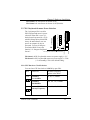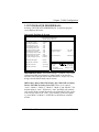
1
P6F91i Quick Reference
R
intel Pentium II & Celeron CPU Soft-Menu Settings
1) Turn the system on, then press <DEL> key to access the AWARD BIOS
SETUP program. A “CMOS SETUP UTILITY” will display on the screen.
Select “LOAD SETUP DEFAULTS” and type “Y” to load BIOS optimal
setup.
2) After the BIOS optimal setting is set, at the top right hand side of the
“Chipset Feature Setup” screen, there is a “CPU Speed” options. Refer
to the table below and select the correct CPU speed.
3) Select “STANDARD CMOS SETUP” to set the Date /Time, Floppy drive
type, and set Hard Disk Type to “Auto”.
4) Select “SAVE & EXIT SETUP” and press the <Enter> key to save the setting information in the CMOS memory and continue with the booting process.
CPU Bus Clock=100MHz:
CPU SPEED
Soft-Menu Setting
350MHz
100MHz
3.5
400MHz
100MHz
4.0
450MHz
100MHz
4.5
*500MHz
100MHz
5.0
CPU Bus Clock=66MHz:
CPU SPEED
Soft-Menu Setting
233MHz
66.6MHz
3.5
266MHz
66.6MHz
4.0
300MHz
66.6MHz
4.5
333MHz
66.6MHz
5.0
NOTE:
“*” Some higher frequency CPUs are not available yet, the clock setting for
those CPUs are for reference only.
FILE NAME:
F96x-1.DOC
082498
Copyright Notice
C
Copyright 1998.
The information contained in the user’s manual and all accompanying documentation is copyrighted and all rights are reserved.
This publication may not, in whole or in part, be reproduced,
transcribed, stored in a retrieval system, translated into any language or computer language, or transmitted in any form whatsoever without the prior written consent from the manufacturer,
except for copies retained by the purchasers for their personal
archival purposes.
The manufacturer reserves the right to revise this user’s manual
and all accompanying documentation and to make changes in the
content without obligation to notify any person or organization of
the revision or change.
IN NO EVENT WILL THE VENDOR BE LIABLE FOR
DIRECT, INDIRECT, SPECIAL, INCIDENTAL, OR CONSEQUENTIAL DAMAGES ARISING OUT OF THE USE OR
INABILITY TO USE THIS PRODUCT OR DOCUMENTATION, EVEN IF ADVISED OF THE POSSIBILITY OF SUCH
DAMAGES. IN PARTICULAR, THE VENDOR SHALL NOT
HAVE LIABILITY FOR ANY HARDWARE, SOFTWARE,
OR DATA STORED OR USED WITH THE PRODUCT,
INCLUDING THE COSTS OF REPAIRING, REPLACING, OR
RECOVERING SUCH HARDWARE, SOFTWARE, OR
DATA.
All trademarks mentioned in this document are acknowledged.
The Specification on the manual is subject to change without
notice.
2
P6F91i User’s Manual
Table Of Contents
Chapter 1
Introduction
1.1 Overview
1.2 P6F91i Specifications/Features
1.3 P6F91i Mainboard Layout
1.4 Microprocessor
1.5 Pentium II Packaging
1.6 Chipset
1.7 Main Memory
1.8 Accelerated Graphics Port (AGP) slot
1.9 Enhanced IDE Support
1.10 Keyboard, Mouse and USB Interface
1.11 Real-time Clock, CMOS RAM and Battery
1.12 IrDA Infrared Support
1.13 Power Management
1.14 System Power On/Off Control
1.15 System Sleep / Resume
1.16 System Manageability
1.17 Wake On LAN (WOL)
5
7
10
11
11
11
12
13
13
14
15
15
15
16
17
17
17
Chapter 2
Hardware Installation
2.1 Unpacking
2.2 Installation
2.2.1 Attaching Connectors
2.2.2 Installing CPU
2.2.3 Removing the Processor
2.2.4 Installing System Memory
2.2.5 Clear CMOS and Password
2.2.6 Auto Power On
2.2.7 PS/2 keyboard & mouse Power Selection
2.2.8 CPU Bus Over-Clock Selection
2.2.9 Intel Pentium II CPU Soft-Menu Setting
2.2.10 System Clock (CPU Bus Clock)
18
18
20
25
28
29
30
30
31
31
32
34
P6F91i User’s Manual
3
4
Chapter 3
BIOS Configuration
3.1 Entering Setup
3.2 CMOS Setup Utility
3.3 Standard CMOS Setup
3.4 IDE HDD Auto Detection
3.5 Load Setup Defaults
3.6 Save & Exit Setup
3.7 Exit Without Saving
3.8 BIOS Features Setup
3.9 Chipset Features Setup
3.10 Power Management Setup
3.11 PnP/PCI Configuration
3.12 Integrated Peripherals
3.13 Supervisor / User Password
36
37
38
40
41
41
41
42
45
49
53
55
58
Chapter 4
Driver and Utility
4.1 Flash Utility
4.2 EIDE Bus Master Driver
4.3 System Environment Monitor
4.3.1 Hardware Doctor Setup
4.3.2 Setting the Threshold
59
59
60
60
62
P6F91i User’s Manual
Chapter 1: Introduction
1 Introduction
1.1 Overview
The P6F91i is a high quality, high performance, function enhanced
mainboard, based on the powerful Intel Pentium II processor operating
at 233, 266, 300, 350, 400, 450, 500*MHz and Intel Celeron processor
operating at 266, 300MHz or faster CPU in the future. This mainboard is
designed around the latest and fastest Intel 82440BX chipset in a
standard ATX form factor. The Soft-menu (jumperless) design of the
P6F91i uses the onboard BIOS for clock frequency, and CPU multiplier,
jumper settings are no longer needed.
The P6F91i mainboard delivers workstation level performance with its
integrated AGP (Accelerated Graphics Port), Bus Mastering EIDE
(Enhanced IDE) controller, concurrent PCI bus, and its ability to
accommodate EDO (Extended Data Out) and SDRAM (Synchronous
DRAM) memory. When this high data stream bandwidth mainboard is
equipped with a powerful 64-bit Pentium II processor with MMX
technology and with a CPU built-in 512KB level 2 cache, your system
has the power to handle future demanding communication, multi-media,
multi-tasking and intensive 32-bit applications on advanced 32-bit
operating systems.
The P6F91i mainboard achieves the highest reliability by supporting the
ECC (Error Checking and Correction) memory protection. This enables
the P6F91i mainboard to achieve superior data integrity and faulttolerance, in respect to memory errors while running applications.
The P6F91i mainboard offers outstanding I/O capabilities. It contains a
full set of PC I/O, such as dual channel PCI EIDE interfaces, a floppy
controller, two FIFOed serial port connectors, an EPP/ECP capable
bidirectional parallel port connector, an IrDA compatible infrared port,
dual USB (Universal Serial Bus) connector, and a PS/2 keyboard
connector and a PS/2 mouse connector. One AGP slot, five PCI local
bus slots and two ISA bus slots provide expandability for add on
peripheral cards.
* Some higher frequency CPUs are not available yet, the clock setting for those CPUs are for
reference only.
P6F91i User’s Manual
5
Chapter 1: Introduction
The P6F91i mainboard is OnNow PC, Managed PC, ACPI and
PC98 compliant. It also offers optimized system performance,
integrated power management, system manageability, Trend
Chipaway Virus and Creative SoundBlaster Link.
Optimized System Performance: AGP improves the Graphics
performance dramatically, Ultra DMA/33 speeds up disk drive
access, Enhanced SDRAM support for fastest access to memory,
and Concurrent PCI enables simultaneous data transfer.
Integrated Power Management: ACPI (Advanced Configuration
and Power Interface) support enables O/S and application
programs to direct the system power management.
System Manageability: Winbond W83781D Hardware
Environment Monitoring chip enables the ability for system
voltage, temperature and fan speed monitoring.
Trend Chipaway Virus(TCAV): This unique, specially designed
solution stops boot viruses from infecting the boot sector or
partition table during the “threat” period that exists before the boot
sector loads and traditional anti-virus protection takes effect.
Trend ChipAway Virus resides in the BIOS to prevent boot
viruses from causing any damage to computers.
Creative SoundBlaster (SB-Link): This 2x3 5 pin header enables
the migration of Creative Soundblaster DOS program
compatibility to the PCI bus. Some DOS programs require the use
of signals which were previously only available to an ISA bus
card. These signals have now been made available to a PCI bus
card which may require them, through the use of this header.
In addition to superior hardware capabilities, features like bus
mastering EIDE driver, Plug and Play, Soft-off, APM (Advanced
Power Management), Keyboard Turn On, External Modem Ring
On, Wake On LAN (WOL), Watchdog timer wake up, Sleeping
state indicator, fan off in sleeping state and BIOS upgradability are
provided on the P6F91i platform.
6
P6F91i User’s Manual
Chapter 1: Introduction
1.2 P6F91i Specifications/Features
Hardware
CPU
Supports Intel Pentium II 233, 266, 300 and 333MHz
Supports Intel Pentium II 350, 400, 450 and 500*MHz
Supports Intel Celeron 266, 300MHz
VRM
Voltage Regulator Module on board
Provides 1.8V to 3.5V operating voltage
Coprocessor
CPU built-in floating point unit
Speed
System bus clock 66/68/75/83MHz
System bus clock 100/103/112/133MHz
AGP clock 66/68/75/83 MHz
PCI bus clock 33/34/37/40.1 MHz
ISA bus clock 8.33~9.35 MHz
Chipset
Intel’s 82440BX AGPset
Winbond’s W83977 I/O chip
Winbond’s W83781D PC Environment Monitor chip
L2 Cache
CPU built-in or none cache
DRAM
3 x 168-pin DIMM sockets
Supports 8MB to 384MB memory
Supports EDO and SDRAM memory
EIDE Controller Supports four IDE devices in two channels
Supports PIO mode 0 through mode 4 drives
Supports Bus Mastering DMA mode 2 drives
Supports Bus Mastering Ultra DMA/33 drives
Enhanced I/O
One floppy disk controller
One Standard/EPP/ECP parallel port connector
Two 16550 compatible serial port connectors
One IrDA compatible Infrared port
Two USB (Universal Serial Bus) connectors
* Some higher frequency CPUs are not available yet, the clock setting for those
CPUs are for reference only.
P6F91i User’s Manual
7
Chapter 1: Introduction
Mouse/Keyboard
PS/2 mouse connector
PS/2 keyboard connector
Expansion Slots
One AGP Slot
Five 32-bit PCI slots
Two 16-bit ISA slots (one PCI/ISA shared slot)
Power Management
Compliant with EPA, APM 1.2 and ACPI
ATX soft-off power control
Power - On by Keyboard
Power - On by External Modem Ring
Power - On by Alarm
Power - On by Wake On LAN (WOL)
Sleep state indicator
Fan off in sleep mode
System Management Winbond W83781D PC Environment Monitor
CPU temperature warning and System
temperature detection
CPU and System voltage detection
CPU and Secondary FAN RPM detection
Voltage Regulator
Switching regulator
CPU voltage auto-detection
Form Factor
ATX Form Factor, 19cm x 30.5cm (7.5"x 12.0")
Software
8
BIOS
Soft-Menu (Jumperless) design
Built-in Trend Chipaway Virus(TCAV)
AWARD Pentium II AGP/PCI BIOS
Flash BIOS with ESCD (Extended System
Configuration Data) block
Supports APM, PnP, Multi-Boot, DMI and
EIDE devices
Supports High-Capacity LS-120 and ZIP
Removable Media Drive
Driver
IDE Bus mastering Ultra DMA driver
P6F91i User’s Manual
Chapter 1: Introduction
Utility
Flash utility for BIOS upgrade
System Environment Monitoring Utility
O.S.
Operates with MS_DOS, Windows 3.x,
Windows for Work Groups 3.x, Windows 95,
Windows NT, OS/2, Novell Netware, Novell
UnixWare 1.1 and SCO Unix 4.2
Environment
Ambient Temperature
Relative Humidity
Vibration
DC Voltage
DC Voltage
DC Voltage
P6F91i User’s Manual
00C to 500C (Operating)
0 to 85% (Operating)
0 to 500 Hz
4.9V to 5.2V
3.15V to 3.50V
-5V, +12V, -12V, +5VSB 5% tolerance.
9
Chapter 1: Introduction
1.3 P6F91i Mainboard Layout
2
14
JP13
1
19
21
1
JP12
12
9
1
18
IR
82371EB
3
1
JP15
22
W83977
23
4
1
JP1
DIMM 1
JP16
DIMM 2
DIMM 3
15
20
1
1
1
17
7
13
5
CPU Slot 1
82443BX
6
1
BANK 0
BANK 1
BANK 2
16
9:IR Port Header
10:ATX Power Connector
11:PS/2 Mouse Connector (T)
PS/2 Keyboard Connector (B)
12:Flash BIOS
13:Switching Regulator
14:Front panel Connectors
15:Battery (CR2032 Lithium)
1
10
10
JP6
1:CPU Slot1
2:ISA Expansion Slots
3:PCI Expansion Slots
4:AGP Slot
5:DIMM Module Sockets
6:IDE Connectors
7:Floppy Drive Connector
8:Parallel Port Connector (T)
Serial Port Connectors (B)
8
11
16:Dual USB Connector
17:CPU FAN Connector
18:Secondary FAN Connector
19:System Monitor W83781D
20: Wake On LAN Header
21: Auto Power On (JP13)
22: Creative Lab SB-Link(JP15)
23: 66/100MHz Selection(JP16)
P6F91i User’s Manual
Chapter 1: Introduction
1.4 Microprocessor
The P6F91i mainboard is designed to operate with the Intel Pentium II
processor that runs at 233, 266, 300, 333, 350, 400, 450 and 500*MHz
and Intel Celeron processor operating at 266, 300MHz or faster CPU
in the future. An on board switching voltage regulator provides the
required 1.8 to 3.5 volts for the processor. The Pentium II processor
will send 5 VID (Voltage Identification) signals to the switching
voltage regulator, and the switching regulator will generate the correct
voltage for the processor.
The Pentium II processor implements MMX technology and
maintains full backward compatibility with the 486 and Pentium
processors. The processor’s numeric coprocessor significantly
increases the speed of floating-point operations.
1.5 Pentium II Packaging
The Pentium II is packaged in an S.E.C. (Single Edge Connector)
cartridge. The S.E.C. cartridge includes the processor core, the secondlevel cache, a thermal plate, and a back cover. The Pentium II
connects to the P6F91i mainboard through the Slot 1 processor
connector, a 242-pin edge connector. When the Pentium II is installed
in Slot 1, it is secured by a retention mechanism attached to the
mainboard. The Pentium II heatsink is stabilized by a heatsink
support, which is attached to the mainboard.
1.6 Chipset
The Intel 82440BX AGPset consists of one 82443BX (PAC) System
Controller, and one 82371EB (PIIX4E) PCI ISA/IDE Accelerator.
82443BX (PAC):
P6F91i User’s Manual
- CPU interface controller
- AGP Interface controller
- Integrated DRAM controller
- Fully synchronous PCI 2.1 bus interface
- Extensive CPU-to-AGP, CPU-to-DRAM,
CPU-to-PCI, AGP-to-DRAM, AGP-toPCI, PCI-to-AGP and PCI-to-DRAM data
buffering
11
Chapter 1: Introduction
82371EB (PIIX4E):
- Interface between the PCI and ISA buses
- Power Management Logic
- USB controller
- EIDE controller
- Seven DMA channels, one timer/counter,
two eight-channel interrupt controllers,
NMI logic, SMI interrupt logic, and PCI/
ISA bus arbitrator
- SMBus interface
- Real-Time clock
1.7 Main Memory
The P6F91i mainboard provides three 168-pin DIMM sockets to
support 64-bit or 72-bit (64-bit memory data plus 8-bit ECC)
DRAM array. The total memory size can support from 8MB to
384MB. The sockets support 1M x 64 (8MB), 2M x 64 (16MB), 4M
x 64 (32MB), 8M x 64 (64MB) and 16Mx64(128MB) DIMM in
single or double-sided modules.
The P6F91i supports two types of DRAMs, Extended Data Out
(EDO) and Synchronous DRAM (SDRAM). Memory Timing
requires 60ns or faster for EDO, and SDRAM speed grade needs to
match CPU bus clock speed. For example, if the Intel Pentium II
350, 400, 450, 500MHz CPU bus clock is 100MHz, then speed
grade for SDRAM is 100MHz. Intel Pentium II 233, 266, 300,
333MHz CPU bus clock is 66.6MHz, then speed grade for SDRAM
is 66.6MHz. Each DIMM belongs to different banks, each bank can
have different size or speed of memory. SDRAM and EDO
DIMMs can not be mixed within the memory array. There are no
jumper settings required for the memory size and type, which are
automatically detected by the BIOS.
The P6F91i mainboard achieves the highest reliability by supporting
the ECC (Error Checking and Correction) memory protection
(SDRAM only). The ECC is a hardware scheme which detects all
single and dual-bit errors, and corrects all single-bit error during
main memory access. The ECC can be supported only if all the
SDRAM DIMM memory modules come with parity bits.
12
P6F91i User’s Manual
Chapter 1: Introduction
1.8 Accelerated Graphics Port (AGP) Slot
The P6F91i mainboard is equipped with an Accelerated Graphic Port
slot which is compliant to the AGP specification. The AGP runs at
66.6MHz clock and supports both 1x and 2x mode for 66.6MHz and
133MHz 3.3V devices. The data transfer rate on the AGP bus may be
4 times faster than PCI bus.
The following is a clock frequency for different CPU Bus Clock
operating modes:
CPU Bus Clock
AGP Clock PCI Clock
ISA Clock
100MHz
66MHz
33MHz
8.3MHz
103MHz
68.6MHz
34MHz
8.5MHz
112MHz
74.7MHz
37.5MHz
9.4MHz
66MHz
66MHz
33MHz
8.3MHz
68MHz
68MHz
34MHz
8.5MHz
75MHz
75MHz
37.5MHz
9.4MHz
1.9 Enhanced IDE Support
The P6F91i mainboard provides two enhanced high performance
PCI IDE interfaces capable of supporting four devices with PIO
mode 0 through mode 4, bus-mastering DMA mode 2, and busmastering Ultra DMA/33 ATAPI devices. Detection of IDE device
type and transfer rate is automatically performed by the BIOS. The
traditional PIO IDE device requires a substantial amount of CPU
bandwidth to handle all the activities of IDE access including
waiting for mechanical activities. The Bus Master logic designed in
the Intel 82440BX chipset is intended to reduce the workload of the
CPU, hence increasing CPU efficiency. The Bus Master takes care
of the data transfer between IDE and memory, and lets the CPU
handle other tasks. In true multi-tasking operating systems such as
Windows 95, Windows NT, and OS/2, by using bus-mastering IDE,
the CPU workload can be reduced to complete other tasks while disk
data transfers are occurring. The driver must be loaded in order to
make the EIDE drive operate in bus-mastering DMA mode.
P6F91i User’s Manual
13
Chapter 1: Introduction
The following is a data transfer rate comparison table for different
IDE operating modes:
Operating Mode
Maximum Data Transfer Rate
PIO Mode 3
11.1 MB/Second
PIO Mode 4
16.6 MB/Second
DMA Mode 1
13.3 MB/Second
DMA Mode 2
16.6 MB/Second
Ultra DMA/33
33.2MB/Second
1.10 Keyboard, Mouse and USB Interface
PS/2 keyboard, PS/2 mouse, and USB connectors are located on the
back panel of the P6F91i mainboard. The 5V line to the PS/2
Keyboard and PS/2 Mouse connectors are protected with a
PolySwitch circuit that acts like a rehealing fuse which will reestablishing the connection after an over-current condition is
removed. While this device eliminates the possibility of replacing
the fuse, you will still need to turn off the system power before
connecting or disconnecting a keyboard or a mouse.
The P6F91i mainboard has a dual USB connector to support two USB
ports. The USB is a serial bus interface standard that is designed to
bring the “Plug and Play” concept to the outside of the computer
system chassis. The bus allows devices to be attached, configured,
used and detached while the host system is in operation.
The USB will allow as many as 63 devices to be daisy chained in any
combination per port. With up to 12Mbits/sec transfer rate, the USB is
suitable for devices such as keyboard, mouse, digital joystick, game
pad, fax/modem, scanner, printer, ISDN and telephony device.
14
P6F91i User’s Manual
Chapter 1: Introduction
1.11 Real-time Clock, CMOS RAM and Battery
The integrated real-time clock (RTC) provides a time of day clock,
and an 85-year calendar with alarm features. P6F91i also has 242
bytes battery backed CMOS RAM which stores the system setup
information and password. The RTC and CMOS RAM can be set via
the BIOS SETUP program. The contents of the CMOS RAM can be
cleared by placing a shunt to short pin2 and pin3 of JP12 for 5 seconds
when the system power is off.
A coin-cell style Lithium CR2032 battery is used to provide power to
the RTC and CMOS memory. The battery has a three year life if the
system is not powered up. When the system powers up, the power for
the RTC and CMOS RAM is supplied from the 5 V power supply to
extend the life of the battery.
1.12 IrDA Infrared Support
A 5-pin header connector is used to connect a Hewlett Packard
HSDSL-1000 compatible IrDA or Sharp ASKIR Infrared module.
Once the module is installed, the user can use application software
such as Microsoft Infrared (MSIR) to transfer files between the
computer system and portable devices such as laptops and printers.
1.13 Power Management
The integrated DPMA (Dynamic Power Management Architecture)
features in the Intel 440BX AGPset go far beyond the original vision
of the “Green PC” to create exciting new application models for the
“OnNow” PC platform. The “OnNow” PC is a PC which is always
on and ready for use but appears to be off when not in use. The
P6F91i not only complies with EPA, APM1.2 and ACPI (Advanced
Configuration and Power Interface), but also provides the following
power management features.
- Power-on by a external modem ring in or a watchdog timer (Alarm)
System could be powered on by phone ring, or by software that has
requested the PC to wake up at a preset time.
P6F91i User’s Manual
15
Chapter 1: Introduction
- Suspend mode indicator
The power LED becomes dim when system is in suspend mode.
- Fan off in suspend mode
The CPU cooling fan will be turned off when the system is in
suspend mode.
1.14 System Power On/Off Control
System power can be turned on by a power button, an external modem
ring, an alarm, or a PS/2 Keyboard. To enable the “modem ring on”
feature, the option “Power-On by Ring” in the BIOS Power
Management Setup has to be set to “Enabled”. To enable the “alarm
on” feature, the option “Power -On by Alarm” in the BIOS Power
Management Setup has to be set to “Enabled”. To enable the “Power On by PS/2 Keyboard” feature, you need to short JP6 2-3 and set
“Power On Function” in the BIOS Integrated Peripherals Setup
accordingly.
System power can be turned off in one of two ways: a front panel
power button or soft-off control. When the option “Power-Off by
PWR-BTTN” in the BIOS Power Management Setup is set to “InstantOff”, pressing the power button will immediately turn off the system
power. But if the “Power-Off by PWR-BTTN” option is set to “Delay
4 Sec.”, you have to press the power button and hold it for more than 4
seconds to turn off the system power. The system power can also be
turned off via software control. The system BIOS will turn the system
power off when it receives the proper APM command from the
Operating System. For example, Windows 95 will issue Soft Off APM
command when the user selects “Shutdown” in Start Menu. In order
for the Soft Off feature to work properly, Power Management/APM
must be enabled in the system BIOS and Operating System.
The P6F91i Auto Power On feature gives you the option to turn on the
system power automatically after the AC power comes back, which is
especially useful for the server application. To enable this feature, you
need to shunt JP13 to 1-2. The default for JP13 is 2-3.
16
P6F91i User’s Manual
Chapter 1: Introduction
1.15 System Sleep / Resume
When Advanced Power Management (APM) is activated in the system
BIOS and the Operating System's APM/ACPI driver is loaded, Sleep
mode (Suspend) can be entered in one of three ways: press the front
panel power button, select “Suspend” in Windows 95 Start Menu or
no system activity for a pre-defined length of time. To use the power
button to control system sleep/resume, the option “Power-Off by PWRBTTN” in the BIOS Power Management Setup has to be set to “Delay
4 Sec.”
When the system enters the sleep mode, the CPU stops running, the
82440BX AGPset and related circuits stay in the lowest power state,
the HDD stops spinning, the monitor screen becomes blank, the power
LED indicator on the front panel dims, and the CPU cooling fan and
secondary fan are turned off (Note: in order to turn off the fan in sleep
mode, you need to connect the CPU cooling fan or Chassis fan to the
on-board fan power connectors marked FAN1 or FAN2).
1.16 System Manageability
The System Management Chip (Winbond W83781D) with software,
allows user to monitor system environment such as system and CPU
fan speed (requires fan with tachometer output), CPU warning
temperature, system temperature and system operating voltages.
1.17 Wake On LAN (WOL)
Wake on LAN (WOL) is a 1x3 pin header for remote wake up of the
computer through a network. Wake on LAN requires a PCI add-in
network interface card (NIC) with remote wake up capabilities. The
remote wake up header on the NIC must be connected to the onboard
Wake on LAN header. The NIC monitors network traffic at the MII
interface and when it detects a Magic Packet (MP Wake-up) it asserts
a wake up signal that powers up the computer.
Note: For Wake on LAN, the 5-V standby line of the power supply
must be capable of delivering 5V with 5% tolerance at 720mA.
P6F91i User’s Manual
17
Chapter 2:Hardware Installation
2 Hardware Installation
2.1 Unpacking
The P6F91i mainboard package contains the following:
r P6F91i mainboard
r One IDE 40-pin ribbon cable
r One floppy 34-pin ribbon cable
r Driver and Utility diskettes
r User's manual
r CPU retention mechanism
Before removing the mainboard from its anti-static bag, you need to
eliminate any static electricity that may be accumulated on your
body by touching a grounded or anti-static surface. If nothing is
available, touch the housing of the power supply which is plugged
into the AC outlet.
After removing the mainboard from its anti-static bag, place it only
on a grounded or anti-static surface, component side up. Inspect the
mainboard and call the vendor immediately if it is damaged.
2.2 Installation
The P6F91i is designed to fit into a standard ATX form factor
chassis. The pattern of the mounting holes and the position of the
back panel connectors meet the ATX system board specification.
The chassis may come with various mounting fasteners which are
made of metal or plastic. It is highly recommended to use as many
metal fasteners as possible to mount the mainboard in the chassis for
better grounding.
To install the mainboard you need to install CPU, DIMM memory
modules, attach the connectors and set correct CPU speed in the
CMOS setup.
18
P6F91i User’s Manual
Chapter 2: Hardware Installation
P6F91i Mainboard Connector/Jumper Location
ISA1
JP13
1
HDD STB
LED LED RESET PW SW
W83781D PC
Environment Monitor
Auto Power On Jumper
PCI 5
PCI 4
1
JP12
SPEAKER POWER LED&KEY LOCK
ISA2
CMOS RAM Clearance
IR
1
PCI 3
IR Connector
Secondary FAN Connector
JP15
1
1
JP10
PCI 2
Reserved (Factory Test)
Creative Lab SB-Link connector
PCI 1
1
AGP
JP1
JP16
CPU Bus Clock 66/100MHz Selection
Wake On LAN
Connector
1
1
1
FDC Connector
IDE1 Connector
IDE2 Connector
CPU Cooling FAN Connector
COM2 COM1
Parallel Port(TOP)
USB
ATX Power Connector
CPU Slot 1
PS/2 Keyboard
1
DIMM 1
DIMM 2
DIMM 3
PS/2 Mouse(TOP)
JP6
BANK 0
BANK 1
BANK 2
P6F91i User’s Manual
PS/2 keyboard & mouse Power Selection
19
Chapter 2:Hardware Installation
2.2.1 Attaching Connectors
1. Front Panel Connectors
There are 6 connectors on the mainboard for speaker, switches and
indicator lights on the system’s front panel.
HDD
LED
STB
POWER
LED RESET SWITCH
1
1
1
SPEAKER
1
1
1
KEYLOCK &
POWER LED
SPEAKER
1
Pin Assignment
1. Speaker out
2. Ground
3. Ground
4. +5V
This 4-pin connector connects to the case-mounted speaker.
KEYLOCK & Power LED
1
Pin Assignment
1. LED Cathode
2. N. C.
3. LED Anode (Ground)
4. KEYLOCK
5. Ground
This 5-pin connector connects to the case-mounted keylock switch and
the power LED. The keylock switch is used to lock the keyboard for
security purposes.
20
P6F91i User’s Manual
Chapter 2:Hardware Installation
HDD LED Connector
1
Pin Assignment
1. LED Anode
2. LED Cathode
This 2-pin connector connects to the case-mounted HDD LED to
indicate hard disk activity.
STB LED Connector
1
Pin Assignment
1. LED Cathode
2. LED Anode (Ground)
This 2-pin connector connects to the case-mounted STB LED to indicate
a standby status.
Reset Connector
1
Pin Assignment
1. Power Good
2. Ground
This 2-pin connector connects to the case-mounted reset switch and
is used to reboot the system.
Power Switch Connector
1
Pin Assignment
1. Power On/Off
2. Ground
This 2-pin connector connects to the case-mounted Power button.
The front panel on your case may have a turbo switch to deactivate the
Turbo mode when a slower speed is required for a specific application.
The Intel 82440BX chipset does not support the hardware deturbo function. An alternative method of using <CTRL><ALT><+/-> keys to
change the speed may be used if necessary.
P6F91i User’s Manual
21
Chapter 2:Hardware Installation
2. Fan Connectors
Pin Assignment
1. GND
2. +12V
3. SPEED / RPM
1
2
3
There are two fan connectors on the P6F91i mainboard for the cooling fans.
The connectors support fans of 12V DC/500mAMP (6 WATT) or less.
When the system goes into sleep state, fan should be shut down to eliminate
audible noise and reduce power consumption. You can monitor the fan speed
by way of W83781D chip and the fan must come with a tachometer output.
3. IrDA-compliant IR (Infrared) Connector
1
Pin Assignment
1. +5V
IrDA
2. IRM_IRR
Module
3. IR Receiver
4. Ground
5. IR Transmitter
This 5-pin connector connects to an optional wireless transmitting and receiving infrared module via a cable and a bracket.
4. Floppy Drive Connector (One 34-pin Block)
A floppy disk drive ribbon cable has 34 wires and 2 connectors to support
2 floppy disk drives. The connector with twisted wires always connects to
drive A, and the connector with untwisted wires connects to drive B. You
must orient the cable connector so that the pin 1(color) edge of the cable is
at the pin 1 of the I/O port connector.
5. IDE Connectors (Two 40-pin Block)
An IDE drive ribbon cable has 40 wires and 2 connectors to support two
IDE drives. If a ribbon cable connects to two IDE drives at the same
time, one of them has to be configured as Master and the other has to be
configured as Slave by setting the drive select jumpers on the drive.
22
P6F91i User’s Manual
Chapter 2:Hardware Installation
Consult the documentation that came with your IDE drive for details on
jumper locations and settings. You must orient the cable connector so
that the pin 1(color) edge of the cable is at the pin 1 of the I/O port connector.
6. Back Panel Connectors
The back panel provides external access to PS/2 style keyboard and
mouse connectors, two serial ports, one parallel port and dual USB port
which are integrated on the mainboard. The figure below shows the
location of the back panel I/O connectors.
PS/2 Mouse (TOP)
Parallel Port (TOP)
USB1
PS/2 Keyboard USB2
COM1
REAR VIEW
COM2
PCB
7. Power Supply Connector
The ATX power supply has a single lead con+3.3V
+3.3V
nector with a clip on one side of the plastic
-12V
+3.3V
housing. There is only one way to plug the lead
Ground
Ground
Power ON/OFF
+5V
into the ATX power connector. Press the lead
Ground
Ground
connector down until the clip snaps into place
Ground
+5V
and secures the lead onto the connector.
Ground
Ground
-5V
Power Good
+5V
+5VSB
+5V
+12V
Incorrect installation of the power supply could result in serious damage to
the mainboard and connected peripherals. Make sure the power supply is
unplugged from the AC outlet before connecting the leads from the power
supply.
P6F91i User’s Manual
23
Chapter 2:Hardware Installation
8. Wake on LAN Connector:
This 3-pin header is used for remote wake up of the computer through a
network.
Pin Assignment
1. +5VSB
2. GND
3. Wake-up signal
1
JP1
9. Creative Lab SB (Side-band)-Link Connector:
This 2x3 ways, straight-3 header is used for Creative Lab PCI sound card
(Ex. AWE64D PCI Audio Wave Table Card). In order to migrate the
legacy Sound Blaster compatible audio to the PCI bus, the following
signals have to be delivered to the PCI audio card through a flat cable.
1
2
4
6
3
5
JP15
24
Pin Assignment
1. Grant
2. GND
3. N.C.(Key Pin)
4. Request
5. GND
6. SER_IRQ
P6F91i User’s Manual
Chapter 2:Hardware Installation
2.2.2 Installing CPU
Before You Begin
1. Be sure that your Intel processor kit includes the following items:
· the processor with the fan or heatsink attached
· one heatsink support set containing two black plastic pegs and
two black plastic supports.
· one power cable (for CPU with cooling fan attached only)
2. Place the motherboard on a workbench (not in a chassis). Be sure
that the motherboard is bare (that is, no DIMMs, cables, or cards
are installed) and that the holes for the fan or heatsink support pegs
are empty.
3. Install the retention mechanism onto the motherboard by following
the manufacturer’s instructions. (Shown installed in the following
figure.)
Installing the Boxed Processor
1. Mount the two black plastic pegs onto the motherboard. These pegs
will be used to attach the fan or heatsink supports. Notice that one
hole and the base of one peg are larger than the other hole and peg
base. Push each peg into its hole firmly until you hear it “click” into
place.
2. Slide a black plastic support onto each end of the fan or heatsink,
making sure that the hole and clip are on the outside edge of the support. (If supports are reversed, the holes will not line up with the pegs
on the motherboard.) Slide each support toward the center of the processor until the support is seated in the outside groove of the fan
housing.
P6F91i User’s Manual
25
Chapter 2:Hardware Installation
3. Slide the clip (A) on each support toward the processor, exposing the
hole that will fit over the peg on the motherboard. Push the latches
(B) on the processor toward the center of the processor until they
click into place. (Refer to the figure below.)
4. Hold the processor so that the fan shroud is facing toward the pegs on
the motherboard. Slide the processor (C) into the retention mechanism and slide the supports onto the pegs. Ensure that the pegs on the
motherboard slide into the holes in the heatsink support and that the
alignment notch in the processor fits over the plug in Slot 1. Push the
processor down firmly, with even pressure on both sides of the top,
until it is seated.
5. Slide the clips on the supports (D) forward until they click into places
to hold the pegs securely. (Apply slight pressure on the peg and push
the peg toward the clip while pushing the clip forward.) Push the
latches on the processor (E) outward until they click into place in the
retention mechanism. The latches must be secured for proper electrical connection of the processor.
26
P6F91i User’s Manual
Chapter 2:Hardware Installation
6. Attach the small end of the power cable (F) to the three-pin
connector on the processor, then attach the large end to the three-pin
connector on the motherboard, which is marked FAN1.
Installing the Celeron (S.E.P Processor)
•Line up the SEPP/heatsink,
ensuring that the substrate key is
lined up with the slot 1 connector.
•Insert SEPP into the guide rails
along the retention mechanism.
•Place one hand on the SEPP/
heatsink combination and push
into the slot 1 connector. Insertion and extraction forces are
specified at 25 lbs.
•You will hear a click as the
retention mechanism pops back,
thereby firmly locking the processor into the slot 1 connector.
P6F91i User’s Manual
27
Chapter 2:Hardware Installation
2.2.3 Removing the Processor
First, remove the motherboard from the chassis. To remove the processor from the motherboard, follow these steps (the reverse of the
installation procedure).
1. Disconnect the fan power cable from the motherboard. (We recommend that you leave the cable connected to the processor.)
2. Slide the clips on the supports backward to release the pegs in the
motherboard. Push the latches on the processor toward the center
of the processor until they click into place.
3. Lift one end of the processor until it is freed from Slot 1. Lift the
other end of the processor until it is freed from Slot 1. Lift the
entire processor (with the fan or heatsink supports attached) until
it is free from the retention mechanism.
4. Remove the heatsink support pegs from the motherboard and discard them. With one hand, squeeze together the two halves of the
peg on the bottom side of the motherboard. With the other hand,
pull the peg out of the hole in the motherboard. Do not reuse the
pegs.
MWhen handling the processor, avoid placing direct pressure
on the label area of the fan.
MWhen removing the processor, avoid pressing down on the
motherboard or components. Instead, press down on plastic
connectors.
28
P6F91i User’s Manual
Chapter 2:Hardware Installation
DIMM 1
DIMM 2
BANK 0
BANK 1
BANK 2
P6F91i User’s Manual
FDD Connector
Single-Sided
Symmetric: 1Mx64, 4Mx64,
16Mx64
Asymmetric: 1Mx64, 2Mx64,
4Mx64, 8Mx64
Double-Sided
Symmetric: 2Mx64, 8Mx64
Asymmetric: 2Mx64, 4Mx64,
8Mx64, 16Mx64,
32Mx64
Requirements DRAM Speed: 60ns or faster
RAS Access Time: 60ns or faster
CAS Access Time: 20ns or faster
IDE1 Connector
Module Size
1
EDO
(Extended Data Output)
IDE2 Connector
DRAM
TYPE
1
The P6F91i Mainboard has three DIMM
Sockets. Memory can be installed by using
168-pin SDRAM DIMM or EDO DIMM
memory modules. There are no jumper settings required for the memory size or type,
which is automatically detected by the
BIOS. Due to the P6F91i Mainboard high
speed design, the memory modules for the
P6F91i must meet all of the following
requirement:
1
The maximum system memory supported
by the P6F91i is 384MB. If more than
384MB memory are populated on the
P6F91i mainboard, the portion of the
memory which exceed the 384MB
boundary will be invalidated.
DIMM 3
2.2.4 Installing System Memory
SDRAM
(Synchronous DRAM)
Single-sided
Asymmetric: 1Mx64, 2Mx64,
4Mx64, 8Mx64,
16Mx64,
Double-Sided
Asymmetric: 2Mx64, 4Mx64,
8Mx64,
16Mx64,
32Mx64
3.3V unbuffered DIMM
module
Speed grade: Have to match
the CPU Bus clock speed
(66MHz or 100MHz) or
faster.
CAS latency: 3 or faster
29
Chapter 2:Hardware Installation
Install 168-pin DIMM modules in any combination as follows:
168-Pin DIMM Modules Memory Configuration.
BANK 0
(DIMM1)
SDRAM/EDO 8MB, 16MB, 32MB, 64MB, 128MB
BANK 1
(DIMM2)
SDRAM/EDO 8MB, 16MB, 32MB, 64MB, 128MB
BANK 2
(DIMM3)
SDRAM/EDO 8MB, 16MB, 32MB, 64MB, 128MB
Total
System Memory
8MB to Max. 384MB
NOTE:
1. P6F91i does not support mixing of SDRAM and EDO memory
2. When using SDRAM with 4Mx4 and 16Mx4 chips, only registered
DIMMs can be used.
2.2.5 Clear CMOS and Password
If your system can not boot up because you forget your password,
or the CMOS settings need to be reset to default values after the
system BIOS has been updated, the following instructions can be
performed to clear the CMOS and password.
1. Power off the system
2. Place a shunt to short pin2 and pin3 of JP12 for 5 seconds
3. Put the shunt back to pin1 and pin2 of JP12
4. Power on the system
2.2.6 Auto Power On
After losing AC power, the system will not turn on automatically
when power comes back unless you set the Auto Power On jumper
(JP13) to 1-2. Out of safety consideration the default setting on JP13
is 2-3, which avoid system turn on by itself when plug in the power
cole.
30
P6F91i User’s Manual
Chapter 2:Hardware Installation
JP13 shunt 1-2: Auto Power On feature is On
JP13 shunt 2-3: Auto Power On feature is Off (Default).
2.2.7 PS/2 keyboard & mouse Power Selection
COM2 COM1
Parallel Port(TOP)
USB
PS/2 Keyboard
1
JP6
PS/2 Mouse(TOP)
ATX Power Connector
CPU Slot 1
The 3 pin jumper JP6 is used for
PS/2 keyboard and mouse’s power
selection. When JP6 is set to 2-3,
the keyboard is powered by +5Vsb
which will keep the keyboard LED
always lit and indicates user can
power on computer by key-in
password. You can set the password in the BIOS “Power On
function” of “Integrate Peripheral
Screen”.
PS/2 keyboard & mouse Power Selection
JP6 shunt 1-2: PS/2 keyboard & mouse use power supply’s +5V.
JP6 shunt 2-3: PS/2 keyboard & mouse use power supply’s +5Vsb
(+5 volt standby). This is the default setting.
2.2.8. CPU Bus Over-Clock Selection:
You can force CPU bus clock to 100MHz by open JP16.
JP16
Install CPU
Available Frequency
options in the BIOS
Close
Pentium II
233~333MHz:
66, 68, 75, 83MHz
JP16
Pentium II
350~500MHz:
100, 103, 112, 133MHz
Open
Pentium II CPU
with any Frequency:
100, 103, 112,133MHz
JP16
P6F91i User’s Manual
31
Chapter 2:Hardware Installation
2.2.9 Intel Pentium II CPU Soft-Menu Setting
The Soft-Menu (jumperless) design of the P6F91i allows the user to
set CPU Bus Clock and CPU core to Bus clock multiplier through
the BIOS.
CPU Bus Clock: The CPU Bus Clock is defined as the CPU input
clock. For example; the CPU Bus Clock for Intel Pentium II 350,
400, 450 and 500MHz is 100MHz and the CPU Bus Clock for Intel
Pentium II 233, 266, 300 and 333MHz is 66.6MHz.
CPU Core to Bus Clock Multiplier: The CPU internal core clock
is equal to the “CPU Bus Clock” times the “CPU Core to Bus Clock
Multiplier”. For example, if the CPU Bus Clock is 100MHz and the
CPU Core to Bus clock Multiplier is 3.5, the actual CPU core clock
will be 350MHz.
CPU Voltage: There is no hardware or BIOS settings needed for
CPU operating voltage. The switching regulator circuit can autodetect the CPU type on the P6F91i mainboard and generate the
proper operating voltage for the CPU.
Follows these three steps to setup CPU speed.
1) Turn the system on, then press <DEL> key to access the
AWARD BIOS SETUP program. A “CMOS SETUP UTILITY” will
display on the screen. At “CMOS SETUP UTILITY” screen
selects “Chipset Features Setup” and press <Enter>.
ROM PCI/ISA BIOS (2A69KF29)
CMOS SETUP UTILITY
AWARD SOFTWARE, INC.
STANDARD CMOS SETUP
BIOS FEATURES SETUP
IDE HDD AUTO DETECTION
CHIPSET FEATURES SETUP
LOAD SETUP DEFAULTS
POWER MANAGEMENT SETUP
SAVE & EXIT SETUP
PNP/PCI CONFIGURATION
EXIT WITHOUT SAVING
INTEGRATED PERIPHERALS
E
SUPERVISOR PASSWORD
USER PASSWORD
Esc: Quit
F10: Save & Exit Setup
32
<Shift>F2
: Select Item
: Change Color
P6F91i User’s Manual
Chapter 2:Hardware Installation
2) On the top right hand side of the “Chipset Feature Setup” screen,
there is a “CPU Speed” option. Refer to the table below and select
the correct CPU speed.
ROM PCI/ISA BIOS (2A69KF29)
CHIPSET FEATURES SETUP
AWARD SOFTWARE, INC.
Auto Configuration
EDO DRAM Speed Selection
EDO CASx# MA Wait State
EDO RASx# Wait State
:
:
:
:
SDRAM CAS Latency Time
: 2
DRAM Data Integrity Mode
: Non-ECC
System BIOS Cacheable
Video BIOS Cacheable
Video RAM Cacheable
: Enabled
: Enabled
: Disabled
8 Bit I/O Recovery Time
16 Bit I/O Recovery Time
: 1
: 1
Memory Hole At 15M-16M
: Disabled
Passive Release
Delayed Transaction
: Enabled
: Disabled
CPU Speed
Enabled
60 ns
2
2
: 350Mhz(100x3.5)
AGP Aperture Size (MB) :
Auto Detect DIMM/PCI Clk:
Spread Spectrum Modulated:
CPU Warning Temperature :
E
64
Enabled
Enabled
660C/1510F
Current System Temp. : 480C/1200F
Current CPU FAN Speed : 4383
Current FAN2 Speed
: 4353
Vcc3
: +3.32 Vccp : +2.80
+ 12V : +12.01 +5V : +5.01
- 5V
: -4.98 - 12V : -11.96
ESC: Quit
:Select Item
F1: Help
PU/PD/+/-:Modify
F5: Old Values
(Shift) F2: Color
F7: Load Setup Defaults
CPU Bus Clock=100MHz:
CPU
SPEED
Soft-Menu Setting
Bus Clock
Core to Bus Clock Multiplier
350MHz
100MHz
3.5
400MHz
100MHz
4.0
450MHz
100MHz
4.5
500MHz
100MHz
5.0
CPU Bus Clock=66MHz:
CPU
SPEED
Soft-Menu Setting
Bus Clock
Core to Bus Clock Multiplier
233MHz
66.6MHz
3.5
266MHz
66.6MHz
4.0
300MHz
66.6MHz
4.5
333MHz
66.6MHz
5.0
P6F91i User’s Manual
33
Chapter 2:Hardware Installation
3) After the “CPU Speed” is set, go back to “CMOS SETUP UTILITY” screen and select “SAVE & EXIT SETUP” and press the
<Enter> key to save the setting information in the CMOS memory and
continue with the booting process.
ROM PCI/ISA BIOS (2A69KF29)
CMOS SETUP UTILITY
AWARD SOFTWARE, INC.
STANDARD CMOS SETUP
F
BIOS FEATURES SETUP
IDE HDD AUTO DETECTION
CHIPSET FEATURES SETUP
LOAD SETUP DEFAULTS
POWER MANAGEMENT SETUP
SAVE & EXIT SETUP
PNP/PCI CONFIGURATION
EXIT WITHOUT SAVING
INTEGRATED PERIPHERALS
SUPERVISOR PASSWORD
USER PASSWORD
Esc: Quit
F10: Save & Exit Setup
<Shift>F2
: Select Item
: Change Color
2.2.10 System Clock (CPU Bus Clock)
When “CPU SPEED” set to “manual”, which allows user to set
“CPU Ratio” and “CPU Frequency” manually. The available
options for “CPU Frequency” are “66MHz”, “68MHz”, “75MHz”
and “83MHz” when a Intel Pentium II 233, 266, 300, 333MHz
CPU installed and “100MHz”, “103MHz”, “112MHz”, “133MHz”
when an Intel Pentium II 350, 400, 450, 500MHz CPU installed
You can over clock the CPU Bus frequency from 66MHz to
100MHz by change the jumper JP16. This give you the possibility
to over clock a 66MHz Pentium II CPU at 100MHz frequency.
34
JP16
CPU Bus Clock
Close (default)
Determines by the CPU Type
Open
Fixed at 100MHz
P6F91i User’s Manual
Chapter 2:Hardware Installation
.
Available Options for CPU Bus Clock
Installed CPU
JP16 Close (default)
Intel Pentium II
233~333MHz
66MHz, 68MHz,
75MHz, 83MHz
Intel Pentium II
350~500MHz
100MHz, 103MHz,
112MHz, 133MHz
JP16 open
100MHz, 103MHz,
112MHz, 133MHz
NOTE:
Over clock may caused system hang or fail to boot-up (no video). If
this happens you need to change the jumper JP16 back to default setting and reset your CMOS data and get your system back again. There
are two methods you can reset your CMOS setting.
Method 1:
Press and hold the <INS> key before power on the computer. Once
BIOS detect the <INS> key is pressed, it will clear CMOS RAM and
reset CMOS setting to default values.
Method 2:
Set jumper to clear CMOS RAM
1. Power off the system
2. Place a shunt to short pin2 and pin3 of JP12 for 5 seconds
3. Put the shunt back to pin1 and pin2 of JP12
4. Power on the system
P6F91i User’s Manual
35
Chapter 3: BIOS Configuration
3 BIOS Configuration
After hardware configuration of P6F91i Mainboard is completed, and system hardware has been assembled, the completed
system may be powered up. At this point, CMOS setup should be
run to ensure that system information is correct.
Normally, CMOS setup is needed when the system hardware is
not consistent with the information contained in the CMOS
RAM, whenever the CMOS RAM has lost power, or the system
features need to be changed.
3.1 ENTERING SETUP
When the system is powered on, the BIOS will enter the PowerOn Self Test (POST) routines. These routines perform various
diagnostic checks; if an error is encountered, the error will be
reported in one of two different ways. If the error occurs before
the display device is initialized, a series of beeps will be transmitted. If the error occurs after the display device is initialized, the
screen will display the error message.
After the POST routines are completed, the following message
appears:
“Press DEL to enter SETUP”
To access the AWARD BIOS SETUP program, press the <DEL>
key. The “CMOS SETUP UTILITY” screen will be displayed at
this time.
36
P6F91i User’s Manual
Chapter 3: BIOS Configuration
3.2 CMOS SETUP UTILITY
Main Program Screen
ROM PCI/ISA BIOS (2A69KF29)
CMOS SETUP UTILITY
AWARD SOFTWARE, INC.
STANDARD CMOS SETUP
BIOS FEATURES SETUP
IDE HDD AUTO DETECTION
CHIPSET FEATURES SETUP
LOAD SETUP DEFAULTS
POWER MANAGEMENT SETUP
SAVE & EXIT SETUP
PNP/PCI CONFIGURATION
EXIT WITHOUT SAVING
INTEGRATED PERIPHERALS
SUPERVISOR PASSWORD
USER PASSWORD
Esc: Quit
F10: Save & Exit Setup
<Shift>F2
: Select Item
: Change Color
This screen provides access to the utility’s various functions.
Listed below are explanations of the keys displayed at the bottom
of the screen:
<ESC>: Exit the utility.
ARROW KEYS: Use arrow keys to move cursor to the desired
selection.
<F10>: Saves all changes made to Setup and exits program.
<Shift> <F2>: Changes background and foreground colors.
P6F91i User’s Manual
37
Chapter 3: BIOS Configuration
3.3 STANDARD CMOS SETUP
Selecting “STANDARD CMOS SETUP “on the main program
screen displays this menu:
Standard CMOS Setup Screen
ROM PCI/ISA BIOS (2A69KF29)
STANDARD CMOS SETUP
AWARD SOFTWARE, INC.
Date (mm:dd:yy): Mon, Mar 23 1998
Time (hh:mm:ss): 10:10:10
HARD DISKS
Primary Master
Primary Slave
Secondary Master
Secondary Slave
TYPE
: Auto
: Auto
: Auto
: Auto
SIZE
0
0
0
0
CYLS HEAD PRECOMP
0
0
0
0
0
0
0
0
0
0
0
0
Drive A: 1.44M, 3.5 in.
Drive B: None
Floppy 3 Mode Support: Disabled
(Shift) F2
SECTOR
0
0
0
0
MODE
Auto
Auto
Auto
Auto
Base Memory:
640K
Extended Memory: 15360K
Other Memory:
384K
Video: EGA/VGA
Halt On: All Errors But Keyboard
ESC: Quit
F1: Help
LANDZ
0
0
0
0
Total Memory: 16384K
: Select Item
: Change Color
PU/PD/+/-:Modify
The Standard CMOS Setup utility is used to configure the following features:
Set Date: Month, Day, Year.
Set Time: Hour, Minute, and Second. Use 24 Hour clock format
(for PM numbers, add 12 to the hour, you would enter 4:30 p.m.
As 16:30).
Hard Disks:
There are four hard disks listed: “Primary Master”, “Primary
Slave”, “Secondary Master” and “Secondary Slave”. For Each
38
P6F91i User’s Manual
Chapter 3: BIOS Configuration
IDE channel, the first device is the “Master” and the second
device is “Slave”.
Hard disk Types from 1 to 45 are standard ones; Type “Auto” is
IDE HDD auto detection; Type “User” is user definable, and
Type “None” is not installed (e.g. SCSI).
There are six categories of information you must enter for a HDD:
“CYLS” (number of cylinders), “HEAD” (number of heads),
“PRECOMP” (write pre-compensation), “LANDZ” (landing zone),
“SECTOR” (number of sectors) and “MODE” (Normal, LBA,
LARGE and AUTO). The hard disk vendor’s or system
manufacturer’s documentation should provide you with the
information needed. The “MODE” option is for IDE hard disk
drives only. The “MODE” has four options: NORMAL, LBA,
LARGE and AUTO. Set MODE to NORMAL for IDE hard disk
drives smaller than 528MB. Set MODE to LBA for IDE hard disk
drives over 528MB which support Logical Block Addressing mode.
Set MODE to LARGE for IDE hard disk drives over 528MB which
do not support LBA mode. The LARGE type of drive is very
uncommon and can only be used under MS-DOS. Currently most
IDE hard disk drives over 528MB support LBA mode. Set MODE
to AUTO to enable auto detection of your IDE hard disk drive
during bootup.
Floppy Drive A and Floppy Drive B: The options are: “360K,
5.25 in.”, “1.2M, 5.25in.”, “720K, 3.5in.”, “1.44M, 3.5in.”,
“2.88M, 3.5in.” and “None (Not Installed)”. Not Installed could
be used as an option for diskless workstations.
Floppy 3 Mode Support: The options are “Disabled” (default),
“Drive A”, “Drive B” and “Both”. This is the Japanese standard
floppy drive which stores 1.2MB in a 3.5" diskette.
P6F91i User’s Manual
39
Chapter 3: BIOS Configuration
Video: Set it to the type of graphics card installed in your system. If
you are using a VGA or higher resolution card, choose the “EGA/
VGA” option. The options are “EGA/VGA” (default), “MONO”,
“CGA 40" and “CGA 80".
Halt On: The options are “All Errors” (default), “No Errors”, “All,
But Keyboard”, “All, But Diskette” and “All, But Disk/Key”. This
setting determines which type of errors will cause the system to halt
during bootup.
3.4 IDE HDD AUTO DETECTION
If your system has an IDE hard drive, you can use this utility to
detect its parameters and enter them into the Standard CMOS
Setup automatically.
If the auto-detected parameters displayed do not match the ones
that should be used for your hard drive, do not accept them. Press
the <N> key to reject the values and enter the correct ones manually on the Standard CMOS Setup screen.
Note: If you are setting up a new hard disk drive (nothing on it)
that supports LBA mode, more than one line will appear in the
parameter box, choose the line that lists LBA for an LBA drive.
Do not choose Large or Normal if the hard disk drive is already
fully formatted when you install it, choose the mode which is
used to format it.
40
P6F91i User’s Manual
Chapter 3: BIOS Configuration
3.5 LOAD SETUP DEFAULTS
“LOAD SETUP DEFAULTS” loads optimal settings which are
stored in the BIOS ROM.
The defaults loaded only affect the BIOS Features Setup, Chipset
Features Setup, Power Management Setup, PnP/PCI configuration setup and Integrated Peripherals Setup.There is no effect on
the Standard CMOS Setup. To use this feature, highlight on the
main screen and press <Enter>. A line will appear on the screen
asking if you want to load the Setup default values. Press the <Y>
key and then press the <Enter> key if you want to load the Setup
defaults. Press <N> if you don’t want to proceed.
3.6 SAVE & EXIT SETUP
Selecting this option and pressing the <Enter> key will save the
new setting information in the CMOS memory and continue with
the booting process.
3.7 EXIT WITHOUT SAVING
Selecting this option and pressing the <Enter> key will exit the
Setup Utility without recording any new values or changing old
ones.
P6F91i User’s Manual
41
Chapter 3: BIOS Configuration
3.8 BIOS FEATURES SETUP
Selecting “BIOS FEATURES SETUP” on the main program
screen displays this menu:
BIOS Features Setup Screen
ROM PCI/ISA BIOS (2A69KF29)
BIOS FEATURES SETUP
AWARD SOFTWARE, INC.
Trend Chipaway Virus
: Enabled
CPU Internal Cache
External Cache
: Enabled
: Enabled
Quick Power On Self Test
Boot Sequence
Swap Floppy Drive
Boot Up Floppy Seek
Boot Up NumLock Status
: Enabled
: C, A, SCSI
: Disable
: Disable
: On
Gate A20 Option
: Fast
Typematic Rate Setting
Typematic Rate (Chars/Sec)
Typematic Delay (Msec)
: Disable
:6
: 250
Security Option
PCI/VGA Palette Snoop
: Setup
: Disable
Video BIOS Shadow
C8000 - CBFFF Shadow
CC000 - CFFFF Shadow
D0000 - D3FFF Shadow
D4000 - D7FFF Shadow
D8000 - DBFFF Shadow
DC000 - DFFFF Shadow
: Enabled
: Disable
: Disable
: Disable
: Disable
: Disable
: Disable
OS Select For DRAM > 64MB : Non-OS2
CPU L2 Cache ECC Checking
: Disabled
Assign IRQ For VGA
: Enabled
ESC: Quit
:Select Item
F1: Help
PU/PD/+/-:Modify
F5: Old Values
(Shift) F2: Color
F7: Load Setup Defaults
The following explains the options for each feature:
Trend Chipaway Virus: The Trend Chipaway Virus’s default setting is
“Enabled”. Presently, one solution provided by some BIOS venders to
protect against boot viruses involves a BIOS function used to write-protect the partition table. This solution prevents viruses from writing to the
partition table but also prevents computer users from doing legitimate
modifications e.g. using FDISK to re-configure hard drive partitions.
Also this function will be disabled whenever the BIOS has been reset.
Trend ChipAway Virus (TCAV) is unique, specially designed solution
stops boot viruses from infecting the boot sector or partition table during
the “threat” period that exists before the boot sector loads and traditional
anti-virus protection takes effect. Trend ChipAway Virus resides in the
BIOS to prevent boot viruses from causing any damage to computers.
42
P6F91i User’s Manual
Chapter 3: BIOS Configuration
Virus Warning: The Virus Warning’s default setting is “Disable”. When
enabled, any attempt to write to the boot sector or partition table will halt
the system and cause a warning message to appear. If this happens, you
can use an anti-virus utility on a virus free, bootable floppy diskette to
reboot and clean your system.
CPU Internal Cache: The default setting is “Enabled”. This Setting
enables the CPU internal cache.
External Cache: The default setting is “Enabled”. This setting enables
the Level 2 cache.
Quick Power On Self Test: The default setting is “Enabled”. This will
skip some diagnostic checks during the Power On Self Test (POST) to
speed up the booting process.
Boot Sequence: The default setting is “C, A, SCSI”; the other options are
“CDROM, C, A”, “C, CDROM, A”, “A, C, SCSI”, “D, A, SCSI”, “E, A,
SCSI”, “F, A, SCSI”, “SCSI, A, C”, “SCSI, C, A”, “LS/ZIP, C” and “C
only”. The BIOS will load the operating system from the disk drives in
the sequence selected here.
Swap Floppy Drive: The default setting is “Disable”. This setting gives
you an option to swap A and B floppy disks. Normally the floppy drive A
is the one at the end of the cable, if you set this option to “Enabled”, the
drive at the end of the cable will be swapped to B.
Boot Up Floppy Seek: The default setting is “Disable”. If set to
“Enabled”, during bootup the BIOS will check for installed bootup disk in
the floppy disk drives.
Boot Up Numlock Status: The default setting is “On”. If set to “Off”, the
cursor controls will function on the numeric keypad.
Gate A20 Option: the defaults setting is “Fast”. This is the optimal setting for the Mainboard. The other option is “Normal”.
Typematic Rate Setting: The default setting is “Disable”. If set to
“Enabled”, you can set the typematic Rate and typematic Delay.
P6F91i User’s Manual
43
Chapter 3: BIOS Configuration
Typematic Rate (Chars/Sec): This setting controls the speed at which
the system registers repeated keystrokes. The choices range from 6 to 30
Chars/Sec. The default setting is “6” Chars/Sec.
Typematic Delay (Msec): This setting controls the time between the display of the first and second characters. There are four delay choices:
250ms, 500ms, 750ms and 1000ms. The default setting is “250” ms.
Security Option: This setting controls the password feature. The
options are “Setup” and “System”. Selecting “Setup” will protect the
configuration settings from being tampered with. Select “System” if
you want to use the password feature every time the system boots up.
The default setting is “Setup”. You can create your password by using
the “SUPERVISOR/USER PASSWORD” utility on the main program screen.
PCI/VGA Palette Snoop: If there are two VGA cards in your system
(one PCI and one ISA) and this option is set to “Disable”, data read
and written by CPU is only directed to the PCI VGA card's palette
registers. If set to “Enabled”, data read and written by CPU will be
directed to both the palette registers of the PCI VGA and ISA VGA
cards. This option must be set to “Enabled” if any ISA VGA card
installed in your system requires VGA palette snooping to fix
improper color problem.
Video BIOS Shadow: The default setting is “Enabled” which will
copy the VGA BIOS into system DRAM.
C8000-CBFFF Shadow to DC000-DFFFF Shadow: The default
setting for the shadow feature is “Disable”. When set to enable, the
ROM with the specific address is copied into system DRAM. It will
also reduce the size of memory available to the system.
OS Select For DRAM > 64MB:The default setting is “Non-OS2”.
Set to “OS2” if the system memory size is greater than 64MB and the
operating system is OS/2.
CPU L2 Cache ECC Checking: The default setting is “Disable”. Set
to “Enabled” only if CPU L2 cache has ECC (Error Checking and
Correction).
44
P6F91i User’s Manual
Chapter 3: BIOS Configuration
Assign IRQ For VGA: The default setting is “Enabled”. When set to
“Disable” BIOS will not assign any IRQ (Interrupt request line) for
PCI VGA card. If your VGA card requires IRQ then set this option to
“Enabled”.
After you have made your selection(s) in the BIOS FEATURES
SETUP, press the <ESC> key to go back to the main program screen.
3.9 CHIPSET FEATURES SETUP
Selecting “CHIPSET FEATURES SETUP” on the main program screen
displays this menu:
Chipset Features Setup Screen
ROM PCI/ISA BIOS (2A69KF29)
CHIPSET FEATURES SETUP
AWARD SOFTWARE, INC.
Auto Configuration
EDO DRAM Speed Selection
EDO CASx# MA Wait State
EDO RASx# Wait State
SDRAM CAS Latency Time
:
:
:
:
:
Enabled
60 ns
2
2
2
DRAM Data Integrity Mode
: Non-ECC
System BIOS Cacheable
: Enabled
Video BIOS Cacheable
Video RAM Cacheable
: Enabled
: Disabled
8 Bit I/O Recovery Time
16 Bit I/O Recovery Time
: 1
: 1
Memory Hole At 15M-16M
: Disabled
Passive Release
Delayed Transaction
: Enabled
: Disabled
CPU Speed
CPU Ratio
CPU Frequency
AGP Aperture Size (MB)
Auto Detect DIMM/PCI Clk
Spread Spectrum Modulated
CPU Warning Temperature
:
:
:
:
:
:
Current System Temp.
Current CPU FAN Speed
Current FAN2 Speed
:
:
:
:
:
:
Vcc3
+ 12V
- 5V
: +3.32 Vccp
: +12.01 +5V
: -4.98 - 12V
ESC: Quit
F1: Help
F5: Old Values
350Mhz(100x3.5)
x 4.0
100MHz
64
Enabled
Enabled
: 660C/1510F
480C/1200F
4383
4353
+2.80
+5.01
-11.96
:Select Item
PU/PD/+/-:Modify
(Shift) F2: Color
F7: Load Setup Defaults
This screen controls the settings for the board’s chipset. All entries related
to the DRAM timing on the screen are automatically configured. Do not
make any change unless you are familiar with the chipset.
P6F91i User’s Manual
45
Chapter 3: BIOS Configuration
Auto Configuration: The default setting is “Enabled” which will set
optimal DRAM timing automatically depending on whether the DRAM
used is 50ns or 60ns. The other option is “Disabled” which allows you to
change DRAM timing manually.
EDO DRAM Speed Selection: This option should be set according to the
speed of the EDO DRAM in the system. The options are “50ns” and
“60ns”.
EDO CASx# MA Wait State: This option selects “1” or “2” memory
MA bus timing. For EDO, the “2” is one more wait state than the “1”.
For SDRAM, Fast timing means “1” MA wait state.
EDO RASx# Wait State: The options are “1” or “2”. This option sets
the length of time in terms of number of clocks required for the RAS#
precharge. The default setting is “2”.
SDRAM CAS Latency Time: The options are “2” and “3”. Slower rate
“3” may be required for slower SDRAMs or more than 2 banks of
SDRAM DIMMs are installed. The default setting is “3”.
DRAM Data Integrity Mode: The options are “ECC” and “Non-ECC”.
Set to “ECC” only when DIMM modules with parity bits are used. This
will enable the Error Checking and Correction function to ensure the
data integrity
System BIOS Cacheable: When set to “Enabled”, the System BIOS
will be cached for faster execution. The default setting is “Enabled”.
Video BIOS Cacheable: When set to “Enabled”, the Video BIOS will
be cached for faster execution. The default setting is “Enabled”.
Video RAM Cacheable: When set to “Enabled”, the Graphics card’s
local memory will be cached for faster execution. The default setting is
“Disable”.
8 Bit I/O Recovery Time: This option sets the delay between back-toback 8-bit I/O instructions. The options are 1, 2, 3, 4, 5, 6, 7, 8 Sysclks
and NA. The default setting is “1”.
16 Bit I/O Recovery Time: This option sets the delay between back-toback 16-bit I/O instructions. The options are 1, 2, 3, 4 Sysclks and NA.
The default setting is “1”.
46
P6F91i User’s Manual
Chapter 3: BIOS Configuration
Memory Hole At 15M-16M: The default setting is “Disable”. Set to
“Enabled” means that when the system memory size is equal to or greater
than 16M bytes, the physical memory address from 15M to 16M will be
passed to PCI or ISA and there will be 1MBytes hole in your system
memory. This option is designed for some OS with special add-in cards
which need 15M-16M memory space.
Passive Release: When set to “Enabled”, CPU-to PCI bus accesses are
allowed during passive release. When set to “Disable”, only PCI busmaster access to local DRAM is allowed during passive release.
Delayed Transaction: This termination is used by targets that can’t
complete the initial data phase within the requirement of this
specification. One advantage of a Delay Transaction is that the bus is not
held in wait states while completing an access to a slow device. While
the originating master rearbitrates for the bus, other bus masters are
allowed to use the bus bandwidth that would normally be wasted
holding the master in wait states. Another advantage is that all posted
memory write data is not required to be flushed before the request is
accepted. Chipset has an embedded 32-bit post write buffer to support
delay transactions cycles. Select “Enabled” to support compliance with
PCI specification version 2.1.
CPU SPEED: This option sets the CPU speed. There are two major category of this option.
A. When a 100MHz Bus clock CPU is installed
The default setting is “350MHz (100x3.5)”. The other options are
“300MHz (100x3.0)”, “400MHz (100x4.0)”, “450MHz (100x4.5)”,
“500MHz (100x5.0)” and “Manual”.
B. When a 66MHz Bus clock CPU is installed
The default setting is “Manual“. The other options are “200MHz
(66x3.0)”, “233MHz (66x3.5)”, “266MHz (66x4.0)”, 300MHz
(66x4.5)” and “333MHz (66x5.0)”.
When set to “Manual” two more options “CPU Ratio” and “CPU Frequency” will pop up to let user set the CPU core to bus clock ratio (CPU
Ratio) and CPU Bus clock (CPU Frequency) manually.
P6F91i User’s Manual
47
Chapter 3: BIOS Configuration
CPU Ratio: This option sets the CPU Core to Bus Clock Multiplier. The
options are “3”, “3.5”, 4”, “4.5”, “5” and “5.5”.
CPU Frequency: This option sets the CPU Bus Clock. The options are
“66MHz”, “68MHz”, “75MHz” when a 66MHz Bus Clock CPU is
installed. And “100MHz”, “103MHz” and “112MHz” when a 100MHz
Bus Clock CPU is installed.
AGP Aperture Size (MB): This option determines the effective size of
the AGP Graphic Aperture, which memory-mapped graphic data
structures can reside in.
Auto Detect DIMM/PCI Clk: When set to “Enabled”, system will
automatically turn off PCI and DIMM clock which is not use and reduce
electromagnetic interference.
Spread Spectrum Modulated: When set to “Enabled”, system clock
frequency will automatically be modulated which helps reducing
electromagnetic interference. Default is “Enabled”.
CPU Warning Temperature: This feature gives you the ability to set
warning temperature for CPU. When the CPU temperature exceeds the
set temperature, the PC speaker will beep. The beep sound will not off
unless you turn off computer and change your CPU cooling condition.
This feature gives you CPU overheat protection.
Current System Temperature: This is the current system temperature
reading. This feature gives you the ability to monitor your system’s
temperature without opening the chassis.
Current CPU FAN/FAN2 SPEED: This is CPU FAN or FAN2 RPM
(Revolution Per Minute) reading. This feature gives you the ability to
monitor conditions of CPU FAN and FAN2.
Vcc3, Vccp, +5V, -5V, +12V, -12V: This is Vcc3(onboard 3.3 volt),
Vccp (CPU Core voltage), +5V(power supply’s +5 volt), -5V(power
supply’s -5 volt), +12V(power supply’s +12 volt) and -12V(power
supply’s -12 volt) reading. This feature gives you the ability to monitor
condition of system’s power.
After you have made your selections in the CHIPSET FEATURES
SETUP, press the <ESC> key to go back to the main program screen.
48
P6F91i User’s Manual
Chapter 3: BIOS Configuration
3.10 POWER MANAGEMENT SETUP
The “Power Management Setup” controls the mainboard’s “Green”
features. Selecting “POWER MANAGEMENT SETUP” on the main
program screen displays this menu:
Power Management Setup Screen
ROM PCI/ISA BIOS (2A69KF29)
POWER MANAGEMENT SETUP
AWARD SOFTWARE, INC.
Power Management
PM Control by APM
Video Off Method
: Disable
: Yes
: V/H SYNC+Blank
Doze Mode
Standby Mode
Suspend Mode
HDD Power Down
Throttle Duty Cycle
:
:
:
:
:
CPUFAN off In Suspend
: Enabled
Soft-Off by PWR-BTTN
: Instant - Off
Resume by Ring
Resume by Alarm
: Enabled
: Disabled
Wake Up On LAN
: Enabled
Disable
Disable
Disable
Disable
75.0%
** Reload Global Timer Events **
: Enabled
VGA Active Monitor
IRQ [3-7, 9-15], NMI
: Enabled
: Disabled
Primary IDE 0
: Disabled
Primary IDE 1
: Disabled
Secondary IDE 0
: Disabled
Secondary IDE 1
: Disabled
Floppy Disk
: Disabled
Serial Port
: Disabled
Parallel Port
Mouse Break Suspend
Modem Use IRQ
IRQ 8 Break Suspend
: No(PS/2)
: 3
: Disable
ESC: Quit
:Select Item
F1: Help
PU/PD/+/-:Modify
F5: Old Values
(Shift) F2: Color
F7: Load Setup Defaults
Power Management: This setting controls the System Doze
Mode, Standby Mode and Suspend Mode Timer features. There
are four options:
User Define: Allows you to customize all power saving
timer features.
Optimize: This is the recommended setting for general use.
Test/Demo: This is for test/demonstration purposes.
Disable: Disables the power management features.
P6F91i User’s Manual
49
Chapter 3: BIOS Configuration
PM Control by APM: The default setting is “Yes”. When set to
“Yes”, system BIOS will wait for APM’s prompt before it enters any
PM mode. If your system power management is controlled by APM
and there is a task running, the APM will not prompt the BIOS to
enter any power saving mode after time out. Note: If APM is not
installed, this option has no effect.
APM (Advanced Power Management) should be installed to keep
the system’s time updated when the computer enters suspend mode
activated by the BIOS Power Management. For DOS environments,
you need to add DEVICE=C:\DOS\POWER.EXE in your
CONFIG.SYS. For Windows 3.1x and Windows 95, you need to
install Windows with the APM feature. Double-click a battery and
power cord icon labeled “Power” in the “Control Panel” and choose
“Advanced” in the Power Management field.
Video Off Method: This setting controls the video off method in
power saving mode. The default setting is “V/H SYNC+Blank”
which will disable V/H SYNC signals and blanks the screen. Other
options are “DPMS” and “Blank Screen”. The “DPMS” option
allows the BIOS to control the video card if it has the DPMS
(Display Power Management System) feature. The “Blank Screen”
option is used when you do not have a “Green” monitor.
Doze Mode: Options are from “30 Sec” to “1 Hour” and “Disable”.
The system speed will change from turbo to slow if no Power Management events occur for a specified length of time. Full power function will return when a Power Management event is detected.
Standby Mode: Options are from “30 Sec” to “1 Hour” and “Disable”. The system speed will change from turbo to slow and the video
signals will be suspended if no Power Management events occur for a
specified length of time. Full power function will return when a
Power Management event is detected.
50
P6F91i User’s Manual
Chapter 3: BIOS Configuration
Suspend Mode: Options are from “30 Sec” to “1 Hour” and “Disable”. The CPU clock will be stopped and the video signal will be
suspended if no Power Management events occur for a specified
length of time. Full power function will return when a Power Management event is detected.
HDD Power Down: Options are from “1 Min” to “15 Min” and “Disable”. The IDE hard drive will spin down if it is not accessed within a
specified length of time.
Throttle Duty Cycle: Options are “12.5%”, “25%”, “37.5%”,
“50%”, “62.5%” and “75%”.
FAN off in Suspend: If set to “Enabled” CPU fan and Secondary fan
will be turned off in Suspend Mode.
Soft-Off by PWR-BTTN: The options are “Instant-Off” and
“Delay 4 Sec.”. When set to “Instant-Off”, pressing the power
button will turn off the system power. When set to “Delay 4 Sec.”,
you have to press the power button and hold it for more than 4
seconds to turn off the system power. Otherwise the system just
goes to the suspend mode. Note: During the booting process, the
power button is ignored. The default setting is “Instant-Off”.
Resume by Ring: If “Enabled”, the system power will be turned on if
the FAX/Modem receives an incoming telephone call.
Resume by Alarm: If “Enabled”, you may set the date (day of the
month), hour, minute and second to turn on your system. When you
set “0” (zero) for the day of the month, the alarm will power on your
system every day at the specified time.
Wake Up On LAN: If “Enabled”, the system power will be turned
on if the network card receives an incoming Wake On LAN(WOL)
signal.
P6F91i User’s Manual
51
Chapter 3: BIOS Configuration
Reload Global Timer Events: When a hardware event is enabled,
the occurrence of a corresponding event will reload global timer to
prevent the system from entering any Power Management mode.
Mouse Break Suspend: The options are “Yes”, “No(COM1)”,
“No(COM2)” and “No(PS/2)”. When set to “Yes” the mouse
activity can wake up your system from sleep mode. If you do not
want to wake up the system due to the sensitivity of the mouse, you
can set this option to “No(COM1)” or “No(COM2)” depending on
which COM port is connected to your serial mouse or set to “No(PS/
2)” if you are using a PS/2 mouse.
Modem Use IRQ: To enable the internal PnP modem ring to wake
up your system from suspend mode, the IRQ assigned to the modem
has to be the same as the setting in this option.
IRQ 8 Break Suspend: When this option and the option of “PowerOn by alarm” are both set to “Enabled”, you may set the date (day of
month), hour, minute and second to wake up your system from
suspend mode.
Press the <ESC> key to go back to the main program screen,
after you have made your selections in the POWER
MANAGEMENT SETUP.
52
P6F91i User’s Manual
Chapter 3: BIOS Configuration
3.11 PnP / PCI CONFIGURATION
Both the ISA and PCI buses on the Mainboard use system IRQs
& DMAs. You must set up the IRQ and DMA assignments correctly thru the PnP/PCI Configuration Setup utility, otherwise the
Mainboard will not work properly.
Selecting “PnP / PCI CONFIGURATION” on the main program
screen displays this menu:
PnP / PCI Configuration
ROM PCI/ISA BIOS (2A69KF29)
PNP / PCI CONFIGURATION
AWARD SOFTWARE, INC.
PNP OS Installed
Resources Controlled By
Reset Configuration Data
IRQ-3 assigned to
IRQ-4 assigned to
IRQ-5 assigned to
IRQ-7 assigned to
IRQ-9 assigned to
IRQ-10 assigned to
IRQ-11 assigned to
IRQ-12 assigned to
IRQ-14 assigned to
IRQ-15 assigned to
DMA-0 assigned to
DMA-1 assigned to
DMA-3 assigned to
DMA-5 assigned to
DMA-6 assigned to
DMA-7 assigned to
: No
: Manual
: Disabled
:
:
:
:
:
:
:
:
:
:
:
:
:
:
:
:
Legacy ISA
Legacy ISA
PCI / ISA PnP
Legacy ISA
PCI / ISA PnP
PCI / ISA PnP
PCI / ISA PnP
PCI / ISA PnP
Legacy ISA
Legacy ISA
PCI / ISA PnP
PCI / ISA PnP
PCI / ISA PnP
PCI / ISA PnP
PCI / ISA PnP
PCI / ISA PnP
PCI IDE IRQ Map To
Primary
IDE INT#
Secondary IDE INT#
: PCI - AUTO
: A
: B
Used MEM base addr.
: N/A
Assign IRQ For USB
: Enabled
ESC: Quit
:Select Item
F1: Help
PU/PD/+/-:Modify
F5: Old Values
(Shift) F2: Color
F7: Load Setup Defaults
PnP OS Installed: Setting this option to “Yes” allows the PnP OS,
instead of BIOS to assign the system resources such as IRQ and I/O
address to the ISA PnP device. The default setting is “No”
Resources Controlled By: The default setting is “Manual”
which allows you to control IRQs and DMAs individually. The
other option is “Auto” which will detect the system resources and
automatically assign the relative IRQs and DMAs for each
peripheral.
P6F91i User’s Manual
53
Chapter 3: BIOS Configuration
Reset Configuration Data: The system BIOS supports the Plug and
Play feature so the resources assigned to each peripheral have to be
recorded to prevent them from conflicting. The location to store the
assigned resources is called ESCD which is located in the system
flash EEPROM. If this option is set to “Disable” the ESCD will
update automatically when the new configuration varies from the
last one. If set to “Enabled”, the ESCD will be cleared and forced to
update and then automatically set this option to “Disable”.
IRQ and DMA Assigned to.: If there is a legacy ISA device
which uses an IRQ or a DMA, set the corresponding IRQ or
DMA to “Legacy ISA”, otherwise you should set to PCI/ISA
PnP.
PCI IDE IRQ Map To, Primary IDE INT#, Secondary IDE
INT#: If you disable onboard PCI IDE controller and install a PCI
IDE card on the Mainboard, you need to set this option. If a PCI IDE
Card uses ISA IRQ directly thru a paddle card installed on an ISA
slot, select “ISA” for the option “PCI IDE IRQ Map To”. If a PCI
IDE Card uses PCI “INT” and is compliant to PCI Plug and Play
specification, select “PCI-AUTO” for the option “PCI IDE IRQ Map
To”. Otherwise select “PCI-SLOT n” (PCI-SLOT 1, PCI-SLOT 2,
PCI-SLOT 3, PCI-SLOT4 or PCI-SLOT 5) depending on which slot
the PCI IDE Card is installed.
Only INT A and INT B are available for a PCI IDE Card, therefore you must set the PCI IDE Card’s primary interrupt to INT A
and secondary interrupt to INT B. The INT A is routed to IRQ 14
and the INT B is routed to IRQ 15 thru a hardware router in the
chipset.
After you have made your selections in the PnP / PCI Configuration
SETUP, press the <ESC> key to go back to the main program screen.
54
P6F91i User’s Manual
Chapter 3: BIOS Configuration
3.12 INTEGRATED PERIPHERALS
Selecting “INTEGRATED PERIPHERALS” on the main program
screen displays this menu:
Integrated Peripherals Screen
ROM PCI/ISA BIOS (2A69KF29)
INTEGRATED PERIPHERALS
AWARD SOFTWARE, INC.
IDE HDD Block Mode
IDE Primary Master PIO
IDE Primary Slave PIO
IDE Secondary Master PIO
IDE Secondary Slave PIO
IDE Primary Master UDMA
IDE Primary Slave UDMA
IDE Secondary Master UDMA
IDE Secondary Slave UDMA
On-Chip Primary PCI IDE
On-Chip Secondary PCI IDE
:
:
:
:
:
:
:
:
:
:
:
Enabled
Auto
Auto
Auto
Auto
Auto
Auto
Auto
Auto
Enabled
Enabled
USB Keyboard Support
: Disable
Onboard FDD Controller
: Enabled
Onboard Serial Port 1
Onboard Serial Port 2
: 3F8 / IRQ4
: 2F8 / IRQ3
UART Mode Select
: Normal
Onboard Parallel Port
Parallel Port Mode
: 378 / IRQ7
: Normal
Power On Function
: Button Only
ESC: Quit
:Select Item
F1: Help
PU/PD/+/-:Modify
F5: Old Values
(Shift) F2: Color
F7: Load Setup Defaults
IDE HDD Block Mode: The Default setting is “Enabled”. This feature
enhances hard disk performance by making multi-sector transfers
instead of one sector per transfer. Most IDE drives, except very early
design, have the Block Mode transfer feature.
IDE Primary Master PIO, IDE Primary Slave PIO, IDE Secondary
Master PIO, IDE Secondary Slave PIO: There are six options
“Auto”, “Mode 0”, “Mode 1”, “Mode 2”, “Mode 3” and “Mode 4”. The
default setting is “Auto”. When set to “Auto” the BIOS will automatically set the mode to match the transfer rate of hard disk. If the system
won’t boot up when set to “Auto”, set it manually to the lower mode,
e.g, from Mode 3 to Mode 2. All IDE drives should work with PIO
mode 0.
P6F91i User’s Manual
55
Chapter 3: BIOS Configuration
IDE Primary Master UDMA, IDE Primary Slave UDMA, IDE
Secondary Master UDMA, IDE Secondary Slave UDMA: The
options are “Auto” (default) and “Disabled”. When set to “Auto” the
BIOS will automatically load Ultra DMA 33 driver to match the
transfer rate of IDE hard disk drive which supports Ultra DMA 33
mode. The default setting is “Auto”.
On-Chip Primary/Secondary PCI IDE: The default setting is
“Enabled”. This option enables the onboard Primary / Secondary PCI
IDE controller.
USB Keyboard Support: Set this option to “Enabled” if an
Universal Serial Bus (USB) keyboard is used in your system. The
default setting is “Disable”.
Onboard FDC Controller: The default setting is “Enabled”. This
option enables the onboard floppy disk drive controller.
Onboard Serial Port 1 and Onboard Serial Port 2: These options
are used to assign the I/O addresses for two onboard serial ports. They
can be assigned as follows:
3F8/ IRQ4 (Serial Port 1 default)
2F8/ IRQ3 (Serial Port 2 default)
3E8/ IRQ4
2E8/ IRQ3
Auto
Disabled (Disable the onboard serial port)
UART Mode: The options are “Normal” (default), “IrDA” and
“ASKIR”. The IrDA is Hewlett Packard infrared communication
protocol with maximum baud rate up to 115.2K bps, and the ASKIR
is Sharp infrared communication protocol with maximum baud rate
up to 57.6K bps. The UART mode setting depends on which type of
infrared module is used in the system. When set to “ASKIR” or
“IrDA”, the UART 2 is used to support the infrared module
connected on the mainboard. If this option is not set to “Normal”, a
device connected to the COM2 port, will no longer work.
56
P6F91i User’s Manual
Chapter 3: BIOS Configuration
RxD, TxD Active: The options are “Hi, Hi” (default), “Hi, Lo”,
“Lo, Hi” and “Lo, Lo”. It will define voltage level for your Infrared
module RxD (receive) mode and TxD (transmit) mode. This setting
has to match the infrared module used in the system.
IR Transmission Delay: The options are “Enabled” and “Disable”.
When set to “Enabled”, you will utilize the capability of your board
to allow for faster infrared transmission rates.
Onboard Parallel Port: This option is used to assign the I/O address
for the onboard parallel port. The options are “378/IRQ7” (defaults),
“278/IRQ5”, “3BC/IRQ7” and “Disabled” (disable the onboard parallel port).
Parallel Port Mode: There are four options “Normal” (default),
“EPP”, “ECP”, “ECP+EPP”. Change the mode from “Normal” to the
enhanced mode only if your peripheral device can support it.
EPP Mode Select: There are two options “EPP1.9” (default),
“EPP1.7”.
ECP Mode Use DMA: When set on-board parallel port to ECP
mode, the parallel port has option to use DMA “3”(default) or “1”.
Power On Function: There are five options “Button Only” (default),
“Password”, “Hot KEY”. When set to “Button Only”, system power
can be turned on by power button. When set to “Password”, system
power can be turned on by entering password. You have to enter “password” to activate this option.
Note: If “Password” is selected for this option, the power button
will not be able to turn on the system. If you forget the password,
then you need to clear CMOS RAM. (see section 2.2.5 for detail).
When set to “Hot KEY”, system power can be turned on by pressing
keyboard function key,i.e., <Ctrl>+<F1> through <Ctrl>+<F12>.
If you make any changes to the onboard FDD controller, serial ports
or parallel port in this setup, save the changes and turn off the system.
After turning the system on again the change will be in effect.
P6F91i User’s Manual
57
Chapter 3: BIOS Configuration
3.13 SUPERVISOR / USER PASSWORD
The “SUPERVISOR/USER PASSWORD” utility sets the password. The Mainboard is shipped with the password disabled. If
you want to change the password, you must first enter the current
password, then at the prompt enter your new password. The password is case sensitive and you can use up to 8 alphanumeric characters, press <Enter> after entering the password. At the next
prompt, confirm the new password by typing it and pressing
<Enter> again.
To disable the password, press the <Enter> key instead of entering a new password when the “Enter Password” dialog box
appears. A message will appear confirming that the password is
disabled.
If you have set both supervisor and user password, only the
supervisor password allows you to enter the BIOS SETUP PROGRAM.
Note:
If you forget your password, the only way to solve this problem is
to discharge the CMOS memory by turning power off and placing
a shunt on the JP12 to short pin 2 and pin 3 for 5 seconds, then
putting the shunt back to pin1 and pin2 of JP12.
58
P6F91i User’s Manual
Chapter 4: Driver and Utility
4 Driver and Utility
4.1 Flash Utility
The BIOS of the P6F91i mainboard can be upgraded by using a Flash
utility. A new version of the BIOS can be downloaded from the
factory's BBS and Web site. The system BIOS is stored in a 1M-bit
Flash EEPROM which can be erased and reprogrammed by the Flash
utility.
There are two files in the FLASH directory.
FLASH.EXE
The Flash utility for AWARD
BIOS upgrade
README.TXT
A text file of instructions
The Flash utility will not work with any memory manager software
running in the system. In order to make sure no memory manager
software is running, boot your system from a bootable floppy diskette
which does not contain CONFIG.SYS and AUTOEXEC.BAT files. If
you are using MS-DOS 6.x, you can press <F5> function key while
the “Starting MS-DOS...” message appearing on the screen to bypass
the CONFIG.SYS and AUTOEXEC.BAT.
4.2 EIDE Bus Master Driver
The Bus Master EIDE logic designed in the Intel 82440BX chipset is
intended to reduce the workload of the CPU and make the CPU
running more efficiently. It will take care the data transfer between
IDE drives and system memory and let CPU handle other tasks. The
driver must be loaded in order to make the EIDE drive operating at
bus-mastering DMA or Ultra DMA33 mode.
There are three self-extracting archive files in the BMIDE directory.
BMIDE_95.EXE
For Windows 95
BMIDE_NT.EXE
For Windows NT
BMIDEOS2.EXE
For OS/2
P6F91i User’s Manual
59
Chapter 4: Driver and Utility
Execute the BMIDE_95.EXE to extract files for driver and installation
instructions for Windows 95. Execute the BMIDE_NT.EXE to extract
files for driver and installation instructions for Windows NT. Execute
the BMIDEOS2.EXE to extract files for driver and installation
instructions for OS/2.
4.3 System Environment Monitor
The System Environment Monitoring utility with the onboard
Winbond 83781D system monitor chip allow you to monitor your
system’s temperature, Fan speed and CPU voltage. Using this utility,
you can setup the upper and lower limits of these monitored
parameters. A pre-warning message will pop up on the screen when
the monitored parameters is out of the preset range. This software
have to be installed under Windows95, the feature version may run on
different OS.(like windows NT)
4.3.1 Hardware Doctor Setup
There are two diskettes for the Hardware Doctor software.
1) Insert the diskette label with DISK1 into the 1.44M floppy
drive and run setup.exe under Windows95.
2) The following screen will appear
Click “OK” and continue setup procedure.
60
P6F91i User’s Manual
Chapter 4: Driver and Utility
3) Select the directory to install Hardware Doctor program. The
default directory is “:\Program Files\ Hardware Doctor\”
Follow the instructions on the screen to complete the installation. After
setup is completed, you need to restart the computer before you can
activate the program.
4) The “Hardware Doctor” option will be added to the “program”
directory. Click on the “Hardware Doctor” icon to access the program.
E
P6F91i User’s Manual
61
Chapter 4: Driver and Utility
4.3.2 Setting the Threshold:
Set the threshold you want for system temperature, voltages and FAN
speeds, by moving the slide bars or by clicking the increase/decrease
buttons
62
P6F91i User’s Manual
Online Services
Online Services
Freetech is a leading designer and manufacturer of high performance
system boards for desktop PCs, workstations and network servers.
Since its inception in the heart of Silicon Valley in 1990, it has
continued to provide valued products to its customers by focusing on
service, quality and technology.
If you need technical support, information on products, and updated
version of BIOS, driver and utility, access the Internet and go to:
www.freetech.com