1
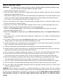
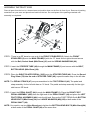
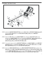
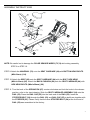
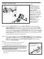
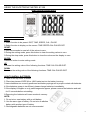
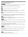
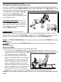
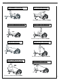
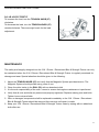
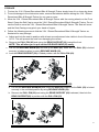
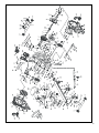
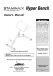
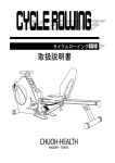
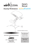
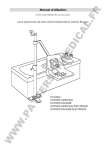
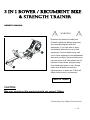
3 IN 1 ROWER / RECUMBENT BIKE
& STRENGTH TRAINER
OWNER’S MANUAL
WARNING
Exercise can present a health risk.
Consult a physician before beginning
any exercise program with this
equipment. If you feel faint or dizzy,
immediately discontinue use of this
equipment. Serious bodily injury can
occur if this equipment is not assembled
and used correctly. Serious bodily injury
can also occur if all instructions are not
followed. Keep others and pets away
from equipment when in use. Always
make sure all bolts and nuts are
tightened prior to each use. Follow all
safety instructions in this manual.
MADE IN TAIWAN
CAUTION:
Max user weight on this product should not exceed 125kgs.
Product May Vary Slightly From Pictured.
v. IV
SAFETY INSTRUCTIONS
WARNING:
To reduce the risk of serious injury, read the following Safety Instructions before using
the 3 IN 1 Rower / Recumbent Bike & Strength Trainer.
1. Read all warnings posted on this product.
2. Read this Owner’s Manual and follow it carefully before using this machine. Make sure that it is properly
assembled and tightened before use.
Keep children away from the 3 IN 1 Rower / Recumbent Bike & Strength Trainer. Do not allow children to use
or play on the 3 IN 1 Rower / Recumbent Bike & Strength Trainer. Keep children and pets away from the
3 IN 1 Rower / Recumbent Bike & Strength Trainer when it is in use.
4. Set up and operate the 3 IN 1 Rower / Recumbent Bike & Strength Trainer on a solid level surface. Do not
position on loose rugs or uneven surfaces.
5. Inspect the 3 IN 1 Rower / Recumbent Bike & Strength Trainer for worn or loose components prior to use.
6. Tighten / replace any loose or worn components prior to using this machine.
Make sure the Rear Support (62) is locked properly with the Pull Pin (63) before using 3 IN 1 Rower /
Recumbent Bike & Strength Trainer.
8. Make sure the Rail (52) is locked properly by the Release Knob (59) located on the Support Tube(56) when
in storage.
9. Keep fingers clear of all pinch points when folding and unfolding the 3 IN 1 Rower / Recumbent Bike &
Strength Trainer.
10. Lock seat in position with at least one adjustment hole visible in front of the seat before lifting rail to
storage position. This will prevent the seat from damaging the covers.
11. Consult a physician prior to commencing an exercise program. If, at any time during exercise, you feel faint,
dizzy, or experience pain, stop and consult your physician.
12. Follow your physician’s recommendations in developing your own personal fitness program.
13. Always choose the workout which best fits your physical strength and flexibility level. Know your limits and
train within them. Always use common sense when exercise.
14. Do not wear loose or dangling clothing while using this 3 IN 1 Rower / Recumbent Bike & Strength Trainer.
15. Never exercise in bare feet or socks; always wear correct footwear, such as running, walking, or
cross-training shoes. Be sure that they fit well, provide foot support and feature non-skid rubber soles.
16. Be careful to maintain your balance while using, mounting, dismounting, or assembling the 3 IN 1 Rower /
Recumbent Bike & Strength Trainer, loss of balance may result in a fall and serious bodily injury.
17. The 3 IN 1 Rower / Recumbent Bike & Strength Trainer should not be used by persons weighing over 125kgs.
18. The 3 IN 1 Rower / Recumbent Bike & Strength Trainer should be used by only one person at a time.
19. The 3 IN 1 Rower / Recumbent Bike & Strength Trainer is for domestic consumer use only. It is not for use in
public or semipublic facilities.
WARNING: Before starting any exercise or conditioning program you should consult with your personal
physician to see if you require a complete physical exam. This is especially important if you are over the age of
35, have never exercised before, are pregnant, or suffer from any illness. READ AND FOLLOW THE SAFETY
PRECAUTIONS. FAILURE TO FOLLOW THESE INSTRUCTIONS CAN RESULT IN SERIOUS BODILY
INJURY.
2
HAREWARE INDETIFICATION CHART
This chart is provided to help identify the hardware used in the assembly process. Place the washers, the end of the bolts,
or screws on the circles to check for the correct diameter. Use the small scale to check the length of the bolts and screws.
NOTICE: The length of all bolts and screws except those with flat heads is measured from
below the head to the end of the bolt or screw. Flat head bolts and screws
are measured from the top of the head to the end of the bolt or screw.
After unpacking the unit, open the hardware bag and make sure that you have all the following items. Some hardware
may be already attached to the part.
Part No. and Description
Qty
53 Stopper
1
54 Stopper Bolt
1
63 Pull Pin
1
78 Round Plug 25mm
2
79 Nut Cap (M10)
8
81 Bolt, Socket Head (M8x1.25x70mm)
2
89 spring washer
2
3
HAREWARE INDETIFICATION CHART
Part No. and Description
Qty
94 Bolt, Button Head (M8x 1.25x 15mm)
3
95 Bolt, Hex Head (M6x 1 x 15mm)
4
96 Bolt, Hex Head (M6x1x30mm)
4
97 Bolt, Hex Head (M8x1.25x16mm)
4
101 Bolt, Hex Head(M10x1.5x85mm)
1
102 Bolt, Hex Head(M10x1.5x95mm)
1
103 Bolt, Hex Head(M10x1.5x125mm)
1
105 Nylock Nut(M10x1.5)
3
109 Large Washer (M8xφ23)
2
114 Bolt, Button Head(M8x1.25x12mm)
4
4
ASSEMBLY INSTRUCTIONS
Place all parts form the box in a cleared area and position them on the floor in front of you. Remove all packing
materials from your area and place them back into the box. Do not dispose of the packing materials until
assembly is completed.
STEP 1: There is an “R” decal on one end of the FRONT STABILIZER (2). Attach the FRONT
STABILIZER (2) onto the MAIN FRAME(1) with the “R” decal end at right side and secure
with the Bolt, Socket Head (M8x70mm) (81) and the SPRING WASHER M8 (89).
STEP 2: Insert the STOPPER TUBE (48) through the MAIN FRAME (1) and secure with the BOLT,
BUTTON HEAD (M8x15mm) (94).
STEP3: Place the RIGHT PILATES PEDAL (116R) onto the STOPPER TUBE (48). Press the Round
Plug 25mm (78) into the end of STOPPER TUBE (48); repeat the same step in the left side.
NOTE: The PEDAL STRAPS (47) are pre-assembled to the FOOT PEDALS (46). The pedal and
strap assembly for the left side has an “L” decal. The pedal and strap assembly for the right
side has an “R” decal.
STEP 4: Insert the PEDAL SHAFT (44) through the MAIN FRAME (1). Place the RIGHT FOOT
PEDAL ASSEMBLY (46R) onto the right end of the PEDAL SHAFT (44) and place the LEFT
FOOT PEDAL ASSEMBLY (46L) onto the left end. Secure the FOOT PEDALS with BUTTON
HEAD BOLTS (M8x15mm) (94) and LARGE WASHERS (M8)(109) at both ends of the
PEDAL SHAFT (44).
NOTE: You need to use two Allen Wrenches to tighten the BUTTON HEAD BOLTS (M8x15mm)(94)
at both ends of the PEDAL SHAFT(44) at the same time.
5
ASSEMBLY INSTRUCTIONS
STEP 5: Attach the SUPPORT BRACKET (60) onto the RAIL (52) with HEX BOLTS (M8x16mm) (97).
Press the NUT CAPS (79) onto the NYLOCK NUT (M10) (105) and the HEX BOLT
(M10x75mm) (100).
STEP 6: Attach the RAIL (52) onto the MAIN FRAME (1) by sliding the RAIL PIVOT (49) into the
bracket on the MAIN FRAME (1) and securing with the HEX BOLT (M10x125mm) (103) and
the NYLOCK NUT (M10) (105). Press the NUT CAPS (79) onto the HEX BOLT
(M10x125mm) (103) and NYLOCK NUT (M10) (105).
STEP 7: Connect the lower end of the SUPPORT TUBE (56) to the MAIN FRAME (1) with HEX BOLT
(M10x85mm)(101) and NYLOCK NUT(M10)(105). Press the NUT CAPS (79) onto the HEX
BOLT (M10x85mm) (101) and the NYLOCK NUT (M10)(105).
STEP 8: Attach the REAR SUPPORT (62) into the REAR SUPPORT BRACKET (61) located on the
RAIL(52) with the BOLT, HEX HEAD (M10x95mm) (102) and the NYLOCK NUT (M10) (105).
Lock the REAR SUPPORT (62) in position with the PULL PIN (63). Press the NUT CAPS (79)
onto the BOLT, HEX HEAD (M10x95mm) (102) and the NULOCK NUT (M10) (105).
6
ASSEMBLY INSTRUCTIONS
NOTE: Be careful not to damage the PULSE SENSOR WIRES (73,74) while doing assembly
STEP 8 to STEP 10.
STEP 9: Attach the HANDRAIL (70) onto the SEAT CARRIAGE (64) with BUTTON HEAD BOLTS
(M8x12mm) (114).
STEP 10: Attach the SEAT (68) onto the SEAT CARRIAGE (64) with the BOLT, HEX HEAD
(M6x1x15mm) (95). Attach the BACK CUSHION (69) onto the SEAT CARRIAGE (64) with
HEX HEAD BOLTS (M6x1x30mm) (96).
STEP 11: Turn the knob of the SPRING PIN (67) counter-clockwise and lock the knob in the release
position, refer to the inset drawing. Slide the SEAT CARRIAGE ASSEMBLY (64) onto the
RAIL (52). Press the RAIL CAP (55) into the back end of the RAIL (52). Insert the
STOPPER BOLT (54) through the RAIL (52) and RAIL CAP (55) to bolt them together with
the STOPPER (53). Please verify that the other STOPPER BOLT (54) at the front end of
RAIL (52) was assembled at the factory.
7
ASSEMBLY INSTRUCTIONS
NOTE:
The RIGHT PEDAL (41)
has R decal stamped on
the end of the right pedal
shaft. The RIGHT
PEDAL (41) has right hand
threads and is tightened by
turning clockwise. The LEFT
PEDAL (39) has L decal
stamped on the end of the left
pedal shaft. The LEFT
PEDAL (39) has
left hand threads and is
tightened by turning
counter-clockwise.
STEP 12: Thread the RIGHT PEDAL (41) onto the RIGHT CRANK (37) located at inside of the
CRANK COVER (35) as the photo shown. Tighten the pedal securely. Select the RIGHT
PEDAL STRAP (42) which has R decal marked on the bottom side of the strap. Snap the
three hole end onto the inside edge of the RIGHT PEDAL (41). Snap the other end onto the
outside edge of the RIGHT PEDAL (41) with the R decal mark on the bottom of the RIGHT
PEDAL STRAP (42). Select adjustment holes which allow your foot to be easily removed
from the pedals. Do the same way on the left side.
STEP 13: Refer to the inset drawing. Plug the PULSE SENSOR WIRE (73) into the preset socket of
the PULSE COIL WIRE (74) located on the SEAT CARRIAGE (64). Plug the PULSE COIL
WIRE (74) into the preset socket of PULSE CONNECTION WIRE (75) located on the
bracket on the MAIN FRAME (1).
STEP 14:
a.
A bottle of silicone is packed together with user’s manual.
b. Gently apply the silicone to the rollers sliding path
(inner upper side and inner bottom side) on the aluminum rail.
Note: Apply liberally but be cautious not to spill the lubricant as
Lubricate the silicone to
the rollers sliding path on
the aluminum rail.
applied surfaces will become very slippery. To clean spills use
warm soapy water, repeat if necessary.
c. Then slowly slide the Seat forward and backward for a few seconds
allowing the lubricant spread evenly on the rollers sliding path on
aluminum rail.
8
USING THE ELCETRONIC METER- 81338
USING THE ELECTRONIC METER
KEY GUIDE:
MODE:
1.Select function to be preset. DIST, TIME, SPEED, CAL, PULSE.
2.Select function to display on the screen. TIME-SPEED-CAL-PULSE-DIST.
RESET:
1.Hold two seconds to reset all of the values to zero.
2.During the setting mode, press this button to clear the setting values to zero.
3.During the stop mode, press this button to clear the values on the display to zero.
ENTER:
Press this button to enter setting mode.
UP
Increase the setting value of the following functions: TIME-CAL-PULSE-DIST.
DOWN
Decrease the setting value of the following functions: TIME-CAL-PULSE-DIST.
HOW TO INSTALL BATTERIES:
1. Take off the top cover of meter.
2. Place two pieces of SIZE-AA or UM-3 batteries into the battery housing.
3.Insure batteries are correctly positioned and battery springs are in proper contact with batteries.
4.If the batteries power is insufficient, please change batteries immediately.
5.If the display is illegible or only partial segments appear, please remove the batteries and wait
for 15 seconds before reinstalling.
6.Removing the batteries will erase monitor's memory.
NOTE:
1. Do not mix a new battery with an old battery.
2. Use the same type of battery. Do not mix an alkaline
battery with another type of battery.
3. Rechargeable batteries are not recommended.
9
USING THE ELCETRONIC METER- 81338
FUNCTION AND OPERATION:
AUTO ON/OFF
The monitor will start up automatically if the exercise machine is in motion. If stop exercising for
over 4 minutes, monitor will turn off and reset all function values to zero.
KPH
The unit for the speed is kilometer per hour. The unit for distance is kilometer.
MPH
The unit for the speed is mile per hour. The unit for distance is mile.
SCAN
Press the MODE button until SCAN display on the screen. Automatically scans TIME-SPEED
-CAL-PULSE-DIST in sequence with a change every six seconds.
TIME
Press the MODE button until TIME display on the screen. Monitor will display the time values on
the screen.
Count up: Counts upward to 99:59 in one second increments once the meter is turned on.
Count down: Setting the exercise time from 0:00-99:00, the monitor will count down from preset
values. Once reach setting value, monitor will alarm.
SPEED
Press the MODE button until SPEED displays on the screen. Monitor will display the current
speed values from 0.0 to 99.9 km or mile on the screen.
CALORIE
Press MODE button until CAL display on the screen. Monitor will display the calorie consumption
values on the screen.
Count up: Without setting the calorie value, the monitor will count up the values from 0.0 to 999.9
kcal.
Count down: Setting the calorie value from 0.0 to 999.0 kcal, the monitor will count down from
preset values, Once reach setting value, monitor will alarm.
The calorie readout is an estimate for an average user. It should be used only as a comparison
between workouts on this unit.
DISTANCE
Press MODE button until DIST display on the screen. Monitor will display the distance values on
the screen.
Count up: Without setting the distance value, the monitor will count up the values from 0.0
to 999.9 km or mile.
Count down: Setting the distance values from 0.0 to 999.9 km or mile, the monitor will count
down from preset values. Once reach setting value, monitor will alarm.
PULSE
Press MODE button until display on the screen.
The monitor will display your current pulse rate in beats per minute.
10
USING THE ELCETRONIC METER- 81338
To display pulse, select the PULSE MODE and grasp the pulse sensors on the handrail, one
in each hand. The heart icon will flash when the meter senses your pulse. Your pulse will be
displayed approximately five seconds after the heart icon is displayed. If the heart icon does
not appear, relax your grip or change your grip on the pulse sensors.
If you preset the PULSE value, the meter will warn you with an audible alarm when your
pulse exceeds the set value. Stop exercising until your pulse comes down.
11
OPERATIONAL INSTRUCTIONS
RECUMBENT BIKE MODE AND ROWER MODE
Your 3 IN 1 Rower/Recumbent Bike & Strength Trainer can be used in the Recumbent Bike mode or
the Rower mode. When the SPRING PIN (67) locks the SEAT ASSEMBLY to the RAIL (52), the Rower,
Recumbent Bike & Strength Trainer is in the Recumbent Bike mode. When the SPRING PIN (67) is in
the Release position, the SEAT ASSEMBLY
is not locked to the RAIL (52) and the
Rower, Recumbent Bike & Strength Trainer
is in the Rower mode.
RECUMBENT BIKE MODE: Pull the knob
on the SPRING PIN (67), turn it clockwise
and release the knob to allow it to lock the
seat in position. Sit on the seat and pedal
with the PEDALS (39,41).
ROWER MODE: Pull the knob on the
SPRING PIN (67) and turn it counter-clockwise to lock it in the release position. Refer to the inset
drawing. This will allow the SEAT ASSEMBLY to slide freely on the RAIL (52). To workout, sit on the
seat, place your feet on the fixed FOOT PEDALS (46) and pull on the HANDLEBAR (25).
NOTE: If the FRONT STABILIZER(2) raises off the floor during use, adjust the STAND(43) to a higher
position.
CAUTION: Always verify that the SPRING PIN (67) is in the correct position before you begin your
workout.
SEAT ADJUSTMENT
Proper seat adjustment is important for Recumbent Bike mode.
1. Pull the knob on the SPRING PIN (67) and slide the SEAT ASSEMBLY forward or backward to
adjust the seat. Release the knob on the SPRING PIN (67) and make sure it is inserted into one of
the adjustment holes in the RAIL (52).
2. Sit on the seat and place your feet on the
pedals. You should be able to move through a
complete pedal stroke without locking your
knees or shifting your hips on the seat. The
seat is too close to the pedals if you have
more than a slight bend in your knees at the
bottom of the pedal stroke. The seat is too far
from the pedals if you have to completely
straighten your knees at the bottom of the pedal stroke. Refer to the illustrations below.
WARNING: Do not attempt to adjust the seat while you are on the 3 IN 1 Rower/Recumbent Bike & Strength
Trainer.
12
BODY MOVEMENT EXERCISE
RECUMBENT EXERCISE
BUTTOCKS EXERCISE
Be sure to step on the Steel PEDAL
LEG EXTENSION EXERCISE
LEG STRETCH EXERCISE
Be sure to step on the Steel PEDAL
ROWER EXERCISE
BICEPS CURL EXERCISE
Be sure to step on the Steel PEDAL
SINGLE ARM BICEP CURL
Be sure to step on the Steel PEDAL
ABDOMINAL EXERCISE
13
OPERATIONAL INSTRUCTIONS
LOAD ADJUSTMENT
To increase the load, turn the TENSION KNOB (27)
clockwise.
To decrease the load, turn the TENSION KNOB (27)
counterclockwise. There are eight levels for the load
adjustment.
MAINTENANCE
The safety and integrity designed into the 3 IN 1 Rower / Recumbent Bike & Strength Trainer can only
be maintained when the 3 IN 1 Rower / Recumbent Bike & Strength Trainer is regularly examined for
damage and wear. Special attention should be given to the following:
1. Adjust the TENSION KNOB (27) and verify that the Magnetic System provides tension. The
Magnetic System should provide many years of use.
2. Clean the roller tracks in the RAIL (52) with an absorbent cloth.
3. It is the sole responsibility of the user / owner to ensure that regular maintenance is performed.
4. Verify that all nuts and bolts are present and properly tightened. Replace missing nuts and bolts.
Tighten loose nuts and bolts.
5. Worn or damaged components shall be replaced immediately or the 3 IN 1 Rower / Recumbent
Bike & Strength Trainer should be removed from service until repair is made.
6. Keep your 3 IN 1 Rower / Recumbent Bike & Strength Trainer clean by wiping with an absorbent
cloth after use.
14
STORAGE
1. To store the 3 IN 1 Rower/Recumbent Bike & Strength Trainer simply keep it in a clean dry place.
2. To avoid damage to the electronics meter, remove the batteries before storing the 3 IN 1 Rower/
Recumbent Bike & Strength Trainer for one year or more.
3. Move the 3 IN 1 Rower/Recumbent Bike & Strength Trainer with the moving wheels on the Front
Stand. Grasp the Rail Cap to move the 3 IN 1 Rower/Recumbent Bike & Strength Trainer. Do not
use the Seat to move the 3 IN 1 Rower/Recumbent Bike & Strength Trainer. The Seat will move
and the Seat Carriage may pinch your hand or fingers.
4. Follow the following process to fold the 3 IN 1 Rower/Recumbent Bike & Strength Trainer as
illustrated for easy storage.
a. Adjust and lock the seat in position with at least one adjustment hole visible in front of the seat.
NOTE: This will prevent the seat from damaging the covers.
b. Remove the PULL PIN (63) and swing the REAR SUPPORT (62) toward the front.
NOTE: This will allow you to pull out the RELEASE KNOB (59) easily.
c. Pull out the RELEASE KNOB (59) and fold up the RAIL (52). Make sure the RAIL (52) is locked
securely in folded position by using RELEASE KNOB (59).
d. Lock the REAR SUPPORT (62) in folded position with the PULL PIN (63).
A
C
D
B
UNFOLD THE ROWER, RECUMBENT BIKE & STRENGTH TRAINER
a. Pull out the RELEASE KNOB(59) and unfold the RAIL(52). Make sure the RAIL (52) is locked
securely in the unfolded position by using RELEASE KNOB (59).
b. Remove the PULL PIN (63) and swing the REAR SUPPORT (62) backward, then lock the
REAR SUPPORT(62) in position with the PULL PIN (63).
A
B
15
TROUBLE SHOOTING
Symptom
The LCD Screen does
Possible Cause
Solution
You have the wrong Adaptor or the
Check that the Batteries or the Adaptor Specifications
wrong Batteries?
coincide With Instruction Manual Specifications.
The Mains Power switch is turned
Check that the Mains Power is switched on and is indeed
off?
supplying Power.
The Adaptor is not plugged in?
Check that the Adaptor is correctly connected to the Mains
NOT Display anything.
Power Socket and is correctly connected to the Computer.
The Batteries are missing?
Check to make sure there and Batteries installed.
The Batteries are inserted the
Check that the Batteries are inserted the correct way around
wrong way around?
and that they are in the correct series (i.e.-+)
The Computer is faulty.
Replace the Computer by contacting your dealer.
1)Check that the Sensor Magnet is correctly fitted and passes
in front of the Sensor.
2)Check the gap between Speed Sensor and the Magnet is
The Screen is faulty.
The Speed Display
correct 5mm or less.
The Computer is faulty.
3)Check that all the Computer Plugs and Sockets are FIRMLY
shows 0.
and correctly connected.
4)Check that the Computer Wires are not damaged.
The Computer isn't receiving a
If all these Checks fail, then replace the Sensor.
signal from the Speed Sensor?
Replace the Computer by contacting your dealer.
The connection between the Circuit
Check that the Circuit Board is securely fastened to the
Board and the LCD Screen
Computer Case, retighten the Screw. Take care NOT to over
Membrane is loose, gently press
tighten them as this may destroy the Circuit Board. Firm is
down on the LCD Screen, if the
good when you meet resistance STOP.
LCD Screen Partial Display
disappears then it is a connection
The LCD Screen Partially
problem.
Displays.
The connection between the Circuit
Open the Computer Case, remove the Circuit Board Screws,
Board and the LCD Screen
gently remove the Circuit Board, realign the LCD Screen
Membrane is misaligned. If this is
and/or the Membrane, reassemble the LCD Screen and/or the
the problem you might be able to
Membrane taking care not to bump or knock the Membrane
see that the LCD Screen is on a
out of alignment before the Circuit Board Screws are tight.
slight angle and NOT inline or
Reinsert the Circuit Board Screws and tighten them taking
parallel with the Computer Case.
care NOT to over tighten them as this may destroy the Circuit
Board. Firm is good when you meet resistance STOP.
The Computer is faulty
Replace the Computer by contacting your dealer.
16
TROUBLE SHOOTING
Symptom
Possible Cause
Solution
The Computer is NOT receiving
Check that the Ear Clip Plug is FIRMLY inserted into
a Pulse Signal.
the Computer.
1) The Ear Clip Pulse Sensors will NOT operate
correctly if your skin is extremely dry, dab a little water
No Ear Pulse Signal or
incorrect Ear Pulse Signal.
The Computer is receiving a
onto your earlobe and try again
2) Check that the Ear Clip is firmly connected to your
faint Pulse Signal.
earlobe.
3) Clean the Ear Clip Sensor Pads to ensure a good
contact between your body and the Sensor Pads.
The Ear Clip is faulty.
After completing all of the above Checks, if the problem
still exists then replace the Ear Clip by contacting your
dealer.
The Computer is faulty.
Replace the Computer by contacting your dealer.
The Computer is NOT receiving
Check that the Hand Pulse Plugs are FIRMLY inserted
a Pulse Signal.
into the Sockets.
(1)The Hand Pulse Sensors will NOT operate correctly
if your skin is extremely dry moisten your hands with a
little water and try again.
2) The Hand Pulse Sensors are designed to be held
firmly, if you move your hands while exercising then the
No Hand Pulse Signal or
Incorrect
Signal.
Hand
Pulse
The Computer is receiving a
Computer may receive an intermittent Pulse Signal.
faint
Avoid moving your hands while exercising and hold the
of
Intermittent
Signal.
Pulse
Hand Pulse Sensors firmly while exercising. If you do
move your hands while exercising give the Computer a
few seconds to resample and display your correct Pulse
Heart Rate.
3)Clean the Hand Pulse Sensors to ensure a good
contact between your body and the Pulse Sensors.
4)Remove the Hand Pulse Sensors in order to check
that the Spade Terminals are correctly attached.
The Computer is faulty.
After completing all of the above Checks, if the problem
still exists then please contact your dealer.
Replace the Computer by contacting your dealer.
17
CONDITIONING GUIDELINES
How you begin your exercise program depends on your physical condition. If you have been inactive
for several years, or are severely overweight, you must slowly and increase your time on the 3 IN 1
Rower/Recumbent Bike & Strength Trainer gradually: a few minutes per workout.
Initially, you may be able to exercise only for a few minutes in your target zone, however, your aerobic
fitness will improve over the next six to eight weeks. Don’t be discouraged if it takes longer. It’s
important to work at your own pace. Ultimately, you’ll be able to exercise continuously for 30 minutes.
The better your aerobic fitness, the harder you will have to work to stay in your target zone. Please
remember these essentials:
․ Have your doctor review your training and diet programs to advise you of a workout routine you
should adopt.
․ Begin your training program slowly with realistic goals that have been set by you and your doctor.
․ Monitor your pulse frequently. Establish your target heart rate base on your age and condition.
․ Set up your 3 IN 1 Rower/Recumbent Bike & Strength Trainer on a flat, even surface at least 3 feet
from walls and furniture.
EXERCISE INTENSITY
To maximize the benefits of exercising, it is important to exercise with the proper intensity. The proper
intensity level can be found by using your heart rate as a guide. For effective aerobic exercise, your
heart rate should be maintained at a level between 70% and 85% of your maximum heart rate as you
exercise. This is known as your target zone. You can find your target zone in the table below. Target
zones are listed for both unconditioned and conditioned persons according to age.
During the first few months of your exercise program, keep your
heart rate near the low end of your target zone as you exercise.
After a few months, your heart rate can be increased gradually
until it is near the middle of your target zone as you exercise.
To measure your heart rate manually,
stop exercising but continue moving
your legs or walking around and place
two fingers on your wrist. Take a
six-second heartbeat count and
multiply the results by 10 to find your
heart rate. For example, if your six-second heartbeat count is 14,
your heart rate is 140 beats per minute. (A six-second count is
used because your heart rate will drop rapidly when you stop
exercising.) Adjust the intensity of your exercise until your heart
rate is at the proper level.
18
WARM-UP and COOL-DOWN
Warm-up The purpose of warming up is to prepare your body for exercise and to minimize injuries.
Warm up for two to five minutes before strength-training or aerobic exercising. Perform activities that
raise your heart rate and warm the working muscles. Activities may include brisk walking, jogging,
jumping jacks, jump rope, and running in place.
Stretching Stretching while your muscles are warm after a proper warm-up and again after your
strength or aerobic training session is very important. Muscles stretch more easily at these times
because of their elevated temperature, which greatly reduces the risk of injury. Stretches should be held
for 15 to 30 seconds. Do not bounce.
Suggested Stretching Exercises
Lower Body Stretch
Place feet shoulder-width
apart and lean forward. Keep
this position for 30 seconds
using the body as a natural
weight to stretch the backs of
the legs.
DO NOT BOUNCE!
When the pull on the back of
the legs lessen, try a lower
position gradually.
h
Floor Stretch
While sitting on the floor, open
the legs as wide as possible.
Stretch the upper body toward
the knee on the right leg by
using your arms to pull your
chest to your thighs. Hold this
stretch 10 to 30 seconds.
DO NOT BOUNCE!
Do this stretch 10 times.
Repeat the stretch with the left
leg.
Bent Torso Pulls
While sitting on the floor,
have legs apart one leg
straight and one knee bent.
Pull the chest down to touch
the thigh on the leg that is
bent and twist at the waist.
Hold this position at least 10
seconds. Repeat 10 times
on each side.
Bent Over Leg Stretch
Stand with feet shoulder-width
apart and lean forward as
illustrated. Using the arms,
gently pull the upper body
towards the right leg. Let the
head hand down. DO NOT
BOUNCE! Hold the position a
minimum of 10 seconds.
Repeat pulling the upper body
to the left leg. Do this stretch
several times slowly.
Remember always to check with your physician before starting any exercise program.
Cool-Down The purpose of cooling down is to return the body to its normal, or near normal, resting state
at the end of each exercise session. A proper cool-down lowers your heart rate and allows blood to
return to the heart. Your cool-down should include the stretches listed above and should be completed
after each strength-training session.
19
20
PARTS LIST
NO.
PART NAME
QTY
NO.
PART NAME
QTY
1
Main Frame
1
37
Right Crank
1
2
Front Stabilizer
1
38
Flange Bolt (M8x1.25x25mm)
3
3
Axle
1
39
Left Pedal
1
4
Pulley
1
40
Left Pedal Strap
1
5
Strap Wheel
1
41
Right Pedal
1
6
Connection Wheel
1
42
Right Pedal Strap
1
7
One Way Bearing(3520)
2
43
Stand
1
8
Bearing (6004zz)
4
44
Pedal Shaft
1
9
C Ring (M20)
2
45
Spacer
2
10
Bearing Housing
2
46
Foot Pedal
2
11
V-Ribbed Belt
1
47
Pedal Strap
2
12
Idler Arm
1
48
Stopper Tube
1
13
Idler Wheel
1
49
Rail Pivot
1
14
Idler Wheel Spacer
1
50
Pivot Bushing
2
15
Tension Spring
1
51
Rail Connection Cap
1
16
Magnetic System
1
52
Rail
1
17
Bungee Cord
1
53
Stopper
2
18
Bungee Wheel
3
54
Stopper Bolt
2
19
Wheel Bushing
3
55
Rail Cap
1
20
Wheel Spacer
3
56
Support Tube
1
21
Strap
1
57
Inner Support Tube
1
22
Strap Roller
2
58
Bushing
1
23
Roller Axle
1
59
Release Knob
1
24
Roller Spacer
2
60
Support Bracket
1
25
Handlebar
1
61
Rear Support Bracket
1
26
Foam Grip
2
62
Rear Support
1
27
Tension Knob
1
63
Pull Pin
1
28
Magnet
1
64
Seat Carriage
1
29
Sensor Wire
1
65
Seat Roller
4
30
Top Meter Cover
1
66
Seat Roller Spacer (φ8xφ12x6.5mm)
4
31
Top Cover
1
67
Spring Pin
1
32
Meter
1
68
Seat
1
33
Left Cover
1
69
Back Cushion
1
34
Right Cover
1
70
Handrail
1
35
Crank Cover
2
71
Foam Grip
2
36
Left Crank
1
72
Pulse Sensor Plate
2
21
NO.
PART NAME
QTY
NO.
PART NAME
QTY
73
Pulse Sensor Wire
1
110
Washer (M10)
2
74
Pulse Coil Wire
1
111
One way Bearing(2520)
1
75
Pulse Connection Wire
1
113
Roller Spacer
1
76
Moving Wheel
2
114
Bolt, Button Head (M8x12mm)
4
77
Round Endcap (60mm)
4
115
Bolt, Round Head (M5x12mm)
4
78
Round Plug (25mm)
4
116
Pilates Pedal
2
79
Nut Cap (M10)
8
117
Plug
2
80
Carriage Bolt (M8x1.25x60mm)
3
118
Bolt, Hex Head(M8x1.25x70mm)
1
81
Bolt, Socket Head (M8x1.25x70mm)
2
119
Washer (φ26xφ38 x 2.0t)
2
82
Screw, Round Head (M4x20mm)
7
120 Washer (φ6xφ32 x 2.0t)
1
83
Screw, Round Head (M4x25mm)
2
121 Washer (φ26xφ34x 1.0t)
1
84
Screw, Round Head (M5x18mm)
8
122 Square Plug
1
85
Screw, Round Head (M5x0.8x15mm)
1
123 Bolt, Hex Head (M10x1.5x65mm)
1
86
Nylock Nut (M8x1.25x6.2t)
4
124 Nylock Nut (M10×1.5)
1
87
Bolt, Socket Head (M5x0.8x15mm)
7
125 Bearing 6804
1
88
Bolt, Round Head (M6x1x15mm)
4
89
Spring Washer (M8)
6
90
Bolt, Flat Head (M8x1.25x16mm)
4
91
Bolt, Flat Head (M8x1.25x25mm)
1
92
Bolt, Flat Button Head (M8x1.25x25mm)
4
93
Bolt, Button Head (M6x1.0x12mm)
2
94
Bolt, Button Head (M8x1.25x15mm)
3
95
Bolt, Hex Head (M6x1x15mm)
4
96
Bolt, Hex Head (M6x1x30mm)
4
97
Bolt, Hex Head (M8x1.25x16mm)
8
98
Bolt, Hex Head (M8x1.25x55mm)
4
99
Bolt, Hex Head (M10x1.5x45mm)
1
100 Bolt, Hex Head (M10x1.5x75mm)
1
101 Bolt, Hex Head (M10x1.5x85mm)
1
102 Bolt, Hex Head (M10x1.5x95mm)
1
103 Bolt, Hex Head (M10x1.5x125mm)
1
104 Nylock Nut (M8x1.25x8t)
4
105 Nylock Nut (M10x1.5)
5
106 Flange Nut (M10x1.25)
2
107 Washer (M6)
2
108 Washer (M8xφ16)
5
109 Large Washer (M8xφ23)
2
22
WARRANTY, SAFETY AND ASSEMBLY INFORMATION
BFE0039 – 3 IN 1 ROWER / RECUMBENT & STRENGTH TRAINER
IMPORTANT
Please read and retain this manual as it will assist with identification for parts and service.
-----------------------------------------------------------------------------------------------------------BOYLES FITNESS warrants their products to be free from defects in material and workmanship under
normal use and service conditions.
The various components of this machine are warranted against defects and workmanship for the time
periods specified as follows:
BFE0039
3 IN 1 ROWER / RECUMBENT &STRENGTH TRAINER
LIMITED WARRANTY
Lifetime Frame
12 months Parts
All warranty coverage extends only to the original retail purchaser from the date of purchase. BOYLES
FITNESS’ obligation under this Warranty is limited to replacing or repairing, at BOYLES’ option, the
product or parts therein. Any enquiries relating to warranties or spare parts must be directed to
Service 07 3272 7010.
For efficient processing of your enquiry please have relevant date of purchase, retailer name you
purchased the item from and the brand on the product. This warranty does not extend to any damage to
a product caused by abuse, improper or abnormal usage (as detailed in this instruction manual), or
repairs not provided by BOYLES. Nor does this warranty extend to products used for commercial or
rental purposes. This warranty does not cover ordinary wear, tear and weathering, failure to follow
directions, improper installation, improper maintenance or acts of God (such as damage caused by
storms, lightning and by snow or ice). No other Warranty beyond that specifically set forth above is
authorised by BOYLES.
21
Our sales and service centre has been set up to provide assembly assistance, replacement parts and
accessories, and to efficiently handle all warranty related matters.
Phone 07 3272 7010
Hours 9:00am – 4:00pm Mon-Fri (excluding public holidays)
Email: [email protected]
Website www.bfe.net.au
BFE Warranty Policy – November 1st 2013
1. When purchased from an authorised BFE distributor the BFE warranty shall guarantee that all
framework and components of your product are free from faulty manufacture. All faulty framework and
components will be repaired or replaced as set out in this policy. All warranties in this policy apply to INDOOR
HOME/DOMESTIC USE ONLY.
2. These warranties do not apply to products used in commercial use applications.
3. Warranty DOES NOT cover normal wear & tear and excludes faults due to misuse, abuse, incorrect assembly
or lack of general maintenance.
4. Warranty is applicable to products sold and placed within Australia only.
5. IMPORTANT. Most of BFE products are pretested and we have inspectors checking all products prior to
shipment. The number one reason for a fault is due to INCORRECT ASSEMBLY.
If you do have problems please go back to the start and double check your assembly and pay special attention to
all WIRING connections. If you have accidently cut or damaged the wiring please let us know and we will be happy
to send you a new set at no-charge.
If you have done this and are confident you have double checked your assembly and are still having problems
please email our service department at [email protected] including your best contact details ,proof of
purchase, serial number and a brief explanation of what is wrong. Emailing is the quickest and most reliable way
to get your service request processed. Once we have your details we will either call or email you back with the
next steps. The quickest way, once we determine the problem and send you a replacement part, is that we can talk
you through over the phone on how to fit it.
If it is deemed by our service tech that it is too difficult, we can arrange (where available) a service technician.
NOTE. If we arrange for a service technician (where applicable) and it is found that it is not a
Manufactures fault and found to be an assembly issue, normal wear and tear, transport damage or misuse then
there will be a call out fee of $140 depending on location. (Surcharge applies for non-metro areas)
WARRANTY TERMS- Warranty commences from the date of purchase from the retail store. Warranty only
applies to the original purchaser and is NON transferable. Warranty is void if the serial number of the product has
been removed or tampered with.
Warranty does not apply to defects, faults or failures due to:
(a) Defects caused during assembly or failure to assemble to the assembly manual provided. Assembly errors
include but are not limited to damaged wiring harness, stripped crank arms and or pedals and bolts used in the
wrong locations.
(b) Lack of general maintenance and or failure to service or maintain the equipment in accordance with the user
manual specifications and recommendations. This includes a lack of lubrication. Only use factory supplied
lubricant. DO NOT USE WD40 or anything simular. You can purchase lubricant from your retailer or contact us
directly at [email protected]
22
(c) Power Surges. The computers, control boards and motors are very sensitive to power fluctuations. You must
use a surge protector on all items that plug into your mains power otherwise your electronics will not be covered
by this warranty. You can purchase these from numerous retailers or you can call us on 02 46 366 680 to get a
price.
(d) User negligence, abnormal or excessive use, misuse, abuse or transport damage.
(e) Repairs, alterations or modifications by NON BFE authorised service technician.
(f) Accident, fire, flood or malicious damage by third person.
(g) Ordinary wear and tear.
(h) Failure to keep the product in a clean, dry environment causing rust. You should wipe off any sweat and
moisture after each training session.
(i) Any products sold or placed in an application or the incorrect environment that is not recommended by BFE or
as not stipulated in the owner’s manual such as a commercial / rental environment will void the warranty set forth
by BFE
(j) BFE recommends the use of a protective rubber floor mat. This reduces the incidence of dust and lint collection
around the motor, reduces noise & protects your floor. You can purchase this from your retailer or contact BFE
directly on 02 46 366 680
BFE will have the option to repair or replace any product which requires attention under the warranty.
NOTE: Lifetime refers to the warranty coverage of the units expected service life. NOT the lifetime of the
purchaser.
Servicing/Spare PartsAs with any mechanical equipment general maintenance should be performed on a regular basis by an authorised
retailer or service technician. This will ensure longevity of the product and ensure that it is kept working in optimum
condition. Failure to properly maintain your equipment may lead to safety issues and may also void the warranty.
You should only use genuine BFE replacement parts otherwise the warranty will be void.
Freight Costs:
The cost of freighting the replacement part under warranty to the customer shall be free of charge. Your
requirement is to return the faulty part via the pre-paid postal service which we will supply.
Returned Goods:
The unauthorised return of parts or product shall be refused and placed in the hands of the carrier at the cost of
the shipper. Return authorisations can be obtained from BFE head office only.
Additional Warranty
If you would like to extend your labour warranty by 1 year ($99), 2 years ($199), 3 years ($299) please contact our
office by emailing [email protected] (Not available in all areas)
Service Department hours: Monday to Friday between 9am and 4pm
Service Phone Number: 07 3272 7010 Email: [email protected]
23
PLEASE NOTE: that Authorised service technicians do not reside in all areas of this vast country. If you live
beyond the reasonable service area of a metropolitan area, BFE may not be able to support the labour portion of
the product warranty. Alternatively you can return (at your cost) your product to the closest BFE repair centre,
where it will be fixed at no charge under the warranty period.
Metropolitan Area- defined as no more that 50km from G.P.O in all capital cities.
Disclaimer:
Our goods come with guarantees that cannot be excluded under the Australian Consumer Law. You are entitled to
a replacement or refund for a ‘Major failure’ and for compensation for any other Reasonable foreseeable loss or
damage.
You are also entitled to have goods repaired or replaced if the goods fail to be of an acceptable quality and the
failure does not amount to a major failure.
BFE does not assume , nor authorise any representative or other person to make or assume for BFE, any
warranties whatsoever, whether expressed or implied, in , in connection with the sale, service, or shipment of our
products.
BFE reserve the right to make changes and improvements in our products and specifications without incurring any
obligation to similarly alter products previously purchased.
This warranty operates in addition to other rights and remedies available to consumer’s rights under the Australian
Consumer Law.
Service Department hours: Monday to Friday between 9am and 4pm
Service Phone Number: 07 3272 7010 Email: [email protected]
24