1
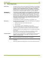
Electricity Meters IEC/MID
Residential
ZxF100Ax/Cx
E350 series 2
User Manual
Date: 20.12.2011
File name: D000027979 E350 ZxF100Ax Cx series 2 User Manual EN.docx
© Landis+Gyr
D000027979 EN n
2/54
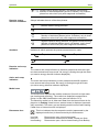
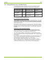
Revision History
Revision History
Version
Date
Comments
a
24.07.2009
First edition
b
18.01.2010
Example absolute value summation corrected, channel configuration table updated
with OBIS codes and remarks, instantaneous power accuracy added, new section
2.4 "Radio Interference", description of power up display corrected, range of CDS
and NDS display durations corrected, description of error display changed, meter
display list updated (without display text), description of optical interface enhanced,
description of manufacturer specific mode C-C added, description of optical test
outputs enhanced, minor formatting and text improvements.
c
05.05.2010
New display list items, Combined sum integrated in channel configuration (section
1.6); Summation modes updated, SW-version presentation updated, Disconnector
tamper added, More detailed explanation of disconnector icon, table of required
measuring times updated, display status messages added, error and status code
explanation extended, addressability added, advice (restriction) for SW-version <=
M23 added, Availability for disconnector added
d
24.08.2010
"Meter display list" corrected (voltage, current, frequency, power items);
Explanation efficiency registers updated; Table Instantaneous Values updated;
Display status messages updated; Meter tools added
e, f
06.09.2010
Minor formatting and text improvements
g
16.10.2010
Updating 1.8. Instantaneous values
h
09.12.2010
Section 5.2.5 Display sequence entirely updated (main and service display).
Declaration of conformity replaced.
k
17.03.2011
Note about restrictions for meters with software versions M21 to M23 added in
section 1.2 "Purpose of use". Section 1.3 "Advice" deleted (integrated into note in
section 1.2).
m
01.06.2011
Section 1.4 "Characteristic" expanded with remark about ZFF100 meters phase fail
behaviour; Section 2.3 "Safety Instructions" expanded with remark, that PE must
not be switched with disconnector and only "useful" tool have to be used; Section
5.2.7 "Error Display" modified; Remark about module data added in section 5.2.9;
Content of section 5.2.12 "Error descriptions E350 Series 1 and Series 2" moved
partly into functional description and partly to section 6.2 "Error Codes": Safety
information about cleaning added in section 6.1 and modified in section 7.2.;
Terminology changes: breaker disconnector, baud rate transmission rate,
baud bps (bits per second); Minor formatting and text improvements.
n
20.12.2011
Section 1.6.3: Adapted to software version M25 (8 measurement channels)
Section 5.2.9: New display item: Disconnector tamper counter.
Nothing in this document shall be construed as a representation or guarantee in respect of the performance, quality or durability of the
specified product. Landis+Gyr accepts no liability whatsoever in respect of the specified product under or in relation to this document.
Subject to change without notice.
© Landis+Gyr
D000027979 EN n – E350 series 2 ZxF100Ax/Cx – User Manual
Table of Contents
3/54
Table of Contents
Revision History ..................................................................................................................................... 2
Table of Contents ................................................................................................................................... 3
Introduction ............................................................................................................................................ 5
1
Description of Unit ....................................................................................................................... 6
1.1 General View ............................................................................................................................ 6
1.2 Purpose of Use ......................................................................................................................... 6
1.3 Field of Application.................................................................................................................... 7
1.4 Characteristics .......................................................................................................................... 8
1.5 Type Designation ...................................................................................................................... 9
1.6 Measuring Principle ................................................................................................................ 10
1.6.1 Overview ........................................................................................................................... 10
1.6.2 Signal Generation .............................................................................................................. 10
1.6.3 Signal Processing .............................................................................................................. 10
1.7 Instantaneous Values ............................................................................................................. 15
1.8 Anti-Tampering and Tamper Prevention ................................................................................. 15
1.9 Disconnector ........................................................................................................................... 16
1.10 Software Tools ........................................................................................................................ 16
2
Safety ........................................................................................................................................... 17
2.1 Safety Information ................................................................................................................... 17
2.2 Responsibilities ....................................................................................................................... 17
2.3 Safety Instructions .................................................................................................................. 18
2.4 Radio Interference .................................................................................................................. 18
3
Mechanical Description ............................................................................................................. 19
3.1 Housing ................................................................................................................................... 19
3.2 Face Plate ............................................................................................................................... 20
3.3 Connection Diagrams (examples) ........................................................................................... 20
3.4 Dimensions ............................................................................................................................. 21
4
Installation/De-installation ......................................................................................................... 23
4.1 Mounting the Meter ................................................................................................................. 23
4.2 Connecting the Meter .............................................................................................................. 24
4.3 Checking the Connections ...................................................................................................... 25
4.4 Commissioning and Functional Check .................................................................................... 25
4.5 Disconnecting the Meter ......................................................................................................... 26
5
Operation..................................................................................................................................... 27
5.1 Control Elements .................................................................................................................... 27
5.1.1 Display Button ................................................................................................................... 27
5.1.2 Disconnector Button .......................................................................................................... 27
5.2 Liquid Crystal Display (LCD) ................................................................................................... 28
5.2.1 Basic Layout ...................................................................................................................... 28
5.2.2 Explanation of LCD Elements............................................................................................ 28
5.2.3 Displaying OBIS Codes ..................................................................................................... 30
5.2.4 Display Definitions ............................................................................................................. 31
5.2.5 Display Sequence ............................................................................................................. 32
5.2.6 Display Check ................................................................................................................... 35
5.2.7 Error Display ...................................................................................................................... 35
5.2.8 Text Messages on Display ................................................................................................ 36
5.2.9 Meter Display List – Available Items with OBIS Codes ..................................................... 36
5.2.10 Display Status Messages .................................................................................................. 38
D000027979 EN n – E350 series 2 ZxF100Ax/Cx – User Manual
© Landis+Gyr
4/54
Table of Contents
5.2.11 Energy Efficiency Items in the Meter Display .....................................................................39
5.3 Optical Test Outputs ................................................................................................................40
5.4 Optical Interface ......................................................................................................................40
5.5 Data Readout ..........................................................................................................................41
5.5.1 IEC 62056-21 Mode C .......................................................................................................41
5.5.2 Readout Configuration .......................................................................................................41
5.5.3 Readout Status Code (C.5.0) .............................................................................................42
5.5.4 Data Readout Procedure via Optical Interface or AMR Module.........................................43
5.5.5 Addressability of Meter.......................................................................................................44
6
Service .........................................................................................................................................45
6.1 Operating Faults ......................................................................................................................45
6.2 Error Codes .............................................................................................................................45
6.2.1 Structure of an Error Code .................................................................................................45
6.2.2 Error Code Descriptions .....................................................................................................46
6.3 Repairing Meters .....................................................................................................................47
7
Maintenance ................................................................................................................................48
7.1 Meter Testing ...........................................................................................................................48
7.1.1 Higher Register Resolution ................................................................................................48
7.1.2 Measuring Times................................................................................................................49
7.1.3 Optical Test Outputs ..........................................................................................................49
7.1.4 Connection to a Meter Testing Device ...............................................................................50
7.1.5 Creep Test .........................................................................................................................51
7.1.6 Starting Test .......................................................................................................................51
7.2 Cleaning ..................................................................................................................................51
8
Decommissioning, Disposal ......................................................................................................52
8.1 Decommissioning ....................................................................................................................52
8.2 Disposal ...................................................................................................................................52
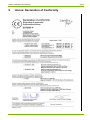
9
Annex: Declaration of Conformity .............................................................................................53
© Landis+Gyr
D000027979 EN n – E350 series 2 ZxF100Ax/Cx – User Manual
Description of Unit
5/54
Introduction
Range of validity
The present manual applies to the following E350 series 2 meter versions:
Three-phase four-wire network
ZMF100AC and ZMF100AB for active energy (import and export)
ZMF100CC and ZMF100CB for active and reactive energy (import and
export)
Three-phase three-wire network
ZFF100AC and ZFF100AB for active energy (import and export)
ZFF100CC and ZFF100CB for active and reactive energy (import and
export).
For a detailed explanation of the type designation see section 1.5.
Purpose
The user manual contains all information required for meter applications for
the intended purpose. This includes:
Provision of knowledge concerning characteristics, construction and
knowledge of meters
Information regarding possible dangers, their consequences and
measures to prevent any danger
Details concerning the performance of all work throughout the service
life of the meters (parameterisation, installation, commissioning, operation, maintenance, shutting down and disposal)
Target group
The content of this user manual is intended for technically qualified personnel of energy supply companies, responsible for system planning, installation and commissioning, operation, maintenance, decommissioning and
disposal of meters.
Reference documents
The technical data and functional description of the meters can be found in
separate documents:
D000027981 "Technical Data ZxF100Ax/Cx series 2"
D000028645 "Functional Description ZxF100Ax/Cx series 2"
D000027979 EN n – E350 series 2 ZxF100Ax/Cx – User Manual
© Landis+Gyr
6/54
Description of Unit
1
Description of Unit
1.1
General View
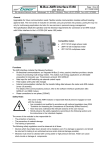
Fig. 1.1 General view of meter (with GSM/GPRS Module)
1.2
Purpose of Use
Restrictions for meters with software versions M21 to M23:
The meters may not be used in networks with significant disturbances in
the frequency range of 2 kHz to 150 kHz since the intended operating conditions of the meters according to the harmonised standards EN50470-1
and EN50470-3 assume no significant noise currents and voltages in this
frequency range.
Such significant disturbances occur for instance in large photovoltaic systems (influence of the inverters with high emissions of extreme harmonics)
and can cause additional errors in the meters, even though the meters
meet all applicable standards and directions.
The ZMF100 meters record active and reactive energy consumption in all
3-phase 4-wire networks. They are directly installed in the supply line by
the energy supply company and are read regularly for billing purposes.
The ZFF100 meters differ from ZMF meters in the type of measurement
(Aron circuit for three-phase three-wire networks). Therefore, they are only
equipped with 2 instead of 3 measuring elements.
The data is displayed on an LCD and is also available via optical interface
and with an AMR Module via CS, PLC modem, GSM/GPRS modem or
Ethernet. When provided with transmission contacts, the meters can also
be used as transmission contact meters for telemetering. The rates can be
controlled internally or externally with control inputs (on the AMR Module).
With an AMR module, the meters can also be used to record counting
pulses of other physical media (e. g. water or gas volumes) or to directly
transmit values recorded by other measuring devices.
Any other application of these meters is regarded as abuse.
© Landis+Gyr
D000027979 EN n – E350 series 2 ZxF100Ax/Cx – User Manual
Description of Unit
1.3
7/54
Field of Application
Basic series
The basic version provides energy registers for tariffication, red test diodes
for active and reactive energy, an optical interface for meter reading and an
interface for various communication forms. This interface is protected
against fraud and is independent of the module suppliers. The exchangeable AMR Module is situated outside the calibration liability. The functionality of this meter is suitable for smaller consumers, e.g. for households.
Disconnector
(ZxF100xB only)
The function of the disconnector is customer specific and is defined by the
communication module. Possible uses: anti-tampering (e.g. disconnection
in case of tampering with magnets), load limitation (fuse control), remote
disconnect (e.g. in case of change of tenant), prepayment. The status of
the disconnector is displayed on the meter, but the disconnector is controlled by the communication module. If you need detailed information on the
functionality of your disconnector, please consult the user manual of the
communication module installed.
The disconnector is available for connection on 3x 230/400 V only.
The basic series can be extended with various AMR Modules for additional
functions and communications:
Extensions
Multirate import/export with external rate control
S0 pulse output
Communication via PLC, GSM/GPRS, or other media.
The meter functions which can be used in the system are defined by the
module (e.g. a 2 rate module is not able to control 6 rates in the meter).
Therefore, meter and module together define the functionality range which
can be used.
As the meter has a wide range of configuration possibilities, a specific
behaviour can in some cases differ from the description below.
Parameterisation
The meters can be parameterised, i.e. specific parameters can be set with
software, so that the meters can be supplied according to the specific
wishes of the relevant utility.
Retroactive modification of the parameters is not possible.
The parameters stored in the meter are protected against unauthorised
overwriting.
Details about parameter settings can be found in the functional description.
D000027979 EN n – E350 series 2 ZxF100Ax/Cx – User Manual
© Landis+Gyr
8/54
1.4
Description of Unit
Characteristics
The meters have the following characteristics:
© Landis+Gyr
Recording of active and reactive energy in all 4 quadrants (ZMF100Cx)
or recording of active energy imported and exported (ZxF100Ax) with
up to 6 rates
Rate control performed via AMR module
Data display on LCD
Measuring elements in DFS technology (Direct Field) with excellent
measuring characteristics, including flat load curve, high stability and
good protection against interference.
Active energy measurement accuracy: Classes 1 and 2 (IEC62053-21)
and MID accuracy classes A and B (EN50470-3)
Reactive energy measurement accuracy: Class 2 (IEC62053-23)
Correct measurement even with only one or two phases (for ZFF100
meters the correct measurement is only granted with missing phases
L1 or L3, since L2 is the internal reference point, which must always be
present)
Wide range measurement from starting current to maximum current
Serial interface with optical input/output for automatic readout of data
on the spot and for service functions
AMR interface (connection to communication module) for meter
reading and tariff control according to IEC 62056-21
Storage of event information (e.g. power outages)
Installation aids (e.g. phase voltages and direction of energy)
- Presence of phase voltages (voltage values are displayed)
- Visual output (creep indicator) on LCD
- Display of energy direction
- Power indication
D000027979 EN n – E350 series 2 ZxF100Ax/Cx – User Manual
Description of Unit
1.5
9/54
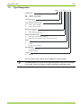
Type Designation
ZMF 1 10 A B e F s2
Network Type
ZFF 3 phase 3 wire network
ZMF 3 phase 4 wire network
Connection Type
1
Direct connection
Accuracy Class active energy
10
Class 1 (IEC); B (MID)
20
Class 2 (IEC); A (MID)
Measured Quantities
A
C
Active energy
Active and reactive energy
Additional Functionality
C
Meter with communication interface
B
Meter with communication interface and disconnector
Rates
e
d
1 rate
2 rates
t
Multirate (up to 6 rates)
Anti-tampering
No tamper detection
F
Tamper detection
Version
s2
Series 2
The "e" for the 1-rate version can be skipped in some versions.
The AMR Module is not part of this type designation, since it is a complete
unit in itself. Users can change it without opening the calibration seal.
D000027979 EN n – E350 series 2 ZxF100Ax/Cx – User Manual
© Landis+Gyr
10/54
Description of Unit
1.6
Measuring Principle
1.6.1
Overview
The main meter inputs are:
Inputs
Phase connection (L1, L2, L3) and neutral for
- energy measurement
- three-phase power supply of the meter
- PLC communication with communication modules (all phases
prepared)
Display button
Disconnector button (only if meter equipped with disconnector)
The main meter outputs (partly also inputs) are:
Outputs
LCD to display measured values and the corresponding OBIS code
Optical test outputs (red, one for active and one for reactive energy)
Optical interface for automatic data readout on site by means of a
suitable HHT (Hand Held Terminal) (also input)
Secured AMR Interface for automatic data readout through an AMR
module, e.g. E35C module, with a PLC, GSM/GPRS, Ethernet or other
medium (also input).
Power supply
The supply voltage for the meter electronics is taken from the three-phase
system. A voltage monitor guarantees a safety data storage in the event of
a mains voltage failure and a correct start-up after the return of the voltage.
Memory
A non-volatile memory (EEPROM) contains the parameter set of the meter
and secures the stored measurements against loss due to power failure.
1.6.2
Signal Generation
The three measuring elements, DFS (Direct Field Sensor), register the
phase currents with the magnetic field of the current loops and the phase
voltages over a resistor divider. The analog/digital converters transform
both signals into digital voltage and current data. This data is then multiplied by a digital multiplier to produce an energy proportional value. The
resulting value is fed into the microprocessor, which adds the value to the
corresponding values of the other phases and the sum is then transferred
into the corresponding energy registers (rate-dependent).
The microprocessor generates pulses for the test diodes from the digital
sum to the meter constant R.
1.6.3
Signal Processing
The meter records active and reactive energy and can distinguish between
energy import and export in up to 6 rates (depending on configuration).
Calibration
© Landis+Gyr
Calibration data is stored during the final testing of the meter.
D000027979 EN n – E350 series 2 ZxF100Ax/Cx – User Manual
Description of Unit
11/54
Start detection
The microprocessor compares the measured power with the minimum
starting power. The signals are only passed on for summation if the minimum starting power is exceeded.
Measured quantities
The following energy values can be measured and stored in the registers:
Active energy A
Reactive energy R
Apparent energy S
The signals +A and +R are formed by summation for imported measured
active and reactive energy. The signals –A and –R are formed by summation for exported measured active and reactive energy. The combined totals
are the sum of the absolute values of +A and –A or +R and –R.
Energy type:
kWh, kvarh or kVAh
Direction:
Import, export, ± reactive
Source:
Individual phase, summed etc.
Instantaneous Values:
Voltage, current, frequency, power factor
Measurement
channels
There are 8 independent measurement channels. One of the measured
quantities can be assigned to each of this register.
Energy registers
The measurement channels 1 to 6 have 6 rated registers and 1 total each,
channel 7 and 8 have only 1 total register. 44 registers are therefore available in total.
All registers work internally with 9 digits. The internal magnitude is Wh
(Watt-Hours). They cannot be reset. At 999999999, a rollover to 0 takes
place. The display and readout formats vary from the internal format.
Rates
The meter is designed for up to 6 rates. The assignment of the rate registers is done by means of parameterisation and is shown on the face plate.
Rate control is performed by the external module.
Rate control
With up to 2 rates, the rate switching is operated by the AMR Module directly
or by control inputs. The rate switching for more than 2 rates can be operated only by the AMR module.
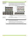
Summation methods
Summation can take place in different ways:
Summation by vectors "Ferraris mode":
As in Ferraris meters the meter summates the values of the individual
+A/–A
phases taking account to the sign. With differing signs (energy directions)
the sum corresponds to the difference between the positive and negative
values as shown in the figure below.
If the vectorial sum of the three vectors AL1, AL2, AL3 is positive, then active
energy is imported (+A).
If the vectorial summation of all three vectors AL1, AL2, AL3 is negative, then
active energy is exported (–A). See following figure.
The same applies to reactive energy. A distinction of the different quadrants
is also possible.
D000027979 EN n – E350 series 2 ZxF100Ax/Cx – User Manual
© Landis+Gyr
12/54
Description of Unit
10 kWh
10 kWh
0 kWh
0 kWh
–10 kWh
–10 kWh
1st hour
2nd hour
3rd hour
1st hour
2nd hour
L1
2 kWh
2 kWh
2 kWh
L1
2 kWh
2 kWh
2 kWh
L2
5 kWh
5 kWh
-5 kWh
L2
5 kWh
5 kWh
-5 kWh
L3
-3 kWh
3 kWh
-3 kWh
4 kWh
10 kWh
0 kWh
4 kWh
14 kWh
14 kWh
-3 kWh
3 kWh
-3 kWh
L3
Sum
4kWh
10 kWh
-6 kWh
Sum
Sum kum
4 kWh
14 kWh
8 kWh
Sum kum
3rd hour
Fig. 1.2 Example vectorial summation active energy (left ±A, right: only +A)
Summation by
quantity (magnitude)
Σ+A/Σ–A
Summation by quantity separates the positive from the negative values of
the individual phases. Measured quantity +A therefore only includes the
positive values (+A1 and +A3 in example 1), measured quantity –A only
the negative values (–A2 in example 1), provided any are present.
In case of a connection error the meter measures correctly the real energy
consumption. It also measures a real export in the correct way.
For active energy import (+A) only positive magnitudes of AL1, AL2, AL3 are
counted. Negative magnitudes of AL1, AL2, AL3 are discarded.
For active energy export (–A) only negative magnitudes of AL1, AL2, AL3 are
counted. Positive magnitudes of AL1, AL2, AL3 are discarded.
The same applies to reactive energy. A distinction of the different quadrants
is also possible.
The following examples show the magnitude summation for active energy
import (left) and for active energy export (right).
20 kWh
20 kWh
10 kWh
10 kWh
0 kWh
0 kWh
–10 kWh
–10 kWh
1st hour
2nd hour
3rd hour
2 kWh
2 kWh
2 kWh
L1
L2
5 kWh
5 kWh
-5 kWh
L3
-3 kWh
3 kWh
-3 kWh
Sum
7 kWh
10 kWh
2 kWh
Sum kum
7 kWh
17 kWh
19 kWh
L1
1st hour
2nd hour
3rd hour
2 kWh
2 kWh
2 kWh
L2
5 kWh
5 kWh
-5 kWh
L3
-3 kWh
3 kWh
-3 kWh
Sum
3 kWh
0 kWh
8 kWh
Sum kum
3 kWh
3 kWh
11 kWh
Fig. 1.3 Example magnitude summation active energy (left: +A, right –A)
Summation by single
quantities
Σ |A Lx|
This method summates the quantity of the individual phases independent
of the energy direction. A connection error – however – has no effect on the
result of measurement.
But if there is a real export in one phase, this method leads to incorrect
measurement results.
© Landis+Gyr
D000027979 EN n – E350 series 2 ZxF100Ax/Cx – User Manual
Description of Unit
13/54
With this method the meter adds exported and imported energy. This
method only makes sense if the utility is sure there is no energy export.
This method is available in vectorial and magnitude summation mode.
Summation by
Absolute value
|+A| + |–A|
The absolute magnitude summation can be used as an anti-tampering
measure. Here negative magnitudes of AL1, AL2, AL3 are added to the positive
magnitudes of AL1, AL2, AL3. See example below.
30 kWh
20 kWh
20 kWh
10 kWh
10 kWh
0 kWh
0 kWh
–10 kWh
–10 kWh
1st hour
2nd hour
3rd hour
L1
2 kWh
2 kWh
2 kWh
L1
L2
5 kWh
5 kWh
-5 kWh
L3
-3 kWh
3 kWh
-3 kWh
Sum
4 kWh
10 kWh
6 kWh
Sum kum
4 kWh
14 kWh
20 kWh
1st hour
2nd hour
3rd hour
2 kWh
2 kWh
2 kWh
L2
5 kWh
5 kWh
-5 kWh
L3
-3 kWh
3 kWh
-3 kWh
Sum
10 kWh
10 kWh
10 kWh
Sum kum
10 kWh
20 kWh
30 kWh
Fig. 1.4 Example absolute value summation active energy (left: combined sum,
vectorial, always positive; right: combined sum, magnitude, always positive
per phase)
With this method the meter subtracts an exported energy from the imported. It cannot detect a connection error.
Subtraction
|+A| – |–A|
Use of vectorial and magnitude mode
ZFF meters must work in vectorial mode – we don’t have energy values for
each phase (3 phases and only 2 measurement systems).
For ZMF most of the customers use vectorial mode too. Only some
customers use magnitude mode, mainly for tamper prevention.
D000027979 EN n – E350 series 2 ZxF100Ax/Cx – User Manual
© Landis+Gyr
14/54
Description of Unit
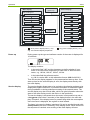
Calculation
method
Example 2
Example 1
A1
A2
A3
Register content
without sign
A1
+A
A1
A2
A3
A2
A3
A3
–A
A1
A2
A1
+A
–A
A2
A2
A3
A3
A Lx
+A – –A
A1
A2
A1
A2
A3
A1
A3
+A + –A
A2
A3
A1
A2
A3
A1
A1
A2
A3
A3
A1
A2
Fig. 1.5 E350 – Phase summation samples
Further measurement
quantities
In addition to the usual quantities, the measured quantities active, reactive
and apparent energy have further possibilities such as:
Subtraction of reactive energy
|+R| – |–R|
Addition of reactive energy
|+R| + |–R|
Quadrants
+Ai, +Ac, –Ai, –Ac
etc.
Further samples
More samples and applications are shown in the functional description.
4-quadrant
measurement
The reactive energy (±Rc, ±Ri) is allocated to the 4 quadrants as follows:
+R
+ kvarh
+ kvarh
+Rc
+Ri
Quadrant II
Quadrant I
Export -A
- kWh
+A Import
Quadrant III
Quadrant IV
-Ri
-Rc
- kvarh
+ kWh
- kvarh
-R
Fig. 1.6 4-quadrant measurement (only in ZxF100Cx meters)
The reactive energies of the individual phases can be allocated to the 4
quadrants in the same way.
© Landis+Gyr
D000027979 EN n – E350 series 2 ZxF100Ax/Cx – User Manual
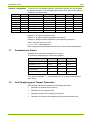
Description of Unit
15/54
Channel configuration
Value
+A
+A
–A
|+A| + |–A|
+R
+R
+R
–R
To each of the 8 available channels a measured quantity can be assigned
by parameterisation. The following table shows some of the most common
measured quantities used:
OBIS
1.8.0
1.8.0
2.8.0
15.8.0
3.8.0
5.8.0
6.8.0
4.8.0
Direction
Import
Import
Export
Combined sum
Import
Import
Import
Export
Quadrant(s)
I + IV
I + IV
II + III
I + II + III + IV
I + II
I
II
III + IV
Phase
Sum
L1 + L2 + L3
Sum
Sum
Sum
Sum
Sum
Sum
Unit
kWh
kWh
kWh
kWh
kvarh
kvarh
kvarh
kvarh
Remarks
1
2
3
Remark 1: by vector (Ferraris mode)
Remark 2: by signal values (magnitude summation)
Remark 3: always positive registration (anti-tampering measure)
Sum = vectorial sum of ALi or RLi
L1 + L2 + L3 = magnitude sum
More configuration possibilities can be found in the functional description.
1.7
Instantaneous Values
Instantaneous values are updated every second.
The following instantaneous values are available:
Measured value
Resolution
Start value
Max. value
Voltages L1, L2, L3
1V
170 V
440 V
Currents I1, I2, I3
0.01 A
0.2 A
120 A
Frequency
0.1 Hz
47 Hz
53 Hz
Power Factor
0.1
-1
1
Power
0.01 kW
I > 0.075 Ib
Imax
If no value is available "---" can be shown (e.g. if in creep or value below
start value).
1.8
Anti-Tampering and Tamper Prevention
E350 meters feature four optional anti-tampering functions:
Detection of terminal cover opening
Detection of DC magnetic field
Sealable access lock to voltage connections
Detection of Disconnector tampering (Disconnector meters only)
D000027979 EN n – E350 series 2 ZxF100Ax/Cx – User Manual
© Landis+Gyr
16/54
1.9
Description of Unit
Disconnector
The ZxF100xB version of the E350 meter is equipped with a disconnector
which is controlled via the communication module. Various functions can be
implemented:
disconnection if credit has been used up
change to minimum power mode if credit has been used up
disconnection if max. power has been exceeded over a specified time
others
The disconnector can either be controlled via the AMR module or manually
with the disconnector button on the meter’s terminal cover (if parameterised
accordingly, see also section 5.1.2 "Disconnector Button").
1.10
Software Tools
Landis+Gyr meters are provided with optimum support by suitable software
tools during all phases of their life cycle:
The Landis+Gyr MAP110 service tool for customers is used for the test
and installation of meters and for servicing work on the spot.
For the list of functions of MAP110 please see MAP-documentation and
functional description of the E350.
© Landis+Gyr
D000027979 EN n – E350 series 2 ZxF100Ax/Cx – User Manual
Safety
2
17/54
Safety
This section describes the safety information used in this manual, outlines
the responsibilities and lists the safety instructions to be observed.
2.1
Safety Information
Attention is drawn to dangers and their level (severity and probability) in
this user manual in the following way:
Definition of Danger
For a possibly dangerous situation, which could result in severe physical
injury or fatality.
Definition of Warning
For a possibly dangerous situation, which could result in minor physical
injury or material damage.
Definition of Note
For general details and other useful information to simplify work.
All safety information also describes the type and source of the danger, its
possible consequences and measures to counteract the danger.
2.2
Responsibilities
The owner of the meters is responsible that all persons engaged on work
with meters:
1.
Are competent and qualified in accordance with national regulations
(see ISSA "Guideline for Assessing the Competence of Electrically
Skilled Persons").
2.
Have read and understood the relevant sections of the user manual.
3.
Strictly observe the safety instructions (according to section 2.3) and
the operating information in the individual sections.
In particular, the owner of the meters bears responsibility
for the protection of persons,
prevention of material damage
and the training of personnel.
Landis+Gyr AG provides training courses for this purpose on specific
equipment; please contact the relevant agent if interested.
D000027979 EN n – E350 series 2 ZxF100Ax/Cx – User Manual
© Landis+Gyr
18/54
2.3
Safety
Safety Instructions
The following safety instructions must be observed at all times:
2.4
The meter connections must not be under voltage during installation or
when opening. Contact with live parts is dangerous to life. The relevant
main fuses should therefore be removed and kept in a safe place until
the work is completed, so that other persons cannot replace them unnoticed.
Local safety regulations must be observed.
Protection earth connection must not be switched with the disconnetor.
Only "useful" tools have to be used. This means a screw driver has to
have the correct size for the screws and the metallic part of a screw
driver has to be insulated.
The meters must be held securely during installation. They can cause
injuries if dropped.
Meters which have fallen, must not be installed, even if no damage is
apparent, but must be returned for testing to the service and repair department responsible (or the manufacturer). Internal damage can result
in functional disorders or short-circuits.
The meters must on no account be cleaned with running water or with
compressed air devices. Water penetrating can cause short-circuits.
Radio Interference
© Landis+Gyr
Possible radio interference in residential environments
This meter is normally a class B product. In combination with some communication modules it can become a Class A product. In a domestic environment, this may then cause radio interference, in which case the user may
be required to take adequate measures.
D000027979 EN n – E350 series 2 ZxF100Ax/Cx – User Manual
Mechanical Description
19/54
3
Mechanical Description
3.1
Housing
The internal construction of the meter will not be described here, as the
meter is sealed after calibration and verification.
1
2
3
5
4
5
6
7
8
9
10
10
11
12
13
13
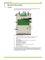
Fig. 3.1 Front view of meter
1
2
3
4
5
6
7
8
9
10
11
12
13
Front cover (face plate with laser marking, for details see Fig. 3.2)
Suspension hanger (not inserted for covered mounting)
LCD
Display button
Screw with sealing point (manufacturer or verification seal)
Optical interface
Test diode active energy (red)
Test diode reactive energy (red)
AMR Module compartment
Screw with sealing point (manufacturer or utility seal)
Terminal cover
Disconnector button
Screw with sealing point (utility seal)
A terminal block with all connecting terminals is located under the terminal
cover. On the terminal cover, two sealing points for utility seals prevent
unauthorised access to the phase connections and therefore help to avoid
unrecorded power consumption.
D000027979 EN n – E350 series 2 ZxF100Ax/Cx – User Manual
© Landis+Gyr
20/54
3.2
Mechanical Description
Face Plate
The face plate (laser marking on front cover) shows customer specific
meter information.
Fig. 3.2 Basic layout of face plate
1
2
3
4
5
6
Meter data
Double protection insulation symbol
Approval symbol, CE conformity symbol
Customer No. / Barcode / Ownership designation
Active rate
Connection diagram
The display key and the display are fully described in section 5.
3.3
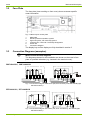
Connection Diagrams (examples)
Where to find relevant diagrams
The diagrams relevant for the installation are shown on the meter’s face
plate or specified otherwise (e.g. inserted in the terminal cover).
ZMF100AC/CC, ZMF100AB/CB
N
N
Fig. 3.3 Connection diagram ZMF100xC (left, M-Connection) and ZMF100xB (right,
with disconnector)
ZFF100AC/CC, ZFF100AB/CB
Fig. 3.4 Connection diagram ZFF100xC (left, Aron-Connection), ZFF100xB (right,
with disconnector)
© Landis+Gyr
D000027979 EN n – E350 series 2 ZxF100Ax/Cx – User Manual
Mechanical Description
3.4
21/54
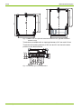
Dimensions
The meter is either available with a standard terminal cover (see Fig. 3.5)
or with an extended terminal cover (see Fig. 3.6)
84
203
173
140
72
176
Fig. 3.5 Meter dimensions (version with short terminal cover)
84
260
173
140
72
176
Fig. 3.6 Meter dimensions (version with 60 mm terminal cover)
The meter with extended terminal cover offers increased safety since the
phase connecting wires are protected under the terminal cover.
The suspension triangles are identical with both terminal covers. They
comply with DIN standards.
D000027979 EN n – E350 series 2 ZxF100Ax/Cx – User Manual
© Landis+Gyr
203
180
162
203
180
Mechanical Description
162
22/54
150
150
Fig. 3.7 Meter rear view (left with standard terminal cover, right with extended
terminal cover)
Terminals are available with an opening diameter of 8.5 mm and 9.5 mm.
40
15.4
13.25
Terminals with opening diameter of 8.5 mm and 9.5 mm have the same
position on the terminal block.
13
16
16
19
16
13
16
13
Fig. 3.8 Terminal layout and dimensions
© Landis+Gyr
D000027979 EN n – E350 series 2 ZxF100Ax/Cx – User Manual
Installation/De-installation
23/54
4
Installation/De-installation
4.1
Mounting the Meter
The meter should be mounted as follows on the meter board or similar device provided for this purpose (see also section 3.4 "Dimensions"):
2.
Define the desired form of fixing (open or covered meter mounting).
3.
Ensure with a phase tester or universal measuring instrument that the
connecting wires are not live.
75 mm
162 mm for covered mounting
Find the correct position for the meter. Ensure there are no wires
underneath the holes to be drilled.
180 mm for open mounting
1.
150 mm
Fig. 4.1 Drilling plan
4.
Mark the three fixing points (suspension triangle as shown in the drilling plan Fig. 4.1) on the mounting surface provided.
5.
Drill the three holes.
6.
Unscrew the meter terminal cover.
7.
For open meter mounting insert the meter suspension eyelet – this is
supplied in the terminal cover – into the corresponding opening at the
rear side of the meter until the suspension eyelet engages (see Fig. 4.2).
Fig. 4.2 Meter suspension eyelet
8.
Fit the meter with 3 fixing screws on the mounting surface provided.
D000027979 EN n – E350 series 2 ZxF100Ax/Cx – User Manual
© Landis+Gyr
24/54
4.2
Installation/De-installation
Connecting the Meter
Remove main fuses before connecting
The connecting wires at the place of installation must not be live when fitting the meter. Touching live parts is dangerous to life. Remove the corresponding main fuses and keep them in a safe place until work is completed,
so that they cannot be replaced by anyone unnoticed.
Provide overcurrent protection
For ZxF100xB meters: As the disconnector is not equipped with a thermal
and/or short circuit protection device, it needs to be protected with an external fuse or overload switch.
For ZxF100xC meters: As the meter has no internal overcurrent protection
and no method of disconnection from the mains, this must be provided by
the end installation.
Connecting the phase connection lines
1.
2.
Shorten the phase connecting wires to the required length and then
strip them.
Insert the phase connecting wires into the corresponding terminals (the
terminals are numbered as shown in the connection diagram) and tighten
the terminal screws firmly (max. torque 3 Nm).
It is recommended to identify the beginning and end of the relevant conductors with a suitable test unit (e.g. buzzer) to ensure that the right consumer
is connected to the meter output.
L1
L2
L3
N
Phase connections
Fig. 4.3 Meter connections
With small conductor cross-sections (e.g. 4 mm2) the connecting line must
be placed in the indentation (stamping) of the current loops, so that it cannot shift sideways when tightening the terminal screws. Ensure that the
connecting line remains in the indentation when tightening.
Indentation (stamping) for smaller connection lines
Current loop conductors
Fig. 4.4 Cross-section through current loop conductor
© Landis+Gyr
D000027979 EN n – E350 series 2 ZxF100Ax/Cx – User Manual
Installation/De-installation
25/54
Insufficiently tightened screws
Insufficiently tightened screws of the connections can lead to increased
power losses at the terminals and therefore to undesirable heating. A
contact resistance of 1 m causes a power loss of 6.4 W at 80 A!
Insulate to correct length
Touching live parts is dangerous to life. Shorten the stripped part of the
connecting wire if bare wire is visible above the terminal edge.
Do not withdraw connecting wires with closed terminals
Never withdraw connecting wires with the terminal closed, since this could
damage the terminal.
4.3
Checking the Connections
Before putting the meter into operation check (and correct, if necessary) the
following points to ensure a correct connection:
1.
Has the correct meter (identification number) been installed at the
measuring point of the relevant consumer?
2.
Is the calibration connection closed (sealable sliding piece inserted
and sealed)?
3.
Are all screws for the phase and neutral connections tightened well?
4.
Are all inputs and outputs connected correctly? The house connection
or consumer fuse wires must be present at the input (terminals 1, 4, 7),
those of the meter to the consumer at the output (terminals 3, 6, 9).
5.
Is the neutral conductor connected to terminals 10 and 12?
Interchanging of a phase with the neutral could destroy the meter.
Mount the terminal cover after a successful check of the connections,
tighten its screws and seal it.
4.4
Commissioning and Functional Check
Do not touch live parts
The main fuses must be inserted to put the meter into operation and for the
functional check. Without terminal cover there is a danger of contact with
the terminals. Touching live parts is a danger to life.
The installed meter should be put into service and checked as follows:
1.
Insert the corresponding main fuses. The meter is on.
2.
Check whether the display appears correctly (no error message) and
with no load connected that the anti-creep indicators are constantly on.
3.
Connect a load and check whether the anti-creep indicator for active
energy disappears.
4.
Check whether the disconnector (if present) works according to the
functionality specified for your application.
D000027979 EN n – E350 series 2 ZxF100Ax/Cx – User Manual
© Landis+Gyr
26/54
4.5
Installation/De-installation
Disconnecting the Meter
Remove main fuses before disconnecting
The connecting wires at the place of installation must not be live when
removing the meter. Touching live parts is dangerous to life. The corresponding main fuses should be removed and kept in a safe place until work
is completed, so that they cannot be replaced by anyone unnoticed.
For ZxF100xB: Do not use the disconnector as a main switch for
disconnecting purposes! The meter remains connected to the mains!
Remove the meter from the network as follows:
© Landis+Gyr
1.
Switch off the voltage. The display goes off.
2.
Remove the seal at the terminal cover.
3.
Release and remove the terminal cover.
4.
Ensure with a phase checker that the connecting wires have no
voltage. If there is voltage, remove the main fuses.
5.
Remove the connecting wires of the AMR Module, if available.
6.
Loosen the terminal screws of the phase and neutral connecting wires
with a suitable screwdriver and withdraw the wires from the terminals.
7.
Fit a substitute meter as described in section 4.2 "Connecting the
Meter" and the following sections, if necessary.
D000027979 EN n – E350 series 2 ZxF100Ax/Cx – User Manual
Operation
27/54
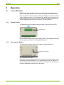
5
Operation
5.1
Control Elements
E350 meters have a display button on the front cover and a disconnector
button on the terminal cover, if the meter is equipped with a disconnector.
Data acquisition is either made by reading the display or automatic readout
via the optical interface. For this purpose, the optical head is placed on the
marked position on the front cover of the meter and readout is performed
with a handheld terminal (refer to section 5.5 "Data Readout").
5.1.1
Display Button
The display button is located on the front cover on the right of the LCD.
Display button
Fig. 5.1 Display button
By pressing the display button, the display mode or the displayed value can
be changed (see section 5.2.4 "Display Definitions").
5.1.2
Disconnector Button
The disconnector button (option) is located on the terminal cover.
Disconnector button
Fig. 5.2 Disconnector button
If the disconnector button is pressed, the disconnector opens and/or closes
depending on parameterisation, i.e. a closed disconnector can always be
opened with the disconnector button whereas closing an open disconnector
needs an additional permission from the meter.
D000027979 EN n – E350 series 2 ZxF100Ax/Cx – User Manual
© Landis+Gyr
28/54
Operation
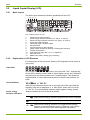
5.2
Liquid Crystal Display (LCD)
5.2.1
Basic Layout
The basic layout shows all indication possibilities of the LCD.
1
2 3 3
2 4
5
m3
+Q
-P
MJ
GJ
+P
-Q
L1 L2 L3 VA k
12
11
10
9
8
6
arh
7
Fig. 5.3 Basic layout of LCD
1
2
3
4
5
6
7
8
9
10
11
12
5.2.2
Reactive anti-creep indication
Active energy direction indication (+P: import, -P: export)
Reactive energy direction indication (+Q: import, -Q: export)
Active anti-creep indication
Value field (eight 7 segment digits)
Unit indications
6 arrow symbols for rate indication
Phase voltage indications (flashing if rotating field reversed)
Tamper alert indicator
Index field (five digits with 7, 8 or 11 segments)
Disconnect icon
Media icons (water, heating, gas, electricity)
Explanation of LCD Elements
For the purpose of this document, flashing LCD segments will be shown in
grey colour.
Value field
Up to 8-digit values can be displayed in the value field. The 7 segment digits are able to display numeric data or limited alpha numeric text. Additional
decimal points and colons enhance the 7 segment digits. This allows the
representation of values with decimal places as well as date and time formats.
Unit indications
VA k
arh
m3 MJ GJ
With the unit indications below and on the right side of the value field the
following units can be displayed: V, A, kWh, kVah, kVarh, kW, kVa, kVar,
m3, MJ, GJ. The unit displayed indicates which register is being viewed.
Active energy
direction indication
Always indicates the sum of the three phases:
+P
-P
negative active energy direction (exported to power company)
-P
+P
© Landis+Gyr
positive active energy direction (imported from power company)
positive active energy direction, but negative active energy
direction of individual phases (arrow -P flashes); only in threephase four-wire circuit (only with magnitude summation).
D000027979 EN n – E350 series 2 ZxF100Ax/Cx – User Manual
Operation
29/54
-P
+P
Reactive energy
direction indication
Always indicates the sum of the three phases:
+Q
positive reactive energy direction
negative reactive energy direction
-Q
+Q
positive reactive energy direction, but negative reactive energy
direction of individual phases (arrow -Q flashes); only in threephase four-wire circuit (only with magnitude summation)
+Q
negative reactive energy direction, but positive reactive energy
direction of individual phases (arrow +Q flashes); only in threephase four-wire circuit (only with magnitude summation)
-Q
-Q
Quadrant
negative active energy direction, but positive active energy
direction of individual phases (arrow +P flashes); only in threephase four-wire circuit (only with magnitude summation)
Indicates in which quadrant the present measurement is made:
+Q
1st quadrant
-Q
+P
-P
+Q
3rd quadrant
-P
2nd quadrant
-Q
Reactive anti-creep
indication
Active anti-creep
indication
+P
4th quadrant
The reactive anti-creep indication (a diamond) shows that the kvarh registers have entered anti-creep mode. No energy is flowing through the meter
(no reactive energy direction indicator displayed).
The active anti-creep indication (a circle) shows that the kWh registers
have entered anti-creep mode. No energy is flowing through the meter
(no active energy direction indicator displayed).
Media icons
The media icons represent the medium measured (from left to right water,
gas, heating and electricity). The media icon displayed corresponds to
group A of the OBIS identification code (see also section 5.2.3).
The electricity media icon is either on if data from the internal meter is displayed or is flashing if data from an external meter is displayed (automatically controlled). The water, gas and heating media icons are also flashing
if data from an external source is displayed.
Disconnect icon
This icon indicates that the respective media (represented by the
displayed media icon) is disconnected by the disconnector.
Icon ON:
Icon OFF:
Icon flashing:
Disconnector open (circuit interrupted)
Disconnector closed (circuit closed, current can flow)
Disconnector open, can be closed locally (Push Button)
D000027979 EN n – E350 series 2 ZxF100Ax/Cx – User Manual
© Landis+Gyr
30/54
Operation
This operation is the preset. The operation will be controlled by the installed
module. Please refer to the manual of the module for valid operation mode.
Alternatively to this indication a display of the disconnector status can be in
the installed module and the display on the LCD can be disabled.
Tamper alert
indicator
Phase voltage
indications
This icon is switched on when the meter has detected the tamper event
parameterised (either terminal cover, disconnector or strong magnetic
field).
L1 L2 L3
The phase voltage indications are switched on if the respective phase voltages are present. It can be selected by parameterisation whether all the
phase voltage indications are flashing if the rotating field goes in the wrong
direction and/or whether they are flashing if the energy flow is reverse in
the corresponding phase.
Arrow symbols
The 6 arrow symbols indicate the active rate as marked on the face plate.
It can be parameterised whether the arrow symbol for the active rate is on
or flashing.
Index field
Up to 5-digit indices are displayed in this field which define the value in the
value field with groups C, D and E of the OBIS identification code (see following section).
Examples:
1.8.0 indicates that the status (group D = 8) of total (group E = 0) active
energy import of all phases (group C = 1) is displayed in the value field.
0.9.1 indicates that the local time is displayed in the value field.
5.2.3
Displaying OBIS Codes
For OBIS (Object Identification System) the structure A-B:C.D.E.F applies.
The individual groups have the following significance:
© Landis+Gyr
A
Defines the medium, e.g. electricity, gas, heat or water-related data.
Group A is represented with the media icons.
B
Group B is not shown on E350 meters (only channel 1 available).
C
Defines the measured quantity, the abstract or physical data items related to the information source concerned, e.g. active power, reactive
power, apparent power, power factor, current or voltage.
D
Defines types, or the result of the processing of physical quantities according to various algorithms. The algorithms can deliver energy and
demand quantities as well as other physical quantities.
E
Defines the rates in use. For abstract data or for measurement results
without rates, this value group can be used for further classification.
F
Group F is not shown on E350 meters.
D000027979 EN n – E350 series 2 ZxF100Ax/Cx – User Manual
Operation
31/54
Representation
example
OBIS identification code 1-1:31.7.1.0 (line current in phase L1) is represented as follows on the display:
+P
L1 L2 L3
A
Group A of the OBIS identification code is represented by the media icon
for electricity, groups B and F are not displayed and groups C to E are represented as index value 31.7.1.
The line current in phase L1 is indicated with 25.24 A.
The active energy direction arrow +P, the phase voltage indications L1, L2
and L3 and the arrow symbol of the current rate are also displayed.
5.2.4
Display Definitions
The meter can show various displays. Here are some examples.
Note
The number of digits and decimal places displayed can be parameterised
(also whether leading zeros are to be displayed).
The following examples show different settings.
Total power factor
Total active energy import
+Q
+Q
+P
+P
L1 L2 L3
k
L1 L2 L3
h
Mains frequency
Total reactive energy import
+Q
+Q
+P
+P
L1 L2 L3
k
L1 L2 L3
arh
Status code
Active energy import rate 1
+Q
+Q
+P
+P
L1 L2 L3
k
L1 L2 L3
h
Phase fail counter L1
Active energy export rate 2
+Q
+Q
+P
+P
L1 L2 L3
k
L1 L2 L3
h
Manufacturer identification number
Line voltage L1
+Q
+Q
+P
+P
L1 L2 L3 V
D000027979 EN n – E350 series 2 ZxF100Ax/Cx – User Manual
L1 L2 L3
© Landis+Gyr
32/54
Operation
Water consumption
Line current L3
m3
+Q
+P
L1 L2 L3
L1 L2 L3
A
Heat consumption
Total active energy
+Q
MJ
+P
L1 L2 L3
k
L1 L2 L3
h
Gas consumption
Reactive energy L1
m3
+Q
+P
L1 L2 L3
5.2.5
k
arh
L1 L2 L3
Display Sequence
The previous section showed in detail the possible displays. The display
sequences shown on any specific customer’s product are set through parameterisation at the factory.
There are two display sequences:
Main display (with an auto scrolling list and a recall list)
Service display (with the service list)
The main display can include up to 31 displays, the service display up to 63
displays (defined by parameterisation).
The parameters which have an influence on the display sequence must be
defined in the configuration process.
These items are:
© Landis+Gyr
Leading zeros can be enabled/disabled for registers
Energy register displays can be defined with an integer part of 6 digits
(in exceptional cases 5) and with 0, 1, 2 or 3 decimal places. Max. 6
significant digits (left of the decimal point) are allowed. Max. 8 digits
including decimal places are available.
Only 6 integer digits are allowed for meters according MID.
Active rate indication can be enabled or disabled
Flashing decimal point to indicate that the meter is in the certification
display sequence
D000027979 EN n – E350 series 2 ZxF100Ax/Cx – User Manual
Operation
33/54
Main display
Meter start
(power up)
Auto scrolling list
Service display
Service list
Value 1
Value 1
Value 2
Value 2
Value n
Value 3
Value 4
Recall list
Consumption since reset
Reset of
register
Value 5
Value 2
Value 6
Value 3
Value y
Value x
= short press of display button (< 5 s)
= long press of display button (> 5 s)
Fig. 5.4 Overview display sequences
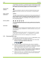
Power up
During power up the type and software version of the meter is displayed for
10 seconds.
The display contains:
In the main field "100" and the characters to define whether it is an
active or a combi meter respectively a meter with or without disconnector, e.g. 100 Ab, 100 AC, 100 bC, 100 bb.
In the index field the software version,
e.g. 21 for version M21 or with alternative format: 2300 for M23.0.0.
Then the service display appears for the parameterised start-up time. If the
start-up time for the service display is zero, the display starts directly with
the main display.
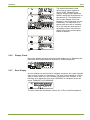
Service display
The service display allows tests to be carried out by allowing registers to be
displayed at higher resolutions. It provides information to assist the installer
during installation or during subsequent testing of the network status. The
service display may also include data, which can give information about the
state of the meter during work in the field or in the test facility.
The service display is accessed when the meter is first powered up and on
a long press (more than 5 seconds) of the display button in the main display. Exception: If the display button is pressed long while the consumption
since last reset is displayed, the register is reset instead.
The items in the service display (maximum 63) can be scrolled through with
short presses (less than 5 seconds) of the display button. When the end of
the sequence is reached, auto scrolling of the main display will start.
D000027979 EN n – E350 series 2 ZxF100Ax/Cx – User Manual
© Landis+Gyr
34/54
Main display
Operation
The number of displays (max. 31), their sequence, whether they are contained in the auto scrolling list or only in the recall list (all displays of the
auto scrolling list appear also in the first part of the recall list) and the display duration for the items (between 1 and 15 seconds) can be parameterised. Up to 12 displays, under the control of the AMR module, can be included in the main display.
The auto scrolling list of the main display is displayed
if the end of the service display or the recall list of the main display is
reached,
if the display button isn’t pressed for a period, configurable at manufacturing, of between 5 and 60 minutes (default 30 minutes), or
after a long press of the display button (more than 5 seconds) in the
service display.
It shows the end-user the main consumption data, e.g. the status of rated
registers and total registers, current instantaneous demand etc. After the
last display in the auto scrolling list it starts again. If the number of displays
in the auto scrolling list is set to 1, auto scrolling is switched off and the first
display of the recall list is displayed continuously.
The recall list of the main display is accessed by a short press (less than
5 seconds) of the display button while the auto scrolling list is running.
A short press moves the display to the next item in the recall list. Repeated short presses will scroll through to the end of the recall list, then
"End" is displayed after which auto scrolling is resumed.
A long press (more than 5 seconds) in the main display will access the
service display. Exception: If the display button is pressed long while the
consumption since last reset is displayed, the register is reset instead.
Example
The following table shows a simple meter main display. The value of the
total active energy import register is assumed to be 000123456 Wh and
that of the total reactive energy import register 000009876 varh. The registers are set to show 6 digits with 1 decimal place. The leading zeros are not
suppressed.
Displayed value
Total active energy import
Total reactive energy import
Display check (all segments on)
Empty display (all segments off)
© Landis+Gyr
D000027979 EN n – E350 series 2 ZxF100Ax/Cx – User Manual
Operation
35/54
+Q
+P
L1 L2 L3
k
h
L1 L2 L3
k
arh
+Q
+P
m3
+Q
-P
-Q
MJ
GJ
+P
L1 L2 L3 VA k
arh
The meter first shows the total
active energy import register as
00123.4 kWh, followed by the
reactive energy import register as
00009.6 kvarh and all segments on
and then all off. The display duration for each display can be set
between 1 and 10 seconds, but not
individually. This sequence is repeated until the meter is switched
off or the recall list (short press of
the display button) or the service
display (long press of the display
button) is entered.
+Q
+P
L1 L2 L3
k
h
L1 L2 L3
k
arh
+Q
+P
etc.
5.2.6
Display Check
During the display check all segments of the display are on. Especially the
index and value fields should be checked for missing segments.
m3
+Q
-P
-Q
MJ
GJ
+P
L1 L2 L3 VA k
5.2.7
arh
Error Display
An error display can be included in a display sequence, but it also automatically turns up in case of a malfunction. The error code is based on a 32 bit
value in which each bit, if set, indicates a particular error condition. In the
following error display the error code "00002002" is composed of the two
errors "00000002" and "00002000".
+Q
+P
L1 L2 L3
The error codes are described in section 6.2.2 "Error Code Descriptions".
D000027979 EN n – E350 series 2 ZxF100Ax/Cx – User Manual
© Landis+Gyr
36/54
5.2.8
Operation
Text Messages on Display
It is possible for the module to show information on the meter display. Possible items include Ids of connected devices, time. For this, the value and
the index fields can be used. This information is available in the module
documentation.
The following characters can be used in text messages:
Character
5.2.9
LCD
Character
LCD
Character
<SPACE>
A
N
– (minus)
B
O
_ (underscore)
C
P
0
D
Q
1
E
R
2
F
S
3
G
T
4
H
U
5
I
V
6
J
W
7
K
X
8
L
Y
9
M
Z
LCD
Display variations
Some characters might be displayed differently, depending on module and
meter version.
Characters which can’t be represented with the 7-segment-display will be
replaced by an underscore (there are also meter versions with a slightly
different character set. E.g. the characters that cannot be shown are
represented with a lower "o").
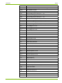
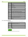
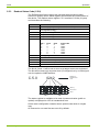
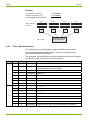
Meter Display List – Available Items with OBIS Codes
© Landis+Gyr
OBIS code
Item
F.F
Error code (always first in the list)
C.1.0
Meter identification (8 character string)
0.0
Customer identification (16 character string) (Readout)
0.0.1
Customer identification (characters 1-8) (Display)
0.0.2
Customer identification (characters 9-16) (Display)
D000027979 EN n – E350 series 2 ZxF100Ax/Cx – User Manual
Operation
37/54
OBIS code
Item
C.1.1
Manufacture identification (8 character string)
C.90.1
IEC-address of meter
1.8.0
Total active energy import
1.8.X
Active energy import rate X (X = 1…6)
2.8.0
Total active energy export
2.8.X
Active energy export rate X (X = 1…6)
3.8.0
Total reactive energy import
3.8.X
Reactive energy import rate X (X = 1…6)
4.8.0
Total reactive energy export
4.8.X
Reactive energy export rate X (X = 1…6)
32.7
Line voltage L1 or L12
52.7
Line voltage L2
72.7
Line voltage L3 or L32
31.7
Line current L1
51.7
Line current L2
71.7
Line current L3
36.7
Active power L1 kW
56.7
Active power L2 kW
76.7
Active power L3 kW
16.7
Total active power kW
33.7
Power factor L1
53.7
Power factor L2
73.7
Power factor L3
13.7
Total power factor
151.7
Reactive power L1 kVar
171.7
Reactive power L2 kVar
191.7
Reactive power L3 kVar
131.7
Total reactive power kVar
14.7
Mains frequency
82.8.2
DC field detection counter
82.8.1
Terminal cover removal counter
82.8.3
Disconnector tamper counter
C.5.0
Status code (see section 5.5.3)
C.7.0
Power off counter
C.7.1
Phase fail counter L1
C.7.2
Phase fail counter L2
C.7.3
Phase fail counter L3
0.2.0
Software version
0.2.1
Parameter identification
D000027979 EN n – E350 series 2 ZxF100Ax/Cx – User Manual
© Landis+Gyr
38/54
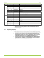
Operation
OBIS code
Item
C.2.0
Number of parameterisations
0.2.1
Scheme ID
All off
Blank display
All on
All segments on
5.8.0
Reactive Energy Q1
6.8.0
Reactive Energy Q2
7.8.0
Reactive Energy Q3
8.8.0
Reactive Energy Q4
9.8.0
Apparent Energy {+kVAh} (Q1+Q4)
10.8.0
Apparent Energy {-kVAh} (Q2+Q3)
15.8.0
Active Energy - Absolute Value [|+A|+|-A|] {+kWh}
16.8.0
Active Energy - Absolute Value [|+A|-|-A|] {+/-kWh}
128.8.0
Active Energy - Sum Phase Absolute Value [‘SUM’ |A Li|] {+kWh}
130.8.0
Reactive Energy - Absolute Value [|+R|+|-R|] {+kvarh}
131.8.0
Reactive Energy - Absolute Value [|+R|-|-R|] {+/-kvarh}
132.8.0
Reactive Energy - Import [+R(Q1+Q4)] {kvarh(+)}
133.8.0
Reactive Energy - Export [-R(Q2+Q3)] {kvarh(-)}
4 Energy efficiency items (see section 5.2.11)
Module data 1 - 12 (value and OBIS code will be sent by module)
End of list
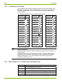
5.2.10 Display Status Messages
Depending from configuration the following messages can appear on the
end of a display list:
Message
Meaning
FF 00000000
Error detected (if error value FF > 0)
rEd
Reverse rotating field detected
td
Terminal cover removal detected
mFd
Strong magnet field tamper detected
btd
Disconnector (breaker) tamper detected
VoltAGE Low
Voltage is lower than the configured threshold (standard value:
170 V)
Fig. 5.5 Sample: Message for magnet tamper detected
© Landis+Gyr
D000027979 EN n – E350 series 2 ZxF100Ax/Cx – User Manual
Operation
39/54
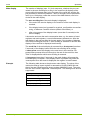
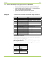
5.2.11 Energy Efficiency Items in the Meter Display
If configured appropriately the display can list 4 new (Software ≥ M23)
items intended to allow the consumer to easily monitor energy flow:
Item
Display
Content
Remarks
Import Energy Meter
St1
Import Energy 1.8.0
Resettable
Export Energy Meter
St2
Export Energy 2.8.0
Resettable
24 Hour Energy
Consumption
24 h
Import Energy 1.8.0
over last 24 h
Refresh
every 5 min
1 Week Energy
Consumption
1w
Import Energy 1.8.0
over last week
Refresh
every 1 hour
The resolution of these 4 displays is 1 W.
Import and Export Energy meter display:
These registers (St1 and St2) are counting energy permanently. The Import
and the Export energy Meter values can be reset by applying a long button
press whilst the register value is being displayed on the meter (working like
a trip recorder in a car).
During power outage registers St1 and St2 are reset. These both registers
start after recover of power with the values of the energy registers of import
or export energy (St1: import, value register 1.8.0; St2: export, value register 2.8.0).
24 hour and 1 week consumption registers:
These registers show the energy consumed during the last period of 1
week (24 h register: period of 1 day).The meter counts the time duration
continuously but doesn’t synchronise with a calendar clock.
Time during power outages is not included in the elapsed time measurements of the registers "24 Hour Energy Consumption" and "1 Week Energy
Consumption".
E.g. for the 24 h register assume registration for 5 hours followed by 1 hour
power outage. Then completion of the 24 h registration will complete 19
hours following the end of the outage (5 h + 19 h = 24 h).
After resumption of power following an outage, the registers "24 Hour
Energy Consumption" and "1 Week Energy Consumption" will display "0"
until the first refresh occurs (i.e. after 5 min and 1 hour respectively).
D000027979 EN n – E350 series 2 ZxF100Ax/Cx – User Manual
© Landis+Gyr
40/54
5.3
Operation
Optical Test Outputs
The test diodes – one for active and one for reactive energy – are used for
meter testing. They transmit visible red pulses equivalent to the currently
measured value. The number of pulses per time unit depends on the meter
constant (as stated on the face plate). When registering energy the test
diodes will flash at a rate of 1 pulse per Wh or VArh of energy recorded.
The pulse width is 10 ms.
Optical interface
Test diode active energy
Test diode reactive energy
Fig. 5.6 Optical test outputs and optical interface
5.4
Optical Interface
All meters have an optical communications port (see Fig. 5.6). If the AMR
module supports this function, both meter and module can be accessed via
optical port. In this case, the AMR module has to be addressed.
The optical interface allows reading the meter’s registers and identity in the
field using a suitable device (Hand Held Terminal or PDA). The readout list is
in full accordance with the provisions of IEC62056-21. The optical port is
normally closed, a wake up string is sent to the meter, which activates the
readout list.
With this communication channel, software can be downloaded to the
module. Additionally, an external user can send commands to the module
and upload data from the module via the opto port. All communication is
half-duplex, i.e. data can either be transmitted or received at any point in
time.
If the module communicates with the opto port, the meter will not accept
sign-ons from either the opto port or the AMR port. If the module wants to
read the meter, it must terminate the opto port module communication.
The module communicates normally via dlms.
Access to module
over optical port
Access to module over optical port of meter is possible with
/?xxxxxxxx7214!
where xxxxxxxx is the meter number.
Opening 7214 7 bit, even parity, 1 stop bit, 4800 bps
This can be used to read out the module over the optical meter interface or
to set the TOU-table of the module.
© Landis+Gyr
D000027979 EN n – E350 series 2 ZxF100Ax/Cx – User Manual
Operation
5.5
41/54
Data Readout
The power supplier can read the meter data, particularly the energy consumption, locally in two ways:
Reading the meter’s LCD. Only the data shown in the display list can
be recorded.
Automatic data readout via the optical interface with the aid of an AMR
Module (e.g. hand held terminal T3000). Further data are then accessible depending on the parameterisation (total registers etc.). Log corresponds to the provisions of IEC62056-21, a communication standard
for meters.
5.5.1
IEC 62056-21 Mode C
The meter supports IEC 62056-21 mode C-a. This enables the reading of
data from the meter in the data readout mode. After an initial sign-on sequence, the meter transmits its data to the HHT. This consists of a number
of items which are set in the configuration. Each item is sent in ASCII with
OBIS (IEC 62056-61) identifiers. Each identifier is on a separate line (separated by carriage return and line feed characters CRLF) and follows the format Identifier (value*units).
The maximum transmission rate is 9600 bps. The response message identifies the software version and the IEC 62056-21 transmission rate mode used.
The meter provides also a manufacturer specific mode C-C, which delivers
only a part of the read out list (start and end item are configurable during production). This can be used for fast read out for frequently required values.
5.5.2
Readout Configuration
The readout items, their order in the list, along with the number of decimal
places for the registers, are specified in the configuration. The register
sizes can have up to 6 integer digits and up to 3 decimal places. This is
independent on the display configuration.
The readout list (similar to the display list) consists of a number of specified
items. The customer specifies the readout sequence. This sequence is set
at the factory. All items are identified with OBIS codes when read out.
Readout and
display items
The items that can be placed in the readout list (in any order except for
"Error code" which is always first in the list) are listed in section 5.2.9
"Meter Display List – Available Items with OBIS Codes" on page 36. Most
of these items can be included in the readout list.
Readout error
code (F.F)
The error code consists of 8 bits and describes the following:
Bit number
0
1
2
3
4
5
6
7
Allocation
Not used
MMI initialisation or communications failure
Error accessing EEPROM
Calibration data is corrupted
Not used
Error restoring energy registers
Data saved to EEPROM on power fail is corrupted
Not used
Valid for readout with E35C-modules! For other modules other codes could
be delivered e.g. equal to error display values.
D000027979 EN n – E350 series 2 ZxF100Ax/Cx – User Manual
© Landis+Gyr
42/54
5.5.3
Operation
Readout Status Code (C.5.0)
The E350 devices feature along with universal device status symbol
showed on display also a status register which shows the current status of
the device. The readout status register C.5.0 consists of 16 bits (2 bytes)
and describes the following:
Bit number
0
1
2
3
4
5 to 7
8
9
10
11
12 to 15
Allocation
Reverse (export) detect (cleared after readout)
Creep flag (set on product initialization and cleared when meter
first registers energy)
L1 phase fail flag
L2 phase fail flag
L3 phase fail flag
Active rate (coded):
bit 7
bit 6
bit 5
active rate
0
0
0
rate 1
0
0
1
rate 2
0
1
0
rate 3
0
1
1
rate 4
1
0
0
rate 5
1
0
1
rate 6
Strong magnetic DC field detected
Terminal cover removed
Disconnector state (0 = open, 1 = closed)
Disconnector tamper detected
reserved
The bits 8, 9 and 11 will be set as soon as a tamper event was registered.
The bits will be reset only at power down (if configured) or by a reset signal
over the optical or AMR-interface.
C.5.0
0242
Register in
hexadecimal
code
8 4 2 1
8 4 2 1
8 4 2 1
8 4 2 1
Valency
7 6 5 4
3 2 1 0
7 6 5 4
3 2 1 0
Bit number
0 0 0 0
0 0 1 0
0 1 0 0
0 0 1 0
Value
Byte 2
Byte 1
The status register is available to be read via communication (public or
optical) or displayed on LCD in hexadecimal form.
Some meter configuration contains also a special code which is 4 bytes
long.
All reserved or not used bits are set to 0 by default.
© Landis+Gyr
D000027979 EN n – E350 series 2 ZxF100Ax/Cx – User Manual
Operation
5.5.4
43/54
Data Readout Procedure via Optical Interface or AMR Module
Readout list
(example)
1.
Start the AMR Module (according to the associated user manuals).
2.
Connect the cable of the reader head to the Hand Held Terminal.
3.
Place the reader head in the marked position on the face plate of the
meter. The reader head is held magnetically.
4.
Start the data readout with the Hand Held Terminal.
5.
Remove the reader head from the meter again after readout.
The data read out are recorded in the form shown below. The scope and
sequence of values in the readout list is determined by parameterisation.
Info flow Readout list
→
Significance
/?! CRLF
Opening string (initial sign on)
/LGZ0ZMF100AC.MXXCRLF
Unit recognition for the specific manufacturer
(no identification of data; MXX: SW version)
<ACK>0Z0 CRLF
Acknowledgement; Z: Transmission rate
←
<STX> F.F(00)CRLF
Start of text, Error message (readout flag)*
←
C.1.1(0000000074892473) CRLF
Meter identification number 1
←
1.8.0(000065.3*kWh) CRLF
Total active energy import
←
2.8.0(000003.5*kWh)CRLF
Total active energy export
←
1.8.1(000021.5*kWh)CRLF
Active energy import rate 1
←
1.8.2(00043.8*kWh)CRLF
Active energy import rate 2
←
2.8.1(000001.5*kWh)CRLF
Active energy export rate 1
←
2.8.2(00000.0*kWh)CRLF
Active energy export rate 2
←
C.5.0(03)CRLF
Status code (L2 phase fail flag)
←
!CRLF<ETX><BCC>
End of text, Checksum
←
→
Fig. 5.7 Example of readout list
* Valid for readout with E35C-modules! For other modules other codes could be
delivered e.g. equal to error display values.
<ACK>, <CR>, <LF>, <STX>, <ETX>, <BCC> ASCII character not visualised in the data readout list.
The code Z in the data readout acknowledge string identifies the required
transmission rate for the data to follow:
Code Z
Transmission rate
0
300 bps
1
600 bps
2
1200 bps
3
2400 bps
4
4800 bps
5
9600 bps
D000027979 EN n – E350 series 2 ZxF100Ax/Cx – User Manual
© Landis+Gyr
44/54
5.5.5
Operation
Addressability of Meter
The meter monitors every communication request received over the optical
port or the AMR-interface. The AMR-interface can be controlled by various
inputs from the module (e.g. cs-interface-input).
With SW-versions M23 or higher the meter will react to the communication
request only under either of the following conditions:
-
If the request contains no address,
-
If the address matches with the address of the meter.
The address of the meter is preset to the serial number of the meter.
For SW-versions prior to M23 the meters reacts only if the request contains
no address.
© Landis+Gyr
If the meter is connected to a communication bus with several meters, the
communication request must be started with address. Otherwise a
communication conflict between the meters will occur.
D000027979 EN n – E350 series 2 ZxF100Ax/Cx – User Manual
Service
45/54
6
Service
6.1
Operating Faults
If the LCD is not readable or the data readout does not work, the following
points should be checked first:
1.
Is the mains voltage present (main fuses intact)?
2.
Is the maximum permissible ambient temperature not exceeded?
3.
Is the optical interface and/or the liquid crystal display clean (not
scratched, painted over, misted over or soiled in any way)?
Danger of short-circuits
Never clean soiled meters under running water or with high pressure
devices. Water penetration can cause short-circuits. To remove normal dirt
like dust a damp cloth is sufficient. If the meter is heavily soiled, it should be
dismantled if necessary and sent to an authorised service centre, so that a
new plastic viewing window can be fitted.
If none of the points listed is the cause of the fault, the meter should be
disconnected, removed and sent to the responsible Landis+Gyr service
centre (according to section 6.3 "Repairing Meters").
6.2
Error Codes
There are two kinds of errors: persistent and transient errors. Transient
error codes are automatically reset at the next readout. The errors can also
be cleared either using the formatted write command C150 or by power
cycling the meter.
Note
The formatted write command C150 only clears the error flags in the error
register, it does not eliminate the error.
Persistent error codes cannot be reset in the field. If the reason for the error
persists, for example in the case of a component failure, power cycling will
not clear the error. A meter showing a persistent error code must be considered unsafe for further use. Contact a Landis+Gyr Service Centre for support.
6.2.1
Structure of an Error Code
An error code is an eight digit value. Each digit of the error code represents
four errors (i.e. four bits of the error register). The status of the four bits is
shown in hexadecimal code, i.e. the single digits may show values between
0 (no error code set) and F (all four error codes set).
Error codes are added
As all errors are shown in hexadecimal code, a single error can appear in
various ways depending on the presence of other errors.
D000027979 EN n – E350 series 2 ZxF100Ax/Cx – User Manual
© Landis+Gyr
46/54
Service
Example:
Two errors are shown as:
F.F 00002001
Another two errors occur:
F.F 00028000
The displayed error code reads:
F.F 0002A001
Byte 4
Byte 2
Byte 1
Error register
7654 32 10
76 54 321 0
7654 321 0
7654 321 0
Valency
8421 84 21
842 1 8421
8421 842 1
84 21 842 1
00
02
A0
01
Error code
6.2.2
Byte 3
0002A001
Error Code Descriptions
The following error code descriptions apply for E350 series 2 meters.
Error code descriptions for E350 series 1 meters can be found in the
functional description D000028645.
The allocation of the defined errors to the individual bits of the error register
and the error code of the single errors is as follows:
Byte
1
2
Bit
Valency
Error code
Error code description
0
1
00 00 00 01
Insufficient time to complete power failure
1
2
00 00 00 02
More than 32 consecutive attempts to communicate with, or
initialise the MMI devices have failed
2
4
–
Not used
3
8
00 00 00 08
Reserved
4
1
–
Not used
5
2
–
Not used
6
4
–
Not used
7
8
00 00 00 80
Reserved
0
1
–
Not used
1
2
–
Not used
2
4
–
Not used
3
8
–
Not used
4
1
–
Not used
5
2
00 00 20 00
Calibration value failed checksum*
6
4
00 00 40 00
Power fail data failed checksum
7
8
00 00 80 00
Failed checksum when restoring registers from EEPROM*
© Landis+Gyr
D000027979 EN n – E350 series 2 ZxF100Ax/Cx – User Manual
Service
Byte
3
4
47/54
Bit
Valency
Error code
Error code description
0
1
–
1
2
00 02 00 00
2
4
–
Not used
3
8
00 08 00 00
Reserved
4
1
–
Not used
5
2
00 20 00 00
Reserved
6
4
00 40 00 00
Error restoring energy registers
7
8
00 80 00 00
Error saving energy registers
0
1
–
Not used
1
2
–
Not used
2
4
–
Not used
3
8
–
Not used
4
1
–
Not used
5
2
–
Not used
6
4
–
Not used
7
8
80 00 00 00
Reserved
Not used
Error accessing EEPROM
* These errors cannot be cleared using the formatted write command
C150 or by power cycling the meter. Contact a Landis+Gyr Service
Centre for support.
6.3
Repairing Meters
The following procedure should be adopted if a meter repair is necessary:
1.
If installed, remove the meter (see section 4.5) and fit a substitute meter.
2.
Describe the error found as exactly as possible and state the name
and telephone number of the person responsible in case of inquiries.
Please also state serial no. and complete type designation no.
3.
Pack the meter to ensure it is not damaged during transport. Use the
original packing, if available. Do not enclose any loose components.
4.
Send the meter to an authorised service centre.
D000027979 EN n – E350 series 2 ZxF100Ax/Cx – User Manual
© Landis+Gyr
48/54
7
Maintenance
Maintenance
The meter is maintenance-free. The following points should be regularly
checked:
Is the meter dry and clean (particularly display and optical interface)?
Is the meter in operation and serviceable (displayed data reasonable)?
Are all seals undamaged?
Is there an error recorded based on periodical internal self tests since
the previous check (check on the display or readout list)?
Have the values of the energy registers changed within reasonable
limits since the last data readout (no unauthorised manipulations)?
Continue with section 6.3 "Repairing Meters" in case of irregularities.
7.1
Meter Testing
The meters are calibrated during manufacturing. A later recalibration is not
possible. Meter tests should be performed at periodic intervals according to
the valid national regulations (either on all meters or on specific random
samples). For this purpose, the meters must be removed as described in
section 4.5 "Disconnecting the Meter" and replaced by a substitute meter
for the duration of the test.
7.1.1
Higher Register Resolution
The meter features a certification display sequence which allows registers
to be displayed with 3 decimal places. See 5.2.5 "Display Sequence".
This sequence is entered by pressing the display button for more than 5 s.
It is left again if the display button is not pressed for a time between 0 and
60 minutes (default 30 minutes) determined by parameterisation.
Display example
+Q
+P
L1 L2 L3
k
h
This mode is used for accelerated product certification which can now be
done with 0.5 kW in about 2 minutes. It is indicated by a flashing decimal
point.
© Landis+Gyr
D000027979 EN n – E350 series 2 ZxF100Ax/Cx – User Manual
Maintenance
7.1.2
49/54
Measuring Times
For technical reasons higher measuring deviations can occur during shortterm measurements. It is therefore recommended to use sufficiently long
measuring times in order to achieve the required accuracy.
Table of required measuring times:
ZMF
Un=230 V
Measuring uncertainty
0.2%
Current
A
0.2
3P
cos=1
25 s
1P
1
3P
0.5
70 s
0.5
20 s
≥1
20 s
Measuring uncertainty
0.1%
90 s
3P
cos=1
90 s
1P
1
4.5 min
3P
0.5
P
613min
20 s
20 s
20 s
45 s
60 s
20 s
20 s
20 s
20 s
20 s
3 P = universal
1 P = single-phase
ZFF
Un =230 V
Measuring uncertainty
0.2%
7.1.3
Measuring uncertainty
0.1%
Current
A
3P
cos=1
1P
1
3P
0.5
3P
cos=1
1P
1
3P
0.5
0.2
0.5
1
≥2
42 s
20 s
20 s
20 s
3 min
30 s
20 s
20 s
3 min
27 s
20 s
20 s
3 min
30 s
20 s
20 s
12 min
2 min
30 s
20 s
11 min
2 min
30 s
20 s
Optical Test Outputs
The red test diodes are positioned on the face plate.
LED for active energy: It supplies pulses with a value of 1 Wh of the import
or export energy measured. This corresponds to a meter constant of 1’000
imp/kWh. For meter testing purposes, only the rising edge is decisive.
LED for reactive energy: The LED for reactive energy works similar, but
with values of 1 varh and a meter constant of 1’000 imp/kWh.
D000027979 EN n – E350 series 2 ZxF100Ax/Cx – User Manual
© Landis+Gyr
50/54
7.1.4
Maintenance
Connection to a Meter Testing Device
To test the meter, connect it to a dedicated testing device.
The meter uses a voltage jumper whereby a spring contact connects the
voltage circuit of the meter to the phase terminal. By inserting a contact pin
of 2.5 mm diameter, the voltage and current circuits of the meter are separated and the test voltage is connected via the contact pin. See Fig. 7.1.
Fig. 7.1 Voltage jumper with test voltage connection
Procedure:
1.
Connect the meter to the terminals of the testing device as shown in
the meter connection diagram and according to the usual testing
methods. Remove the access lock sliding piece, if present.
2.
To connect the test voltage, use a connecting cable with a contact pin of
2.5 mm diameter and 40 mm length (± 1 mm). Insert this pin in the
opening provided on the front of the terminal block, right above the
measuring terminals.
Keep voltage cables free from voltage when inserting
Touching live contact pins can be fatal.
3.
© Landis+Gyr
After testing, remove the cable (voltage-free!) from the terminal cover.
The spring closes the contact and the voltage is connected again.
Insert the access lock sliding piece again, if necessary, and seal it.
D000027979 EN n – E350 series 2 ZxF100Ax/Cx – User Manual
Maintenance
7.1.5
51/54
Creep Test
A test voltage Up of 1.15 Un is used for the creep test (no-load test)
according to IEC 62053-21 (e.g. Up = 265 V with Un = 230 V).
Procedure:
1.
Disconnect the meter from the mains for at least 10 seconds.
2.
Switch on the test voltage Up and wait approx. 10 seconds. Both the
active (circle) and the reactive (diamond) anti-creep indication must
now be permanently on. The energy direction indicators are off.
L1 L2 L3
7.1.6
k
h
Starting Test
Procedure:
1.
Apply a load current of 0.1% of the base current Ib or, for MID-meters,
of the reference current Iref, e.g. 10 mA with Ib=Iref=10 A, and the voltage Un (three-phase in each case). The meter must remain in creep.
L1 L2 L3
2.
k
h
Increase the load current to 0.5% Ib (for MID: to 0.5% Iref) (i.e. 50 mA
with Ib = Iref = 10 A). The energy direction arrow must appear within 10
seconds and both anti-creep indications must disappear. The optical
test output for active energy must start to flash.
+P
L1 L2 L3
7.2
k
h
Cleaning
Danger of short-circuits
Never clean soiled meters under running water or with high pressure
devices. Water penetration can cause short-circuits. To remove normal dirt
like dust a damp cloth is sufficient. If the meter is heavily soiled, it should be
dismantled if necessary and sent to an authorised service centre, so that a
new plastic viewing window can be fitted.
D000027979 EN n – E350 series 2 ZxF100Ax/Cx – User Manual
© Landis+Gyr
52/54
8
Decommissioning, Disposal
Decommissioning, Disposal
This section explains the disconnection of the meter from the system and
its correct disposal.
8.1
Decommissioning
The procedure for disconnecting and removing the meter from the mains is
described in section 4.5.
8.2
Disposal
Based on the data specified in environmental certificate ISO 14001, the
components used in meters are largely separable and can therefore be
taken to the relevant disposal or recycling point.
© Landis+Gyr
Disposal and environmental protection regulations
For the disposal of meters observe the local disposal and environmental
protection regulations in effect without fail.
Components
Disposal
Printed circuit boards
Electronic waste: disposal according to local regulations.
Metal parts
Sorted and taken to collective materials disposal point.
Plastic components
Sorted and taken to recycling (regranulation) plant or if
no other possibility to refuse incineration.
D000027979 EN n – E350 series 2 ZxF100Ax/Cx – User Manual
Annex: Declaration of Conformity
9
53/54
Annex: Declaration of Conformity
D000027979 EN n – E350 series 2 ZxF100Ax/Cx – User Manual
© Landis+Gyr
Contact:
Landis+Gyr (Europe) AG
Theilerstrasse 1
CH-6301 Zug
Switzerland
Phone: +41 41 935 6000
www.landisgyr.com