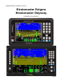
1
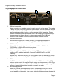
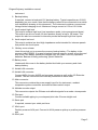
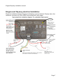
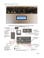
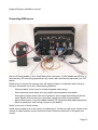
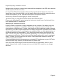
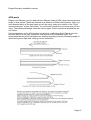
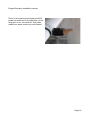
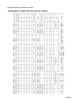
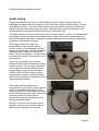
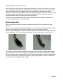
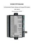
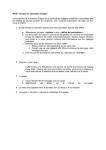
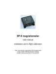
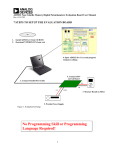
Enigma/Odyssey installation manual
Stratomaster Enigma
Stratomaster Odyssey
Installation documentation
Page 1
Enigma/Odyssey installation manual
Table of Contents
General...................................................................................................................................3
Enigma and Odyssey rear panel............................................................................................3
Connectors on Enigma and Odyssey................................................................................3
Odyssey specific connectors.............................................................................................4
Enigma and Odyssey electrical installation...........................................................................7
Installation tips:..............................................................................................................9
Typical RDAC connection................................................................................................11
Changing the backup battery...........................................................................................11
Preventing EMI issues.....................................................................................................13
AOA ports........................................................................................................................15
Ergonomic considerations...............................................................................................17
Transponder interface wiring...........................................................................................18
Transponder connections for popular models.................................................................19
Audio wiring..........................................................................................................................21
RCA connectors...................................................................................................................22
Page 2
Enigma/Odyssey installation manual
General
This document describes the installation requirements for a MGL Avionics Stratomaster
Enigma or Stratomaster Odyssey panel.
Both instrument types share similar installation requirements.
Enigma and Odyssey rear panel
Finding your way around the rear panel
Connectors on Enigma and Odyssey
1
1
4
3
2
5
6
19
17
11
7
20
10
16
21
22
18
15
8
9
12
13
14
Page 3
Enigma/Odyssey installation manual
Odyssey specific connectors
24
25
23
1. USB host connectors
These connectors are used to connect a master panel to a slave panel. The master
is always the host so the host connector of the master connects to the USB device
connector of the slave. Note: The connections you choose here determines which
panel is master and which is slave – no further setup for this is required. Please
note that some slave panel options may need to be setup in the instrument setup.
You can connect up to two slaves to a single master panel. The USB host
connector is also used to connect a communications extender module
1. USB device connector
This connector connects to a master panel or a PC application capable of
communicating with the instrument through USB such as flight simulators
2. RS232 Port 1
This multifunction port is typically used to connect NAV and COM radios or
XRX/PCAS or FLARM traffic monitoring systems.
3. RS232 Port 2 / NMEA
This port is a dedicated NMEA output containing GPS messages intended for your
autopilot or GPS enabled application. Baudrate is 4800 (Enigma) and 9600
(Odyssey).
Odyssey only: The RX of this port can receive NMEA from an external GPS if this is
selected in the instrument setup. External NMEA must be selected at 9600 baud.
4. GPS Antenna
This SMA connector accepts connection of an active GPS antenna. Active GPS
antennas contain a built in amplifier. Supply voltage on this connector is 3.3V. The
output is short circuit protected. A short circuit will switch off the supply voltage. The
instrument needs to be restarted to switch the supply on again.
5. Secured supply output
These two terminals provide power to AHRS, compass sensor, RDACs and IO
Extender. This power is switched to the battery backup (if fitted). Observe maximum
current capability of his output. Over current or shorting this output may damage the
Page 4
Enigma/Odyssey installation manual
instrument.
6. Backup battery
If required, connect a lead-acid 12V backup battery. Typical capacities are 2-5A/H
depending on your needs. Note that the battery needs to be connected via a switch
(see installation drawing in this document). The instrument contains a current and
voltage limited charging circuit. Maximum charge current is 0.5A at 13.8 Volts.
7. Audio output high level
This output contains high level, low impedance audio (voice prompts and alerts).
This output can drive a small 4-8 ohm speaker directly at up to 1W power. This
output can also be connected to intercom panels that accept high level inputs.
8. Audio output low level
This output contains low level high impedance audio intended for intercom panels
that provide low level inputs.
9. Battery cover release
Undo this nylock nut to remove the memory backup battery. The battery is the
common type CR2032. It is used to backup internal memory as well as run the real
time clock. This battery should be changed very two years. Use only reputable
batteries. Beware of badly performing “pirate” batteries.
10. Battery cover
Underneath this cover is the battery holder that holds your memory and clock
backup battery.
11. Airtalk LAN connector
12. Airtalk LAN connector
Connect MGL Avionics AHRS and compass sensors as well as the I/O Extender
module. The two connectors are internally connected to each other.
13. Main connector
This connector contains the power supply input for the instrument, ambient
temperature probe connection and external alarm switch output.
14. Altitude encoder output
This connector outputs the Gillman code altitude signals for a mode-c transponder.
15. Pitot port
Connect suitable piping to your airspeed pitot tube. Ensure airtight seal.
16. Static port
If required, connect your static port here.
17. AOA+ port
Positive pressure AOA port. Connect to AOA pressure pickup or positive pressure
port
18. AOA- port
Page 5
Enigma/Odyssey installation manual
Negative pressure AOA port. In case of single port AOA systems connect this to
static pressure. In case of dual (differential) AOA system, connect to negative
pressure port.
19. Rotor speed connector
In case of a rotor craft installation, this connector can be used to connect a rotor
speed sensor. The connector provides ground, signal and +12V output to supply a
sensor. The +12V output it connected to incoming supply power. Signal amplitude
is +5V with respect to ground minimum and may be up to supply voltage.
20. RDAC 1 connector
Connect a RDAC engine monitoring subsystem. This is the connection for RDAC 1,
the primary monitor or monitor number one in case of dual engine systems.
21. RDAC 2 connector
Connect a second RDAC monitor sub system for extended monitoring functions or
a second engine.
22. CAN/J1939 connector
This connection is used for the automotive CAN bus used by some engine
management systems.
23. ARINC-429 connector
Three RX (receive) and one TX (transmit) ARINC 429 channels are provided.
RX 1 and RX 3 are normal speed ARINC channels intended for connection to
ARINC enabled NAV and GPS receivers.
RX 2 is a high speed ARINC channel intended for connection of a ARINC 735
compliant traffic monitoring system (TCAS, TIS).
TX is a normal speed ARINC channel intended to connect to ARINC enabled
autopilots.
24. Analog NAV inputs
Four +/- 150mV differential analog inputs are provided to connect to NAV receivers
that provide compatible outputs.
Assignments are as follows:
Channel
Function
1
CDI (Course deviation indication)
2
GS (Glide slope indication)
3
CDI valid flag
4
GS valid flag
Page 6
Enigma/Odyssey installation manual
Enigma and Odyssey electrical installation
Electrical installation between Enigma and Odyssey is nearly identical. Odyssey has a few
additional connectors for CAN, ARINC and Analog NAV radio usage.
Page 7
Enigma/Odyssey installation manual
Odyssey rear panel
Page 8
Enigma/Odyssey installation manual
These images show basic wiring requirements for Enigma and the identical set for
Odyssey.
In this case a small backup battery is used. Note that two power switches are required.
One power switch for the main incoming 12 or 24 V feed (switch in positive supply lead),
another for the backup battery.
In flight, both switches would be “on” allowing the charging of the backup battery.
Preflight check would involve switching main power on, then battery power on. Check of
battery power would involve switching main power off and verifying that Enigma continues
to operate. Voltage on the backup battery should be measured by means of the backup
voltage readouts which can be placed on any display.
In this case the secured supply output is used to power a SP-3, 4 or SP-5 AHRS and/or a
SP-2 compass. This supply will draw from the backup battery in case of main power fail.
Please note that it is not permissible to connect other high current users to this supply
output. Maximum permitted current draw from these terminals is 0.5A. Under no
circumstances connect transceivers or lighting to these terminals.
Recommended backup battery types are 12V sealed lead acid with capacities ranging
from 1Ah to 2.5Ah for Enigma and 1.5Ah to 4Ah for Odyssey.
Usage of a backup battery is optional. It is not required for normal operation of the
instrument. The secured supply output may be used to supply AHRS and compass
sensors regardless of installation of a backup battery.
In case of a dual panel installation, it is permissible to connect both panels to a single
backup battery.
Please note that inline fuses or over-current sensing interrupters must be installed as
shown. It is wise to install these in such as way that it is possible to replace fuses in flight
or reset a circuit breaker.
Installation tips:
Avoid ground loops
If you are using MGL Avionics SP-2,3,4,5 sensors and have them connected to the
instrument via the RCA data cables, the ground connection from the secured supply output
should not be installed. The black ground wire from the SP sensors should remain
unconnected. The ground connection will be established via the RCA cable. A second
ground wire should not be used as this will create a possible ground loop resulting in
possible EMI problems.
If you are using data or signal cables between electrical instruments in your aircraft that
contain ground connections, always route these cables in such a way that no large ground
loops will be created. This can be achieved easily if cables like this are routed in tight
bundles with other ground connections. If you create a physical ground loop that has any
form of physically significant area (i.e. Two ground connections starting at one point, then
separating and finally merging at a second point), such a loop forms a loop antenna. This
can transmit small RF noise signals thatmay be present on the ground and cause radio
interference. At the same time, such a loop can act as effective receive antenna for your
radio transmissions and route the received signals into your electrical equipment. This can
Page 9
Enigma/Odyssey installation manual
cause feedback issues in radio/intercom systems and can result in disturbances to EFIS
systems.
Never share grounds.
Ground connections to backup battery, AHRS, compass and main supply to the instrument
must never be connected to each other or shared. These must remain individual
connections.
Avoid illegal ground currents
Ensure that all electrical users in your system have individual ground connections to a
central point, for example a ground connection bar to the aircrafts power supply negative
rail.
Some data or signal interconnections between instruments may require that these
instruments grounds are connected via the connecting data or signal cables. This creates
a potential problem that in severe cases can result in damage to your instruments.
Should one of your instruments loose its normal ground connection (for example a VHF
transceiver), it may use grounds through its signal or data cables through other
instruments. These ground connections may not be designed to allow large current flows.
In this example, should you press your PTT to start a transmission, a current of several
amperes may flow through the signal grounds causing potential damage.
Enigma and Odyssey contain electronic components in the signal and data ground lines
designed to block high frequencies to improve EMI performance. These components are
rated for a maximum DC current of 2 amperes. Should this current be exceeded, these
components may be damaged. Please note that damage to EMI components caused by
over current in ground connections is not covered by warranty. Please ensure that your
aircrafts electrical grounding system is sound and correctly designed.
Always separate RF systems and antenna cables
Radios and antenna cables may be powerful sources of interference to and from EFIS
systems. Always ensure that radios have their own grounds and power supply routing to
your aircrafts power system. Never share these connections with other equipment.
Never route antenna cables into wiring looms. Keep antenna cables separate from ALL
other wiring with some physical distance.
Never mount antenna cables close to the EFIS
Antennas may radiate significant amounts of RF power. If this is allowed to radiate into the
EFIS, malfunction may result. Note that any wires that are attached to the EFIS may route
received energy into the EFIS. Early signs of this are unstable altitude, airspeed and
vertical speed displays while you are transmitting on the radio.
In severe cases the EFIS may perform an emergency shutdown as operational parameters
may be exceeded.
Minimum distance of antenna to EFIS depends on many factors such as your antennas
radiation pattern, effects of your fuselage and output power of your radio.
Typical distances that should be considered are 6-9 ft, closer distances should be
Page 10
Enigma/Odyssey installation manual
evaluated on a case by case bases.
What to do with excess length of the GPS antenna cable
Should your GPS antenna cable be too long, loop the excess cable into a loop of abut 5-6”
diameter. Then flatten the loop leaving two loops at the end with about 1.5” diameter and
secure in this way using two or three cable ties. Flattening the loop avoids creating a
pickup loop for RF interference which may be routed to the EFIS via the antenna cable.
Image showing correct method to bundle excess cable length of the GPS Antenna
Typical RDAC connection
This image shows a typical RDAC wire connection. Ensure that the wires tips are correctly
stripped. We recommend that the wires be tinned using a soldering iron and electronic
solder wire (do not use acid flux).
Tighten the terminal screws but do not over-tighten.
These are special terminals containing friction locks
that prevent loosening under thermal changes and
vibration.
Changing the backup battery
Every two years, replace the backup battery. This is a type CR2032 as used often in
calculators. Obtain a replacement battery from a reputable manufacturer.
Have your new battery ready. Remove the old battery (push the clip downwards to release
the old battery, then insert the new battery by inserting into the top first and then pressing
down on the battery to clip it into position.
If you perform this within 1 minute you will not loose any data, however we recommend
that you copy your flight log and any routes that you may have stored on the internal RAM
drive to a SD card in case you do loose this data during the battery replacement.
Page 11
Enigma/Odyssey installation manual
Do not wait until the battrey is empty before replacing it.
Loosen this nut
An empty battery results in your instruments date and time
starting from 1. January at 00:00 every time you switch on
your instrument. Further to this, you will loose your
calculated fuel tank levels, accumulated fuel burn values,
flight log and routes.
Observe battery polarity as shown in this image
Lower this clip
to release battery
Page 12
Enigma/Odyssey installation manual
Preventing EMI issues
This image shows a photo of a typical, principle installation wiring on a MK-1 Enigma. Note
the use of ferrite beads on ALL wires leaving the instrument. Ferrite beads are effective to
eliminate any RF interfering signals that may cause radio interference particularly on VHF
radios.
Beads may or may not be required, this will depend highly on installation and routing of
wiring in the aircraft. As a rule, follow these guidelines:
•
Antenna cables must never be routed alongside other wiring.
•
Place antennas as far away from any digital instrumentation as possible.
•
Avoid ground loops which can act as powerful, short range transmitting aerials for
weak signals. Ensure that your aerial has a good and correct ground plane.
•
Never share power or ground cables between RF equipment and digital equipment.
Each requires their own routing of power to the battery.
Notes on the use of ferrite beads:
Install ferrite beads close to the source of interference. It does not help much if there is two
meters of cable between source and ferrite bead. Distances as shown in the photo are
correct.
Page 13
Enigma/Odyssey installation manual
Multiple wires may share a single ferrite bead with the exception of the GPS aerial antenna
which requires a ferrite on its own.
In case of the GPS aerial, loop the cable twice through the ferrite. Notice the size of the
loops. Never loop this cable tightly, you will greatly reduce the sensitivity and performance
of the GPS system if you do. The size of the loops in the photo is correct.
Other wiring should be looped tightly as shown in the photo.
The more loops you can place around a ferrite, the better the effect.
Please note again that ALL wires leaving the instrument should have a ferrite bead if you
have problems with RF interference.
Identifying RF interference sources:
Enigma creates a signal that is highly dependent on the contents of the display and may
sound like an “angry grrrrrr”. If you have radio noise, change the screens to see if the
noise pattern changes as well. If it does, start identifying which cables are used to transmit
the noise to your radio. Enigma itself does not transmit a significant signal due to strict EMI
design techniques however, small signals may readily leak and use any attached wires as
convenient antenna for transmission. Thus, remove the wires one by one. Start with the
GPS – this is a long wire and may contribute significantly. You can remove this wire with
the instrument switched on. Then try the audio and airtalk cables which can be unplugged
easily, This way you will quickly find the source. Place ferrites as needed or reroute the
cable to improve the situation.
A good installation should not generate any noticeable RF interference on your VHF radio
with the squelch fully opened, you should hear only static noise.
Note that inside metal hangers noise interference may be considerably worse in some
cases. Always check outside a hanger and move at least 100 ft away from any hanger
structure.
Page 14
Enigma/Odyssey installation manual
AOA ports
Enigma and Odyssey can be used with two different kinds of AOA measurement systems,
single or dual ported. These are referred to as Relative or Differential systems. Once you
have decided which of the port types you will be using, select your choice in the “Flight
instruments setup” of your instrument. You instrument needs to know which type you are
using. The following drawings show the various types. Exact mechanical dimensions are
not critical.
Correct operations of the AOA system is subject to a calibration flight. Please view the
relevant section in the user manual on how to perform the calibration flight. We
recommend that the AOA indications are checked regularly by briefly increasing angle of
attack during save flight and verifying correct indications.
Page 15
Enigma/Odyssey installation manual
Photo of an experimental single port AOA
probe mounted next to the pitot tube on the
wing strut of our Jora aircraft. This probe,
made from wood, works very well indeed.
Page 16
Enigma/Odyssey installation manual
Ergonomic considerations
Enigma and Odyssey contain very advanced LCD display that are able to perform well in
direct sunlight conditions. In order to achieve this and further ensure low power
consumption, the display contains a “light director”. This focuses the major part of
available light towards the viewer, creating a brighter image but also reducing the effect of
ambient light falling at an angle onto the display surface.
Odyssey is designed with a 0 to +40 degree viewing angle to favor traditional vertical
instrument panels.
Enigma is designed for optimum viewing angle of -30 to +25 degrees. In order to take
optimum advantage of this, the panel should be installed such that the pilots eye will look
onto the panel in a vertical -30 to +25 degree angle maximum. The negative angle would
be applicable for a steeply sloped panel where you would be looking onto the panel from
below.
This can be achieved in two ways: Mount the instrument as high as possible onto the
panel. This also aids the pilot as the image is closer to the windscreen avoiding eye fatigue
while constantly changing view from the panel to outside the aircraft.
If this is not possible or can only be done in a limited way, consider tilting the instrument up
slightly in order to aim the picture towards the pilot.
Idealized view of a sloped panel to optimize viewing quality. This image overdoes this
somewhat, in practice the panel does not have to be angled this much and if it is possible
to install the instrument relatively high on the panel, it is not normally required to mount the
instrument angled.
Preferred horizontal viewing angles are within left 50 degrees to right 50 degrees. If a
single instrument is to be shared between two pilots seated side by side, consider
installation of the instrument towards the center of the panel or alternatively angle it
towards the disadvantaged side somewhat. The panel can be read as angles greater than
Page 17
Enigma/Odyssey installation manual
+/-50 degrees but with reduced brightness.
Transponder interface wiring
The transponder interface produces Gillman (Gray) coded altitude information suitable for
connection to a mode C transponder.
Connections using the standard code identifiers are shown here. If your transponder does
not support signals D4 and D2, leave them unconnected. At least one of the ground wires
should be connected to the corresponding ground terminal of your transponder.
Page 18
Enigma/Odyssey installation manual
Page 19
Enigma/Odyssey installation manual
Transponder connections for popular models
Page 20
Enigma/Odyssey installation manual
Transponder interface wiring for Microair T2000 (ignore pin numbers on DB15 connector).
Also line “Encoder power” is not used with Enigma.
Page 21
Enigma/Odyssey installation manual
Audio wiring
Enigma and Odyssey provide two related audio outputs. These outputs carry voice
messages and alerts and other signals. One of the audio outputs is able to drive a small
loud speaker directly. The other output caries a low level signal intended to be fed into
intercom systems that have a low level input. The high level output can often be used
directly with intercom systems that provide high level inputs only.
The audio outputs are not provided with internal volume control or mute. It is intended that
mute and/or volume controls are provided either as part of the audio intercom panel or
they can be easily added with components easily obtainable from electronic parts shops
as shown in the following images:
This image shows the usage of a
potentiometer to be used as volume
control. Here it is used plugged into the
high level audio output. If a low resistance
potentiometer is used (for example 50
ohms, 1W power capable), it can be used
to control the volume of an attached 4 or 8
ohm speaker.
If you are connecting to an intercom
system or audio panel that does not allow
volume control, you can likely use higher
value resistance potentiometers but we
recommend no to go larger than about
1KOhm (1000 Ohms) in order to keep
impedances low which makes the audio
system more resistant to interference from
other electrical systems.
This image shows an alternative
arrangement if you want to install a panel
switch to mute the audio signal. In this
case a small SPDT switch has been used.
In the muted position the audio input of the
intercom system or audio panel is
connected to ground (shorted) to avoid
pickup of electrical noise.
Should you want to use a switch with a
speaker, you can use a simple switch to
disconnect the speaker as required.
Page 22
Enigma/Odyssey installation manual
Both of the above image show a suggested installation of a small ring ferrite in the audio
line. Ferrites provide a RF block for high frequency signals received on the cables from
radio transmissions. These signals can cause interference in particular with audio
systems. It is advisable to loop the cable a few times through the ferrite as shown. Ferrites
are obtainable from electronics shops. Ensure that the ferrite is suitable for the high
frequencies used with VHF radios such as NiZn ferrites,
Ferrites may be required particularly in tight installations where radios, antennas and
sensitive equipment are in close proximity.
RCA connectors
RCA connectors are used for audio connections as well as for the Airtalk local area
network.
We recommend that good quality plugs/cables are used. Poor quality plugs may not seat
tightly and may dislodge. Poor quality cables may give intermittent contacts.
Good quality RCA plugs and cables can be obtained from vendors that provide audio and
video equipment. Do not buy expensive cables – these will not give you any benefit.
Two types of common RCA connectors. The type on the left tends to have poor holding
power and may need to be secured from departing the RCA socket in flight. Some types
like this can be improved by bending the four tabs slight inwards to improve holding power.
The type on the right is generally much better giving a tight and firm fit that is unlikely to
loosen itself from the RCA socket in flight.
Page 23