1
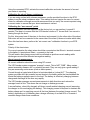
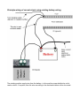
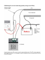
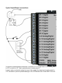
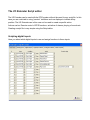
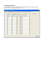
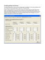
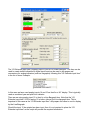
Airtalk I/O Extender
for Stratomaster Enigma, Odyssey and Voyager EFIS systems
User manual
Document date 21/6/2007
General
The I/O Extender is a small unit designed to extend the I/O interface capabilities of an EFIS
(Electronic Flight Instrumentation System).
This unit interfaces to airtalk compatible systems and operates from a local power supply of
12V nominal. The unit may be operated between 8V and 18V DC voltage levels indefinite.
I/O functions
The I/O Extender provides the following functions:
Digital inputs
Up to 19 digital inputs can be utilized. Each input reads “low” if a voltage of less than 1.5V is
applied and “high” if a voltage of more than 3V is applied. Each input has a built in hysteresis
to avoid undefined states during signal transition. Each input is protected against voltage
surges and filtered against the effects of RF. Each input is tolerant of voltages up to +20V.
All inputs are weakly connected to ground (zero volt) level using approximately 15KOhm of
resistance. Inputs left unconnected return a “low” level.
Inputs 1-8 are multiplexed with outputs 1-8. These lines may be used either as inputs or
outputs. If used as outputs, reading the input will return the current value of the output.
Inputs 9-15 are multiplexed with analog inputs. These inputs may be used as digital inputs
regardless if the analog inputs are used as well.
Inputs 16-19 or digital inputs only.
Using the I/O Extender script editor, it is possible to configure inputs 16-19 to create alarms
on the EFIS instrument. Alarms can be activated either as “low level” or “high level” active.
Inputs may also be used to prompt voice messages using the EFIS sound system.
Typical uses for digital inputs:
Flap position, gear position, door and hatch open/closed contacts, liquid level switches,
Remote control of EFIS functions.
Digital outputs
Up to 8 digital outputs are available. These outputs are all open collector power transistors
switching to ground (zero volt) level. The output is either off “high impedance” or on “low
impedance current path to ground”. If the output is “off” the input that is associated with this
output can be used as free digital input. It is also possible to use the input to report on the
voltage level (on or off) at the output. This may be useful in some applications to provide
feedback on a switching process.
Outputs may switch up to 0.5A of current. In case inductive loads are to be switched (such as
relays or solenoids) a clamp terminal if provided to shunt the back-EMF created by the
inductive load when the transistor is turned off. The clamp terminal must be connected to the
12V supply rail. If no inductive loads are switched, the clamp terminal may be left
unconnected.
Failing to connect the clamp terminal correctly in case inductive loads are switched can
destroy the output transistor or severely affect the operation of the I/O extender negatively.
Outputs may be connected to groups of alarms for alarm annunciator panels or may be used
in connection with analog inputs in a form of automation. For example, using the I/O Extender
script editor you can program a certain analog input level to control a digital output.
When a I/O Extender powers up, all outputs are “off” by default and the inputs can be used.
Only events actioned by the I/O Extender script (if installed) can switch an output “on”.
Analog inputs
Up to 7 analog inputs are provided. These inputs are scaled to allow measurement of voltage
levels in the range of zero volts (ground level) to +13.8 volts.
If the input is at zero volts, a value of “0” is measured. If the input is at 13.8V, then a value of
“1023” is returned. Values higher than 13.8V will return 1023.
Analog inputs can be used as sources for EFIS analog displays such as bargraphs etc.
The first four analog inputs (labeled input 9-12) can be set up to create EFIS alarms using the
normal instrument alarm setup and routing system
All analog inputs can be scaled to provide a meaningful readout.
Typical uses for analog inputs:
Trim and flap position indicators. Control surface position indicators. Liquid levels (fuel or oil
tank levels). Pressure sensor readings.
Current monitoring
The I/O Extender provides a bi-directional current monitoring system. This is intended to
measure the charge and discharge currents to and from the aircraft battery.
Current is measured indirectly by measuring the small voltage drop created by current flowing
through a suitable shunt resistor. Typical shunt resistors are in the range of 0.010 ohm (10
milli-ohm) to 30 milli ohm. However, the current measuring system has been designed to
accept any shunt. In particular, you can usually use the +12V supply cable from the battery +
terminal to the power distribution system as a suitable shunt. Connect the I/O Extender shunt
terminals using two wires (these can be thin wires) to each side of the cable connecting the
battery + terminal to the current distribution system.
In this scheme, large, temporary current users such as electrical starter motors should NOT
be routed through the shunt. These should be wired directly to the battery via their starter
solenoids using adequately dimensioned cable.
Calibrating the shunt (known current):
The I/O Extender needs to know the resistance of the shunt in order to correctly calculate the
current flowing through it.
Our suggested method involves using a cheap digital or analog multimeter (they tend to have
a 10A DC range). Wire this meter in series with the shunt and switch some electrical users on
so you have a reasonable current flow (for example 2 – 4 A). Do not run the engine or have
any charging active for this calibration.
Using the connected EFIS, activate the current calibration and enter the amount of current
your meter is reporting.
Calibrating the shunt (known resistance):
If you are using a shunt with a known resistance, use the provided functions in the EFIS
system to set the shunt resistance value. This method does not require the use of a current
meter for calibration although we would recommend that you verify the current reported using
a current meter to ensure that your shunt resistance is correct.
Calibrating the “zero current” point.
This is a calibration that has happened at the factory but you can perform it yourself if
needed. The idea is to ensure that the I/O Extender returns a “0” current flow if no current is
flowing through the shunt.
For this, disconnect one of the wires to the shunt and connect it to the other side of the shunt.
Both wires will not be connected to the same side of the shunt (it does not matter which side).
Once this has been done, perform the “set current zero” calibration function in your EFIS
system.
Polarity of the shunt wires:
For correct operation the shunt wires should be connected so that Shunt + terminal connects
to the battery + terminal and Shunt – connects to the load.
This will ensure that charge current with be reflected as positive current reading while
discharge current will be reflected as negative reading.
About current measurement:
All current calibration should be done using DC current.
The I/O Extender system measures “average” current. This is NOT “RMS”. Many meters
cannot accurately measure A/C or pulsating currents. They can only give a good reading if
they are measuring a sine-wave (such as mains power).
Current through a typical aircraft shunt is best described as “pulsed A/C”. The charging
system provides short but powerful current bursts to the battery while the time between the
bursts the battery supplies current to the load. The battery is effectively changing between
charge and discharge all the time very rapidly.
The I/O Extender averages current measurements in both directions and returns the
averaged result of this. This shows the net charge or discharge current.
A normal battery, when fully charged, will show a small residual charging current (assuming
the charger is not overcharging the battery). This charging current is required to maintain the
battery charge as it is supplying current all the time (between the pulsed charge current). The
battery, depending on its chemistry has a charge efficiency of around 80% so it needs a
constant charge under these conditions.
Principle wiring of current shunt using existing battery wiring
The existing positive supply wire from the battery + to the positive power distribution rail is
used as shunt. If required, size this wire according to the resistance tables in this document.
Calibrating the current measuring system (using current flow)
A current meter set to DC current is wired in series with the shunt. The DC current measured
(with engine switched off / no charging) is used to calibrate the shunt using provided functions
in the EFIS system.
Typical Input/Output connections
This picture shows example connections. We wired a 12V/1W light bulb to I/O 1, a relay coil
to I/O 2, a switch to I/O 7 and a potentiometer to analog input 9.
In case a relay or solenoid is wired into one of the outputs the clamp input must be wired to
+12V as shown to prevent possible damage to the I/O Extender due to back-EMF of the coil.
The I/O Extender Script editor
The I/O Extender can be used with the EFIS system without the need for any script file. In this
case you are restricted to using “passive” indicators such as displays to indicate a flap
position. The I/O Extender can is this case not be used to create a specific action.
Actions can be: Remote control of EFIS functions, activation of alarms, playing of sounds etc.
Creating a script file is very simple using the Script editor.
Scripting digital inputs
Here you select which digital inputs to use and assign functions to these inputs
Scripting analog inputs
This script allows you to use analog inputs in a form of automation. For example you may
want to switch on a fuel pump if a tank level is low.
Scripting digital outputs
This script allows you to switch digital outputs as a result of EFIS alarms. This is useful if you
would like to create an alarm annunciator panel. Note that there is a remote alarm
acknowledge function provided a s part of the digital inputs scripting.
Scripting digital input alarms
This script allows to to connect up to four digital inputs (inputs 16 to 19) to EFIS alarms that
follow the normal alarm setup and routing rules.
Scripting analog level alarms
This script allows you to use up to four analog inputs in bargaph or other analog displays that
are connected to instrument alarms. Inputs 9 to 12 can be used.
Passive analog channels (not connected to alarms) are defined as part of the EFIS screen
setup. If an analog input is required to be connected to the instruments alarm system, you
define the display parameters and limits here. The reason for this is that the EFIS instrument
needs to know these settings even if the corresponding display item (bargraph etc) is not
visible on the screen or non has been defined.
Creating the script file
Once you have set up your desired inputs and outputs, use this screen to create your script
file. The file is called “IOEX.ESF”.
To try out the file in the EFIS simulator, copy the file to the “Flash” folder of the currently
active project or alternatively copy the file to the “mmc” folder of your EFIS simulator and
install the file using the “Install IOEX script file” function in the “common tasks” menu.
To use the script file on the actual EFIS, copy the script file to your SD card and insert into the
EFIS. Then use the “Install IOEX script file” function in the common tasks menu.
Using the I/O Extender as remote control for the EFIS
It is possible to connect a few external push buttons to the I/O extender and use these to
control certain functions on the EFIS. For this you need either three or four push buttons
(sometimes these can be mounted into a joystick).
Using the Script editor, assign the inputs used to your push buttons. You need one button to
select/deselect the remote menu. One button to select a function in the menu. One button to
move forward in the menu and an optional button to move backwards in the menu.
Example image of an Enigma system with the “Remote control” menu activated via the I/O
Extender.
Using the I/O Extender with EFIS display components and
alarms.
The I/O Extender inputs can be used with the “I/O Extender Input” item in your EFIS screen
designer.
Digital and analog inputs can be used in one of two modes: Active or Passive. Passive
indicators are the easiest to use as they do not require a script (See script editor description
in this document).
Place the “I/O Extender input item” before any analog displays that will be using the input that
you specify in the item. Digital displays are defined directly in this item (round or rectangular
indicators). Analog items (bargraphs, analog arcs etc) are used indirectly: You specify the
ranges and conversions required and any analog indicator appearing in the list of items after
the “I/O Extender input item” can use these settings.
If you want to use digital or analog inputs with the EFIS alarm system, they become “active”
items. In this case you cannot use the “I/O Extender input item” to specify the ranges and
conversions for your signals. The reason for this is that the EFIS needs to know about your
settings even if no related screen items are used or visible. In this case you specify the
ranges and limits as part of the I/O Extender script.
The “I/O Extender input item” property editor in your EFIS screen designer. This item can be
used to create visible indicators for digital inputs and can be used to set ranges and
conversions for analog indicators (such as bargraphs) following this “I/O Extender input item”
in the list of items. Example:
In this case we have used analog inputs 14 and 15 as feed for a X/Y display. This is typically
used as combined yaw and pitch trim indicator.
Then we are using analog input 12 to feed to a Line Bargraph item. Note that the “I/O
Extender input item” I/O Ext analog 12 is before (above) the Line bargraph item. This is
important in this case as the “I/O Extender input item” will prepare the value to use for display
by the Line Bargraph.
Should the input 12 be scripted as alarm input, then it is not required to place the “I/O
Extender input item” as the script will provide the required information.
Using RDAC units as “I/O Extender”
It is possible to use the CHT1, CHT2, OIL Temperature and OIL Pressure inputs of any
RDAC unit as I/O Extender. This is available under the following conditions:
a) You do not have an I/O Extender connected.
b) The RDAC is wired to instrument input RDAC 2 (Engine 2)
c) The system is set up as “Dual RDAC” and “Single Engine” mode.
In this case, you can use the CHT1, CHT2, Oil Temperature and Oil Pressure inputs as you
would normally, but they are also connected to the I/O Extender system. There is no further
setup required to enable this feature. Effectively the normal RDAC modes and the I/O
Extender are both connected at the same time.
CHT1 is connected to Digital input 16 and Analog input 9
CHT2 is connected to Digital input 17 and Analog input 10
Oil Temperature is connected to Digital input 18 and Analog input 11
Oil Pressure is connected to Digital input 19 and Analog input 12
If you would like to use these inputs as “I/O Extender”, ensure that you have the four inputs
disabled from the instrument alarm system (RDAC 2 CHT1 to RDAC 2 Oil Pressure alarm
setup and routing).
Because of the way the RDAC inputs have been mapped to the I/O Extender, each of the
inputs can be used with the I/O Extender script. You can use these inputs to create digital or
analog input alarms and displays.
Please note that the RDAC input ranges are from 0 to 5V only. Do not connect to 12V or
higher voltages. All inputs are internally pulled up to 5V level using resistors. This means that
an unconnected RDAC input will return a “high” level (The I/O Extender would return a “low”
level in this case as it has pull down resistors).
Resistance and current tables for standard copper wire.
AWG
Feet/Ohm
Ohms/100ft
Ampacity*
mm^2
10
12
14
16
18
20
22
24
26
28
490.2
308.7
193.8
122.3
76.8
48.1
30.3
19.1
12.0
7.55
.204
.324
.516
.818
1.30
2.08
3.30
5.24
8.32
13.2
30
20
15
10
5
3.3
2.1
1.3
0.8
0.5
2.588
2.053
1.628
1.291
1.024
0.812
0.644
0.511
0.405
0.321
Meters/Ohm
149.5
94.1
59.1
37.3
23.4
14.7
9.24
5.82
3.66
2.30
Ohms/100M
.669
1.06
1.69
2.68
4.27
6.82
10.8
17.2
27.3
43.4
The above table can be used to create a shunt using standard copper cable.
For example, assume you want to use a AWG 14 cable and you need a shunt resistance of
10 milli-ohm (0.010 ohm).
From the table we can see that 59.1 meters of this cable would give us 1.0 Ohms resistance.
As we need only 100th of this value, we need 59.1 cm of this cable to give us our desired
resistance. This is a perfectly reasonable length of cable for most installations.
Please note: Due to manufacturing tolerances assume a possible error of up to 30% so if you
use this method to make yourself a shunt, it is a good idea to verify the reported current using
a separate current meter.
In the above table “ampacity” refers to the amount of average current the cable may carry for
a minor increase in temperature. For example, with AWG 12 at 20 amps current, you would
be converting approximately 0.2 watts of energy over a 1 meter (3.3 ft) length of this cable
into heat.