1
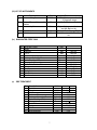
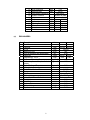
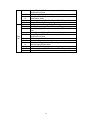
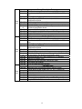
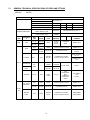
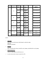
TECHNICAL SPECIFICATION FOR INTEGRATED PURIFIED WATER SYSTEM FOR LABORATORY INDEX S. NO. SUB HEAD PAGE NO. 1 SCOPE OF WORK 2 2 3 3 TECHNICAL SPECIFICATION FOR INTEGRATED PURIFIED WATERSYSTEM FOR LABORATORY TECHNICAL SPECIFICATIONS 4 LIST OF INDICATIVE MAKES 12 5 DRAWINGS AND DATA 12 6 GENERAL GUIDELINES FOR PIPING 13 7 GENERAL TECHNICAL SPECIFICATION OF PIPES AND FITTINGS 18 1 6 1.0 SCOPE OF WORK The scope of work includes design, supply, installation/ erection, testing & successful commissioning and handing over to CDRI the complete Integrated Purified Water System for Laboratory on item rate contract. The work shall be executed as per specifications and applicable standards. These specifications shall be read in conjunction with the General Conditions of Contract, Additional Conditions of Contract and BOQ. Power supply of 3 phase, 415 Volts, 50 Hz, AC shall be provided at one point by EPI / CDRI for group testing & commissioning of complete Integrated Purified Water System after erection is completed. However, the contractor shall make his own arrangements for power required during construction, fabrication, erection & trial run etc. 2 2.0 TECHNICAL SPECIFICATIONS OF INTEGRATED PURIFIED WATER SYSTEM FOR LABORATORY 2.1 GENERAL For the new upcoming facility of CDRI at Sitapur Road, Lucknow, the laboratories are being built and infrastructure being completed. With regards to utility requirement, the integrated purified water system shall be used for analysis in CDRI New Campus. This water shall be used in three sections of the labs namely Chemical, Pre-clinical and Molecular Biology. The water source at CDRI site is from bore well. The water quality needed by CDRI for analysis in their laboratories is equivalent to single distilled purified water. The water quality required by Chemical section is as per ‘Laboratory Water Type III’. This is in accordance with ASTM D1193 -91. This system is specially designed to meet CDRI water quality requirements. The integrated purified water system is required to meet CDRI’s water quality requirements and to produce consistent quality of water through out the life of the system. 2.2 SYSTEM DESCRIPTION Water is utilized for washing, preparation of lab units for operations, for preparation of distilled water and purified water (ultra-pure water). The water system comprises of feed pump with ion exchange system. This ion exchange system in turn comprises of dual media filter, activated carbon bed, cation exchanger, anion exchanger and mixed bed polisher. This treated water is then sent to a storage tank through a 40 micron filter. This tank is made of stainless steel construction with recirculation pump. The user points are then feed from the discharge of the storage tank downstream of the pump. This water shall be kept under continuous re-circulation as the water cannot be stagnant for more than 2 hours. Water quality as per Chemical section is as per ‘Laboratory Water Type III’. This is in accordance with ASTM D1193–91. Purified Water Generation Plant shall have 1 no. main Reservoir of 4000 Ltrs Capacity. Purified Water Generation Plant is located at Ground Floor with main reservoir Tank. Thereafter, the purified water shall be pumped to each floor of each Building / Laboratory having one user point in each lab. All piping, Valves and fitting shall be of SS 316 of internally electro polished grade only. Welding shall be Argon TIG Welding method from Qualified Welder. Piping size for main header shall be 1.0” and tapping header of ½” size of SS 316 Material with inside electro polished along with all fitting and valves etc. Capacity of Purified Water plant shall be 300 LPH with Operation ON AS REQUIRED basis. System shall be fully automatic with instrumentation like Pressure Gauges, Water Flow Meter with totalizer, Conductivity meter and Level Controller and pH indicator. Maximum operating working Pressure of Plant shall be 4 Bars. Valves shall be Ball Valves type for floor Isolation and Loop Valves for point of use make of reputed make. Design details of each equipment / instruments etc shall be as indicated in next section. The system shall be an in-built auto-dumping facility in case the temperature and/or conductivity of the feed water do not meet the required quality parameters. Pressure switches shall be mounted on all the incoming process lines for monitoring the supply utilities. In case of a pressure drop or non-availability of utilities, an alarm shall be generated. Two conductivity sensors shall be provided in the feed water and treated 3 water lines. The conductivity sensor shall be connected to an analyzer cum transmitter to generate a 4-20mA input to the PLC. The control cabinet shall be provided with a main isolator for the three-phase supply and a separate switch for the control supply. All cabling shall be flexible, PVC cabling routed via PVC channels mounted in the panel. All cabling for temperature and conductivity signals shall be shielded for minimum electro-magnetic interference. Necessary relays, contactors, MCB’s, etc. shall also be mounted in the control panel. The service and maintenance area is provided with a lighting fixture, plug, and socket. The control system shall be provided with manual back up in case of PLC failure. Here all valves, pumps, etc. can be operated via switches. 2.3 OPERATION PRINCIPLE OF THE WATER SYSTEM. The water from central storage (raw water tank) shall be pumped to first section of the integrated purified water system i.e. the ion exchange treatment system. The water shall be treated to remove any coarse solids using the dual media filter. The water is then treated in series to remove any odours /colours and any organic content using activated carbon filter. The water free from coarse solids, odours, colours and organic content is processed in cation exchanger bed followed by anion exchanger bed to remove TDS. The treated water is then polished through a mixed bed polisher. The purified water shall be filtered through a 40 micron filter to ensure no carry over from ion exchange system. The water after treatment shall be then directed to stage 2 of IPWS i.e. the storage tank and distribution system. This water shall be kept under continuous re-circulation as the water cannot be stagnant for more than 2 hours. Consequently, this water will be used at user locations. 2.4 PROCESS DATASHEET & DETAILED TECHNICAL SPECIFICATION a) Process Datasheet • Water usage per day o 10 Ltrs per Lab per day X 8 Labs per Floor X 3 floors per building X 6 buildings o 1440 Liters per day o 1 Point in each Room near Wash Basin • Operating flow rate o 240 LPH o 5.76 m3/day • Design Flow Rate o 300 LPH o 7.2 m3/day • Main Tank Capacity o Measured volume o Available volume : : 4400 liters 4000 liters 4 • Piping Requirement o SS 316 with internal electro – polish • Mode of Operation o Fully Automatic (including regeneration) AUTO-DUMPING FACILITY The system has an in-built auto-dumping facility in case the temperature and / or conductivity of the feed water does not meet the required quality parameters. PRESSURE SENSORS Pressure switches are mounted on all the incoming process lines for monitoring the supply utilities. In case of a pressure drop or non-availability of utilities, an alarm is generated. CONDUCTIVITY SENSORS Two conductivity sensors are provided in the feed water and treated water lines. The conductivity sensor is connected to an analyzer cum transmitter to generate a 4-20mA input to the PLC. ELECTRICAL SWITCH GEAR The control cabinet is to be provided with a main isolator (MCCB) for the three-phase supply and a separate switch for the control supply. All cabling is flexible, PVC cabling routed via PVC channels mounted in the panel. All cabling for temperature and conductivity signals is shielded for minimum electro-magnetic interference. Necessary relays, contactors, MCCB’s, etc. are also mounted in the control panel. The service and maintenance area is provided with a lighting fixture, plug, and socket. Thickness of Sheet steel shall be 2mm CRCA minimum . Control wiring shall be done with 2.5 mm2 flexible stranded copper wire & for PLC wiring, it shall be 1.0 mm2. Minimum rating of contractor shall be 25A Aluminum Busbar with Heat Shrinkable Sleeve shall be provided. Busbar density shall be .8A /Sq mm for Aluminum. Degree of protection shall be IP54. MANUAL BACK-UP The control system is provided with manual back up in case of PLC failure. Here all valves, pumps, etc. can be operated via switches. SAFETY AND ALARMS The process management system is provided with a series of safety and alarm features:• Utility failure alarm. • Feed Water Conductivity high. • Feed pump trip. PROCESS RECORDING Colour inkjet A4 printer for recording – date, time, process parameters, process status, alarms etc 5 FACTORY ACCEPTANCE TEST After manufacture and in-house testing the machine shall be offered for customer inspection and testing as per in-house FAT protocol. The Protocol can be reviewed jointly and suitably amended within the limit of the code, if necessary prior to the schedule test runs. APPROVAL OF DOCUMENTS The following documents shall be submitted by the successful bidder for approval: 3 Maintenance and service manual. Design Document. Installation Document. Operational Document. Testing and Calibration Reports. Layout for plant TECHNICAL SPECIFICATIONS (i) Details of Integrated Purified Water System: No 1. 2. 3. 4. 5. 6. (ii) Description Source of the Water Raw Water Inlet Ionic load on each exchanger Operation of plant Per day operation Plant flow Plant output between two regenerations Bore Well Water 100.00 ppm Automatic 8.00 hrs. 500 lit/hr. 10.0 3 LIST OF EQUIPMENTS No 1. 2. 3. 4. 5. 6. 7. 8. 9. 10. 11. 12. 13. 14. Description Raw water Feed tank Dosing Tank Chemical Tank Feed Pump Dual Media Filter Activated Carbon Filter Cation Exchanger Anion Exchanger Mix Bed Polisher Cartridge Filter Purified water storage tank Purified water pump Electrical Panel Interconnecting Pipe Line Qty Remarks 1.00 1500 liters 1.00 20 liters 1.00 25 liters 2.00 1 working + 1 stand by 1.00 500 lit/hr. 1.00 500 lit/hr. 1.00 500 lit/hr. 10 m3 OBR 1.00 500 lit /hr. 10 m3 OBR 1.00 500 lit /hr. 10 m3 OBR 2.00 1 working + 1 stand by 1.00 1000 liters 2.00 1 working + 1 stand by 1.00 Pump starters and instruments 1.00 Feed Water Pump → DMF → ACF → SAC → SBA→MB 6 (iii) LIST OF INSTRUMENTS No 1. Description Pressure Gauges 3. Water Flow Meter totalizer Conductivity Meter 4. 5. Level Controller pH Indicator 2. Qty 7.00 nos with 1.00 no 2.00 nos 1.00 no 1.00 no Remarks 2½” Dial Bottom connection 0 – 10 kgs/cm2 range At Mix Bed Polisher Out let Digital field mounted Anion and Mix Bed out let Treated Water Storage Tank Field Mounted at Mix Bed Out let (iv) RAW WATER FEED TANK NO 1. 2. 3. 4. 5. 6. 7. 8. 9. 10. 11. 12. 13. (v) DESCRIPTIONS Model Diameter HOS Maximum Capacity Maximum Operating Pressure Hydro Testing of Pressure Material of construction Shell, Dish, Strainer Plate Piping Gasket Shell thickness Dish Thickness Pipe line size UNIT MM MM Liters Kgs/cm2 Kgs/cm2 1000.00 1500.00 1000 4.00 6.00 MM MM NB SS 316 SS 316 Natural Rubber 5.00 5.00 20.00 PRE TREATMENT No 1. 2. 3. 4. 5. 6. 7. 8. 9. 10. 11. Descriptions Unit Model Diameter MM 250.00 250.00 HOS MM 1800.00 Maximum Flow Lit/hr. 500 Maximum Operating Pressure Kgs/cm2 4.00 Hydro Testing of Pressure Kgs/cm2 6.00 Material of construction Shell, Dish IS 2062 Piping SS 304 Gasket Natural Rubber Shell thickness MM 5.00 7 12. 13. 14. 15. 16. 17. 18. 19. 20. 21. 22. (vi) Dish Thickness Pipe line size Inlet Water Distribution Water Collection Media Carbon Anthracite Filtering Sand Silex Gravels Pebbles MM NB MM MM MM MM MM MM 6.00 20.00 Bell Mouth Strainer on plate 900.00 300.00 300.00 100.00 300.00 75.00 75.00 300.00 EXCHANGERS No 1. 2. 3. 4. 5. 6. 7. 8. 9. 10. 11. 12. 13. 14. 15. 16. 17. 18. 19. 20. 21. Descriptions Unit Model Diameter MM 300.00 300.00 HOS MM 1500.00 Maximum Flow Lit/hr. 500 Out Put Between two regeneration M3 10.00 Resin Qty Liters 60.00 60.00 Regnrant qty. 100% Kgs 4.25 4.80 Maximum Operating Pressure Kgs/cm2 4.00 Minimum pressure require for brine Kgs/cm2 1.50 ejector Hydro Testing of Pressure Kgs/cm2 6.00 Material of construction Shell, Dish, Strainer Plate IS 2062 Piping SS 316 Gasket Natural Rubber Rubber Lining IS 4682 Part I Water Distribution / Collection Strainer on Plate Shell thickness MM 5.00 Dish Thickness MM 5.00 Strainer Plate MM 8.00 Rubber Lining MM 3.00 Pipe line size NB 20.00 8 (vii) MIX BED POLISHER No 1. 2. 3. 4. 5. Descriptions Model Diameter HOS Maximum Flow Out Put Between two regeneration Unit MM MM Lit/hr. M3 6. Resin Qty Liters 7. Regenerant qty. 100% Kgs 300.00 1600.00 500 10.00 15.00 25.00 1.05 2.00 4.00 1.50 6.00 8. Maximum Operating Pressure Kgs/cm2 9. Minimum pressure require for brine ejector Kgs/cm2 10. Hydro Testing of Pressure Kgs/cm2 11. Material of construction 12. Shell, Dish, Strainer Plate IS 2062 13. Piping SS 316 14. Gasket Natural Rubber 15. Rubber Lining IS 4682 Part I 16. Water Distribution / Collection Strainer on Plate 17. Shell thickness MM 5.00 18. Dish Thickness MM 5.00 19. Strainer Plate MM 8.00 20. Rubber Lining MM 3.00 21. Pipe line size NB 20.00 (viii) CARTRIDGE FILTER NO 1. 2. 3. 4. 5. 6. 7. 8. 9. 10. 11. 12. 13. 14. 15. DESCRIPTIONS Model Diameter HOS Maximum Flow Maximum Operating Pressure Hydro Testing of Pressure Material of construction Shell, Dish, Strainer Plate Piping Gasket Shell thickness Dish Thickness Pipe line size Filter Cartridge (1 per vessel) Filter cartridge (dimension : OD X Length) 9 UNIT MM MM Lit/hr. Kgs/cm2 Kgs/cm2 MM MM NB Nos. mm 200.00 800.00 500 4.00 6.00 SS 316 SS 316 Natural Rubber 5.00 5.00 20.00 2.00 150 500 (ix) FEED PUMP NO 1. 2. 3. 4. 5. 6. (x) DESCRIPTIONS Normal Flow rate Head Maximum Flow Maximum Operating Pressure Hydro Testing of Pressure Material of construction (contact parts) UNIT Lit/hr. kg/cm2.g Lit/hr. kg/cm2.g kg/cm2.g 300 4.0 500 4.00 6.00 CAST STEEL RECIRCULATING PUMP NO 1. 2. 3. 4. 5. 6. DESCRIPTIONS Normal Flow rate Head Maximum Flow Maximum Operating Pressure Hydro Testing of Pressure Material of construction (contact parts) UNIT Lit/hr. kg/cm2.g Lit/hr. kg/cm2.g kg/cm2.g 300 4.0 500 4.00 6.00 SS316 BILL OF QUANTITIES One set Two Nos Two Nos Two Nos Two Nos One No One No One set One set One No One No One Lot of One No One No One No Raw Water Feed Pump assembly Raw Water Pump Mono block constructed Suction strainers Y type Suction Isolation Valve Outlet Isolation Valve Pressure Indicators Installed on common header Dual Media Filter Mild Steel constructed vertical Pressure Vessel Vessel Internally Anti corrosive Painted Vessel Externally Epoxy Painted Frontal Pipe line SS 304 constructed, suitable for Multifunctional Valve Multifunctional Valve Assembly Initial fill of Filter Media as mentioned in the technical specification sheet Pressure Indicator (2½” Dial, Glycerin Fill 0-7 kgs/cm2) Sample SS Needle Valve Activated Carbon Filter Mild Steel constructed vertical Pressure Vessel Vessel Internally Anti corrosive Painted Vessel Externally Epoxy Painted 10 One No One No One Lot of One No One No One No One No One set One No One No One Lot of One No One No One No Frontal Pipe line SS 304 constructed, suitable for Multifunctional Valve Multifunctional Valve Assembly Initial fill of Filter Media as mentioned in the technical specification sheet Pressure Indicator (2½” Dial, Glycerin Fill 0-7 kgs/cm2) Sample SS Needle Valve Strong Cation Exchanger Mild Steel constructed vertical Pressure Vessel Vessel Internally Rubber lined as per IS 4682 Part I, 3.00 mm thick Vessel Externally Epoxy Painted Frontal Pipe line SS 316 constructed, suitable for Multifunctional Valve Multifunctional Valve Assembly Ejector for Regnrant suction Initial fill of Strong Cation H+ Resin. Qty as mentioned in the technical specification sheet Regeneration Tank Pressure Indicator (2½” Dial, Glycerin Fill 0-7 kgs/cm2) Sample SS Needle Valve 11 One No One No One set One No One No One Lot of One No One No One No One No One No One No One set One No Two Nos One Lot of One No One No One No One No One No Two Nos One set Two Nos Two Nos Four Nos Two Nos Two Nos Strong Base Anion Exchanger Mild Steel constructed vertical Pressure Vessel Vessel Internally Rubber lined as per IS 4682 Part I, 3.00 mm thick Vessel Externally Epoxy Painted Frontal Pipe line SS 316 constructed, suitable for Multifunctional Valve Multifunctional Valve Assembly Ejector for Regenerant suction Initial fill of Strong Anion Cl- Resin. Qty as mentioned in the Technical specification sheet Regeneration Tank Pressure Indicator (2½” Dial, Glycerin Fill 0-7 kgs/cm2) Sample SS Needle Valve Digital on line field mounted conductivity meter Mix Bed Polisher Mild Steel constructed vertical Pressure Vessel Vessel Internally Rubber lined as per IS 4682 Part I, 3.00 mm thick Vessel Externally Epoxy Painted Frontal Pipe line SS 316 constructed, suitable for Multifunctional Valve Multifunctional Valve Assembly Ejector for Regenerant suction Initial fill of Strong Cation H+ and Strong Anion Cl- Resin. Qty as mentioned in the technical specification sheet Pressure Indicator (2½” Dial, Glycerin Fill 0-7 kgs/cm2) Sample SS Needle Valve Digital on line field mounted conductivity meter Flow Meter with totaliser pH on line field mounted Indicator Cartridge Filter Stainless Steel constructed vertical Pressure Vessel Vessel design as per ASME SEC VIII, DIV 1 (Latest Ed.) Vessel Externally Epoxy Painted Vent valves Drain valves Isolation Valve Pressure Indicator (2½” Dial, Glycerin Fill 0-7 kgs/cm2) Sample SS Needle Valve 12 One No One Lot One No One No One No One no Common Mild Steel constructed, fabricated from ‘I’-channel skid Crca sheet steel constructed electrical panel PVC common drainage system Integrated Purified Water System out let isolation valve (PP constructed) SS 316 constructed cylindrical vertical type Integrated Purified Water System storage tank. 4.0 LIST OF INDICATIVE MAKES The following is the list of products and indicative makes. Bidder is free to propose any other equivalent Make meeting Technical Requirements, Specifications alongwith required details in support of the same. The same would be analyzed and accepted if found suitable after discussion between EPI and bidder. The Makes shall be finalized during Technical evaluation prior to opening of Price-Bids. Bidders are required to offer reputed equipment / component which is strictly meeting technical requirements, enclosed specifications alongwith NIT and other relevant / latest applicable Standards & Rules. No 1. 2. 3. 4. 5. 6. 7. Description DM Plant Resin Anti Rust (X-ceed 520TM) Pressure Gauge Valves Raw Water/Recirculation Pumps Instruments 8. 9. SS 316 pipes Cartridge Filter Indicative Makes Thermax/ ION Exchange/Siemens Auctel / Thermax / ION Exchange Eximious / Shreeyantra Mass / Precision / Wika / BRC / GIC / Italtec Innovative / UKL / Shenco / Audco / GG valves Jyoti / Beacon / KSB / Kirloskar / Flowserve Watts / Vaturkar / NK Instruments / AN Instruments / H Guru Ratnamani / Remi / Sumitumo / Surya / Jindal Pall / Peco / Parker 5.0 DRAWINGS AND DATA: The routing of piping of water system & Report of water sample and analysis are as per attached drawings. Sr. No. Description Drg. No. 1 P & I D for Laboratory Ground Floor Plan Purified Water Line CDRI / NI – 499 /001 2 Report of water sample and analysis 13 GENERAL GUIDELINES FOR PIPING 6.0 * * * * Piping layout is dictated by the relative locations of connecting user points. Adequate number of drain and vents shall be provided as per the system / layout & pid requirements Valves shall be located and oriented such a way that these are easily accessible for operation and maintenance. While providing openings in floor/walls for pipe crossing due care shall be taken for the pipe thermal movement and insulation thickness. Corrosion Allowance The following minimum allowance for corrosion of piping shall be provided for surfaces to be contacted with service fluid. The detail shall be in accordance with Engineering Specification H103, "Piping Materials". (1) Carbon steel : 1.0 mm (2) Low alloy steel : 1.0 mm (3) High alloy steel (Stainless Steel, etc.) : 0 mm (4) Non-ferrous material : 0 mm (5) Non-metallic material : 0 mm Nominal Size of Piping Minimum size of piping shall be NPS 15 NB, unless otherwise noted. 6.1 PIPING COMPONENTS a) Pipes For straight run portions of piping systems, pipes shall be applied. b) Elbows, Bends and Miters (1) Change in direction of piping systems shall be made with elbows, bends or miters. (2) When bend is applied, the material specification shall be as same as pipe. The bend radius shall be reasonably decided considering reduction of the thickness. (3) Miters fabricated from pipes may be applied under following conditions. In this case, a maximum angle between adjacent miter axes shall be 22.5 degree. (i) 10 kgf/cm2G [1 MPa (gauge)] and under, for temperature upto 200°C. (ii) 7 kgf/cm2G [0.7 MPa (gauge)] and under, for temperature above 200°C upto 260°C. 14 (4) c) Long radius elbows shall generally be used for piping for NPS 2 and over, except where design requirements dictate the application of short radius elbows. Reducers (1) Change in piping sizes shall be made with reducers. (2) Reducer shall generally be of concentric type except on Pipe Rack or wherever specified. d) Branch Connections (1) Branch connection of piping shall be made with branch materials (components) such as smooth or fabricated tees, half-couplings, welding outlets, etc, or welded pipe-to-pipe connection. (2) If wall thickness of pipe is insufficient to sustain the pressure and thermal stress in case that welded pipe-to-pipe branch connection is applied, a reinforcement pad shall be provided at the nozzle weld portion. (3) When welded pipe-to-pipe branch connection is applied, piping shall be designed so that the angle of intersection between the branch and the run (header) is not less than 45 degree. e) Flanges Flanges shall be applied for piping connections at flanged equipment nozzles and in-line piping elements such as valves, strainer, instruments, etc. However, as an exception, flanges shall also be provided for following cases: f) (1) Where frequent dismantling of piping is required. (2) Where plastics, non-metallic, cast iron or lining piping systems can not be welded or otherwise jointed except by flanges. (3) Where mentioned in P & ID for every change of direction for chemical cleaning. Valves (1) Valves shall be provided according to P&I and for isolation of piping system, flow control, etc. (2) Type of valves to be applied shall be in accordance with P&I (3) Valves shall be installed on the place considering the operability. g) End Closures Piping ends shall be closed with plugs, caps or blind flanges. h) Blanks Blanks shall be provided to the extent as shown on P&I in order to realize complete isolation of piping systems. 15 i) Strainers Strainers shall be provided to the extent as shown on P&I. j) Connection of Piping (1) (2) k) Piping shall generally be connected in the following manner. (i) For piping of NPS 2 and over, piping materials (components) shall be welded each other directly. (ii) For piping of NPS 1 1/2 and under, socket welded or screwed type components shall be applied for the connection. Seal welding shall generally be applied to all the screwed connections except where frequent opening is required. Material Specification Change When a piping is connected to another piping of different material specification (material, pressure rating, etc) the class break shall generally be accomplished at the valve or the flanged joint. (1) As a rule, the valve or the flanged joint shall be included in the higher material specification between the two, unless otherwise indicated on the P&I. (2) Dissimilar welding shall be avoided as far as possible. 6.2 a) DESIGN OF PIPING SYSTEMS Piping Route Piping shall be routed for the shortest possible run with minimum number of fittings consistent with provision for expansion and flexibility. The assembly, removal and support of piping and equipment shall also be taken into consideration. b) Allocation of Piping (1) All piping in plant, except drain piping, sewer piping and other special use piping, shall be grouped on overhead pipe-racks. Piping that can not be allocated on overhead pipe-racks physically shall be run on sleepers or in pipe trenches with following considerations. c) Side Clearances of Pipes (1) To permit ready access for the removal and/or maintenance of a piping, a minimum side clearance of 25 mm shall be provided between piping. Thermal movements, thickness of insulation to be applied and the maximum diameter of flanges shall be considered in determining allocation of piping with side clearances. Space for the connection of instrument piping/tubing to in-line instruments shall also be considered. 16 (2) A minimum side clearance between piping and structure shall be 50mm d) e) Installation of Valves (1) Valves shall generally be installed in horizontal piping with upward handle direction. However, when the valve installation is not reasonable by some reasons such as space limitation in piping arrangement, operability of the valves etc., valves shall be installed in vertical piping. (2) Valve stem shall generally not be directed downward against horizontal line. (3) The minimum clearance between valve hand-wheels shall generally be 100mm. However, small size valves of NPS 1 1/2 and under may be installed so that the minimum clearance between their hand-wheels is 50mm. Utility Piping Systems (1) Branch lines from headers of various utilities (such as Vacuum, Purified water etc) shall generally be taken from the top of the header. 6.3 Pump Piping a) General b) (1) Piping around pumps shall be arranged so that ready operation and maintenance is realized with keeping necessary space. (2) Draining of suction and discharge piping can be accomplished through a drain port of pump casing, as far as possible. If it is impracticable due to the piping figure or other reasons, drain connection shall be provided at the lowest point of the piping. Suction Piping (1) Pump suction piping shall be arranged to minimize pressure drop and to avoid pockets. (2) Where size adjustment is required between the connection piping and pump nozzle, a reducer shall be applied as follows: (3) c) (i) The reducer shall be located close to pump nozzle. (ii) Type of reducer shall generally be of eccentric with top flat use except for special services such as slurry. Where the P&I instructs, strainers shall be installed in pump suction piping. Discharge Piping (1) (2) The discharge piping shall have a check valve between the pump nozzle and a block valve. Care shall be taken for the arrangement of discharge piping so as not to disturb the maintenance works of pumps and their drivers. 17 6.4 SITE LAYOUT a) Unloading and Loading Facilities Unloading and loading facilities should be located in the edge of the site near the point of entry (i.e. near the rail spur or pier). b) Utility Facilities Supply facilities of utilities, that is, water, air, electricity, etc should be located near process main unit as much as possible keeping adequate safety requirements. 6.5 SAFETY DISTANCE Followings are general requirements concerning safety distance of plant facilities. If applicable safety code requirements are more severe, the code requirements shall govern. (1) Pumps and compressors handling flammable materials, which are expected to leak shall be located a minimum 15 m away from fired equipment. Other than pumps and compressors, the distance may be reduced to a minimum 8 m. (2) Equipment such as towers, vessels taller than the end points of the fire stack should not be located within 50 m radius of such discharge ends. (3) Equipment and piping handling flammable materials shall not be placed within 15 m of building such as control room, switch room etc. (4) Oxygen manufacturing unit, if any, shall be away 10 m or more from equipment handling flammable materials. (5) Large electrical equipment such as switch gears, should not be placed in hazardous area. Classification and spacing requirements concerning the hazardous area shall be in accordance with applicable codes. . 6.6 All 90 deg elbows shall be long radius. If impractical, the application of short radius elbows shall be clarified a) Piping route (1) Piping shall be routed such that the optimum piping layout is achieved in terms of process requirements, ergonomics, operation, inspection and maintenance. Having considered these factors, the number of flanges, fittings, valves and welds shall be minimized. 18 7.0 GENERAL TECHNICAL SPECIFICATIONS OF PIPES AND FITTINGS SERVICE : WATER PIPING MATERIAL SPECIFICATION SERVICES: PIPE CODE : S6 WATER SHEET : 01 REV: 0 PREP DESIGN CONDITIONS ITEM DESCRIPTIO N PIPE PIPE PRESS. RATING : 150# TYPE OF MATERIAL CORR. ALLOW: 1.5mm STAINLES S STEEL NPS (MM) RATING 15 - 40 SCH-40 80 - 100 15-40 LINE 50-100 FLANGES JOINTS STUD BOLTS 15-40 ALL SIZES ELL, TEE & REDUCER MATERIAL SMLS ASTM A 312 TP 304/316 APPD MAX. PRESSURE (kg/cm2) : 6 MAX/MIN TEMP(ºC):200 TO (-20) REMARKS STAINLESS STEEL ASME B 36.19 SOCKET WELD FORGED ALLOY STEEL, ASTM A 182 GR.F 304/316 ASME B 16.11 SAME AS PIPE MSLS B.W. A 403 GRWP 304/316 ASME 16.9 ASME B 16.25 150# SOCKET S.W. RF FORGED ALLOY STEEL, ASTM A 182 GR.F 304/316 SCH-10 3000# ----- NUTS GASKETS TYPE CHKD FULL TREAD ASTM A 193 GR.B7 HVY. HEX.NUT ASTM A 194 GR.2H ASME 16.5 MSS SP - 83 ASME B 16.25 / 16.5 ALLOY STEEL A3.560.1 PTFE ENVELOPED, NONASBESTOS SYNTHETIC FIBER G 81 ASME B 16.21 A3.425.2 25-100 150# RING FACE 15-40 3000# SOCKET WELD FORGED ALLOY STEEL, ASTM A 182 GR.F 304/316 ASME B 16.11 50-100 SAME AS PIPE MSLS B.W. A 403 GRWP 304/316 ASME B 16.25 15-40 3000# SOCKET WELD FORGED ALLOY STEEL, ASTM A 182 GR.F 304/316 SEE BRANCH CONN.TABLE 3.15 mm FITTIN GS BRANCH CONN. 19 MATERIAL ITEM DESCRIPTION NPS (MM) RATING TYPE REMARKS SOCKET WELD A182GR.F304/316 800# 15-25 PSV FLANGED RAISED FACE 40-250 800# FLANGED RAISED FACE 50-250 15-25 BALL A182GR.F316L/304316 150# FLANGED RAISED FACE 15-25 NRV A351GR.CFM/304/316 SOCKET WELD A182GR.F316L/304/316 150# FLANGED RAISED FACE 40-250 15-20 FLUSH BOTTOM VALVE A351GR.CFM/304/316 SCREWED END A182GR.F304/316 150# FLANGED RAISED FACE 25-250 15-20 600# 25-40 150# 50-500 150# SCREWED END PT "Y" TYPE BUCKET A351GR.CFM/304/316 SOCKET WELD 40-250 STRAI NERS A351GR.CFM/304/316 FLANGED RAISED FACE A351GR.CFM/304/316 REFFER COMPONENT SPECIFICATI ON SHEET ST-11A ST-12A ST-12X NOTE : 1 LEAK TEST: PER ASME B31.3 SECTION 345, SEE PRODUCT & SERVICE INDEX FOR TEST MEDIUM & PRESSURE 2 WELDING: GAS TUNGSTEN ARC (GTAW), GAS METAL ARC (GMAW), SHIELDED METAL ARC (SMAW) 3 WELD EXAMINATION: VISUAL AS PER ASME B31.3 SECTION 341.4.2 4 Any other makes shall be subject to approval from EPI. 20