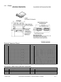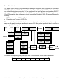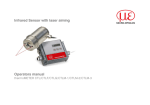
1
USER MANUAL UMAX020502
QUAD CONTROLLER
With CANopen®
USER MANUAL
P/N: AX020502
VERSION HISTORY
Version
1.00
1.01
Date
March 6, 2006
March 17, 2006
Author
Anna Murray
Anna Murray
1.02
March 21, 2006
Anna Murray
1.03
March 23, 2006
Anna Murray
1.04
1.05
March 24, 2006
July 20, 2010
Anna Murray
Anna Murray
1.06
2.00
Dec. 9, 2010
January 07, 2011
Amanda Wilkins
Anna Murray
Version 2.00
Modifications
Initial Draft
Changed PDO mappings from Optional to Yes
Fixed Digital Output Bitmap
Fixed a variety of typos
Fixed some more typos
Added LSS Reference
Added description for Object 1011h
Added hardware information
Added Analog Input sample rate
Added PWM Input filtering description
Fixed Analog Input Block diagram
Updated footer on cover page. Updated reference
to latest datasheet.
Added Appendix A – Technical Specifications
Added new object 5555h. Updated formating
Preliminary Documentation – May be Subject to Change
ii
TABLE OF CONTENTS
1. GENERAL …………………………………………………………………………………………………..………………. 5
1.1.
Axiomatic Quad Controller……………………………………………………………………………………….. 5
1.2.
Pinout……………………………………………………………………………………………………………….. 6
1.3.
References…………………………………………………………………………………………………………. 7
2. USING QUAD THROUGH CANOPEN……………………………………………………………………….………….. 8
2.1.
Node ID and Baudrate……………………………………………………………………………………………. 8
2.2.
Digital Inputs…………………………………..………………………………………………………..………….. 8
2.3.
Analog Inputs…………………………………..……………………………………………………….…………. 9
2.4.
Pulse Inputs…………………………………..……………………………………….…………………………… 10
2.5.
Digital Outputs…………………………………..…………………………………………………………………. 11
2.6.
Proportional Outputs…………………………………..……………………………………………….…………. 12
3. OBJECT DICTIONARY………………………………………………………………………………………...………….. 14
3.1.
COMMUNICATION OBJECTS………………………………………………………………………..…………. 14
3.1.1. PDO Parameters……………………………………………………………………………………………… 15
3.1.2. Object 1000h: Device Type………………………………………………………………………..………… 17
3.1.3. Object 1001h: Error Register……………………………………………………………………...………… 17
3.1.4. Object 1003h: Pre-Defined Error Field…………………………………………………………...………… 18
3.1.5. Object 1010h: Store Parameters………………………………………………………………….………… 19
3.1.6. Object 1011h: Restore Default Parameters……………………………………………………………….. 20
3.1.7. Object 1016h: Consumer Heartbeat Time……………………………………………………….………… 21
3.1.8. Object 1018h: Identity Object……………………………………………………………………..………… 22
3.1.9. Object 1029h: Error Behaviour……………………………………………………………………………… 23
3.1.10. Object 5555h: Start in Operational……….………………………………………………………………… 24
3.2.
DIGITAL INPUT FUNCTION BLOCK (DS-404)…………………………………………………….. ………… 25
3.2.1. Object 2000h: DI Level 8 Input Lines…………………………………………………………….………… 25
3.2.2. Object 2001h: DI Low Threshold………………………………………………………………….………… 26
3.2.3. Object 2002h: DI High Threshold…………………………………………………………………………… 27
3.2.4. Object 6000h: DI Read State 8 Input Lines……………………………………………………...………… 28
3.2.5. Object 6002h: DI Polarity 8 Input Lines…………………………………………………………..………... 28
3.3.
ANALOG INPUT FUNCTION BLOCK (DS-404)……………………………………………………. ………… 29
3.3.1. Object 2010h: AI Error Minimum………………………………………………………………….………… 29
3.3.2. Object 2020h: AI Minimum………………………………………………………………………...………… 30
3.3.3. Object 2030h: AI Breakpoint Minimum…………………………………………………………...………... 31
3.3.4. Object 2040h: AI Deadband Minimum…………………………………………………………...………… 31
3.3.5. Object 2050h: AI Deadband Maximum…………………………………………………………..………… 32
3.3.6. Object 2060h: AI Breakpoint Maximum…………………………………………………………..………... 33
3.3.7. Object 2070h: AI Maximum………………………………………………………………………..………… 33
3.3.8. Object 2080h: AI Error Maximum…………………………………………………………………………… 34
3.3.9. Object 2090h: AI Frequency Measuring Window……………………………………………….………… 35
3.3.10. Object 20A0h: AI Enable Error Checking 8 Input Lines………………………………………..………… 35
3.3.11. Object 20B0h: AI Error Response Delay…………………………………………………….…..………… 36
3.3.12. Object 7100h: AI Input Field Value…………………………………………………….…………………… 37
3.3.13. Object 6110h: AI Sensor Type…………………………………………………….……………………….. 38
3.3.14. Object 6112h: AI Operating Mode…………………………………………………….………….………… 39
3.3.15. Object 7120h: AI Input Scaling 1 FV…………………………………………………….……….………… 40
3.3.16. Object 7121h: AI Input Scaling 1 PV…………………………………………………….……….………… 40
Version 2.00
Preliminary Documentation – May be Subject to Change
iii
3.3.17. Object 7122h: AI Input Scaling 2 FV…………………………………………………….……….………… 41
3.3.18. Object 7123h: AI Input Scaling 2 PV…………………………………………………….……….………… 41
3.3.19. Object 7124h: AI Input Offset…………………………………………………….……………….………… 42
3.3.20. Object 6125h: AI Autozero…………………………………………………….…………………..………… 42
3.3.21. Object 7130h: AI Input Process Value…………………………………………………….……..………… 43
3.3.22. Object 6132h: AI Decimal Digits PV…………………………………………………….………..………… 43
3.3.23. Object 61A0h: AI Filter Type…………………………………………………….………………...……….. 44
3.3.24. Object 61A1h: AI Filter Constant…………………………………………………….……………………… 45
3.4.
DIGITAL OUTPUT FUNCTION BLOCK (DS-404)………………………………………………….. ………... 46
3.4.1. Object 3001h: DO Control Input…………………………………………………….…………….………… 46
3.4.2. Object 3002h: DO Response 8 Output Lines……………………………………….………………..…… 47
3.4.3. Object 300Bh: DO Error Response Delay…………………………………………………….…………… 48
3.4.4. Object 300Ch: DO Read State 8 Output Lines………………………………………………….………… 48
3.4.5. Object 6200h: DO Write State 8 Output Lines…………………………………………………..………… 49
3.4.6. Object 6202h: DO Polarity 8 Output Lines……………………………………………………….………... 50
3.4.7. Object 6206h: DO Fault Mode 8 Output Lines…………………………………………………..………… 50
3.4.8. Object 6207h: DO Fault State 8 Output Lines…………………………………………………..………… 51
3.5.
ANALOG OUTPUT FUNCTION BLOCK (DS-404)…………………………………………………. ………... 52
3.5.1. Object 3010h: AO Control Input…………………………………………………………………..………… 52
3.5.2. Object 3020h: AO Response……………………………………………………………………...………… 53
3.5.3. Object 3030h: AO Minimum Current……………………………………………………………..………… 54
3.5.4. Object 3040h: AO Breakpoint Current……………………………………………………………………… 55
3.5.5. Object 3050h: AO Maximum Current…………………………………………………………….………… 55
3.5.6. Object 3060h: AO Dither Frequency……………………………………………………………..………… 56
3.5.7. Object 3070h: AO Dither Amplitude………………………………………………………………………… 56
3.5.8. Object 3080h: AO Ramp Up………………………………………………………………………………… 57
3.5.9. Object 3090h: AO Ramp Down…………………………………………………………………...………… 57
3.5.10. Object 30A0h: AO Ramp Control…………………………………………………………………....……… 58
3.5.11. Object 30B0h: AO Error Response Delay……………………………………………………….………… 58
3.5.12. Object 30C0h: AO Measured Current……………………………………………………………………… 59
3.5.13. Object 7300h: AO Output Process Value………………………………………………………..………… 60
3.5.14. Object 6302h: AO Decimal Digits PV…………………………………………………………….………… 60
3.5.15. Object 6310h: AO Output Type…………………………………………………………………...………… 61
3.5.16. Object 7320h: AO Output Scaling 1 PV………………………………………………………….………… 62
3.5.17. Object 7321h: AO Output Scaling 1 FV………………………………………………………….………… 62
3.5.18. Object 7322h: AO Output Scaling 2 PV………………………………………………………….………… 63
3.5.19. Object 7323h: AO Output Scaling 2 FV………………………………………………………….………… 63
3.5.20. Object 7330h: AO Output Field Value……………………………………………………………………… 64
3.5.21. Object 6340h: AO Fault Mode…………………………………………………………………….………… 64
3.5.22. Object 7341h: AO Fault FV………………………………………………………………………..………… 65
3.5.23. Object 7F50h: Received PV 16…………………………………………………………..………...………. 65
3.5.24. Object 6F52h: Received PV Status………………………………………………………….……………... 66
4. ERROR HANDLING…………………………………………………………………………………………….………….. 67
4.1.
Emergency Frame Codes (EMCY)…………………………………………………………………… ……….. 67
4.2.
Quad Fault Mode Behaviour……………………………………………………………………………………... 68
APPENDIX A – TECHNICAL SPECIFICATIONS…………………………………………………………………………… A
Version 2.00
Preliminary Documentation – May be Subject to Change
iv
1. GENERAL
1.1.
Axiomatic Quad Controller
The Axiomatic Quad Controller is a CANopen compliant [DS-301] I/O module with a configurable
selection of I/O types. The Quad object dictionary is compatible with the CiA DS-404 device profile.
(Device profile for measurement devices and closed-loop controllers.) In addition to the standard
objects for this device profile, the Quad also includes a number of manufacturer specific objects to
extend the functionality beyond that of the basic profile.
The module includes the following I/O:
• Four (4) software configurable analog inputs that can be configured as voltage [0-5V] or [010V], current [0-20mA] or [4-20mA], or ON/OFF input with programmable threshold levels, or
active high/low digital input.
Named AIN1 to AIN4
• Two (2) software configurable pulse inputs that can be configured as PWM [0-100% duty
cycle], or frequency [0-10,000Hz] or ON/OFF input with programmable threshold levels, or
active high/low digital input.
Named FIN1 to FIN2
• Four (4) proportional outputs that can be software configured for either closed-loop current
control or digital outputs. Maximum is 2A/channel, sourcing.
Named POUT1 to POUT4
• One (1) ON/OFF output for up to 5A load, sourcing.
Named DOUT
Note: Total current consumption of all the outputs combined must not exceed 6A.
A convenient feature of the CANopen Quad is the ability to map any input on the board as the
control signal for any output. This feature is described in greater detail in section 2.
Refer to datasheet TDAX020502 for full electrical specifications of the inputs and outputs.
Version 2.00
Preliminary Documentation – May be Subject to Change
5-71
1.2.
Pinout
Deutsch Connector Pinout
Grey Connector
Black Connector
Pin # Function
Pin #
Function
1
Power +
1
CANH
12
Power 2
CANL
2
Proportional Solenoid 1 + (POUT1)
3
Analog Input 1/Digital Input 1 (AIN1/DIN1)
11
Proportional Solenoid 1 4
Analog Input 2/Digital Input 2 (AIN2/DIN2)
3
Proportional Solenoid 2 + (POUT2)
5
Analog Input 3/Digital Input 3 (AIN3/DIN3)
10
Proportional Solenoid 2 6
Analog Input 4/Digital Input 4 (AIN4/DIN4)
4
Proportional Solenoid 3 + (POUT3)
7
RS-232 Transmit
9
Proportional Solenoid 3 8
RS-232 Receive
5
Proportional Solenoid 4 + (POUT4)
9
Analog GND (could be used as RS-232 GND)
8
Proportional Solenoid 4 10
Analog +5V Reference, 10mA
6
Digital Solenoid +
(DOUT)
11
Pulse Input 1/Digital Input 5 (FIN1/DIN5)
7
Digital Solenoid 12
Pulse Input 2/Digital Input 6 (FIN2/DIN6)
Note: An analog input can be configured for 0-5V, 0-10V, 0-20mA or 4-20mA input types
Connector to DB-9 Pinout (RS-232 Connection)
Black Deutsch Connector
Pin #
Controller Function
7
RS-232 Transmit
8
RS-232 Receive
9
GND
Version 2.00
DB-9 Female
Pin #
PC Function
2
RS-232 Receive
3
RS-232 Transmit
5
GND
Preliminary Documentation – May be Subject to Change
6-71
1.3.
References
[DS-301]
CiA DS-301 V4.02 – CANopen Application Layer and Communication
Profile. CAN in Automation 2002
[DS-404]
CiA DS-404 V1.2 – Device Profile for Measurement Devices and
Closed-Loop Controllers. CAN in Automation 2002
[DS-305]
CiA DS-305 V2.0 – Layer Setting Service (LSS) and Protocols. CAN in
Automation 2006
LSS Protocol, User’s Manual V1.2. Axiomatic Technologies 2004
TDAX020502
Version 2.00
Technical Datasheet, CANopen Quad. Axiomatic Technologies 2010
Preliminary Documentation – May be Subject to Change
7-71
2. USING QUAD THROUGH CANOPEN
2.1.
Node ID and Baudrate
The Quad supports the Layer Setting Service (LSS) protocols to configure the node-id and
baudrate. Refer to the document “LSS Protocol” for more details.
2.2.
Digital Inputs
The digital input function block handles the reading of any input pin configured as either a digital
input, or an ON/OFF input with programmable threshold levels. Note, however, the analog input
operating mode is set through the object 6112h, in the analog input function block. For inputs that
are NOT configured as digital or ON/OFF, the objects associated with the digital input block are
ignored.
A manufacturer specific object 2000h has been introduced for setting the digital input active level.
On the Quad, the digital input pins have a software-configurable hardware polarity, so the inputs
can act as either active high or active low inputs. The application object 6002h also allows the
input polarity to be changed in software. The combination of the hardware level and software
polarity allows the digital inputs to work with any wiring scheme, and they are capable of acting as
either as an enable (on when switch is closed) or disable (off when switch is closed) signal.
Digital Input
Operation
Input Pin
H/W Level
Select
6112h
2000h
S/W Polarity
Select
6000h
6002h
If configured as an ON/OFF input with programmable threshold levels, the manufacturer specific
objects 2001h and 2002h are used to determine the ON/OFF state. If the input measured is less
than or equal to object 2001h [low threshold] the input is off. If greater than or equal to object
2002h [high threshold] (when 2001h not equal 2002h) the input is on. If the measured value is
between the two thresholds, the input does not change state from the last reading. In this case, the
object 6002h is ignored.
On/Off Input
Operation
Input Pin
6112h
Compare
Low Thres.
2001h
Compare
High Thres.
6000h
2002h
For objects corresponding to 8 digital input lines on the controller, the bit order is as shown.
7
0
XXX
Version 2.00
XXX
DIN 6
DIN 5
DIN 4
DIN 3
DIN 2
Preliminary Documentation – May be Subject to Change
DIN 1
8-71
2.3.
Analog Inputs
The analog input function block handles the reading of any input configured as an analog input by
the object 6112h. The type of input is determined by object 6110h, and can be set to one of the
following four modes. Note, if the operation of the input has been configured as ON/OFF with
programmable threshold levels, object 6110h also applies. Analog inputs are sampled every 10ms.
• Voltage input, range 0-5V
• Voltage input, range 0-10V
• Current input, range 0-20mA
• Current input, range 4-20mA
The conversion from input field value to process value is generally described as a linear
transformation. The two pairs of field values and their corresponding process values define
calibration points 1 and 2. (Input Scaling 1 FV/ Input Scaling 1 PV and Input Scaling 2 FV/ Input
Scaling 2 PV) See DS-404 for more information.
If error checking on an input is enabled by object 20A0h, then the controller
measured field value to the values in objects 2010h [Error Minimum] and 2080h
If less than 2010h, or greater than 2080h, the controller will flag an error after
object 20B0h has passed. (See section 4 for more details on emergency
controller’s response to errors.)
Input
Pin
AtoD
Conv.
Operation
6112h
Controller
Meas.
Calc.
Filter AIN
61A0h
Input Type
6110h
Constant
61A1h
Field Value
7100h
Scaling
Output
Control
Minimum
2020h
will compare the
[Error Maximum].
the delay time in
objects, and the
Dec. Digits
6132h
Scale 1 FV
7120h
Scale 1 PV
7121h
Scale 2 FV
7122h
Scale 2 PV
7123h
Offset
7124h
Autozero
6125h
Proc. Val
7130h
Err Min
2010h
CAN Bus
Through To
Err Max
2080h
Maximum
2070h
Err Active
20A0h
Error
Checking
Error
React
Err Delay
20B0h
Controller
Since the analog inputs can be used to control any off the outputs on the quad, independent of
CANopen, there are a number of manufacturer parameters that will determine how the output
responds to a change at the inputs. If an output control signal has been set to one of the analog
inputs, it uses the input field value as the control input. See sections 2.4 and 2.5 for more details.
For objects corresponding to 8 analog input lines on the controller, the bit order is as shown.
7
0
XXX
Version 2.00
XXX
FIN 2
FIN 1
AIN 4
AIN 3
AIN 2
Preliminary Documentation – May be Subject to Change
AIN 1
9-71
2.4.
Pulse Inputs
The analog input function block handles the reading of any pulse input configured as normal or
ON/OFF by the object 6112h. The type of input is determined by object 6110h, and can be set to
one of the following two modes. Note, if the operation of the input has been configured as ON/OFF
with programmable threshold levels, object 6110h also applies. PWM inputs are sampled every
10ms. The sampling time of frequency inputs is controlled by object 2090h [Frequency Measuring
Window].
• PWM Input, range 0-100% Duty Cycle
• Frequency Input, range 0-10,000 Hz
The conversion from input field value to process value, and error checking is handled exactly the
same as with analog inputs, as described in Section 2.2. Either pulse input could also be used as a
control signal for the outputs on the quad.
Input
Pin
Count/
Timer
Operation
6112h
Controller
Meas.
Calc.
Filter PWM
61A0h
Input Type
6110h
Constant
61A1h
Field Value
7100h
Scaling
Window
2090h
Output
Control
Minimum
2020h
Err Min
2010h
Through To
Err Max
2080h
Dec. Digits
6132h
Scale 1 FV
7120h
Scale 1 PV
7121h
Scale 2 FV
7122h
Scale 2 PV
7123h
Offset
7124h
Autozero
6125h
Proc. Val
7130h
CAN Bus
Error
Checking
Error
React
Err Delay
20B0h
Controller
Maximum
2070h
Err Active
20A0h
For objects corresponding to 8 pulse input lines on the controller, the bit order is as shown.
7
0
XXX
Version 2.00
XXX
FIN 2
FIN 1
AIN 4
AIN 3
AIN 2
Preliminary Documentation – May be Subject to Change
AIN 1
10-71
2.5.
Digital Outputs
The digital output function block handles the control of the digital output on the quad, as well as
any off the proportional outputs that have been configured as a digital output. Note that for
proportional outputs, the digital output operating mode is set through the object 6310h, in the
analog output function block.
All digital outputs can be controlled by either a digital or ON/OFF input on the controller, or by
writes to object 6200h (DO Write States), but not both methods at once. Manufacturer object
3001h dictates the control signal for the output. Since an output can be controlled independent of
object 6200h, a manufacturer object 300Ch has been introduced to show the read states of the
digital outputs as a means of indicating states to the bus at any time.
Object 6202h sets the polarity of the output, determining if the output will be on (normal) or off
(inverted) when control input is on. Manufacturer object 3002h determines if the output will have a
standard on/off response to the control input, or if it will have a latched response. In latched mode,
object 6202h is ignored, and when the input comes on, the output will come on, and stay on. When
the input comes on again (after having been off), the output will turn off, and stay off until the
output comes on again, repeating the cycle.
If an error is detected on the output, the controller will flag an error after the delay time in object
300Bh has passed. Objects 6206h (DO fault mode) and objects 6207h (DO fault state) apply to
any output configured as a digital output. Refer to Section 4 for a detailed description of a digital
output’s response to an error.
Write State
6200h
Latched
Output Logic
Control
3001h
Response
3002h
Output Pin
Control
Digital/
ON/OFF Input
ON/OFF
Output Logic
CAN Bus
Controller
Error React
Polarity
6202h
Error Delay
300Bh
Error
Checking
Read State
300Ch
Output Pin
Feedback
Load
For objects corresponding to 8 digital output lines on the controller, the bit order is as shown.
7
0
XXX
Version 2.00
XXX
XXX
DOUT
POUT4
POUT3
POUT2
Preliminary Documentation – May be Subject to Change
POUT1
11-71
2.6.
Proportional Outputs
The analog output function block handles the control of the proportional outputs on the quad that
have been configured for current output by object 6310h.
All proportional outputs can be controlled by either an analog or pulse input on the controller, or by
writes to object 7330h (AO Field Value)/object 7F50h (Received PV), but not both methods at
once. Manufacturer object 3010h dictates the control signal for the output. Since an output can be
controlled independent of object 7330h, a manufacturer object 30C0h has been introduced as a
means of indicating the measured feedback current of the outputs to the bus at any time.
The object 7F50h can be mapped to a PDO to send a process value to the controller. In order for
the controller to accept the received PV, the status of object 6F52h must be validated. The
conversion from received process value to field value is generally described as a linear
transformation. The two pairs of process values and their corresponding field values define
calibration points 1 and 2. (Input Scaling 1 PV/ Input Scaling 1 FV and Input Scaling 2 PV/ Input
Scaling 2 FV) See DS-404 for more information.
Some manufacturer objects have been introduced for the case where a proportional output is
being controlled by an input on the Quad. These objects are 3020h (response), 3030h (minimum
current), 3040h (breakpoint current), and 3050h (maximum current). The response of the output
will be as shown in one of the graphs below, depending on the setting of object 3020h. If the
output’s control signal is a CANopen message (FV or PV), then these objects are ignored.
Manufacturer dither objects 3060h (frequency) and 3070h (amplitude) apply regardless of which
control signal is selected. Ramp objects 3080h (up) and 3090h (down) can apply or not depending
on the setting of object 30A0h (ramp control).
If an error is detected on the output, the controller will flag an error after the delay time in object
30B0h has passed. Objects 6340h (AO fault mode) and objects 7341h (AO fault FV) apply to any
output configured as a current output. Refer to Section 4 for a detailed description of a proportional
output’s response to an error.
Received PV
7F50h
Scale 1 PV
7320h
Scale 1 FV
7321h
Dec. Digit
6302h
Scale 2 PV
7322h
Scale 2 FV
7323h
Process Val.
7300h
Scaling
Field Value
7330h
Control
3010h
Response
3020h
Analog
Output Logic
Analog/Pulse
Input
Currents
3020h/3030h
/3040h
Load
Output Pin
Command
PV Status
6F52h
Field Value
7330h
Version 2.00
Dither
3060h/3070h
Ramps
3080h/3090h
/30A0h
Preliminary Documentation – May be Subject to Change
Error
Checking
Output Pin
Feedback
Error Delay
30B0h
Meas. Curr
30C0h
Error React
CAN Bus
Controller
12-71
SINGLE PROFILE
I [mA]
Single Slope
Dual Slope
Either, with Error Checking
Either, no Error Checking
ERROR MODE
ERROR MODE
AO Maximum
3050h
AO Breakpoint
3040h
AO Minimum
3030h
INPUT
0
AI Minimum
2020h
AI Error Minimum
2010h
AI Breakpoint Minimum
2030h
AI Maximum
2070h
AI Error Maximum
2080h
DUAL PROFILE A
I [mA]
AO Maximum
3050h
ERROR MODE
Single Slope
Dual Slope
Either, with Error Checking
Either, no Error Checking
AO Breakpoint
3040h
AO Minimum
3030h
INPUT
AI Deadband Maximum
2050h
I [mA]
AI Breakpoint Maximum
2060h
AI Maximum
2070h
AI Error Maximum
2080h
DUAL PROFILE B
ERROR MODE
AO Maximum
3050h
Single Slope
Dual Slope
Either, with Error Checking
Either, no Error Checking
AO Breakpoint
3040h
AO Minimum
3030h
INPUT
0
AI Minimum
2020h
AI Error Minimum
2010h
Version 2.00
AI Breakpoint Minimum
2030h
AI Deadband Minimum
2040h
Preliminary Documentation – May be Subject to Change
13-71
3. OBJECT DICTIONARY
The CANopen object dictionary of the Quad Controller is based on CiA device profile DS-404 V1.2.
(Device profile for measurement devices and closed-loop controllers.) The object dictionary also
includes some manufacturer-specific objects for extended functionality.
3.1.
COMMUNICATION OBJECTS
The communication objects supported by the Quad are listed in the following table. A more
detailed description of some of the objects is given in the following subchapters. Only those objects
that have device-profile specific information are described. For more information on the other
objects, refer to the generic CANopen protocol specification DS-301.
Index
(hex)
Object
Object Type
Data Type
Access
PDO
Mapping
1000
1001
1002
1003
100C
100D
1010
1011
1016
1017
1018
1020
1029
1400
1401
1402
1403
1600
1601
1602
1603
1800
1801
1802
1803
1A00
1A01
1A02
1A03
Device Type
Error Register
Manufacturer Status Register
Pre-Defined Error Field
Guard Time
Life Time Factor
Store Parameters
Restore Default Parameters
Consumer Heartbeat Time
Producer Heartbeat Time
Identity Object
Verify Configuration
Error Behaviour
RPDO1 Communication Parameter
RPDO2 Communication Parameter
RPDO3 Communication Parameter
RPDO4 Communication Parameter
RPDO1 Mapping Parameter
RPDO2 Mapping Parameter
RPDO3 Mapping Parameter
RPDO4 Mapping Parameter
TPDO1 Communication Parameter
TPDO2 Communication Parameter
TPDO3 Communication Parameter
TPDO4 Communication Parameter
TPDO1 Mapping Parameter
TPDO2 Mapping Parameter
TPDO3 Mapping Parameter
TPDO4 Mapping Parameter
VAR
VAR
VAR
ARRAY
VAR
VAR
ARRAY
ARRAY
ARRAY
VAR
RECORD
ARRAY
ARRAY
RECORD
RECORD
RECORD
RECORD
RECORD
RECORD
RECORD
RECORD
RECORD
RECORD
RECORD
RECORD
RECORD
RECORD
RECORD
RECORD
UNSIGNED32
UNSIGNED8
UNSIGNED32
UNSIGNED32
UNSIGNED16
UNSIGNED8
UNSIGNED32
UNSIGNED32
UNSIGNED32
UNSIGNED16
RO
RO
RO
RO
RW
RW
RW
RW
RW
RW
RO
RW
RW
RW
RW
RW
RW
RW
RW
RW
RW
RW
RW
RW
RW
RW
RW
RW
RW
No
No
No
No
No
No
No
No
No
No
No
No
No
No
No
No
No
No
No
No
No
No
No
No
No
No
No
No
No
Version 2.00
UNSIGNED32
UNSIGNED8
Preliminary Documentation – May be Subject to Change
14-71
3.1.1. PDO Parameters
All RPDOs and TPDOs in the Quad use the same default communication parameters,
respectively. The PDO IDs are set according to the pre-defined connection set described in
[DS-301]. All receive PDOs are set to transmission type 255, and all transmit PDOs to
transmission type 254, with the event timer (subindex 5) set to 100 (100ms).
All PDOs are dynamically mappable, and the user can therefore change the mapping of the
PDOs. The granularity is 8-bits, so the objects can be mapped with byte offsets. The
mapping parameter records include 4 subindexes for the PDO mapping. The default PDO
mappings are listed in the following tables.
RPDO1: default ID 0x200 + node ID
Subindex Value
0
4
1
0x73300110
2
0x73300210
3
0x73300310
4
0x73300410
Object
Number of mapped application objects in PDO
AO Output Field Value for POUT1
AO Output Field Value for POUT2
AO Output Field Value for POUT3
AO Output Field Value for POUT4
RPDO2: default ID 0x300 + node ID
Subindex Value
Object
0
1
Number of mapped application objects in PDO
1
0x62000108
DO Write State 8 Output Lines
2
0
3
0
4
0
RPDO3: default ID 0x400 + node ID
Subindex Value
Object
0
0
Number of mapped application objects in PDO
1
0
2
0
3
0
4
0
RPDO4: default ID 0x500 + node ID
Subindex Value
Object
0
0
Number of mapped application objects in PDO
1
0
2
0
3
0
4
0
Version 2.00
Preliminary Documentation – May be Subject to Change
15-71
TPDO1: default ID 0x180 + node ID
Subindex Value
0
4
1
0x71000110
2
0x71000210
3
0x71000310
4
0x71000410
TPDO2: default ID 0x280 + node ID
Subindex Value
0
2
1
0x71000510
2
0x71000610
3
0
4
0
TPDO3: default ID 0x380 + node ID
Subindex Value
0
2
1
0x60000108
2
0x300C0108
3
0
4
0
TPDO4: default ID 0x480 + node ID
Subindex Value
0
4
1
0x30C00110
2
0x30C00210
3
0x30C00310
4
0x30C00410
Version 2.00
Object
Number of mapped application objects in PDO
AI Input Field Value for AIN1
AI Input Field Value for AIN2
AI Input Field Value for AIN3
AI Input Field Value for AIN4
Object
Number of mapped application objects in PDO
AI Input Field Value for FIN1
AI Input Field Value for FIN2
Object
Number of mapped application objects in PDO
DI Read State 8 Input Lines
DO Read State 8 Output Lines
Object
Number of mapped application objects in PDO
AO Measured Current for POUT1
AO Measured Current for POUT2
AO Measured Current for POUT3
AO Measured Current for POUT4
Preliminary Documentation – May be Subject to Change
16-71
3.1.2. Object 1000h: Device Type
This object contains information about the device type as per device profile DS-404. The
value stored in this object is 0x000F0194, indicating that the Quad includes the following
function blocks defined in the device profile.
• Digital Input
(DI)
• Analog Input
(AI)
• Digital Output (DO)
• Analog Output (AO)
Object Description
Index
Name
Object Type
Data Type
1000h
Device Type
VAR
UNSIGNED32
Entry Description
Access
PDO Mapping
Value Range
Default Value
RO
No
0x000F0194
0x000F0194
3.1.3. Object 1001h: Error Register
This object is an error register for the device. Any time there is an error detected by the
Quad, the Generic Error Bit (bit 0) is set. Only if there are no errors in the module will this bit
be cleared. No other bits in this register are used by the Quad.
Object Description
Index
Name
Object Type
Data Type
1001h
Error Register
VAR
UNSIGNED8
Entry Description
Access
PDO Mapping
Value Range
Default Value
Version 2.00
RO
No
00h or 01h
0
Preliminary Documentation – May be Subject to Change
17-71
3.1.4. Object 1003h: Pre-Defined Error Field
The object 1003h provides an error history by listing the errors in the order that they have
occurred. An error is added to the top of the list when it occurs, and is immediately removed
when the error condition has been cleared. The latest error is always at subindex 1, with
subindex 0 containing the number of errors currently in the list. When the device is in an
error-free state, the value of subindex 0 is zero.
The error list may be cleared by writing a zero to subindex 0, which will clear all errors from
the list, regardless of whether or not they are still present. Clearing the list does NOT mean
that the module will return to the error-free behaviour state if at least one error is still active.
The Quad has a limitation of a maximum of 16 errors in the list. If the device registers more
errors, the list will be truncated, and the oldest entries will be lost.
The error codes stored in the list are 32-bit unsigned numbers, consisting of two 16-bit
fields. The lower 16-bit field is the EMCY error code, and the higher 16-bit field is a
manufacturer-specific code. The manufacturer-specific code is divided into two 8-bit fields,
with the higher byte indicating the error description, and the lower byte indicating the
channel number where the error occurred.
MSB
Error Description
LSB
Channel
EMCY Error Code
See Section 4 for a complete list of the error code fields.
Object Description
Index
Name
Object Type
Data Type
1003h
Pre-Defined Error Field
VAR
UNSIGNED32
Entry Description
Subindex
Description
Access
PDO Mapping
Value Range
Default Value
0h
Number of entries
RO
No
0 to 16
0
Subindex
Description
Access
PDO Mapping
Value Range
Default Value
1h to 10h
Standard error field
RO
No
UNSIGNED32
0
Version 2.00
Preliminary Documentation – May be Subject to Change
18-71
3.1.5. Object 1010h: Store Parameters
This object supports the saving of parameters in non-volatile memory. In order to avoid
storage of parameters by mistake, storage is only executed when a specific signature is
written to the appropriate subindex. The signature is “save”.
The signature is a 32-bit unsigned number, composed of the ASCII codes of the signature
characters, according to the following table:
MSB
e
65h
v
76h
a
61h
LSB
s
73h
On reception of the correct signature to an appropriate subindex, the Quad will store the
parameters in non-volatile memory, and then confirm the SDO transmission.
By read access, the object provides information about the Quad’s saving capabilities.
Object Description
Index
Name
Object Type
Data Type
1010h
Store Parameters
ARRAY
UNSIGNED32
Entry Description
Subindex
Description
Access
PDO Mapping
Value Range
Default Value
0h
Largest subindex supported
RO
No
4
4
Subindex
Description
Access
PDO Mapping
Value Range
1h
Save all parameters
RW
No
0x65766173 (write access)
(read access)
1h
1h (saves parameters on command)
Default Value
Subindex
Description
Access
PDO Mapping
Value Range
Default Value
Subindex
Description
Access
PDO Mapping
Value Range
Default Value
Version 2.00
2h
Save communication parameters
RW
No
0x65766173 (write access)
1h
(read access)
1h (saves parameters on command)
3h
Save application parameters
RW
No
0x65766173 (write access)
1h
(read access)
1h (saves parameters on command)
Preliminary Documentation – May be Subject to Change
19-71
Subindex
Description
Access
PDO Mapping
Value Range
Default Value
4h
Save manufacturer parameters
RW
No
0x65766173 (write access)
(read access)
1h
1h (saves parameters on command)
3.1.6. Object 1011h: Restore Default Parameters
This object supports the restoring of the default values for the object dictionary in nonvolatile memory. In order to avoid restoring of parameters by mistake, the device restores
the defaults only when a specific signature is written to the appropriate subindex. The
signature is “load”.
The signature is a 32-bit unsigned number, composed of the ASCII codes of the signature
characters, according to the following table:
MSB
d
64h
a
61h
o
6Fh
LSB
l
6Ch
On reception of the correct signature to an appropriate subindex, the Quad will restore the
defaults in non-volatile memory, and then confirm the SDO transmission. The default values
are set valid after the device is reset or power-cycled.
By read access, the object provides information about the Quad’s default parameter
restoring capabilities.
Object Description
Index
Name
Object Type
Data Type
1011h
Restore Default Parameters
ARRAY
UNSIGNED32
Entry Description
Subindex
Description
Access
PDO Mapping
Value Range
Default Value
0h
Largest subindex supported
RO
No
4
4
Subindex
Description
Access
PDO Mapping
Value Range
1h
Restore all default parameters
RW
No
0x64616F6C (write access)
1h
(read access)
1h (restores defaults on command)
Default Value
Subindex
Description
Access
PDO Mapping
Version 2.00
2h
Restore default communication parameters
RW
No
Preliminary Documentation – May be Subject to Change
20-71
Value Range
0x64616F6C (write access)
1h
(read access)
1h (restores defaults on command)
Default Value
Subindex
Description
Access
PDO Mapping
Value Range
Default Value
Subindex
Description
Access
PDO Mapping
Value Range
Default Value
3h
Restore default application parameters
RW
No
0x64616F6C (write access)
1h
(read access)
1h (restores defaults on command)
4h
Restore default manufacturer parameters
RW
No
0x64616F6C (write access)
1h
(read access)
1h (restores defaults on command)
3.1.7. Object 1016h: Consumer Heartbeat Time
The Quad can be a consumer of heartbeat objects for up to four modules. This object
defines the expected heartbeat cycle time for those modules, and if set to zero, it is not
used. When non-zero, the time is a multiple of 1ms, and monitoring will start after the
reception of the first heartbeat from the module. If the Quad fails to receive a heartbeat from
a node in the expected timeframe, it will indicate a communication error, and respond as per
object 1029h.
Bits
Value
Encoded as
31-24
Reserved 00h
23-16
Node-ID
UNSIGNED8
15-0
Heartbeat time
UNSIGNED16
Object Description
Index
Name
Object Type
Data Type
1016h
Consumer heartbeat time
ARRAY
UNSIGNED32
Entry Description
Subindex
Description
Access
PDO Mapping
Value Range
Default Value
0h
Number of entries
RO
No
4
4
Subindex
Description
Access
PDO Mapping
Value Range
Default Value
1h to 4h
Consumer heartbeat time
RW
No
UNSIGNED32
0
Version 2.00
Preliminary Documentation – May be Subject to Change
21-71
3.1.8. Object 1018h: Identity Object
The identity object indicates the data of the Quad, including vendor id, device id, software
and hardware version numbers, and the serial number.
In the Revision Number entry at subindex 3, the format of the data is as shown below
MSB
Major revision number (object dictionary)
Hardware Revision
LSB
Software Version
Object Description
Index
Name
Object Type
Data Type
1018h
Identity
RECORD
Identity Record
Entry Description
Subindex
Description
Access
PDO Mapping
Value Range
Default Value
0h
Number of entries
RO
No
4
4
Subindex
Description
Access
PDO Mapping
Value Range
Default Value
1h
Vendor ID
RO
No
0x00000055
0x00000055 (Axiomatic)
Subindex
Description
Access
PDO Mapping
Value Range
Default Value
2h
Product Code
RO
No
0xAA020502
0xAA020502
Subindex
Description
Access
PDO Mapping
Value Range
Default Value
3h
Revision Number
RO
No
UNSIGNED32
No
Subindex
Description
Access
PDO Mapping
Value Range
Default Value
4h
Serial Number
RO
No
UNSIGNED32
No
Version 2.00
Preliminary Documentation – May be Subject to Change
22-71
3.1.9. Object 1029h: Error Behaviour
This object controls the state that the Quad will be set into in case of an error of the type
associated with the subindex. The behaviour of the Quad in each state is described in detail
in section 4.
Object Description
Index
Name
Object Type
Data Type
1029h
Error Behaviour
ARRAY
UNSIGNED8
Entry Description
Subindex
Description
Access
PDO Mapping
Value Range
Default Value
0h
Number of entries
RO
No
5
5
Subindex
Description
Access
PDO Mapping
Value Range
1h
Communication Error
RW
No
0 = Pre-Operational
1 = No State Change
2 = Stopped
0 (Pre-Operational)
Default Value
Subindex
Description
Access
PDO Mapping
Value Range
Default Value
Subindex
Description
Access
PDO Mapping
Value Range
Default Value
Version 2.00
2h
Digital Input Error
RW
No
0 = Pre-Operational
1 = No State Change
2 = Stopped
1 (no state change)
3h
Analog Input Error
RW
No
0 = Pre-Operational
1 = No State Change
2 = Stopped
1 (no state change)
Preliminary Documentation – May be Subject to Change
23-71
Subindex
Description
Access
PDO Mapping
Value Range
Default Value
Subindex
Description
Access
PDO Mapping
Value Range
Default Value
4h
Digital Output Error
RW
No
0 = Pre-Operational
1 = No State Change
2 = Stopped
1 (no state change)
5h
Analog Output Error
RW
No
0 = Pre-Operational
1 = No State Change
2 = Stopped
1 (no state change)
3.1.10.
Object 5555h: Start in Operational
This manufacturer specific object allows the unit to start in Operational mode without
requiring the presence of a CANopen ® Master on the network. It is intended to be used
only when running the controller as a stand-alone module. This should always be set
FALSE whenever it is connected to a standard master/slave network.
Object Description
Index
5555h
Name
Start in Operational Mode
Object Type
VARIABLE
Data Type
BOOLEAN
Entry Description
Sub-Index
0h
Access
RW
PDO Mapping
No
Value Range
0 (FALSE) or 1 (TRUE)
Default Value
0 [FALSE]
Version 2.00
Preliminary Documentation – May be Subject to Change
24-71
3.2.
DIGITAL INPUT FUNCTION BLOCK (DS-404)
The application and manufacturer objects supported by the Quad for the digital input block are
listed in the following table.
Index Object
Object Type
Data Type
Access PDO
(hex)
Mapping
2000
2001
2002
6000
6002
DI Level 8 Input Lines
DI Low Threshold
DI High Threshold
DI Read State 8 Input Lines
DI Polarity 8 Input Lines
ARRAY
ARRAY
ARRAY
ARRAY
ARRAY
UNSIGNED8
UNSIGNED16
UNSIGNED16
UNSIGNED8
UNSIGNED8
RW
RW
RW
RO
RW
No
No
No
Yes
No
3.2.1. Object 2000h: DI Level 8 Input Lines
This object sets the digital input active level for input pins configured as digital inputs. The
digital inputs have a software selectable pull-up/pull-down resistor, which is switched
according to the state of the bit in this object. In active high mode, the pull-down resistor is
enabled, so the input must be switched to a +V signal to turn on. In active low mode, the
pull-up resistor is enabled, so the input must be switched to a GND signal to turn on. In
either mode, the inputs do not require any external components to function properly.
Object Description
Index
Name
Object Type
Data Type
2000h
DI Level 8 Input Lines
ARRAY
UNSIGNED8
Entry Description
Subindex
Description
Access
PDO Mapping
Value Range
Default Value
0h
Number of entries
RO
No
1
1
Subindex
Description
Access
PDO Mapping
Value Range
1h
Active Level of DIN1 to DIN6
RW
No
Bit Value 0 = Active Low Input
Bit Value 1 = Active High Input
3Fh (all active high)
Default Value
Version 2.00
Preliminary Documentation – May be Subject to Change
25-71
3.2.2. Object 2001h: DI Low Threshold
This object sets the off threshold for analog inputs configured as ON/OFF inputs. If the input
is less than or equal to this value, then the input state in object 6000h is set to OFF. This
input must be in the same units as object 7100h, the field value for that analog input.
Object Description
Index
Name
Object Type
Data Type
2001h
DI Low Threshold
ARRAY
UNSIGNED16
Entry Description
Subindex
Description
Access
PDO Mapping
Value Range
Default Value
0h
Number of entries
RO
No
6
6
Subindex
Description
Access
PDO Mapping
Value Range
Default Value
1h to 4h
Low Threshold, AIN1 to AIN4
RW
No
0 to 2002h at subindex
1500 [mV]
Subindex
Description
Access
PDO Mapping
Value Range
Default Value
5h to 6h
Low Threshold, FIN1 to FIN2
RW
No
0 to 2002h at subindex
2500 [25.00%]
Version 2.00
Preliminary Documentation – May be Subject to Change
26-71
3.2.3. Object 2002h: DI High Threshold
This object sets the on threshold for analog inputs configured as ON/OFF inputs. If the input
is greater than or equal to this value, then the input state in object 6000h is set to ON. This
input must be in the same units as object 7100h, the field value for that analog input.
Object Description
Index
Name
Object Type
Data Type
2002h
DI High Threshold
ARRAY
UNSIGNED16
Entry Description
Subindex
Description
Access
PDO Mapping
Value Range
Default Value
0h
Number of entries
RO
No
6
6
Subindex
Description
Access
PDO Mapping
Value Range
1h to 4h
High Threshold, AIN1 to AIN4
RW
No
Default Value
3500 [mV]
Subindex
Description
Access
PDO Mapping
Value Range
5h to 6h
High Threshold, FIN1 to FIN2
RW
No
Default Value
7500 [75.00%]
Version 2.00
2001h at subindex to 5000, for 0-5V
2001h at subindex to 10000, for 0-10V
2001h at subindex to 20000, for 0-20mA
2001h at subindex to 10000,
for both 0-100.00% and 0-10000Hz
Preliminary Documentation – May be Subject to Change
27-71
3.2.4. Object 6000h: DI Read State 8 Input Lines
This object is used for reading data from digital input lines in 8-bit blocks. For inputs that are
not configured as either digital or ON/OFF with programmable threshold by object 6112h,
the corresponding bit in the read byte is always set to 0.
Object Description
Index
Name
Object Type
Data Type
6000h
DI Read State 8 Input Lines
ARRAY
UNSIGNED8
Entry Description
Subindex
Description
Access
PDO Mapping
Value Range
Default Value
0h
Number of entries
RO
No
1
1
Subindex
Description
Access
PDO Mapping
Value Range
1h
Read State of DIN1 to DIN6
RO
Yes (default TPDO3, subindex 1)
Bit Value 0 = Input Off
Bit Value 1 = Input On
0
Default Value
3.2.5. Object 6002h: DI Polarity 8 Input Lines
This object is used for setting the polarity of digital input lines in 8-bit blocks. For inputs that
are not configured as digital inputs by object 6112h, the corresponding bit is ignored.
Object Description
Index
Name
Object Type
Data Type
6000h
DI Polarity 8 Input Lines
ARRAY
UNSIGNED8
Entry Description
Subindex
Description
Access
PDO Mapping
Value Range
Default Value
0h
Number of entries
RO
No
1
1
Subindex
Description
Access
PDO Mapping
Value Range
1h
Polarity of DIN1 to DIN6
RW
No
Bit Value 0 = normal polarity
Bit Value 1 = inverted polarity
00h (all normal polarity)
Default Value
Version 2.00
Preliminary Documentation – May be Subject to Change
28-71
3.3. ANALOG INPUT FUNCTION BLOCK (DS-404)
The application and manufacturer objects supported by the Quad for the analog input block are
listed in the following table.
Index Object
Object Type
Data Type
Access PDO
(hex)
Mapping
2010
2020
2030
2040
2050
2060
2070
2080
2090
20A0
20B0
7100
6110
6112
7120
7121
7122
7123
7124
6125
7130
6132
61A0
61A1
AI Error Minimum
AI Minimum
AI Breakpoint Minimum
AI Deadband Minimum
AI Deadband Maximum
AI Breakpoint Maximum
AI Maximum
AI Error Maximum
AI Frequency Measuring Window
AI Enable Error Checking 8 Lines
AI Error Response Delay
AI Input Field Value
AI Sensor Type
AI Operating Mode
AI Input Scaling 1 FV
AI Input Scaling 1 PV
AI Input Scaling 2 FV
AI Input Scaling 2 PV
AI Input Offset
AI Autozero
AI Input Process Value
AI Decimal Digits PV
AI Filter Type
AI Filter Constant
ARRAY
ARRAY
ARRAY
ARRAY
ARRAY
ARRAY
ARRAY
ARRAY
ARRAY
ARRAY
ARRAY
ARRAY
ARRAY
ARRAY
ARRAY
ARRAY
ARRAY
ARRAY
ARRAY
ARRAY
ARRAY
ARRAY
ARRAY
ARRAY
UNSIGNED16
UNSIGNED16
UNSIGNED16
UNSIGNED16
UNSIGNED16
UNSIGNED16
UNSIGNED16
UNSIGNED16
UNSIGNED16
UNSIGNED8
UNSIGNED16
INTEGER16
UNSIGNED16
UNSIGNED8
INTEGER16
INTEGER16
INTEGER16
INTEGER16
INTEGER16
UNSIGNED32
INTEGER16
UNSIGNED8
UNSIGNED8
UNSIGNED8
RW
RW
RW
RW
RW
RW
RW
RW
RW
RW
RW
RO
RW
RW
RW
RW
RW
RW
RW
WO
RO
RW
RW
RW
No
No
No
No
No
No
No
No
Yes
No
No
Yes
No
No
No
No
No
No
No
No
Yes
No
No
No
3.3.1. Object 2010h: AI Error Minimum
This object sets the value that will flag an input error in the Quad if the measured field value
goes below this limit. If error checking on the input is enabled by object 20A0h, then the
module will flag an “out of range low” error on that channel. See section 4 for more details
about error handling in the Quad. This value must be in the same units as the field value for
the input as determined by the object 6110h [sensor type].
Object Description
Index
Name
Object Type
Data Type
2010h
AI Error Minimum
ARRAY
UNSIGNED16
Entry Description
Subindex
Description
Access
PDO Mapping
Value Range
Default Value
Version 2.00
0h
Number of entries
RO
No
6
6
Preliminary Documentation – May be Subject to Change
29-71
Subindex
Description
Access
PDO Mapping
Value Range
Default Value
1h to 4h
Error Minimum, AIN1 to AIN4
RW
No
0 to 2020h at subindex
200 [mV]
Subindex
Description
Access
PDO Mapping
Value Range
Default Value
5h to 6h
Error Minimum, FIN1 to FIN2
RW
No
0 to 2020h at subindex
100 [1.00%]
For objects 2020h to 2070h, the values must be in the same units as the field value for
the input as determined by the object 6110h [sensor type]. The descriptions are valid
only if the input is being used as a control single on a proportional output channel.
SP = Single Profile, DP-A = Dual Profile A, DP-B = Dual Profile B, see section 2.5
ss = Single Slope, ds = Dual Slope, see section 2.5
3.3.2. Object 2020h: AI Minimum
This object is only used for SP or DP-B responses. For all other responses, this object is
ignored. See the graphs in section 2.5 for more details on the output profiles.
Object Description
Index
Name
Object Type
Data Type
2020h
AI Minimum
ARRAY
UNSIGNED16
Entry Description
Subindex
Description
Access
PDO Mapping
Value Range
Default Value
0h
Number of entries
RO
No
6
6
Subindex
Description
Access
PDO Mapping
Value Range
Default Value
1h to 4h
Minimum, AIN1 to AIN4
RW
No
2010h to 2030, at subindex
500 [mV]
Subindex
Description
Access
PDO Mapping
Value Range
Default Value
5h to 6h
Minimum, FIN1 to FIN2
RW
No
2010h to 2030, at subindex
500 [5.00%]
Version 2.00
Preliminary Documentation – May be Subject to Change
30-71
3.3.3. Object 2030h: AI Breakpoint Minimum
This object is only used for SP:ds or DP-B:ds responses. For all other responses, this object
is ignored. See the graphs in section 2.5 for more details on the output profiles.
Object Description
Index
Name
Object Type
Data Type
2030h
AI Breakpoint Minimum
ARRAY
UNSIGNED16
Entry Description
Subindex
Description
Access
PDO Mapping
Value Range
Default Value
0h
Number of entries
RO
No
6
6
Subindex
Description
Access
PDO Mapping
Value Range
Default Value
1h to 4h
Breakpoint Minimum, AIN1 to AIN4
RW
No
2020h to 2040, at subindex
1400 [mV]
Subindex
Description
Access
PDO Mapping
Value Range
Default Value
5h to 6h
Breakpoint Minimum, FIN1 to FIN2
RW
No
2020h to 2040, at subindex
2500 [25.00%]
3.3.4. Object 2040h: AI Deadband Minimum
This object is only used for DP-B responses. For all other responses, this object is ignored.
See the graph in section 2.5 for more details on the output profiles.
Object Description
Index
Name
Object Type
Data Type
2040h
AI Deadband Minimum
ARRAY
UNSIGNED16
Entry Description
Subindex
Description
Access
PDO Mapping
Value Range
Default Value
Version 2.00
0h
Number of entries
RO
No
6
6
Preliminary Documentation – May be Subject to Change
31-71
Subindex
Description
Access
PDO Mapping
Value Range
Default Value
1h to 4h
Deadband Minimum, AIN1 to AIN4
RW
No
2030h to 2050, at subindex
2300 [mV]
Subindex
Description
Access
PDO Mapping
Value Range
Default Value
5h to 6h
Deadband Minimum, FIN1 to FIN2
RW
No
2030h to 2050, at subindex
4500 [45.00%]
3.3.5. Object 2050h: AI Deadband Maximum
This object is only used for DP-A responses. For all other responses, this object is ignored.
See the graph in section 2.5 for more details on the output profiles.
Object Description
Index
Name
Object Type
Data Type
2050h
AI Deadband Maximum
ARRAY
UNSIGNED16
Entry Description
Subindex
Description
Access
PDO Mapping
Value Range
Default Value
0h
Number of entries
RO
No
6
6
Subindex
Description
Access
PDO Mapping
Value Range
Default Value
1h to 4h
Deadband Maximum, AIN1 to AIN4
RW
No
2040h to 2060, at subindex
2700 [mV]
Subindex
Description
Access
PDO Mapping
Value Range
Default Value
5h to 6h
Deadband Maximum, FIN1 to FIN2
RW
No
2040h to 2060, at subindex
5500 [55.00%]
Version 2.00
Preliminary Documentation – May be Subject to Change
32-71
3.3.6. Object 2060h: AI Breakpoint Maximum
This object is only used for the DP-A:ds response. For all other responses, this object is
ignored. See the graph in section 2.5 for more details on the output profile.
Object Description
Index
Name
Object Type
Data Type
2060h
AI Breakpoint Maximum
ARRAY
UNSIGNED16
Entry Description
Subindex
Description
Access
PDO Mapping
Value Range
Default Value
0h
Number of entries
RO
No
6
6
Subindex
Description
Access
PDO Mapping
Value Range
Default Value
1h to 4h
Breakpoint Maximum, AIN1 to AIN4
RW
No
2050h to 2070, at subindex
3600 [mV]
Subindex
Description
Access
PDO Mapping
Value Range
Default Value
5h to 6h
Breakpoint Maximum, FIN1 to FIN2
RW
No
2050h to 2070, at subindex
7500 [75.00%]
3.3.7. Object 2070h: AI Maximum
This object is only used for SP or DP-A responses. For all other responses, this object is
ignored. See the graphs in section 2.5 for more details on the output profiles.
Object Description
Index
Name
Object Type
Data Type
2070h
AI Maximum
ARRAY
UNSIGNED16
Entry Description
Subindex
Description
Access
PDO Mapping
Value Range
Default Value
Version 2.00
0h
Number of entries
RO
No
6
6
Preliminary Documentation – May be Subject to Change
33-71
Subindex
Description
Access
PDO Mapping
Value Range
Default Value
1h to 4h
Maximum, AIN1 to AIN4
RW
No
2060h to 2080, at subindex
4500 [mV]
Subindex
Description
Access
PDO Mapping
Value Range
Default Value
5h to 6h
Maximum, FIN1 to FIN2
RW
No
2060h to 2080, at subindex
9500 [95.00%]
3.3.8. Object 2080h: AI Error Maximum
This object sets the value that will flag an input error in the Quad if the measured field value
goes above this limit. If error checking on the input is enabled by object 20A0h, then the
module will flag an “out of range high” error on that channel. See section 4 for more details
about error handling in the Quad. This value must be in the same units as the field value for
the input as determined by the object 6110h [sensor type].
Object Description
Index
Name
Object Type
Data Type
2080h
AI Error Maximum
ARRAY
UNSIGNED16
Entry Description
Subindex
Description
Access
PDO Mapping
Value Range
Default Value
0h
Number of entries
RO
No
6
6
Subindex
Description
Access
PDO Mapping
Value Range
1h to 4h
Error Maximum, AIN1 to AIN4
RW
No
Default Value
4800 [mV]
Subindex
Description
Access
PDO Mapping
Value Range
5h to 6h
Error Maximum, FIN1 to FIN2
RW
No
Default Value
9900 [99.00%]
Version 2.00
2070h at subindex to 5000, for 0-5V
2070h at subindex to 10000, for 0-10V
2070h at subindex to 20000, for 0-20mA
2070h at subindex to 10000,
for both 0-100.00% and 0-10000Hz
Preliminary Documentation – May be Subject to Change
34-71
3.3.9. Object 2090h: AI Frequency Measuring Window
This object is only used with the pulse inputs that are configured for frequency
measurements by object 6110h [sensor type]. The value is defined as a multiple of 1ms.
The number of pulses will be sample at the end of the measuring window, and the controller
will then calculate the frequency of the signal. This value can be mapped to a PDO to allow
the CANopen master to dynamically change the measuring window for input signals that
have a wide frequency range.
Object Description
Index
Name
Object Type
Data Type
2090h
AI Freq Measuring Window
ARRAY
UNSIGNED16
Entry Description
Subindex
Description
Access
PDO Mapping
Value Range
Default Value
0h
Number of entries
RO
No
2
2
Subindex
Description
Access
PDO Mapping
Value Range
Default Value
1h
FIN1 Measuring Window
RW
Yes
10 to 10000 [ms]
1000 [ms]
Subindex
Description
Access
PDO Mapping
Value Range
Default Value
2h
FIN2 Measuring Window
RW
Yes
10 to 10000 [ms]
1000 [ms]
3.3.10. Object 20A0h: AI Enable Error Checking 8 Input Lines
This object enables or disables the input error-checking feature for each input configured for
“Normal” or “ON/OFF with programmable thresholds” operation by object 6112h. If the input
is configured as a digital input, error checking is automatically disabled.
Object Description
Index
Name
Object Type
Data Type
Version 2.00
20A0h
AI Enable Error Checking 8 Input Lines
ARRAY
UNSIGNED8
Preliminary Documentation – May be Subject to Change
35-71
Entry Description
Subindex
Description
Access
PDO Mapping
Value Range
Default Value
0h
Number of entries
RO
No
1
1
Subindex
Description
Access
PDO Mapping
Value Range
1h
Error Check for AIN1 to FIN2
RW
No
Bit Value 0 = Error Check Disabled
Bit Value 1 = Error Check Enabled
00h (all error check disabled)
Default Value
3.3.11. Object 20B0h: AI Error Response Delay
This object is used to prevent intermittent input faults from overloading the bus with error
messages. The value is defined as a multiple of 1ms. If a fault has been present during the
entirety of the delay time, the Quad will flag an error at the input once the timer has expired.
The object can be set to zero, in which case a fault will immediately trigger an error
response.
Object Description
Index
Name
Object Type
Data Type
20B0h
AI Error Response Delay
ARRAY
UNSIGNED16
Entry Description
Subindex
Description
Access
PDO Mapping
Value Range
Default Value
0h
Number of entries
RO
No
6
6
Subindex
Description
Access
PDO Mapping
Value Range
Default Value
1h to 6h
Error Delay, AIN1 to FIN2
RW
No
0 to 10000 [ms]
1000 [ms]
Version 2.00
Preliminary Documentation – May be Subject to Change
36-71
3.3.12. Object 7100h: AI Input Field Value
This object reflects the measured value for the inputs AIN1 to AIN4 and FIN1 to FIN2. For
analog inputs, the values are converted to either millivolts or microamps, depending on the
object 6110h [sensor type]. For pulse inputs, the values are converted to either (duty cycle x
100) or hertz.
Object Description
Index
Name
Object Type
Data Type
7100h
AI Input Field Value
ARRAY
INTEGER16
Entry Description
Subindex
Description
Access
PDO Mapping
Value Range
Default Value
0h
Number of entries
RO
No
6
6
Subindex
Description
Access
PDO Mapping
1h to 4h
Field Value, AIN1 to AIN4
RO
Yes
AIN1 default TPDO1, subindex 1
AIN2 default TPDO1, subindex 2
AIN3 default TPDO1, subindex 3
AIN4 default TPDO1, subindex 4
Value Range
Default Value
0 to 5000 [mV] or
0 to 10000 [mV] or
0 to 20000 [uA]
No
Subindex
Description
Access
PDO Mapping
5h to 6h
Field Value, FIN1 to FIN2
RO
Yes
FIN1 default TPDO2, subindex 1
FIN2 default TPDO2, subindex 2
Value Range
Default Value
Version 2.00
0 to 10000 [%dc x 100] or
0 to 10000 [Hz]
No
Preliminary Documentation – May be Subject to Change
37-71
3.3.13. Object 6110h: AI Sensor Type
This object reflects the type of signal that is being applied to the input.
For inputs AIN1 to AIN4, the following values are allowed for this object
• Sensor Type 40 = voltage input, value range 0 to 5000 mV
• Sensor Type 42 = voltage input, value range 0 to 10000 mV
• Sensor Type 51 = current input, value range 4000 to 20000 uA
• Sensor Type 52 = current input, value range 0 to 20000 uA
Only the mentioned sensor types are supported. Writing a value other than those listed
above will result in SDO abort download error, and the previous value will remain
unchanged. The default value is 40, voltage input, 0 to 5000mV.
For inputs FIN1 to FIN2, the following values are allowed for this object
• Sensor Type 60 = frequency input, value range 0 to 10000 Hz
• Sensor Type 10000 = PWM duty cycle input, value range 0 to 10000 (0 to 100.00%)
Only the mentioned sensor types are supported. Writing a value other than those listed
above will result in SDO abort download error, and the previous value will remain
unchanged. The default value is 10000, PWM duty cycle input.
Object Description
Index
Name
Object Type
Data Type
6110h
AI Sensor Type
ARRAY
UNSIGNED16
Entry Description
Subindex
Description
Access
PDO Mapping
Value Range
Default Value
0h
Number of entries
RO
No
6
6
Subindex
Description
Access
PDO Mapping
Value Range
Default Value
1h to 4h
Sensor Type, AIN1 to AIN4
RW
No
40, 42, 51, 52
40 (voltage, 0 to 5000mV)
Subindex
Description
Access
PDO Mapping
Value Range
Default Value
5h to 6h
Sensor Type, FIN1 to FIN2
RW
No
60, 10000
10000 (PWM duty cycle)
Version 2.00
Preliminary Documentation – May be Subject to Change
38-71
3.3.14. Object 6112h: AI Operating Mode
This object determines how the input will operate. The following values are allowed for this
object.
•
Operating Mode 0 = Channel not used, input disabled
•
Operating Mode 1 = Normal operation (sensor type selectable using object 6110h)
•
Operating Mode 10 = Digital (controlled by Digital Input Block)
•
Operating Mode 20 = ON/OFF with programmable threshold (controlled by DI Block)
Only the mentioned operating modes are supported. Writing a value other than those listed
above will result in SDO abort download error, and the previous value will remain
unchanged. The default value is 1, normal operation.
Object Description
Index
Name
Object Type
Data Type
6112h
AI Operating Mode
ARRAY
UNSIGNED8
Entry Description
Subindex
Description
Access
PDO Mapping
Value Range
Default Value
0h
Number of entries
RO
No
6
6
Subindex
Description
Access
PDO Mapping
Value Range
Default Value
1h to 6h
Operating Mode, AIN1 to FIN2
RW
No
0, 1, 10, 20
1 (normal operation)
Version 2.00
Preliminary Documentation – May be Subject to Change
39-71
3.3.15. Object 7120h: AI Input Scaling 1 FV
This object defines the field value for the first calibration point for the input channel. The
value is scaled in the physical unit of the input field value, object 7100h.
Object Description
Index
Name
Object Type
Data Type
7120h
AI Input Scaling 1 FV
ARRAY
INTEGER16
Entry Description
Subindex
Description
Access
PDO Mapping
Value Range
Default Value
0h
Number of entries
RO
No
6
6
Subindex
Description
Access
PDO Mapping
Value Range
Default Value
1h to 6h
Scaling 1 FV, AIN1 to FIN2
RW
No
INTEGER16
0
3.3.16. Object 7121h: AI Input Scaling 1 PV
This object defines the process value for the first calibration point for the input channel. The
value is scaled in the physical unit of the input process value, object 7130h.
Object Description
Index
Name
Object Type
Data Type
7121h
AI Input Scaling 1 PV
ARRAY
INTEGER16
Entry Description
Subindex
Description
Access
PDO Mapping
Value Range
Default Value
0h
Number of entries
RO
No
6
6
Subindex
Description
Access
PDO Mapping
Value Range
Default Value
1h to 6h
Scaling 1 PV, AIN1 to FIN2
RW
No
INTEGER16
0
Version 2.00
Preliminary Documentation – May be Subject to Change
40-71
3.3.17. Object 7122h: AI Input Scaling 2 FV
This object defines the field value for the second calibration point for the input channel. The
value is scaled in the physical unit of the input field value, object 7100h.
Object Description
Index
Name
Object Type
Data Type
7122h
AI Input Scaling 2 FV
ARRAY
INTEGER16
Entry Description
Subindex
Description
Access
PDO Mapping
Value Range
Default Value
0h
Number of entries
RO
No
6
6
Subindex
Description
Access
PDO Mapping
Value Range
Default Value
1h to 6h
Scaling 2 FV, AIN1 to FIN2
RW
No
INTEGER16
0
3.3.18. Object 7123h: AI Input Scaling 2 PV
This object defines the process value for the second calibration point for the input channel.
The value is scaled in the physical unit of the input process value, object 7130h.
Object Description
Index
Name
Object Type
Data Type
7123h
AI Input Scaling 2 PV
ARRAY
INTEGER16
Entry Description
Subindex
Description
Access
PDO Mapping
Value Range
Default Value
0h
Number of entries
RO
No
6
6
Subindex
Description
Access
PDO Mapping
Value Range
Default Value
1h to 6h
Scaling 2 PV, AIN1 to FIN2
RW
No
INTEGER16
0
Version 2.00
Preliminary Documentation – May be Subject to Change
41-71
3.3.19. Object 7124h: AI Input Offset
This object defines an offset for the input channel, which added to the input value after
scaling the input field value to process value. The value is scaled in the physical unit of the
input process value, object 7130h.
Object Description
Index
Name
Object Type
Data Type
7124h
AI Input Offset
ARRAY
INTEGER16
Entry Description
Subindex
Description
Access
PDO Mapping
Value Range
Default Value
0h
Number of entries
RO
No
6
6
Subindex
Description
Access
PDO Mapping
Value Range
Default Value
1h to 6h
Input Offset, AIN1 to FIN2
RW
No
INTEGER16
0
3.3.20. Object 6125h: AI Autozero
Writing a signature “zero” to this object causes a modification of object 7124h value, AI Input
Offset, such that object 7130h [AI Input PV] becomes zero. This zeroing cycling is
performed once, upon reception of the signature to the appropriate subindex, but the
zeroing procedure can be performed any time, as many times as required.
The signature is a 32-bit unsigned number, composed of the ASCII codes of the signature
characters, according to the following table:
MSB
LSB
o
r
e
z
6Fh
72h
65h
7Ah
On reception of the correct signature to an appropriate subindex, the Quad will perform the
zeroing operation for that input, and then confirm the SDO transmission.
Object Description
Index
Name
Object Type
Data Type
Version 2.00
6125h
AI Autozero
ARRAY
UNSIGNED32
Preliminary Documentation – May be Subject to Change
42-71
Entry Description
Subindex
Description
Access
PDO Mapping
Value Range
Default Value
0h
Number of entries
RO
No
6
6
Subindex
Description
Access
PDO Mapping
Value Range
Default Value
1h to 6h
Autozero, AIN1 to FIN2
WO
No
0x6F72657A
No
3.3.21. Object 7130h: AI Input Process Value
This object reflects the input process value after having been scaled from the measured
field value.
Object Description
Index
Name
Object Type
Data Type
7130h
AI Input Process Value
ARRAY
INTEGER16
Entry Description
Subindex
Description
Access
PDO Mapping
Value Range
Default Value
0h
Number of entries
RO
No
6
6
Subindex
Description
Access
PDO Mapping
Value Range
Default Value
1h to 6h
Process Value, AIN1 to FIN2
RO
Yes
INTEGER16
0
3.3.22. Object 6132h: AI Decimal Digits PV
This object sets the number of decimal digits included in the process value. For example, if
the number of decimal digits is set to 2, the process value 1.234 would be represented by a
value of 123 as the process value.
Object Description
Index
Name
Object Type
Data Type
Version 2.00
6132h
AI Decimal Digits PV
ARRAY
UNSIGNED8
Preliminary Documentation – May be Subject to Change
43-71
Entry Description
Subindex
Description
Access
PDO Mapping
Value Range
Default Value
0h
Number of entries
RO
No
6
6
Subindex
Description
Access
PDO Mapping
Value Range
Default Value
1h to 6h
Decimal Digits, AIN1 to FIN2
RW
No
0 to 9
0
3.3.23. Object 61A0h: AI Filter Type
All inputs, except for frequency inputs, are sampled every 10ms. This object defines the
filter type that is applied to the input field value. The available filters are
• Filter Type 0 = No Filter
• Filter Type 1 = Moving Average
• Filter Type 2 = Repeating Average
Frequency inputs are measured based on the value in object 2090h [Frequency Measuring
Window]. Filters are not available for frequency inputs (object 6110h = 60 at subindex 5 or
6), and object 61A0h is ignored.
Calculation of the moving average:
ValueN = ValueN-1 +
(Input – ValueN-1)
FilterConstant
The filter constant is defined in object 61A1h
Calculation of the repeating average:
Value =
Σ Input
N
N
At every reading of the input value, it is added to the sum. At every Nth read, the sum is
divided by N, and the result is written to object 7130h [input process value]. The value and
counter will be set to zero for the next read.
Object Description
Index
Name
Object Type
Data Type
Version 2.00
61A0h
AI Filter Type
ARRAY
UNSIGNED8
Preliminary Documentation – May be Subject to Change
44-71
Entry Description
Subindex
Description
Access
PDO Mapping
Value Range
Default Value
0h
Number of entries
RO
No
6
6
Subindex
Description
Access
PDO Mapping
Value Range
Default Value
1h to 6h
PV Filter Type, AIN1 to FIN2
RW
No
UNSIGNED8
0 (no filter)
3.3.24. Object 61A1h: AI Filter Constant
This object defines a constant used in filtering the AI Input PV. For different filter types,
object 61A0h, this object has slightly different meanings:
• With the moving average filter, this constant is used as the divisor for the sum term.
• With the repeating average filter, this constant sets the number of samples taken into
the filter before calculating the average.
Object Description
Index
Name
Object Type
Data Type
61A1h
AI Filter Constant
ARRAY
UNSIGNED8
Entry Description
Subindex
Description
Access
PDO Mapping
Value Range
Default Value
0h
Number of entries
RO
No
6
6
Subindex
Description
Access
PDO Mapping
Value Range
Default Value
1h to 6h
Filter Constant, AIN1 to FIN2
RW
No
UNSIGNED8
1
Version 2.00
Preliminary Documentation – May be Subject to Change
45-71
3.4. DIGITAL OUTPUT FUNCTION BLOCK (DS-404)
The application and manufacturer objects supported by the Quad for the digital output block are
listed in the following table.
Index Object
Object Type
Data Type
Access PDO
(hex)
Mapping
3001
3002
300B
300C
6200
6202
6206
6207
DO Control Input
DO Response 8 Output Lines
DO Error Response Delay
DO Read State 8 Output Lines
DO Write State 8 Output Lines
DO Polarity 8 Output Lines
DO Fault Mode 8 Output Lines
DO Fault State 8 Output Lines
ARRAY
ARRAY
ARRAY
ARRAY
ARRAY
ARRAY
ARRAY
ARRAY
UNSIGNED8
UNSIGNED8
UNSIGNED16
UNSIGNED8
UNSIGNED8
UNSIGNED8
UNSIGNED8
UNSIGNED8
RW
RW
RW
RO
RW
RW
RW
RW
No
No
No
Yes
Yes
No
No
No
3.4.1. Object 3001h: DO Control Input
This object defines the control signal for the digital output. If set to 0, CANopen Message,
then the output will be controlled by writes to object 6200h. However, if set to one of the
inputs on the Quad, then it will respond to changes of state at the input without the need for
any messages from the CANopen bus. The following values are allowed for this object.
• Control Input 0 = CANopen Message (in this case writes to object 6200h)
• Control Input 1 = Analog Input 1
• Control Input 2 = Analog Input 2
• Control Input 3 = Analog Input 3
• Control Input 4 = Analog Input 4
• Control Input 5 = Pulse Input 1
• Control Input 6 = Pulse Input 2
• Control Input 11 = Digital Input 1
• Control Input 12 = Digital Input 2
• Control Input 13 = Digital Input 3
• Control Input 14 = Digital Input 4
• Control Input 15 = Digital Input 5
• Control Input 16 = Digital Input 6
Only the mentioned control inputs are supported. Writing a value other than those listed
above will result in SDO abort download error, and the previous value will remain
unchanged. The default value is 0, CANopen Message.
Note 1: If the control input is set from 1 to 6, the input will be interpreted as an ON/OFF
input with programmable thresholds, even if it isn’t configured this way by object 6112h [AI
operating mode]. This means that the same input could be used as both a normal input
signal for another output AND as an ON/OFF input for a digital output, so long as the low
and high threshold values, objects 2001h and 2002h, are set to appropriate values.
Note 2: If the control input is set from 11 to 16, then the corresponding input MUST be
configured as a digital input by object 6112h [AI operating mode]. If the input is not
configured as a digital input, then the control input for the digital output will always read off.
Note 3: If outputs POUT1 to POUT4 are NOT configured as a digital output by object 6310h,
then the controller ignores then the values in subindexes 1 to 4, and the control inputs for
those channels are actually determined by object 3010h [AO Control Input].
Version 2.00
Preliminary Documentation – May be Subject to Change
46-71
Object Description
Index
Name
Object Type
Data Type
3001h
DO Control Input
ARRAY
UNSIGNED8
Entry Description
Subindex
Description
Access
PDO Mapping
Value Range
Default Value
0h
Number of entries
RO
No
5
5
Subindex
Description
Access
PDO Mapping
Value Range
Default Value
1h to 4h
DO Control Input,
POUT1 to POUT4 set as DO
RW
No
0,1,2,3,4,5,6,11,12,13,14,15,16
0 (CANopen Message)
Subindex
Description
Access
PDO Mapping
Value Range
Default Value
5h
DO Control Input, DOUT
RW
No
0,1,2,3,4,5,6,11,12,13,14,15,16
0 (CANopen Message)
3.4.2. Object 3002h: DO Response 8 Output Lines
This object is used for setting the response for digital output lines in 8-bit blocks. For
proportional outputs that are not configured as digital, the corresponding bit is ignored. In
normal ON/OFF mode, the output responds to changes of state at the input signal as per
object 6202h [DO polarity]. In latched mode, object 6202h is ignored, and when the input
comes on, the output will come on, and stay on. When the input comes on again (after
having been off), the output will turn off, and stay off until the output comes on again,
repeating the cycle.
Object Description
Index
Name
Object Type
Data Type
3002h
DO Response 8 Output Lines
ARRAY
UNSIGNED8
Entry Description
Subindex
Description
Access
PDO Mapping
Value Range
Default Value
Version 2.00
0h
Number of entries
RO
No
1
1
Preliminary Documentation – May be Subject to Change
47-71
Subindex
Description
Access
PDO Mapping
Value Range
Default Value
1h
Response, all Digital Outputs
RW
No
Bit Value 0 = Normal ON/OFF
Bit Value 1 = Latched
00h (all normal ON/OFF)
3.4.3. Object 300Bh: DO Error Response Delay
This object is used to prevent intermittent digital output faults from overloading the bus with
error messages. The value is defined as a multiple of 1ms. If a fault has been present during
the entirety of the delay time, the Quad will flag an error at the output once the timer has
expired. The object can be set to zero, in which case a fault will immediately trigger an error
response. For proportional outputs that are not configured as digital, the corresponding
value in the subindex is ignored, and instead the delay is determined by object 30B0h [AO
Error Response Delay].
Object Description
Index
Name
Object Type
Data Type
300Bh
DO Error Response Delay
ARRAY
UNSIGNED16
Entry Description
Subindex
Description
Access
PDO Mapping
Value Range
Default Value
0h
Number of entries
RO
No
5
5
Subindex
Description
Access
PDO Mapping
Value Range
Default Value
1h to 4h
Error Delay,
POUT1 to POUT4 set as DO
RW
No
0 to 10000 [ms]
1000 [ms]
Subindex
Description
Access
PDO Mapping
Value Range
Default Value
5h
Error Delay, DOUT
RW
No
0 to 10000 [ms]
1000 [ms]
3.4.4. Object 300Ch: DO Read State 8 Output Lines
This object is used for reading the actual state of digital output lines in 8-bit blocks. For
proportional outputs that are not configured as digital, the corresponding bit in the read byte
is always set to 0.
Version 2.00
Preliminary Documentation – May be Subject to Change
48-71
Object Description
Index
Name
Object Type
Data Type
300Ch
DO Read State 8 Output Lines
ARRAY
UNSIGNED8
Entry Description
Subindex
Description
Access
PDO Mapping
Value Range
Default Value
0h
Number of entries
RO
No
1
1
Subindex
Description
Access
PDO Mapping
Value Range
1h
Read State, all Digital Outputs
RO
Yes (default TPDO3, subindex 2)
Bit Value 0 = OFF
Bit Value 1 = ON
0
Default Value
3.4.5. Object 6200h: DO Write State 8 Output Lines
This object is used for writing the state of digital output lines in 8-bit blocks. For proportional
outputs that are not configured as digital, the corresponding bit in the byte is ignored. For
digital outputs with an on-board control input (non-zero value in object 3001h), writes to this
object will have no effect on the state of the output.
Object Description
Index
Name
Object Type
Data Type
6200h
DO Write State 8 Output Lines
ARRAY
UNSIGNED8
Entry Description
Subindex
Description
Access
PDO Mapping
Value Range
Default Value
0h
Number of entries
RO
No
1
1
Subindex
Description
Access
PDO Mapping
Value Range
1h
Write State, all Digital Outputs
RW
Yes (default RPDO2, subindex 1)
Bit Value 0 = Set DO off
Bit Value 1 = Set DO on
0
Default Value
Version 2.00
Preliminary Documentation – May be Subject to Change
49-71
3.4.6. Object 6202h: DO Polarity 8 Output Lines
This object is used for setting the polarity of digital output lines in 8-bit blocks. For
proportional outputs that are not configured as digital, the corresponding bit is ignored.
When the bit is set, inverse polarity is active, such that the control input being ON will set
the output OFF, and vice versa.
Object Description
Index
Name
Object Type
Data Type
6202h
DO Polarity 8 Output Lines
ARRAY
UNSIGNED8
Entry Description
Subindex
Description
Access
PDO Mapping
Value Range
Default Value
0h
Number of entries
RO
No
1
1
Subindex
Description
Access
PDO Mapping
Value Range
1h
Polarity, all Digital Outputs
RW
No
Bit Value 0 = Normal polarity
Bit Value 1 = Inverse polarity
00h (all normal polarity)
Default Value
3.4.7. Object 6206h: DO Fault Mode 8 Output Lines
This object defines the fault mode response for digital outputs in 8-bit blocks. For
proportional outputs that are not configured as digital, the corresponding bit is ignored. It
determines whether the output shall continue to operate normally when the Quad detects an
error, or if the output shall be driven to the state defined in object 6207h. For more details
about the Quad error response, see section 4.
• Bit value 0 = output continues to operate normally in controller fault state
• Bit value 1 = take action defined in object 6207h in controller fault state
Object Description
Index
Name
Object Type
Data Type
6206h
DO Fault Mode 8 Output Lines
ARRAY
UNSIGNED8
Entry Description
Subindex
Description
Access
PDO Mapping
Value Range
Default Value
Version 2.00
0h
Number of entries
RO
No
1
1
Preliminary Documentation – May be Subject to Change
50-71
Subindex
Description
Access
PDO Mapping
Value Range
Default Value
1h
Fault Mode, all Digital Outputs
RW
No
UNSIGNED8
1Fh (all as per object 6207h)
3.4.8. Object 6207h: DO Fault State 8 Output Lines
This object defines the state that digital outputs will be driven to in fault situations in 8-bit
blocks. For proportional outputs that are not configured as digital, the corresponding bit is
ignored.
• Bit value 0 = drive output off in controller fault state
• Bit value 1 = drive output on in controller fault state
Object Description
Index
Name
Object Type
Data Type
6207h
DO Fault State 8 Output Lines
ARRAY
UNSIGNED8
Entry Description
Subindex
Description
Access
PDO Mapping
Value Range
Default Value
0h
Number of entries
RO
No
1
1
Subindex
Description
Access
PDO Mapping
Value Range
Default Value
1h
Fault State, all Digital Outputs
RW
No
UNSIGNED8
00h (all off in fault mode)
Version 2.00
Preliminary Documentation – May be Subject to Change
51-71
3.5. ANALOG OUTPUT FUNCTION BLOCK (DS-404)
The application and manufacturer objects supported by the Quad for the analog output block are
listed in the following table.
Index Object
Object Type
Data Type
Access PDO
(hex)
Mapping
3010
3020
3030
3040
3050
3060
3070
3080
3090
30A0
30B0
30C0
7300
6302
6310
7320
7321
7322
7323
7330
6340
7341
7F50
6F52
AO Control Input
AO Response
AO Minimum Current
AO Breakpoint Current
AO Maximum Current
AO Dither Frequency
AO Dither Amplitude
AO Ramp Up
AO Ramp Down
AO Ramp Control
AO Error Response Delay
AO Measured Current
AO Output Process Value
AO Decimal Digits PV
AO Output Type
AO Output Scaling 1 PV
AO Output Scaling 1 FV
AO Output Scaling 2 PV
AO Output Scaling 2 FV
AO Output Field Value
AO Fault Mode
AO Fault FV
Received PV 16
Received PV Status
ARRAY
ARRAY
ARRAY
ARRAY
ARRAY
ARRAY
ARRAY
ARRAY
ARRAY
ARRAY
ARRAY
ARRAY
ARRAY
ARRAY
ARRAY
ARRAY
ARRAY
ARRAY
ARRAY
ARRAY
ARRAY
ARRAY
ARRAY
ARRAY
UNSIGNED8
UNSIGNED8
INTEGER16
INTEGER16
INTEGER16
UNSIGNED16
UNSIGNED16
UNSIGNED16
UNSIGNED16
UNSIGNED8
UNSIGNED16
UNSIGNED16
INTEGER16
UNSIGNED8
UNSIGNED16
INTEGER16
INTEGER16
INTEGER16
INTEGER16
INTEGER16
UNSIGNED8
INTEGER16
INTEGER16
UNSIGNED8
RW
RW
RW
RW
RW
RW
RW
RW
RW
RW
RW
RO
RO
RW
RW
RW
RW
RW
RW
RW
RW
RW
RW
RW
No
No
No
No
No
No
No
No
No
No
No
Yes
No
No
No
No
No
No
No
Yes
No
No
Yes
Yes
3.5.1. Object 3010h: AO Control Input
This object defines the control signal for the digital output. If set to 0, CANopen Message,
then the output will be controlled by writes to object 7330h (FV) or 7F50h (PV). However, if
set to one of the inputs on the Quad, then it will respond to changes of state at the input
without the need for any messages from the CANopen bus. The following values are
allowed for this object.
• Control Input 0 = CANopen Message (in this case writes to object 7330h or 7F50h)
• Control Input 1 = Analog Input 1
• Control Input 2 = Analog Input 2
• Control Input 3 = Analog Input 3
• Control Input 4 = Analog Input 4
• Control Input 5 = Pulse Input 1
• Control Input 6 = Pulse Input 2
Only the mentioned control inputs are supported. Writing a value other than those listed
above will result in SDO abort download error, and the previous value will remain
unchanged. The default value is 0, CANopen Message.
Note 1: If the control input is non-zero, then the corresponding input must be configured for
normal operation using object 6112h.
Version 2.00
Preliminary Documentation – May be Subject to Change
52-71
Note 2: If outputs POUT1 to POUT4 are NOT configured as a current output by object
6310h, then the controller ignores then the values in subindexes 1 to 4, and the control
inputs for those channels are actually determined by object 3001h [DO Control Input].
Object Description
Index
Name
Object Type
Data Type
3010h
AO Control Input
ARRAY
UNSIGNED8
Entry Description
Subindex
Description
Access
PDO Mapping
Value Range
Default Value
0h
Number of entries
RO
No
4
4
Subindex
Description
Access
PDO Mapping
Value Range
Default Value
1h to 4h
AO Control Input, POUT1 to POUT4
RW
No
0,1,2,3,4,5,6
0 (CANopen Message)
3.5.2. Object 3020h: AO Response
This object defines the output response profile for the proportional outputs. For more
information on the profiles, see section 2.5. The following values are allowed for this object.
• Response 0 = Single Profile, Single Slope
• Response 1 = Single Profile, Dual Slope
• Response 2 = Dual Profile A, Single Slope
• Response 3 = Dual Profile A, Dual Slope
• Response 4 = Dual Profile B, Single Slope
• Response 5 = Dual Profile B, Dual Slope
Only the mentioned responses are supported. Writing a value other than those listed above
will result in SDO abort download error, and the previous value will remain unchanged. The
default value is 0, Single Profile, Single Slope.
If the control input for the output in object 3010h is set to zero (CANopen Message), then
this object is ignored. Instead, the output current is determined by object 7330h [AO Output
Field Value].
Object Description
Index
Name
Object Type
Data Type
Version 2.00
3020h
AO Response
ARRAY
UNSIGNED8
Preliminary Documentation – May be Subject to Change
53-71
Entry Description
Subindex
Description
Access
PDO Mapping
Value Range
Default Value
0h
Number of entries
RO
No
4
4
Subindex
Description
Access
PDO Mapping
Value Range
Default Value
1h to 4h
AO Response, POUT1 to POUT4
RW
No
0,1,2,3,4,5
0 (Single Profile, Single Slope)
For objects 3030h to 3050h, the values must be in the same units as the field value for
the output, in this case milliamps. The descriptions are valid only if the control input
in object 3010h is non-zero, otherwise these objects are ignored.
3.5.3. Object 3030h: AO Minimum Current
This object defines the current that will be applied to a load as per the minimum current part
of the graphs in section 2.5.
Object Description
Index
Name
Object Type
Data Type
3030h
AO Minimum Current
ARRAY
INTEGER16
Entry Description
Subindex
Description
Access
PDO Mapping
Value Range
Default Value
0h
Number of entries
RO
No
4
4
Subindex
Description
Access
PDO Mapping
Value Range
Default Value
1h to 4h
Minimum Current, POUT1 to POUT4
RW
No
0 to 2000 [mA]
0 [mA]
Version 2.00
Preliminary Documentation – May be Subject to Change
54-71
3.5.4. Object 3040h: AO Breakpoint Current
This object defines the current that will be applied to a load as per the breakpoint current
parts of the graphs in section 2.5.
Object Description
Index
Name
Object Type
Data Type
3040h
AO Breakpoint Current
ARRAY
INTEGER16
Entry Description
Subindex
Description
Access
PDO Mapping
Value Range
Default Value
0h
Number of entries
RO
No
4
4
Subindex
Description
Access
PDO Mapping
Value Range
Default Value
1h to 4h
Breakpoint Current, POUT1 to POUT4
RW
No
0 to 2000 [mA]
750 [mA]
3.5.5. Object 3050h: AO Maximum Current
This object defines the current that will be applied to a load as per the maximum current part
of the graphs in section 2.5.
Object Description
Index
Name
Object Type
Data Type
3050h
AO Maximum Current
ARRAY
INTEGER16
Entry Description
Subindex
Description
Access
PDO Mapping
Value Range
Default Value
0h
Number of entries
RO
No
4
4
Subindex
Description
Access
PDO Mapping
Value Range
Default Value
1h to 4h
Maximum Current, POUT1 to POUT4
RW
No
0 to 2000 [mA]
1500 [mA]
Version 2.00
Preliminary Documentation – May be Subject to Change
55-71
3.5.6. Object 3060h: AO Dither Frequency
This object defines the frequency of the dither that will be superimposed on top of the output
signal for the proportional outputs. The value is defined as a multiple of 1Hz.
Object Description
Index
Name
Object Type
Data Type
3060h
AO Dither Frequency
ARRAY
UNSIGNED16
Entry Description
Subindex
Description
Access
PDO Mapping
Value Range
Default Value
0h
Number of entries
RO
No
4
4
Subindex
Description
Access
PDO Mapping
Value Range
Default Value
1h to 4h
Dither Frequency, POUT1 to POUT4
RW
No
50 to 400 [Hz]
200 [Hz]
3.5.7. Object 3070h: AO Dither Amplitude
This object defines the amplitude of the dither that will be superimposed on top of the output
signal for the proportional outputs. The value is defined as a multiple of 1mA. If set to zero,
the dithering is disabled for that output.
Object Description
Index
Name
Object Type
Data Type
3070h
AO Dither Amplitude
ARRAY
UNSIGNED16
Entry Description
Subindex
Description
Access
PDO Mapping
Value Range
Default Value
0h
Number of entries
RO
No
4
4
Subindex
Description
Access
PDO Mapping
Value Range
Default Value
1h to 4h
Dither Amplitude, POUT1 to POUT4
RW
No
0 to 400 [mA]
0 [mA]
Version 2.00
Preliminary Documentation – May be Subject to Change
56-71
3.5.8. Object 3080h: AO Ramp Up
This object defines the length of time it would take for the output current to ramp up from
zero to the highest current on its output profile. The value is defined as a multiple of 1ms.
Note1: Since objects 3030h, 3040h, 3050h [minimum, breakpoint, maximum current] can be
set anywhere from 0 to 2000mA, any one of these objects could be the highest current on
the profile.
Note2: If object 3010h [AO control input] for that channel is set to zero (CANopen Message),
then the highest current is always defined as the maximum rated current, 2000mA.
Object Description
Index
Name
Object Type
Data Type
3080h
AO Ramp Up
ARRAY
UNSIGNED16
Entry Description
Subindex
Description
Access
PDO Mapping
Value Range
Default Value
0h
Number of entries
RO
No
4
4
Subindex
Description
Access
PDO Mapping
Value Range
Default Value
1h to 4h
Ramp Up, POUT1 to POUT4
RW
No
0 to 10000 [ms]
1500 [ms]
3.5.9. Object 3090h: AO Ramp Down
This object defines the length of time it would take for the output current to ramp down from
the highest current on its output profile to zero. The value is defined as a multiple of 1ms.
See Notes 1 and 2 in object 3080h.
Object Description
Index
Name
Object Type
Data Type
3090h
AO Ramp Down
ARRAY
UNSIGNED16
Entry Description
Subindex
Description
Access
PDO Mapping
Value Range
Default Value
Version 2.00
0h
Number of entries
RO
No
4
4
Preliminary Documentation – May be Subject to Change
57-71
Subindex
Description
Access
PDO Mapping
Value Range
Default Value
1h to 4h
Ramp Down, POUT1 to POUT4
RW
No
0 to 10000 [ms]
1500 [ms]
3.5.10. Object 30A0h: AO Ramp Control
This object defines whether or not the controller will use ramps when adjusting the output
current. Ramps are a useful feature to prevent an abrupt jump in the current in the case of a
large step change at the input. In the case of an emergency shutoff due to a fault condition,
ramps are never used. See section 4 for more details about error responses in the Quad.
The following values are allowed for this object.
• Ramp Control 0 = Ramps are disabled
• Ramp Control 1 = Always use ramps (except in emergency shutoffs)
• Ramp Control 2 = Use ramps unless control input = 0, CANopen Message
Only the mentioned ramp controls are supported. Writing a value other than those listed
above will result in SDO abort download error, and the previous value will remain
unchanged. The default value is 2.
Object Description
Index
Name
Object Type
Data Type
30A0h
AO Ramp Control
ARRAY
UNSIGNED16
Entry Description
Subindex
Description
Access
PDO Mapping
Value Range
Default Value
0h
Number of entries
RO
No
4
4
Subindex
Description
Access
PDO Mapping
Value Range
Default Value
1h to 4h
Ramp Control, POUT1 to POUT4
RW
No
0, 1, 2
2
3.5.11. Object 30B0h: AO Error Response Delay
This object is used to prevent intermittent proportional output faults from overloading the
bus with error messages. The value is defined as a multiple of 1ms. If a fault has been
present during the entirety of the delay time, the Quad will flag an error at the output once
the timer has expired. The object can be set to zero, in which case a fault will immediately
trigger an error response. For proportional outputs that are configured as digital, the
corresponding value in the subindex is ignored, and instead the delay is determined by
object 300Bh [DO Error Response Delay].
Version 2.00
Preliminary Documentation – May be Subject to Change
58-71
Object Description
Index
Name
Object Type
Data Type
30B0h
AO Error Response Delay
ARRAY
UNSIGNED16
Entry Description
Subindex
Description
Access
PDO Mapping
Value Range
Default Value
0h
Number of entries
RO
No
4
4
Subindex
Description
Access
PDO Mapping
Value Range
Default Value
1h to 4h
Error Delay, POUT1 to POUT4
RW
No
0 to 10000 [ms]
1000 [ms]
3.5.12. Object 30C0h: AO Measured Current
This object indicates the actual current applied to the loads as measured by the controller.
The value is defined as a multiple of 1mA.
Object Description
Index
Name
Object Type
Data Type
30C0h
AO Measured Current
ARRAY
UNSIGNED16
Entry Description
Subindex
Description
Access
PDO Mapping
Value Range
Default Value
0h
Number of entries
RO
No
4
4
Subindex
Description
Access
PDO Mapping
1h to 4h
Measured Current, POUT1 to POUT4
RW
Yes
POUT1 default TPDO4, subindex 1
POUT2 default TPDO4, subindex 2
POUT3 default TPDO4, subindex 3
POUT4 default TPDO4, subindex 4
Value Range
Default Value
Version 2.00
0 to 2000 [mA]
No
Preliminary Documentation – May be Subject to Change
59-71
3.5.13. Object 7300h: AO Output Process Value
This object is the process value that is fed into the analog output function block. (See block
diagram in section 2.5) Since this is a read-only object, the only way this object is written is
if the value in object 7F50h [Received PV] is validated by object 6F52h. The process value
can be in any physical unit (bar, rpm, etc.) or in any custom format. The output value is
scaled into the field value using the scaling coefficients defined in objects 7320h to 7323h.
Object Description
Index
Name
Object Type
Data Type
7300h
AO Output Process Value
ARRAY
INTEGER16
Entry Description
Subindex
Description
Access
PDO Mapping
Value Range
Default Value
0h
Number of entries
RO
No
4
4
Subindex
Description
Access
PDO Mapping
Value Range
Default Value
1h to 4h
Process Value, POUT1 to POUT4
RO
No
INTEGER16
0
3.5.14. Object 6302h: AO Decimal Digits PV
This object sets the number of decimal digits included in the process value.
Object Description
Index
Name
Object Type
Data Type
6302h
AO Decimal Digits PV
ARRAY
UNSIGNED8
Entry Description
Subindex
Description
Access
PDO Mapping
Value Range
Default Value
0h
Number of entries
RO
No
4
4
Subindex
Description
Access
PDO Mapping
Value Range
Default Value
1h to 4h
Decimal Digits PV, POUT1 to POUT4
RW
No
0 to 9
0
Version 2.00
Preliminary Documentation – May be Subject to Change
60-71
3.5.15. Object 6310h: AO Output Type
This object defines whether or not the output will act as a close-loop current or a digital
output. If configured as a digital output, the analog output block will no longer apply. Instead,
the digital output block will apply to the output. The following values are allowed for this
object.
• Output Type 20 = current output (0 to 2000mA)
• Output Type 1000 = digital output (up to 2000mA)
Only the mentioned output types are supported. Writing a value other than those listed
above will result in SDO abort download error, and the previous value will remain
unchanged. The default value is 20, current output.
Object Description
Index
Name
Object Type
Data Type
6310h
AO Output Type
ARRAY
UNSIGNED16
Entry Description
Subindex
Description
Access
PDO Mapping
Value Range
Default Value
0h
Number of entries
RO
No
4
4
Subindex
Description
Access
PDO Mapping
Value Range
Default Value
1h to 4h
Output Type, POUT1 to POUT4
RW
No
20, 1000
20 (current output)
Version 2.00
Preliminary Documentation – May be Subject to Change
61-71
3.5.16. Object 7320h: AO Output Scaling 1 PV
This object defines the process value for the first calibration point for the output channel.
The value is scaled in the physical unit of the output process value, object 7300h.
Object Description
Index
Name
Object Type
Data Type
7320h
AO Output Scaling 1 PV
ARRAY
INTEGER16
Entry Description
Subindex
Description
Access
PDO Mapping
Value Range
Default Value
0h
Number of entries
RO
No
4
4
Subindex
Description
Access
PDO Mapping
Value Range
Default Value
1h to 4h
Scaling 1 PV, POUT1 to POUT4
RW
No
INTEGER16
0
3.5.17. Object 7321h: AO Output Scaling 1 FV
This object defines the field value for the first calibration point for the output channel. The
value is scaled in the physical unit of the output field value, object 7330h.
Object Description
Index
Name
Object Type
Data Type
7321h
AO Output Scaling 1 FV
ARRAY
INTEGER16
Entry Description
Subindex
Description
Access
PDO Mapping
Value Range
Default Value
0h
Number of entries
RO
No
4
4
Subindex
Description
Access
PDO Mapping
Value Range
Default Value
1h to 4h
Scaling 1 FV, POUT1 to POUT4
RW
No
INTEGER16
0
Version 2.00
Preliminary Documentation – May be Subject to Change
62-71
3.5.18. Object 7322h: AO Output Scaling 2 PV
This object defines the process value for the second calibration point for the output channel.
The value is scaled in the physical unit of the output process value, object 7300h.
Object Description
Index
Name
Object Type
Data Type
7322h
AO Output Scaling 2 PV
ARRAY
INTEGER16
Entry Description
Subindex
Description
Access
PDO Mapping
Value Range
Default Value
0h
Number of entries
RO
No
4
4
Subindex
Description
Access
PDO Mapping
Value Range
Default Value
1h to 4h
Scaling 2 PV, POUT1 to POUT4
RW
No
INTEGER16
0
3.5.19. Object 7323h: AO Output Scaling 2 FV
This object defines the field value for the second calibration point for the output channel.
The value is scaled in the physical unit of the output field value, object 7330h.
Object Description
Index
Name
Object Type
Data Type
7323h
AO Output Scaling 2 FV
ARRAY
INTEGER16
Entry Description
Subindex
Description
Access
PDO Mapping
Value Range
Default Value
0h
Number of entries
RO
No
4
4
Subindex
Description
Access
PDO Mapping
Value Range
Default Value
1h to 4h
Scaling 2 FV, POUT1 to POUT4
RW
No
INTEGER16
0
Version 2.00
Preliminary Documentation – May be Subject to Change
63-71
3.5.20. Object 7330h: AO Output Field Value
This object defines the field value of the proportional outputs. The FV is automatically
updated if object 7300h [AO Output Process Value] is changed. Alternatively, it can be
written to directly to set the output, as long as the corresponding bit in object 6F52h
[Received PV status] is set to invalid. The value is defined as a multiple of 1mA.
Object Description
Index
Name
Object Type
Data Type
7330h
AO Output Field Value
ARRAY
INTEGER16
Entry Description
Subindex
Description
Access
PDO Mapping
Value Range
Default Value
0h
Number of entries
RO
No
4
4
Subindex
Description
Access
PDO Mapping
1h to 4h
Field Value, POUT1 to POUT4
RW
Yes
POUT1 default RPDO1, subindex 1
POUT2 default RPDO1, subindex 2
POUT3 default RPDO1, subindex 3
POUT4 default RPDO1, subindex 4
Value Range
Default Value
INTEGER16
0
3.5.21. Object 6340h: AO Fault Mode
This object defines the fault mode response for proportional outputs. For proportional
outputs that are configured as digital, the corresponding subindex is ignored. It determines
whether the output shall continue to operate normally when the Quad detects an error, or if
the output shall be driven to the value defined in object 7341h. For more details about the
Quad error response, see section 4.
• Value 0 = output continues to operate normally in controller fault state
• Value 1 = write the value defined in object 7341h in object 7330h, in controller fault state
Object Description
Index
Name
Object Type
Data Type
6340h
AO Fault Mode
ARRAY
UNSIGNED8
Entry Description
Subindex
Description
Access
PDO Mapping
Value Range
Default Value
Version 2.00
0h
Number of entries
RO
No
4
4
Preliminary Documentation – May be Subject to Change
64-71
Subindex
Description
Access
PDO Mapping
Value Range
Default Value
1h to 4h
Fault Mode, POUT1 to POUT4
RW
No
0, 1
1 (output as per 7341h)
3.5.22. Object 7341h: AO Fault FV
This object defines the value that proportional outputs will be driven to in fault situations. For
proportional outputs that are configured as digital, the object is ignored.
Object Description
Index
Name
Object Type
Data Type
7341h
AO Fault FV
ARRAY
INTEGER16
Entry Description
Subindex
Description
Access
PDO Mapping
Value Range
Default Value
0h
Number of entries
RO
No
4
4
Subindex
Description
Access
PDO Mapping
Value Range
Default Value
1h to 4h
Fault FV, POUT1 to POUT4
RW
No
0 to 2000 [mA]
0
3.5.23. Object 7F50h: Received PV 16
This object is a generic input process value that is used to write to the analog output
function block’s process value, object 7300h. If and only if the value of object 6F52h at the
same subindex is set to validate the PV will the data from 7F50h be copied to object 7300h.
Object Description
Index
Name
Object Type
Data Type
7F50h
Received PV 16
ARRAY
INTEGER16
Entry Description
Subindex
Description
Access
PDO Mapping
Value Range
Default Value
Version 2.00
0h
Number of entries
RO
No
4
4
Preliminary Documentation – May be Subject to Change
65-71
Subindex
Description
Access
PDO Mapping
Value Range
Default Value
1h to 4h
Received PV, POUT1 to POUT4
RW
Yes
INTERGER16
0
3.5.24. Object 6F52h: Received PV Status
This object is used to validate the value in object 7F50h [Received PV] such that the value
will be copied to object 7300h [AO output PV] and subsequently used as the output
command. If this object is set to the non-validated value, the Received PV is not used.
However, writes to object 7330h [AO Output FV] is allowed at any time, thus the field value
can be used to control the outputs, even when the process values have not been validated.
The value of object 6F52h is invalidated after the value in object 7F50h is copied to 7300h.
Therefore, if the object is not mapped into a PDO, the user must validate the Received PV
by SDO writes before the Received PV will be used.
The following status values are allowed for object 6F52h.
• Value 0 = Received PV value not validated (writes to object 7F50h are ignored)
• Value 1 = Received PV value is validated (value in object 7F50h is copied to 7300h)
Object Description
Index
Name
Object Type
Data Type
6F52h
Received PV Status
ARRAY
UNSIGNED8
Entry Description
Subindex
Description
Access
PDO Mapping
Value Range
Default Value
0h
Number of entries
RO
No
4
4
Subindex
Description
Access
PDO Mapping
Value Range
Default Value
1h to 4h
PV Status, POUT1 to POUT4
RW
Yes
0, 1
0 (Received PV invalid)
Version 2.00
Preliminary Documentation – May be Subject to Change
66-71
4. ERROR HANDLING
4.1.
Emergency Frame Codes (EMCY)
The EMCY messages include the error code, which is a combination of the general error codes
defined in DS-301 and the additional information of the error codes, as defined by DS-404. Object
1003h [Pre-Defined Error Field] maintains a list of all active error codes in the Quad.
The error codes stored in the list are 32-bit unsigned numbers, consisting of two 16-bit fields. The
lower 16-bit field is the EMCY error code, and the higher 16-bit field is a manufacturer-specific
code. The manufacturer-specific code is divided into two 8-bit fields, with the higher byte indicating
the error description, and the lower byte indicating the channel number where the error occurred.
MSB
Error Description
LSB
Channel
EMCY Error Code
Supported EMCY Codes
EMCY Error
Code (hex)
0000
2320
3300
8130
FF00
FF01
FF02
Meaning
Error Reset or No Error
Short Circuit at Output
Open Circuit at Output
Life Guard or Heartbeat Error
Out of Range Low at Input
Out of Range High at Input
Error at Digital Output (DOUT only)
Supported Error Descriptions
Description
(hex)
01
02
04
08
Meaning
Fault at an analog input
Fault at a digital output
Fault at a proportional output
Lost Heartbeat or Life Guard from a node
Supported Channel Numbers
Description
(hex)
01
02
03
04
05
06
Meaning
AIN1 or POUT1 (depending on description)
AIN2 or POUT2 (depending on description)
AIN3 or POUT3 (depending on description)
AIN4 or POUT4 (depending on description)
FIN1 or DOUT (depending on description)
FIN2
For example, the Quad detects a short circuit on proportional output channel 3.
EMCY Code
= 0x2320
Additional Information
= 0x0403
Resulting Code in 1003h = 0x04032320
Version 2.00
Preliminary Documentation – May be Subject to Change
67-71
4.2.
Quad Fault Mode Behaviour
The objects associated with the error response in the Quad are listed in the following table. See
section 3 for a detailed description of each object.
Index
Object
(hex)
1001
1003
1029
2010
2080
20B0
300B
6206
6207
30B0
6340
7341
Error Register
Pre-Defined Error Field
Error Behaviour
AI Error Minimum
AI Error Maximum
AI Error Response Delay
DO Error Response Delay
DO Fault Mode 8 Output Lines
DO Fault State 8 Output Lines
AO Error Response Delay
AO Fault Mode
AO Fault FV
If at any time there is an active fault on the Quad, bit 1 (Generic Error) of the Error Register will be
set. If and only if there are no active faults will this bit be clear.
If a heartbeat or life-guard event is detected, then the controller will add the appropriate error code
(see section 4.1) to the top of the list in object 1003h. The “channel” portion of the error code will
contain the node ID of the module that failed to send the heartbeat/life guard message within the
expected time. The controller will check subindex 1 (communication) of object 1029h to see if it has
to change state.
All other faults that the Quad can detect are related to the onboard I/O. Each type of I/O has an
object call “Error Response Delay” associated with the various I/O channel. Upon reset of the
controller, all possible faults that can be detected by the Quad are in the inactive state. When a
fault is first detected, it enters an error pending state, and a timer is loaded with the delay time. For
a fault to become active, it must remain present until the timer has decremented to zero. If at any
time during the delay period the fault is cleared, the fault reverts back to the inactive state, and the
delay timer stops. (It is only active while an error is pending.) If the fault is still present when the
timer has elapsed, then the fault enters the active state, and the appropriate error code (see
section 4.1) is add to the top of the list in object 1003h. For AI, DO and AO faults, the controller will
check subindexes 3, 4 and 5 respectively of object 1029h to see if it has to change state.
Pre-Operational Behaviour
In the pre-operational state, the controller will not allow any SDO writes to control the outputs of
the Quad. (PDO communication is disallowed by the standard [DS-301]) This means that if the
subindex for an output in either object 3001h [DO Control Input] or 3010h [AO Control Input]
(depending on the type of output) is zero (CANopen Message), then the output is always off in the
pre-operational state.
However, if the control input is one of the inputs on the Quad, then the output will be controlled by
the appropriate digital, analog or pulse input. PDO feedback of the I/O is obviously disabled.
When there is at least one active fault in the controller, the digital outputs will behave as per
objects 6206h and 6207h, while proportional outputs will behave as per objects 6340h and 7341h.
Version 2.00
Preliminary Documentation – May be Subject to Change
68-71
Operational Behaviour
In the operational state, the controller behaves as per the descriptions in Section 2.
When there is at least one active fault in the controller, the digital outputs will behave as per
objects 6206h and 6207h, while proportional outputs will behave as per objects 6340h and 7341h.
Stopped Behaviour
As per the standard [DS-301], the controller stops all communication except for network
management functions and node guarding/heartbeat, if active. In the stopped state, all outputs are
always off, so objects 6206h, 6207h, 6340h and 7341h are ignored.
Version 2.00
Preliminary Documentation – May be Subject to Change
69-71
APPENDIX A – TECHNICAL SPECIFICATIONS
Input Specifications
Power Supply Input Nominal
12 or 24VDC nominal
8…36 VDC power supply range
NB. The maximum total current draw on the power supply pins is 6 Amps @ 24VDC, at one time.
Surge and
Reverse Polarity Protection
Provided
All Inputs
Up to 6 inputs are selectable by the user and are arranged as 4 analog (named as AIN1…AIN4) and 2
frequency (named as FIN1 and FIN2). All inputs, except for frequency and counter, are sampled
every 10ms.
All inputs operate over the full power supply range of 8...36VDC. Note the current input is limited to a
max. of 10V for continuous operation.
With the CANopen® model, AX020502, all input channels are completely independent of each other
as well as can simultaneously control an on-board output and send a message to the CANopen bus.
A convenient feature of the CANopen® Quad is the ability to map any input on the board as the
control signal for any output.
Analog Input Configuration
Up to 4 analog inputs are available. Refer to Table 1.0.
Each analog input can be configured for any one of the following options.
•
Disable input
•
0…5VDC or 0…10VDC
•
4…20mA or 0…20mA
•
Digital input (On/Off)
Frequency Input
Configuration
Up to 2 frequency inputs are available. Refer to Table 1.0.
Each frequency input can be configured for any one of the following options.
•
Disable input
•
PWM signal
•
Pulse (Hz or RPM)
•
Digital input (On/Off)
Analog Ground
One analog ground connection is provided.
Output Reference Voltages
1 +5V, 10 mA NB. Reference voltage is available if digital inputs are active high.
Regulation at +/-1% accuracy is provided.
Input Impedance
10 kOhms for all inputs except 0(4)-20 mA which uses a 249 Ohm current sense resistor
Table 1.0 Inputs to AX020502
Input Type
Description
Disable Inputs
Each input can be configured as a disable input command. When disable is selected,
no CAN messages associated with that channel are sent to the network.
Universal Analog Inputs
Digital Inputs
PWM Signal Inputs
Pulse Inputs
Version 2.00
Up to 4 analog inputs are available.
0…5VDC or 0…10VDC
4…20mA or 0…20mA
Accuracy of 0-5V input (inputs 1-4) is +/- 50 mV.
Accuracy of 0-10V input (1-4) is +/-100 mV.
Up to 6 digital inputs are available.
The input can be configured for either an active high input (switch is connected to a
+V signal when ON) or an active low input (switch is connected to a GND signal when
ON) and threshold levels are programmable.
Up to 2 PWM inputs are available to interface to a PWM signal from an ECM, PLC or
other.
PWM Signal Frequency: 0 – 10,000 Hz
Amplitude: 5-12V
PWM Duty Cycle: 0 to 100%
NB. At <1 kHz the input accuracy is +/- 1%. At > 1kHz, it is +/- 5%.(Inputs 5 and 6)
Up to 2 pulse inputs are available (Hertz).
Accuracy of pulse input (inputs 5,6) is +/- 1%.
Preliminary Documentation – May be Subject to Change
A-1
Output Specifications
Proportional Outputs
High side (sourcing)
High frequency PWM
The 4 outputs are configurable as proportional or on/off as follows and are named POUT1…POUT4.
Four independent proportional outputs (0…2A)
NB. The maximum total current draw on the power supply pins is 6 Amps @ 24VDC, at one time.
Table 2.0: Proportional Output Adjustments
Adjustable Parameter
Description
Output Current Adjustments
Superimposed Dither
Ramp Rates
Proportional Output Logic
0- Imax (2A)
Both minimum and maximum current settings are
user configurable.
Dither adjustments are configurable for each channel.
Dither Amplitude:
0 mA (factory default)
Adjustable from 0-400 mA
Dither Frequency:
200 Hz (factory default)
Adjustable from 50-400 Hz
Ramp adjustments are configurable for each channel.
1,000 mSec (default)
Adjustable from 0 to 10,000 mSec (10 sec.).
The output current is proportional to the control input signal.
For the proportional outputs, there are up to six output profiles that can be
selected to determine how the output will react to a change at the input. Refer to the graphs below
for details.
Digital Output
High side (sourcing)
One digital output (< 5A) which is named as DOUT.
Output Accuracy
+/-1%
Protection
Overcurrent protection is provided on both proportional and digital outputs.
Short circuit protection is provided on both proportional and digital outputs.
Error Conditions
If an error on the input is detected, the output of the controller shuts off.
General Specifications
Microprocessor
Motorola MC56F8346
Control Logic
Standard embedded software is provided.
CAN Interface
1 CAN port (CANopen®)
Network Termination
It is necessary to terminate the network with external termination resistors. The resistors are 120
Ohm, 0.25W minimum, metal film or similar type. They should be placed between CAN_H and
CAN_L terminals at both ends of the network.
RS-232 Port
Available for diagnostic purposes.
User Interface
A CANopen master on the network or a PC-based CANopen configuration tool (not supplied) to
access the object dictionary and an USB-CAN converter (not supplied) is used for configuration
during initial set-up.
Operating Conditions
-40 to 85°C (-40 to 185°F)
Weight
0.55 lbs. (0.25 kg)
Protection
IP67; Unit is conformal coated within the housing. Plugs carry an IP69 rating.
Note: CANopen® is a registered community trade mark of CAN in Automation e.V.
Version 2.00
Preliminary Documentation – May be Subject to Change
A-2
OUR MISSION
Axiomatic provides electronic machine controls, components, and systems to
the off-highway, military, power generation, material handling and industrial
OEM markets.
OUR PRODUCTS
We provide efficient, innovative solutions that focus on adding value for our
customers.
Battery Chargers
We emphasize service and partnership with our customers, suppliers, and
employees to build long term relationships and mutual trust.
CAN bus Controls
QUALITY DESIGN AND MANUFACTURING
Current Converters
Axiomatic is an ISO9000:2001 registered facility.
SERVICE
DC/DC Power Converters
DC Voltage Signal
Converters
Engine Management Controls
Fan Drive Controllers
Gateways
Hydraulic Valve Controllers
I/O Controls
LVDT Simulators
Machine Control Systems
Motor Controls
All products to be returned to Axiomatic require a Return Materials
Authorization Number (RMA#).
Please provide the following information when requesting an RMA number:
• Serial number, part number
• Axiomatic invoice number and date
• Hours of operation, description of problem
• Wiring set up diagram, application
• Other comments as needed
When preparing the return shipping paperwork, please note the following. The
commercial invoice for customs (and packing slip) should state the harmonized
international HS (tariff code), valuation and return goods terminology, as shown
in italics below. The value of the units on the commercial invoice should be
identical to their purchase price.
Goods Made In Canada (or Finland)
Returned Goods for Warranty Evaluation, HS: 9813.00
Valuation Identical Goods
Axiomatic RMA#
WARRANTY, APPLICATION APPROVALS/LIMITATIONS
Power Supplies
Axiomatic Technologies Corporation reserves the right to make corrections,
modifications, enhancements, improvements, and other changes to its products
and services at any time and to discontinue any product or service without
notice. Customers should obtain the latest relevant information before placing
orders and should verify that such information is current and complete. Users
should satisfy themselves that the product is suitable for use in the intended
application. All our products carry a limited warranty against defects in material
and workmanship. Please refer to our Warranty, Application
Approvals/Limitations and Return Materials Process as described on
www.axiomatic.com/service.html.
PWM Signal Converters
CONTACTS
Resolver Signal Conditioners
Axiomatic Technologies Corporation
5915 Wallace Street
Mississauga, ON
CANADA L4Z 1Z8
TEL: +1 905 602 9270
FAX: +1 905 602 9279
www.axiomatic.com
PID Controls
Position Sensors, Angle
Measurement Inclinometers
Service Tools
Signal Conditioners
Axiomatic Technologies Oy
Höytämöntie 6
33880 Lempäälä
FINLAND
TEL: +358 3 3595 600
FAX: +358 3 3595 660
www.axiomatic.fi
Surge Suppressors
Copyright 2011