1
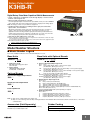
Rotary Pulse Indicator K3HB-R CSM_K3HB-R_DS_E_9_1 Digital Rotary Pulse Meter Capable of 50 kHz Measurements • Visual confirmation of judgement results through display colors that switch between red and green. *1 • Measures High-speed Pulses at 50 kHz. Provides high-speed pulse measurements up to 50 kHz of rotary encoder or ON/OFF pulse signals and can perform rotating measurement of high-speed rotating objects. Note: No-voltage contacts of up to 30 Hz are supported. • Six Measurement Operations Including Rotation (rpm)/Circumferential Speed, Ratio, and Cumulative One Rotary Pulse Meter has 6 rotary pulse measurement functions to support a variety of pulse measurement applications. Select the best function for your application from the following: Rotation (rpm)/circumferential speed/instantaneous flowrate (value proportional to frequency), absolute ratio, error ratio, error, flow rate ratio, and passing speed (value inversely proportional to frequency). • DeviceNet models added to the series. *2 *1 Visual confirmation of judgement results is not supported on models that do not have an output or models that do not support DeviceNet. You can change the display color by setting it, but you cannot switch it based on the judgement results. *2 DeviceNet models have a depth of 97 mm. Refer to Safety Precautions for All Digital Panel Meters. Model Number Structure ■ Model Number Legend Base Units and Optional Boards can be ordered individually or as sets. Base Units Base Units with Optional Boards K3HB-R @ 1 K3HB-R@-@@@ 5 1. Input Sensor Code NB: NPN input/voltage pulse input PB: PNP input 5. Supply Voltage 100-240 VAC:100 to 240 VAC 24 VAC/VDC: 24 VAC/VDC Optional Boards Sensor Power Supply/Output Boards K33-@ 2 Relay/Transistor Output Boards K34-@ 3 Event Input Boards K35-@ 4 1 2 3 4 5 2. Sensor Power Supply/Output Type Code None: None CPA: Relay output (PASS: SPDT) + Sensor power supply (12 VDC±10%, 80 mA) (See note 1.) L1A: Linear current output (0 to 20 or 4 to 20 mA DC) + Sensor power supply (12 VDC±10%, 80 mA) (See note 2.) L2A: Linear voltage output (0 to 5, 1 to 5, or 0 to 10 VDC) + Sensor power supply (12 VDC±10%, 80 mA) (See note 2.) A: Sensor power supply (12 VDC ±10%, 80 mA) FLK1A: Communications (RS-232C) + Sensor power supply (12 VDC±10%, 80 mA) (See note 2.) FLK3A: Communications (RS-485) + Sensor power supply (12 VDC±10%, 80 mA) (See note 2.) 3. Relay/Transistor Output Type Code None: None C1: Relay contact (H/L: SPDT each) C2: Relay contact (HH/H/LL/L: SPST-NO each) T1: Transistor (NPN open collector: HH/H/PASS/L/LL) T2: Transistor (PNP open collector: HH/H/PASS/L/LL) BCD *:BCD output + transistor output (NPN open collector: HH/H/PASS/L/LL) DRT: DeviceNet (See note 2.) * A Special BCD Output Cable (sold separately) is required. 4. Event Input Type Code None: None 1: 5 inputs (M3 terminal blocks), NPN open collector 2: 8 inputs (10-pin MIL connector), NPN open collector 3: 5 inputs (M3 terminal blocks), PNP open collector 4: 8 inputs (10-pin MIL connector), PNP open collector Note: 1. CPA can be combined with relay outputs only. 2. Only one of the following can be used by each Digital Indicator: RS-232C/RS-485 communications, BCD communications, or DeviceNet communications. Accessories (Sold Separately) Rubber Packing Model K32-DICN: Special Cable (for event inputs with 8-pin connector) K32-BCD: Special BCD Output Cable K32-P1 Note: Rubber packing is provided with the Controller. 1 K3HB-R Specifications ■ Ratings Supply voltage 100 to 240 VAC, 24 VAC/VDC, DeviceNet power supply: 24 VDC Allowable power supply voltage range 85% to 110% of the rated power supply voltage, DeviceNet power supply: 11 to 25 VDC Power consumption (See note 1.) 100 to 240 VAC: 18 VA max. (max. load) 24 VAC/DC: 11 VA/7 W max. (max. load) Current consumption DeviceNet power supply: 50 mA max. (24 VDC) Input No-voltage contact, voltage pulse, open collector External power supply 12 VDC ±10%, 80 mA (models with external power supply only) Event inputs (See note 2.) NPN open collector or no-voltage contact signal ON residual voltage: 2 V max. ON current at 0 Ω: 4 mA max. Max. applied voltage: 30 VDC max. OFF leakage current: 0.1 mA max. Startup compensation timer input Hold input Reset input Bank input Output ratings Relay output (depends on the model) Transistor output Linear output 250 VAC, 30 VDC, 5 A (resistive load) Mechanical life expectancy: 5,000,000 operations, Electrical life expectancy: 100,000 operations Maximum load voltage: 24 VDC, Maximum load current: 50 mA, Leakage current: 100 µA max. Linear output 0 to 20 mA DC, 4 to 20 mA DC: Load: 500 Ω max, Resolution: Approx. 10,000, Output error: ±0.5% FS Linear output 0 to 5 VDC, 1 to 5 VDC, 0 to 10 VDC: Load: 5 kΩ max, Resolution: Approx. 10,000, Output error: ±0.5% FS (1 V or less: ±0.15 V; no output for 0 V or less) Display method Negative LCD (backlit LED) display 7-segment digital display (Character height: PV: 14.2 mm (green/red); SV: 4.9 mm (green)) Main functions Scaling function, measurement operation selection, averaging, output hysteresis, output OFF delay, output test, teaching, display value selection, display color selection, key protection, bank selection, display refresh period, maximum/minimum hold, reset Ambient operating temperature −10 to 55°C (with no icing or condensation) Ambient operating humidity 25% to 85% Storage temperature −25 to 65°C (with no icing or condensation) Altitude 2,000 m max. Accessories Watertight packing, 2 fixtures, terminal cover, unit stickers, instruction manual. DeviceNet models also include a DeviceNet connector (Hirose HR31-5.08P-5SC(01)) and crimp terminals (Hirose HR31-SC-121) (See note 3.) Note: 1. DC power supply models require a control power supply capacity of approximately 1 A per Unit when power is turned ON. Particular attention is required when using two or more DC power supply models. The OMRON S8VS-series DC Power Supply Unit is recommended. 2. PNP input types are also available. 3. For K3HB-series DeviceNet models, use only the DeviceNet Connector included with the product. The crimp terminals provided are for Thin Cables. 2 K3HB-R ■ Characteristics Display range −19,999 to 99,999 Measurement accuracy (at 23±5°C) Functions F1, F6: ±0.006% rgd ±1 digit (for voltage pulse/open collector sensors) Functions F2 to F5: ±0.02% rgd ±1 digit (for voltage pulse/open collector sensors) Measurement range Functions F1 to F6: 0.5 mHz to 50 kHz (for voltage pulse/open collector sensors) Input signals Contact input (dry contact input) (30-Hz max. with ON/OFF pulse width of 15 ms min.) No contact voltage pulse (50-KHz max. with ON/OFF pulse width of 9 µs min.; ON voltage: 4.5 to 30 V; OFF voltage: −30 to 2 V; input impedance: 10 kΩ) Open collector (50-KHz max. with ON/OFF pulse width of 9 µs min.) Connectable sensors ON residual voltage: 3 V max. OFF leakage current: 1.5 mA max. Load current: Must have a switching capacity of 20 mA or higher. Must be able to properly switch load currents of 5 mA or less. Comparative output response time (transistor output) Functions F1 to F6: 100 ms max. (time until the comparative output is made when there is a forced sudden change in the input signal from 15% to 95% or 95% to 15%.) Linear output response time Functions F1 to F6: 110 ms max. (time until the final analog output value is reached when there is a forced sudden change in the input signal from 15% to 95% or 95% to 15%.) Insulation resistance 20 MΩ min. (at 500 VDC) Dielectric strength 2,300 VAC for 1 min between external terminals and case Noise immunity 100 to 240 VAC models: ±1,500 V at power supply terminals in normal or common mode (waveform with 1-ns rising edge and pulse width of 1 μs/100 ns) 24 VAC/VDC models: ±1,500 V at power supply terminals in normal or common mode (waveform with 1-ns rising edge and pulse width of 1 μs/100 ns) Vibration resistance Frequency: 10 to 55 Hz; Acceleration: 50 m/s2, 10 sweeps of 5 min each in X, Y, and Z directions Shock resistance 150 m/s2 (100 m/s2 for relay outputs) 3 times each in 3 axes, 6 directions Weight Degree of protection Approx. 300 g (Base Unit only) Front panel Conforms to NEMA 4X for indoor use (equivalent to IP66) Rear case IP20 Terminals IP00 + finger protection (VDE0106/100) Memory protection EEPROM (non-volatile memory) Number of rewrites: 100,000 Applicable standards UL61010-1, CSA C22.2 No. 1010.1 (evaluated by UL) EN61010-1 (IEC61010-1): Pollution degree 2/Overvoltage category II EN61326: 1997, A1: 1998, A2: 2001 EMC EMI: EN61326 industrial applications Electromagnetic radiation interference CISPR 11 Group 1, Class A Terminal interference voltage CISPR 11 Group 1, Class A EMS: EN61326 industrial applications Electrostatic Discharge Immunity EN61000-4-2: 4 kV (contact), 8 kV (in air) Radiated Electromagnetic Field Immunity EN61000-4-3: 10 V/m 1 kHz sine wave amplitude modulation (80 MHz to 1 GHz, 1.4 to 2 GHz) Electrical Fast Transient/Burst Noise Immunity EN61000-4-4: 2 kV (power line), 1 kV (I/O signal line) Surge Immunity EN61000-4-5: 1 kV with line (power line), 2 kV with ground (power line) Conducted Disturbance Immunity EN61000-4-6: 3 V (0.15 to 80 MHz) Power Frequency Magnetic Immunity EN61000-4-8: 30 A/m (50 Hz) continuous time Voltage Dips and Interruptions Immunity EN61000-4-11: 0.5 cycle, 0°/180°, 100% (rated voltage) 3 K3HB-R Operation ■ Functions (Operating Modes) F1 to F6 Functions F1 to F6 provide rpm/circumferential speed and other calculation displays by measuring continuous pulses (frequencies). Example Length of processing stage F1: Displays rotation (rpm) or circumferential speed for one input. F2 to F5: Displays the calculation result for two rotation (rpm) speeds. F6: Function name f1 Absolute ratio f2 Error ratio f3 Rotational difference f4 Flow rate ratio f5 Passing time f6 Function F1 Rpm/ circumferential speed/ Instantaneous flowrate The basic principle used by the Digital Indicator to calculate the rotation speed (rpm) display is to count the ON/OFF time (T) for input sensor or other device inputs using the internal system clock, and then automatically calculate the frequency. This frequency (f) is multiplied by 60 and displayed as the rotation (rpm) speed. Function No. Rpm/circumferential speed Displays the passing time calculated from the circumferential speed and the length of the processing stage for one input. Input sensor or other input pulse ON/OFF time (T) = 1 T Operation image (application) Measures frequency for input A and displays the Measuring roller winding speed rotation (rpm) or circumferential speed proportional to the input frequency. Display value D = fa × 60 × α fa: Input frequency (Hz) Calculation Display unit PASS L 1/60 N OK/NG judgment Frequency (of input pulse) Hz 1/60 kHz 1/60000 mm/s 1000 πd/60 N cm/s 100 πd/60 N m/s πd/60 N m/min πd/N km/h 0.06 πd/N l/min Check the output specifications of the input device and calculate the prescale value from the following equation: Display value D = ƒa × 60 ×α l/h H 1/N rpm rps Measuring motor speed (for product testing) Prescale value (α) Rotation speed Instantaneous flowrate Frequency (f) = • Rotation speed (rpm) = f × 60 • Circumferential speed = Roll circumference × Rotation speed (rpm) • Passing time= Length of processing stage Circumferential speed These calculations are automatically made internally and displayed whenever any input pulse is received. Operation Circumferential speed T N = Pulses per rotation πd = Circumferential length per rotation (m) F2 Absolute ratio Multiples input B divided by input A ( B ) by 100 and A displays the ratio as a percentage (%). Display unit: % Measuring the speed ratio between two rollers HH H PASS L LL Warning 4 K3HB-R Function F3 Error ratio Operation Operation image (application) Multiplies the error between input A and input B ( B −1) by 100 and displays the ratio as a percentage A (%). Display unit: % Measuring the line speed error ratio between two conveyors Communications output To computer (remote monitoring) F4 Rotational difference Displays the difference between input A and input B (B − A) as the rotation (rpm) speed error or circumferential speed error. Measuring the rotation (rpm)/circumferential speed error (absolute error) between two conveyors HH Display unit: rpm, rps, rph, Hz, kHz, mm/s, m/s m/min, km/h l/min, l/h, etc. H PASS L LL Warning F5 Flow rate ratio Displays the flow rate ratio of B from inputs A and B ( B ) as a ratio (%). A+B Display unit: % Monitoring liquid mixture flow rate ratio Linear output Recording meter F6 Passing time The passing time for the desired distance is displayed by measuring the frequency of input A. Displaying the passing time for a conveyor line Passing time (s) = 1/ƒa × α ƒa: Input frequency (Hz) Set the prescale value for the desired display unit using the following table for reference. Distance Calculation Passing time Display unit Prescale value (α) s L/(πd/N) N = Pulses per rotation πd = Circumferential length per rotation (m) L = Length of process (m) Display unit: Seconds (s), minutes (min), hours/minutes/seconds (h.min.s), minutes/seconds/tenths of seconds (min.s.1/10s), etc. H PASS L Warning output 5 K3HB-R ■ What Is Prescaling? ■ What Is the Auto-zero Function? To make calculations using the input pulse to display rotation (rpm) or circumferential speed, the number of pulses per rotation or the length of the circumference must be multiplied by a certain coefficient. This coefficient is called the prescale value. K3HB-R (Set this function before using the Digital Indicator.) If a function f1 to f6 is set, the frequency can be force-set to zero if there is no input pulse for a set period. This period is called the autozero time. Set the auto-zero time to slightly longer than the longest input pulse interval. (The display will not easily return to zero if the auto-zero time is too long or left at the default setting.) Time Unit Settings Proximity sensor Setting Rotation speed (rpm) = f × 60 × a f: Input pulse frequency (No. of pulses per second) a: Prescale value If there are 5 pulses per rotation, then a = 1/5 (= 0.2 = 2 × 10⁻¹) and an accurate rotation speed (rpm) can be calculated. -1 The actual setting is X = 2.0000 (mantissa) and Y = 10 (exponent). Meaning scal Prescale value menu setting min Minute display h.mm.ss h.mm.ss display mm.ss.d mm.ss.d display (d = tenths of a second) Note: Time unit can be set only when passing time (F6) is selected. Input Type Setting NO: Voltage pulse high NC: Voltage pulse low No-contact or voltage pulse input 00 01 Contact 10 11 Note: Set to 10 or 11 when there is a large variation in the display. The largest measurement range is 30 Hz. 6 K3HB-R Common Specifications ■ Event Input Ratings K3HB-R S-TMR, HOLD, RESET, BANK1, BANK2, BANK4 Contact ON: 1 kΩ max., OFF: 100 kΩ min. No-contact ON residual voltage: 2 V max. OFF leakage current: 0.1 mA max. Load current: 4 mA max. Maximum applied voltage: 30 VDC max. ■ Output Ratings Contact Output Item Transistor Outputs Resistive loads (250 VAC, cosφ=1; 30 VDC, L/R=0 ms) Rated load 5 A at 250 VAC 5 A at 30 VDC Mechanical life expectancy 5,000,000 operations Electrical life expectancy 100,000 operations Inductive loads (250 VAC, closed circuit, cosφ=0.4; 30 VDC, L/R=7 ms) Maximum load voltage 24 VDC Maximum load current 50 mA 100 µA max. Leakage current 1 A at 250 VAC 1 A at 30 VDC Linear Output Item Outputs 0 to 20 mA Allowable load impedance 500 Ω max. Resolution Approx. 10,000 Output error ±0.5% FS 4 to 20 mA 0 to 5 V Type RS-232C, RS-485 Communications method Half duplex Synchronization method Start-stop synchronization (asynchronous) Baud rate 9600/19200/38400 bps Transmission code ASCII Data length 7 bits or 8 bits Stop bit length 2 bits or 1 bit Error detection Vertical parity and FCS Parity check Odd, even 0 to 10 V ±0.5% FS (±0.15 V for 1 V or less and no output for 0 V) Serial Communications Output Item 1 to 5 V 5 kΩ min. BCD Output I/O Ratings (Input Signal Logic: Negative) I/O signal name Inputs REQUEST HOLD MAX MIN RESET Item Input signal Input current for no-voltage input 10 mA Signal level ON voltage OFF voltage Outputs DATA Maximum load voltage POLARITY OVER Maximum load current DATA VALID RUN Leakage current HH H PASS L LL Rating No-voltage contact input 1.5 V max. 3 V min. 24 VDC 10 mA 100 µA max. Maximum load voltage 24 VDC Maximum load current 50 mA Leakage current 100 µA max. Refer to the K3HB Communications User's Manual (Cat. No. N129) for details on serial and DeviceNet communications. 7 K3HB-R DeviceNet Communications Communications protocol Supported Remote I/O communications communications Conforms to DeviceNet Master-Slave connection (polling, bit-strobe, COS, cyclic) Conforms to DeviceNet communications standards. I/O allocations Allocate any I/O data using the Configurator. Allocate any data, such as DeviceNet-specific parameters and variable area for Digital Indicators. Input area: 2 blocks, 60 words max. Output area: 1 block, 29 words max. (The first word in the area is always allocated for the Output Execution Enabled Flags.) Message communications Explicit message communications CompoWay/F communications commands can be executed (using explicit message communications) Connection methods Combination of multi-drop and T-branch connections (for trunk and drop lines) Baud rate DeviceNet: 500, 250, or 125 Kbps (automatic follow-up) Communications media Special 5-wire cable (2 signal lines, 2 power supply lines, 1 shield line) Communications distance Baud rate Network length (max.) Drop line length (max.) Total drop line length (max.) 500 Kbps 100 m max. (100 m max.) 6 m max. 39 m max. 250 Kbps 100 m max. (250 m max.) 6 m max. 78 m max. 125 Kbps 100 m max. (500 m max.) 6 m max. 156 m max. The values in parentheses are for Thick Cable. Communications power supply 24-VDC DeviceNet power supply Allowable voltage fluctuation range 11 to 25-VDC DeviceNet power supply Current consumption 50 mA max. (24 VDC) Maximum number of nodes 64 (DeviceNet Configurator is counted as one node when connected.) Maximum number of slaves 63 Error control checks CRC errors DeviceNet power supply Supplied from DeviceNet communications connector 8 K3HB-R 9 K3HB-R Connections ■ External Connection Diagrams Terminal Arrangements Note: Refer to Internal Block Diagram on page 12 for information on isolation. A Operating Power Supply A B C D E 1 2 3 100 to 240 VAC 24 VAC/VDC 4 5 6 A1 A2 *Check the required power supply type. B Sensor Power Supply/Output Sensor power supply + PASS output C Relays, Transistors, BCD and DeviceNet B1 Relay Outputs <C1> B2 B3 N/C B4 C1 B5 Sensor 12 VDC 80 mA H <CPA> + 0-5/1-5/ 0-10 V N/C N/C 0-20/ 4-20 mA <L2A> Transistor Outputs <T1> <T2> HH C1 HH C1 H C2 H C2 NPN DeviceNet Connector (Included) <DRT> PNP power B6 supply Sensor power supply + linear output 12 VDC 80 mA C2 Relay Outputs <C2> 1 2 3 4 5 PASS 12 VDC 80 mA L C3 COM C3 C4 L C4 L C4 C5 LL C5 LL C5 C6 B1 PASS C3 COM C6 COM C6 − B2 + B3 − B4 + B5 Sensor power − B6 supply BCD (NPN Open Collector): <BCD> 1: V− (Power supply cable: Black) 2: CAN L (Communications cable: Blue) 3: Shield 4: CAN H (Communications cable: White) 5: V+ (Power supply cable: Red) Applicable Connector: HR31-5.08P-5SC (01) (HIROSE ELECTRIC CO., LTD.) * Attach the provided crimp terminals. Applicable Connector (Sold separately) K32-BCD (OMRON) (HDR-E50MAG1 with 0.3-m cable) <L1A> Sensor power supply B1 The BCD COMMON is shared. The pins indicated in the above diagram as blank (white) boxes have been removed. *Only one of the following can be used for each Digital Indicator: communications, BCD, or DeviceNet. B2 N/C B3 B4 + 12 VDC 80 mA Contact Outputs B5 Sensor power − Transistor Outputs (NPN Open Collector) B6 supply 5V <A> Sensor power supply + communications HH HH H H L L B (+) SD B1 A (−) RD B2 LL LL B (+) SG B3 PASS PASS A (−) N/C B4 12 VDC 80 mA 12 VDC 80 mA + power − RS-485 <FLK3A> RS-232C <FLK1A> B5 Sensor B6 supply Safety Standards Conformance Always use a EN/IEC-compliant power supply with reinforced insulation or double insulation for the DeviceNet power supply. The product must be used indoors for the above applicable standards to apply. 10 K3HB-R NPN Input Model E Pulse Inputs E1 E1 E2 NPN Input B Voltage 700 Ω 700 Ω Input A PNP E3, E6 E3 COM E4 E4 NPN Input B PNP E6 COM Note: E3 and E6, as well as B6, are internally connected. 510 Ω E2, E5 COM E3 COM E5 510 Ω PNP Input: K3HB-@PB E2 12 V COM E2, E5 Voltage Input A E3, E6 12 V • Rotary Pulse Meter: K3HB-R NPN Input: K3HB-@NB PNP Input Model • NPN input section • Voltage pulse input section 12 V E5 510 Ω E6 COM E1, E4 10 kΩ Note: E3 and E6, as well as B5, are internally connected. 700 Ω E3, E6 D Event Inputs Models with Terminal Blocks <1> <3> N/C S-TMR HOLD RESET N/C COM • Use terminal pin D6 as the common terminal. • Use NPN open collector or no-voltage contacts for event input. PNP types are also available. Models with Connectors <2> <4> 1: N/C 3: HOLD 5: N/C 7: BANK4 9: BANK1 1 9 2: S-TMR 4: RESET 6: COM 8: BANK2 10 10: COM 2 12 V S-TMR: D2 HOLD: D3 RESET: D4 4.7 kΩ • Applicable Connector (Sold separately) XG4M-1030 (OMRON) • Special Cable (Sold separately) K32-DICN (OMRON) (XG4M-1030 with 3-m cable) 3.9 kΩ D6 COM BCD Output Cable Model Shape Pin arrangement K32-BCD Connected device end (PLC, display device, etc.) K3HB end 300 mm 38 mm Cover: HDR-E50LPA5 (manufactured by Honda Tsushin Co., Ltd.) Connector: HDR-E50MAG1 (manufactured by Honda Tsushin Co., Ltd.) 46.5 mm D-sub connector (37-pin female) Cover: 17JE-37H-1A (manufactured by DDK) Connector: Equivalent to 17JE-13370-02 (manufactured by DDK) Stud: 17L-002A (manufactured by DDK) COMMON 1 1 100 2 4 8 1 2 101 4 8 1 2 102 4 8 1 3 10 2 4 8 1 104 2 2 3 4 5 6 7 8 9 10 11 12 13 14 15 16 17 18 19 20 21 22 23 24 25 26 27 28 29 30 31 32 33 34 35 36 37 4 104 8 OVER DATA VALID RUN COMMON REQUEST MAX REQ. MIN REQ. HOLD RESET POLARITY HH H PASS L LL COMMON Note: The BCD Output Cable has a D-sub plug. Cover: 17JE-37H-1A (manufactured by DDK); Connector: equivalent to 17JE-23370-02 (D1) (manufactured by DDK) Special Cable (for Event Inputs with 8-pin Connector) Model Appearance K32-DICN 9 10 1 2 Cable marking 3,000 mm (3 m) Wiring Pin No. 1 2 3 4 5 6 7 8 9 10 Signal name N/C S-TMR HOLD RESET N/C COM BANK4 BANK2 BANK1 COM 11 K3HB-R ■ Derating Curve for Sensor Power Supply (Reference Values) Maximum current (mA) For 12V 140 1 120 100 80 60 40 20 0 −20 −10 0 10 20 30 40 50 60 Ambient temperature (°C) Note: 1. The above values were obtained under test conditions with the standard mounting. The derating curve will vary with the mounting conditions, so be sure to adjust accordingly. 2. Internal components may be deteriorated or damaged. Do not use the Digital Indicator outside of the derating range (i.e., do not use it in the area labeled A, above). ■ Internal Block Diagram Waveform shaping circuit Keys EEPROM Indications • Input circuit • Output circuit • Transistor output circuit Drive circuit Drive circuit Event input Digital input circuit Waveform shaping circuit Linear output Linear output circuit Drive circuit Sensor power supply Filter Pulse input Pulse input circuit BCD BCD I/O Microcomputer VO Drive circuit Transistor output Relay output X Drive circuit DeviceNet circuit DeviceNet Drive circuit Communications driver Communications VCOM VDD Power supply circuit (isolated) VO DC-DC Converter (isolated) Power supply 12 K3HB-R ■ BCD Output Timing Chart A REQUEST signal from a Programmable Controller or other external device is required to read BCD data. Single Sampling Data Output Continuous Data Output 20-ms pulse min. (50 ms max.) REQ. MAX.MIN. REQ. MAX.MIN. DATA DATA All data "High" All data "High" Data 1 Data 2 All data "High" Data DATA VALID DATA VALID Approx. 30 ms 40 ms 40 ms Approx. 30 ms 16 ms The data is set in approximately 30 ms from the rising edge of the REQUEST signal and the DATA VALID signal is output. When reading the data from a Programmable Controller, start reading the data when the DATA VALID signal turns ON. The DATA VALID signal will turn OFF 40 ms later, and the data will turn OFF 16 ms after that. 24 ms 64 ms 40 ms 24 ms 64 ms Measurement data is output every 64 ms while the REQUEST signal remains ON. Note: If HOLD is executed when switching between data 1 and data 2, either data 1 or data 2 is output depending on the timing of the hold signal. The data will not go LOW. • The K3HB BCD output model has an open collector output, so wired OR connection is possible REQ. (1) K3HB (1) Programmable Controller REQ. (2) K3HB (2) REQ. (3) DATA (including POL and OVER) and DATA VALID can be used in a wired OR. RUN, HH, H, PASS, L, and LL are always output, with or without a REQUEST signal. Do not used a wired OR connect for these signals. K3HB (3) (1) DATA (2) (3) DATA VALID (See note.) (See note.) (See note.) Note: Leave 20 ms min. between DATA VALID turning OFF and the REQUEST signal. Programmable Controller Connection Example Digital Indicator SYSMAC Programmable Controller DC Input Unit Connector pin No. (See note.) 1.COMMON 2.1 3.2 IN 2.1 IN 3.2 10° 5.8 Connector pin No. (See note.) 1.COMMON COM Internal circuit 4.4 Display Unit Connection Example Digital Indicator IN IN 4.4 5.8 23.DATA VALID 24.RUN 10° 23.DATA VALID IN 24.RUN IN To 101 To 102 240 Ω 240 Ω 240 Ω 25.COMMON Short26.REQUEST circuit 240 Ω Internal circuit +5 V Transistor Output Unit OUT 30.RESET OUT 31.POLARITY (+/− polarity) COM (0 V) +5 V 240 Ω 240 Ω 30.RESET 240 Ω 240 Ω 24 VDC 31.POLARITY (+/− polarity) V O D C B A DP LE V O D C B A DP LE V O D C B A DP LE V O 26.REQUEST Internal circuit 25.COMMON 8 8 8 SEC M7E-01D@N2, 01H@N2 +24 V 0V <M7E Digital Display Unit> DC power supply Note: The BCD output connector pin number is the D-sub connector pin number when the BCD Output Cable (sold separately) is connected. This number differs from the pin number for the Digital Indicator narrow pitch connector (manufactured by Honda Tsushin Kogyo Co., Ltd.). Refer to the following User's Manual for application precautions and other information required when using the Digital Indicator: K3HB-R/P/C Digital Indicator User's Manual (Cat. No. N136) The manual can be downloaded from the following site in PDF format: OMRON Industrial Web http://www.fa.omron.co.jp 13 K3HB-R ■ Component Names and Functions Max./Min. status indicator PV display Turns ON when the maximum value or minimum value is displayed in the RUN level. Displays PVs, maximum values, minimum values, parameter names, and error names. Level/bank display Position meter In RUN level, displays the bank if the bank function is ON. (Turns OFF if the bank function is OFF.) In other levels, displays the current level. Displays the position of the PV with respect to a desired scale. Comparative output status indicators SV display Display the status of comparative outputs. HH H P L Displays SV and monitor values. Max Min B L CMW Hold LL T HH H LL L Status indicators Display SV display status indicators MAX/MIN Function CMW Lit when communications writing is ON (enabled) and not lit when OFF (prohibited). Hold Turns ON/OFF when HOLD input turns ON/OFF. MAX/MIN Key Used to switch the display between the PV, maximum value, and minimum value and to reset the maximum and minimum values. LEVEL Key Used to switch level. LEVEL MODE SHIFT UP Indicator T MODE Key Used to switch the parameters displayed. HH H LL L T HH, H, L, LL SHIFT Key Used to change parameter settings. When changing a set value, this key is used to move along the digits. Function Turns ON when parameters for which teaching can be performed are displayed. In RUN level, turn ON when the comparative set value HH, H, L, or LL is displayed. UP Key When changing a set value, this key is used to change the actual value. When a measurement value is displayed, this key is used to execute or clear the forced-zero function or to execute teaching. 14 K3HB-R ■ Dimensions 101.2 91 Terminal cover (included) Panel Cutout Dimensions Character Size for Main Display (mm) PV display SV display 120 min. 4.9 14.2 100 3.5 (112) 7.6 75 min. 92+0.8 0 45+0.6 0 12 1.3 95 * 2 96 Mounting Recommended Panel Thickness 1 to 8 mm. Mount the product horizontally. 44.8 48 *DeviceNet models: 97 mm Terminal: M3, Terminal Cover: Accessory Wiring Precautions Mounting Method • For terminal blocks, use the crimp terminals suitable for M3 screws. • Tighten the terminal screws to the recommended tightening torque of approx. 0.5 N·m. • To prevent inductive noise, separate the wiring for signal lines from that for power lines. 1. Insert the K3HB into the mounting cutout in the panel. 2. Insert watertight packing around the Unit to make the mounting watertight. Watertight packing Wiring • Use the crimp terminals suitable for M3 screws shown below. 5.8 mm max. 5.8 mm max. Unit Stickers (included) 3. Insert the adapter into the grooves on the left and right sides of the rear case and push until it reaches the panel and is fixed in place. Adaptor • No unit stickers are attached to the Digital Indicator. • Select the appropriate units from the unit sticker sheets provided. LCD Field of Vision The K3HB is designed to have the best visibility at the angles shown in the following diagram. Note: For measurements for commercial purposes, be sure to use the unit required by any applicable laws or regulations. 10° 30° Rubber Packing (Sold Separately) K32-P1 If the rubber packing is lost or damaged, it can be ordered using the following model number: K32-P1. (Depending on the operating environment, deterioration, contraction, or hardening of the rubber packing may occur and so, in order to ensure the level of waterproofing specified in NEMA4, periodic replacement is recommended.) Note: Rubber packing is provided with the Controller. 15 K3HB-R Main Functions ■ Main Functions and Features Measurement Function Input Compensation func The K3HB-R has the following six functions for receiving and displaying input pulses. F1: Rotation (rpm)/circumferential speed Auto-zero Times at.za, at.zb The frequency is forced to zero if there is no pulse input for a set period. F2: Absolute ratio Key Operations F3: Error ratio Teaching F4: Rotational difference The present measurement value can be used as a scaling value. F5: Flow rate ratio F6: Passing time Key Protection The K3HB-P has the following six functions for receiving and displaying input pulses. Key protection restricts level or parameter changes using the keys to prevent unintentional key operations and malfunctions. F1: Passing speed F2: Cycle F3: Time difference F4: Time band F5: Measuring length F6: Interval The K3HB-C has the following three functions for receiving and displaying input pulses. F1: Individual inputs F2: Phase differential inputs F3: Pulse counting input Filters Average Processing avg-t, avg-n Average processing of input signals with extreme changes or noise smooths out the display and makes control stable. Input Types in-ta, in-tb Specify the types of sensor connected to input A and input B. 16 K3HB-R Outputs Display Comparative Output Pattern out-p Standard, zone, and level comparative output patterns can be selected for comparative outputs. hys Hysteresis Prevents comparative outputs from chattering when the measurement value fluctuates slightly near the set value. Output Refresh Stop o-stp Holds the output status when a comparative result output other than PASS turns ON. PASS Output Change pass Comparative results other than PASS and error signals can be output from the PASS output terminal. Output OFF Delay off-d Delays turning OFF comparatives for a set period. This can be used to provide sufficient time to read the comparative output ON status when the comparative result changes at short intervals. Display Value Selection The display value can be set to the present value, the maximum value, or the minimum value. Display Color Selection Turns ON the comparative output for a specific time. out-n Output Logic Reverses the output logic of comparative results. Startup Compensation Timer s-tmr Measurements can be stopped for a set time using an external input. color The present value display color can be set to green or red. The color of the present value can also be switched according to the comparative output. Display Refresh Period d.ref When the input changes rapidly, the display refresh period can be lengthened to control flickering and make the display easier to read. Position Meter pos-t, pos-h, pos-l The present measurement value can be displayed as a position in relation to the scaling width on a 20-gradation position meter. Prescale ps.ax, ps.ay, ps.bx, ps.by The input signal can be converted and displayed as any value. Comparative Set Value Display shot Shot Output disp sv.dsp Select whether or not to display the comparative value during operation. Display auto-return ret Automatically returns the display to RUN level when there are no key operations (e.g., max./min. switching, bank settings using keys). Other Max./Min. Hold Holds the maximum and minimum measurement values. test Output Test Output operation can be checked without using actual input signals by using the keys to set a test measurement value. lset.c, lset.v, lset.h, lset.l Linear Outputs A current or voltage proportional to the change in the measurement value can be output. Standby Sequence stdby Bank Selection bnk-c Switch between 8 comparative value banks using the keys on the front panel or external inputs. A set of set comparative values can be selected as a group. Bank Copy copy Any bank settings can be copied to all banks. The comparison outputs can be kept OFF until the measurement value enters the PASS range. ALL DIMENSIONS SHOWN ARE IN MILLIMETERS. To convert millimeters into inches, multiply by 0.03937. To convert grams into ounces, multiply by 0.03527. In the interest of product improvement, specifications are subject to change without notice. 17 Read and Understand This Catalog Please read and understand this catalog before purchasing the products. Please consult your OMRON representative if you have any questions or comments. Warranty and Limitations of Liability WARRANTY OMRON's exclusive warranty is that the products are free from defects in materials and workmanship for a period of one year (or other period if specified) from date of sale by OMRON. OMRON MAKES NO WARRANTY OR REPRESENTATION, EXPRESS OR IMPLIED, REGARDING NON-INFRINGEMENT, MERCHANTABILITY, OR FITNESS FOR PARTICULAR PURPOSE OF THE PRODUCTS. ANY BUYER OR USER ACKNOWLEDGES THAT THE BUYER OR USER ALONE HAS DETERMINED THAT THE PRODUCTS WILL SUITABLY MEET THE REQUIREMENTS OF THEIR INTENDED USE. OMRON DISCLAIMS ALL OTHER WARRANTIES, EXPRESS OR IMPLIED. LIMITATIONS OF LIABILITY OMRON SHALL NOT BE RESPONSIBLE FOR SPECIAL, INDIRECT, OR CONSEQUENTIAL DAMAGES, LOSS OF PROFITS OR COMMERCIAL LOSS IN ANY WAY CONNECTED WITH THE PRODUCTS, WHETHER SUCH CLAIM IS BASED ON CONTRACT, WARRANTY, NEGLIGENCE, OR STRICT LIABILITY. In no event shall the responsibility of OMRON for any act exceed the individual price of the product on which liability is asserted. IN NO EVENT SHALL OMRON BE RESPONSIBLE FOR WARRANTY, REPAIR, OR OTHER CLAIMS REGARDING THE PRODUCTS UNLESS OMRON'S ANALYSIS CONFIRMS THAT THE PRODUCTS WERE PROPERLY HANDLED, STORED, INSTALLED, AND MAINTAINED AND NOT SUBJECT TO CONTAMINATION, ABUSE, MISUSE, OR INAPPROPRIATE MODIFICATION OR REPAIR. Application Considerations SUITABILITY FOR USE OMRON shall not be responsible for conformity with any standards, codes, or regulations that apply to the combination of products in the customer's application or use of the products. At the customer's request, OMRON will provide applicable third party certification documents identifying ratings and limitations of use that apply to the products. This information by itself is not sufficient for a complete determination of the suitability of the products in combination with the end product, machine, system, or other application or use. The following are some examples of applications for which particular attention must be given. This is not intended to be an exhaustive list of all possible uses of the products, nor is it intended to imply that the uses listed may be suitable for the products: Outdoor use, uses involving potential chemical contamination or electrical interference, or conditions or uses not described in this catalog. Nuclear energy control systems, combustion systems, railroad systems, aviation systems, medical equipment, amusement machines, vehicles, safety equipment, and installations subject to separate industry or government regulations. Systems, machines, and equipment that could present a risk to life or property. Please know and observe all prohibitions of use applicable to the products. NEVER USE THE PRODUCTS FOR AN APPLICATION INVOLVING SERIOUS RISK TO LIFE OR PROPERTY WITHOUT ENSURING THAT THE SYSTEM AS A WHOLE HAS BEEN DESIGNED TO ADDRESS THE RISKS, AND THAT THE OMRON PRODUCTS ARE PROPERLY RATED AND INSTALLED FOR THE INTENDED USE WITHIN THE OVERALL EQUIPMENT OR SYSTEM. PROGRAMMABLE PRODUCTS OMRON shall not be responsible for the user's programming of a programmable product, or any consequence thereof. Disclaimers CHANGE IN SPECIFICATIONS Product specifications and accessories may be changed at any time based on improvements and other reasons. It is our practice to change model numbers when published ratings or features are changed, or when significant construction changes are made. However, some specifications of the products may be changed without any notice. When in doubt, special model numbers may be assigned to fix or establish key specifications for your application on your request. Please consult with your OMRON representative at any time to confirm actual specifications of purchased products. DIMENSIONS AND WEIGHTS Dimensions and weights are nominal and are not to be used for manufacturing purposes, even when tolerances are shown. PERFORMANCE DATA Performance data given in this catalog is provided as a guide for the user in determining suitability and does not constitute a warranty. It may represent the result of OMRON’s test conditions, and the users must correlate it to actual application requirements. Actual performance is subject to the OMRON Warranty and Limitations of Liability. ERRORS AND OMISSIONS The information in this document has been carefully checked and is believed to be accurate; however, no responsibility is assumed for clerical, typographical, or proofreading errors, or omissions. 2012.4 In the interest of product improvement, specifications are subject to change without notice. OMRON Corporation Industrial Automation Company http://www.ia.omron.com/ (c)Copyright OMRON Corporation 2012 All Right Reserved.