1
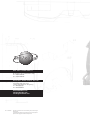
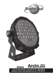
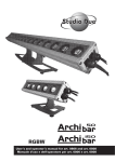
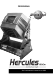
INTERNATIONAL PATENT WO99/40361
User’s and operator’s manual for art. 0004•0203
Manuale d’uso e dell’operatore per art. 0004•0203
IP•54
1800W / 1200W
ENGLISH INDEX
Safety informations ........................................................................................................................... page 1
Technical features.............................................................................................................................. page 2
Before using....................................................................................................................................... page 3
Lamp installation, replacement and setting .................................................................................... page 4
Installation of the dust proof filters .................................................................................................. page 5
Control panel and configuration ...................................................................................................... page 6
Use of the CityBeam in DMX 512 ..................................................................................................... page 8
DMX signal connection..................................................................................................................... page 9
DMX line and termination ................................................................................................................. page 10
Automode functioning ..................................................................................................................... page 11
Troubleshooting guide ...................................................................................................................... page 12
System board connection................................................................................................................. page 14
Electric diagrams .............................................................................................................................. page I
Components and parts
................................................................................................................. page VII
Technical drawings............................................................................................................................ page VIII
Appendix A (DMX values) ................................................................................................................ page XI
1800W / 1200W
INTERNATIONAL PATENT WO99/40361
IP•54
Appendix B (games).......................................................................................................................... page XII
!
WARNING
SAFETY INFORMATION
READ ALL CAUTIONS AND WARNINGS PRIOR TO OPERATE THIS EQUIPMENT.
INSTRUCTION TO PREVENT INJURY OR DAMAGE DUE TO ELECTRIC SHOCK, FIRE, MECHANICAL HAZARDS AND
UV RADIATION HAZARDS.
• PROTECTION AGAINTS FIRE
1) This equipment is designed for use with the following lamps only: MSD 1200W (art.0004) MSR 1800W (art.0203).
DO NOT USE ANY OTHER TYPE LAMP!
2) Maintain minimum distance of 0.5 meter from walls or any other type flammable surfaces.
3) Maintain minimum distance to lighted objects of 5.0 meter.
4) Replace fuses only with the specified type and rating.
5) Do not install the spot close to heat sources. Do not lay the connection cable on the spot when it is warm.
• PROTECTION AGAINST ELECTRIC SHOCK
1) This equipment must be earthed.
2) Class I equipment. The power supply cord includes a protective earthing conductor as part of the cord.
3) For connection to the supply mains proceed as pict.1 page 3. The equipment must be connected to branch circuit having a
circuit- breacker In=16A Id=0.03A (230VAC)
4) Disconnect power before lamp’s replacement or servicing (service personnel).
• PROTECTION AGAINST MECHANICAL HAZARDS
1) Use secondary safety chain when fixing this equipment.
2) Hot lamp explosion hazard. Do not open the equipment for 300 seconds after switching off.
3) Equipment surface may reach temperature up to 100°C. Allow about five minutes before handling.
4) Replace the lamp if it is damaged or thermally deformed.
• PROTECTION AGAINST UV RADIATION HAZARDS
1) Do not start on this equipment without lamp enclosure or if the protection screens, or ultraviolets screens are damaged.
2) The protection screens, the lenses, or the ultraviolet filters must be replaced if they are visibly damaged and their effectiveness
has been reduced, for example, by cracks or deep scratches.
3) Do not look directly at the lamp while lamp is on.
INTRODUCTION
Thank you for using the CityBeam !
The CityBeam projects, thanks to an extremely efficient optic system (international patent n. WO99/40361), a powerful light beam which
can create numberless color shades. Its performances, in terms of luminousity and lighted surfaces, can reach incredible levels.
The CityBeam IP54 comes in two versions:
• Art. 0004
• Art. 0203
CITYBEAM for MSD 1200W discharge lamp
CITYBEAM for MSR 1800W discharge lamp
The CityBeam can work in automatic mode or in synchro mode, otherwise may be controlled by 8 bit DMX controllers
The input protocol is the DMX 512. To drive the CityBeam we suggest to use either our controller DMX Control Spot, the
Control Show 512 the Easy Control or the Fancy.
To make the most of its possibilites and for a correct functioning of this unit in the years to come, we suggest you to read carefully
this manual before connecting or putting the spot into use. By doing so you will gain experience with its commands and connections
and you will be easily able to use it.
... 1 ...
YOUR REFERENCE
Always remember to give the serial number and to specify the model any time you address the seller for information or assistance.
BASIC KIT
The basic kit of the CityBeam flood projector consist of:
•Projector
•Frosted glass
•User’s manual
•Power connector
•Studio Due warranty
Available on request:
•Lamp
!
WARNING
Check that the spot has not been damaged during transport. If it has been damaged or it does not work, address
the seller. Whether the spot has been shipped to you directly, please contact the shipping company.
Only the consignee (person or company) can claim for these damages.
TECHNICAL FEATURES (CITYBEAM discharge lamp 1200W • art. 0004)
•LAMP
discharge lamp MSD 1200W
Burning position: Universal
Colour temperature: 6000K
Lamp life (hours): 2000
•COLORS
CYM color mixing continuously variable (256 steps)
•DIMMER
0-100% continuously variable (256 steps)
•BEAM ANGLE
Continuously variable (256 steps)
Spot: 8° - 11° •Flood: 15° - 20°
•POWER INPUT
Rated voltage: 230Vac 50Hz; 230Vac 60Hz
On request: 208Vac 60Hz; 200Vac 50Hz
Rated power: 1600 VA
Rated current: 7A (230Vac)
TECHNICAL FEATURES (CITYBEAM discharge lamp 2500W • art. 0003 - art. 0006)
•LAMP
discharge lamp MSR 1800W
Burning position: Universal
Colour temperature: 6000K
Lamp life (hours): 750
•COLORS
CYM color mixing continuously variable (256 steps)
•DIMMER
0-100% continuously variable (256 steps)
Colour temperature: 6000K
Lamp life (hours): 2000
•BEAM ANGLE
Continuously variable (256 steps)
Spot: 5° - 8° •Flood: 11° - 14°
•POWER INPUT
Rated voltage: 230Vac 50Hz; 230Vac 60Hz
On request: 208Vac 60Hz; 200Vac 50Hz
Rated power: 2200 VA
Rated current: 10A (230Vac)
... 2 ...
CIRCUIT - BREAKER
3 PIN CONNECTOR FOR POWER INPUT
MAINS VOLTAGE
In
Id
230V
32A
0.03A
®
L = 1) NEUTRAL
N = 2) LIVE
= 3) EARTH
CITYBEAM 1800W
art. 0203
Keep at least a distance of 0.5mt between the apparatus
and inflammable surface nearby
Disconnect the unit from power before servicing
230 VAC ; 10A - 50 Hz
QC
SN
Keep
230
®
at lea
st a
CIT
Disco
dis
YB
nnectand infltance
EA
the ammaof 0.5
M
; 14 unit fromble surmt betwe 1800art.
Ae en the W 0203
60 Hz powerfac
befornearby appa
rat
e ser
SN
vicing us
VAC
QC
CONDUCTOR SIZES (length < 20mt.)
MAINS VOLTAGE
230V
CROSS SELECTIONAL AREAS
3 x 1.5 mm 2 (minimum)
INPUT CONNECTOR IP 67
pict.1
BEFORE USING
!
WARNING
The equipment must be earthed.
IP 54 grade: the equipment must be installed on the horizontal
plane.
Read all cautions and warnings to page 1 prior to install this equipment. Particularly, read the follow:
1) Disconnect power before lamp’s replacement or servicing (service personnel)
2) Do not open the lamp cover for 300 seconds after switching off
3) Wear gloves and goggles to re-lamping or to work inside the unit (service personnel)
Before connecting the equipment to the power system: make sure that the mains voltage and frequency correspond to rated
values.
• The CityBeam can be equipped for a mains voltage 230VAC, 50 or 60Hz
on request: 208Vac, 60Hz; 200Vac, 50Hz
For a power supply of 100V-120V it is necessary to use one auto transformer with the following features:
• Output voltage 230V
• Output current 15A
The power supply cords construction is shown in pict.1. For connection to the mains supply proceed as pict.1.
The equipment must be connected to branch circuit having a circuit-breacker In=16A • Id=0.03A (230VAC)
a) Do not install the spot close to the heat sources. Observe minimum distance between the spots of 1.5 meters. Do not lay the
connection cable on the spot when it is warm.
b) This unit must be positioned as to allow its ventilation. Be careful not to acclude the in-out ventilating grilles.
c) The unit must be positioned at least 50cm. from walls or other flammable surfaces.
d) Observe minimum distance to lighted objects of 5 meters.
External surface temperature Ta 35°C:
• After 5 minutes work; Tc=75°C.
• Once the thermic balance has been obtained; Tc=100°C.
4) The protection screens, the lenses, or the ultraviolet filters must be replaced if they are visibly damaged and their effectiveness
has been reduced, for example, by cracks or deep scratches.
5) The lamp must be replaced if it has been damaged or thermally deformed.
6) Clean regularly the in-out ventilating grilles.
7) Do not handle the spot by taking it by the head, but always by using the special handles.
... 3 ...
G
pict.2
A
B
E
C
!
WARNING
In case of replacement of the lamp or maintenance, do not open
the fixture unless 5 minutes have passed from the switching off.
This operation has to be done when the apparatus is disconnected
from the mains supply
INSTALLATION OF THE DISCHARGE LAMP MSD 1200W, MSR 1800W (art. 0004 - 0203)
(see pic.2)
1)
2)
3)
4)
5)
Disconnect power before lamp’ s replacement. Wear gloves and goggles.
Remove completely the pommels (A) on the base of the head
Open the base of the lamp room (G)
Unscrew the four pawls (C) and remove the parabole
Insert the lamp into the lampholder (E)
Do not touch the quarz bulb with fingers. If this happenes, clean the bulb before use with dry cloth and alcohol.
6) Insert the parabole (B)
7) Screw the four pawls to fix it (C)
8) Close the rear panel and install again the two pommels (A) and hold them tightly.
... 4 ...
IP RATE
The declared IP rate of the CityBeam comes supported at these conditions:
• the installation of the fixture on a wide and stable surface
• the air cooling input and output are located on the base of the side-shell,
it is not possible to install the fixture outdoor with the ballast upwards
• you must use the filter supplied with the basic kit for the IP RATE 54
!
WARNING
The CityBeam has a IP rate 44 without filters installed and an IP RATE 54 with filters installed.
You must use the filters in critical working conditions and, normally, when the fixture works outdoor.
You must remove the filters when the ambient temperature is over 35°C.
You must regularly clean the filters to allow the correct cooling of the fixture.
INSTALLATION OF THE DUST PROOF FILTERS
!
WARNING
You must operate with power supply disconnected from the fixture
You must remove the two side protective shells. The
two filters must be assembled on the bulkheads at the
bottom of the side brackets.
pict.3
Pay attention to the installation: dust proof filters
must stick correctly to prevent the entrance of the
dust. You must control that the two filters completely cover the overall of the air entrance.
... 5 ...
CONTROL PANEL
LAMP DIMMER
LAMP OFF
DMX
MENU
UP
DOWN
ENTER
pict.4
CONTROL PANEL
On the control panel of the CityBeam (pict.4) you can find, besides the display, the leds and the buttons to use to set the spot.
LED
• “DMX” led
• ”LAMP” led
flashing:
DMX input present
off:
no DMX input
flashing:
the lamp switching off is remotely controlled
off:
lamp switched on
• ”DIMMER” led flashing:
the lamp is 33% dimmered
off:
lamp switched on
BUTTONS
Four buttons are used to programme the spot:
• MENU
• DOWN
• UP
• ENTER
to select the programming options
to go backward in the selected options
to go forward in the selected options
to confirm the selected options
DISPLAY
Shows the various menus and the selected options.
... 6 ...
SUMMARY OF THE PROGRAMMING FUNCTIONS OF THE CITYBEAM
Addr
nChn
FOCU
teSt
Mode
LHrS
FLIP
FHrS
rSEt
About twenty seconds after the switching on, the number of the software version will be shown on the display in “X_00” format.
Afterwards the first of the nine available menus will appear:
Addr
Mode
LHrS
FHrS
NChn
FOCU
teSt
FLIP
rSEt
to assign the DMX-512 address
DMX512 mode, master with pre-set selection, slave
lamp working hours
fixture total working hours
channels number
parabole position
auto-test
display inversion
reset of the spot
To select any of the given options, press the MENU button up to when the required one is shown.
Addr (Address)
To visualise the DMX address press ENTER.
To modify the address press Down and Up buttons and, once the required address has been selected, press and keep ENTER pressed
up to when the display stops flashing (it flashes to indicate that the selected option is different from the pre-set one). To go back to
the options without making any change, press the MENU button.
Mode (Mode)
To visualise this mode press ENTER.
Use Down and Up buttons to change the mode and, once the required one has been selected, press and keep ENTER pressed up
to when the display stops flashing (it flashes to indicate that the selected option is different from the pre-set one). The available
options are: no (normal) for the functioning in DMX reception; Pr01…Pr27 (pre-set 01…27) for the master functioning with the respective game, SL (slave) for the functioning as slave. To go back to the options without any change, press the MENU button.
LHrS (Lamp Hours)
To visualise the number of working hours of lamp press ENTER.
The maximum countable number of hours is 3000. Exceeding this number, the display will show gr3t (greater than 3 thousands).
To reset the counter press simultaneously buttons Down and UP: the display will show CLLH (clear lamp hours). To go back to the
options without making any change, press the MENU button.
FHrS (Fixture hours)
To visualise the number of working hours of fixture press ENTER.
The maximum countable number of hours is 3000. Exceeding this number, the display will show gr3t (greater than 3 thousands). To
reset the counter press simultaneously buttons Down and UP. A control of the memory will be run and all the default settings will be
stored: the display will then show Init. If the memory is damaged, the display will show the message FAIL. To go back to the options
without making any change, press the MENU button.
... 7 ...
FOCU (Focus control)
To visualise the focus position press ENTER.
Use Down and Up buttons to change the channel and, once the required one has been selected, press and keep ENTER pressed up
to when the display stops flashing (it flashes to indicate that the selected option is different from the pre-set one). It is possible to
set 0 to 255 step). To go back to the options without making any change, press the MENU button.
nChn (Number of Channel)
To visualise the number of channel press ENTER.
Use Down and Up buttons to change the channel and, once the required one has been selected, press and keep ENTER pressed
up to when the display stops flashing (it flashes to indicate that the selected option is different from the pre-set one). It is possible
to set 6 channels or 7 channels ( remote reset and remote lamp switch off ). To go back to the options without making any change,
press the MENU button.
teSt (Autotest)
To insert the auto-test press ENTER and keep it pressed up to when the display shows the flashing message t-on (test on). To take
off the auto-test press the MENU button. To go back to the options without making any change, press the MENU button.
FLIP (Display overturning)
The display visualisation can be standard or overturned: by pressing the ENTER button the two modes will be alternatively visible.
The selected one will be immediately stored in the spot setting.
To go back to the options without making any change, press the MENU button.
rSEt (Reset)
To run the complete reset press ENTER and keep it pressed up to when the display shows the flashing message r-on (reset on).
Once the reset procedure has been completed the spot will go back to the normal setting. To go back to the options without making any change, press the MENU button.
DRIVING THE CITYBEAM WITH A DMX REMOTE CONTROLLER
• Select the requested DMX starting address by operating on the Addr option
• Select the requested number of channel with NChn option
• Connect the DMX signal between the fixture and the controller
• Check that the DMX led is flasing. (DMX signal present)
• If there is no signal, you must manually reset by operating on the RESET option
It is possible to choose a standard configuration occupying 6 DMX channels, or a enanched configurationoccupying 7 channels.
Use the enanched configuration if you want to activate channel 7 which enables the reset of the motors and the switching off of
the lamp from the controller.
6/7 CHANNELS MODE SELECTION
Press the MENU button on the control panel up to when the option nChn is shown on the display, select it by pressing ENTER
and the set indication will appear (6 or 7 channels). If you want to activate channel 7 you must set 6 channels on the display. Pass
through the numbers by pressing the buttons UP and DOWN: once you have set the required number, store it by pressing the
ENTER button and keep it pressed up to when the display stops flashing (the flashing shows that the selected option is different
from the one previously stored). To exit from the selected option without making any change press the MENU button.
Here below is shown the complete list of the functions of the CityBeam.
The complete list of the DMX values can be found in appendix “A”, page XI
7 CHANNELS
6 CHANNELS
CH 1=
CH 2=
CH 3=
CH 4=
CH 5=
CH 6=
CH 7=
CH 1=
CH 2=
CH 3=
CH 4=
CH 5=
CH 6=
Speed
Cyan
Yellow
Magenta
Dimmer
Beam angle
Reset/Lamp Off
Speed
Cyan
Yellow
Magenta
Dimmer
Beam angle
... 8 ...
CONNECTION THE DATA LINK (DMX 512)
The connection of the DMX signal to the CityBeam must be made by using the signal input XLR 5 pin connectors which are located
on the control panel of the fixture. (pict.5)
The pin nomenclature of the connectors for the connection to the DMX signal is listed in the table. (pict.5a)
In order to avoid any problem in the signal transmission, it is warmly suggested to use a cable for high speed data transmission
(sect. > 2x0.25 + gnd).
If the lines have a total length over 150-200 mts it is suggested to use a signal amplifier (art. 3004 - DMX repeter amplifier).
The usage of a normal microphonic or audio cable is suggested only for lines max 100 mts long.
To ensure the IP54 rate you must connect the DMX cable inside the base. Use the given cables fixing (pict. 5b) and connect by
following the cables numbering (pict. 5c).
PIN
WIRE
SIGNAL
1
SHIELD
GROUND/RETURN/OV
2
INNER CONDUCTOR
DATA COMPLEMENT ( -, INVERTED)
3
INNER CONDUCTOR
DATA TRUE ( +, NON INVERTED)
pict.5a
pict.5
pict.5c
pict.5b
... 9 ...
!
DMX TERMINAL LINE
WARNING
The wrong connection of the terminal line or its non-connection are probably the most frequent reasons for the defective functioning
of the DMX line. The terminator is a resistor fitted between the two “data” lines (pins 2 and 3 of an XLR 5 pin connector) at the end
of the cable furthest from the transmitter. The terminator resistor should have the same value as the impedance of the connection
cable.
We suggest to use a terminal with a 100 Ohm resistor.
It is recommanded that all DMX 512 systems have the termination resistor at the and of the line.
EXAMPLE 1
Connection controller-spot with 1 DMX 512 output
SPOT
SPOT
SPOT
LAST SPOT
DMX CONTROLLER OR LIGHT
CONSOLE
TERMINATION
RESISTOR
EXAMPLE 2
Connection controller-spot to one DMX 512 output over 150mts long
DMX CONTROLLER OR LIGHT
CONSOLE
SPOT
LAST SPOT
OUT
IN
L
L
LINE > 150mts (with microphonic or audio cable)
N
DMX repeater
amplifier
N
SIGNAL AMPLIFIER
... 10 ...
TERMINATION
RESISTOR
LAMP DIMMER
LAMP OFF
DMX
MENU
DOWN
UP
ENTER
MASTER
pict.7
USE OF THE CITYBEAM IN AUTO-MODE
A short list of the games can be found in appendix “B”, page XII
Press the MENU button on the control panel up to when the option MODE (pict. 7) is shown on the display, select it by pressing
ENTER and the set indication will appear (no...SL). Use Down and Up buttons to change the mode and, once the required one has
been selected, press and keep ENTER pressed up to when the display stops flashing (it flashes to indicate that the selected option
is different from the pre-set one). The available options are: no (normal) for the functioning in DMX reception; Pr01…Pr27 (pre-set
01…27) for the master functioning with the respective game, SL (slave) for the functioning as slave.
To go back to the options without any change, press the MENU button.
Mode
no
Pr1..Pr27
SL
use of the CityBeam in DMX-512
master functioning with execution of the 27 stored programme
use of the CityBeam in SLAVE MODE
EXAMPLE OF CONNECTION AND SETTING OF 4 CITYBEAM IN SYNCHRO - MODE
MASTER
!
WARNING
SLAVE
SLAVE
SLAVE
The cables are the same as the DMX standard cable
EXAMPLE OF CONNECTION AND SETTING OF 4 CITYBEAM IN INDIPENDENT AUTO - MODE
MASTER
MASTER
MASTER
... 11 ...
MASTER
TROUBLESHOOTING GUIDE
Before calling for technical assistance, follow the recommended procedures in this appendix to solve many problems on your fixture.
CAUTION! • BEFORE YUO BEGIN:
Before you perform any troubleshooting procedures read the following personnel and equipment safety precautions:
1) Refer servicing to service personnel (Q.T.= qualified technician); no user serviceable parts inside
2) Wear hand and eye protection
3) Wait at least five minutes before accessing the lamp after operation
4) Disconnect the unit from power before removing any cover (Q.T.)
If the procedures do not solve your problem and you need to call for assistance, please provide the support technician with the
follow information:
• Customer name
• Phone number and fax number
• Fixture serial number
• Message that are you displayed on your CityBeam display
• Description of the problem and the troubleshooting procedures that you have performed so far to diagnose and resolve the
fault.
You can contact your authorized STUDIO DUE dealer or directly STUDIO DUE Technical Service.
(fax. +39.0761.352653 - e-mail: [email protected])
GENERAL TOUBLESHOOTING
Appendix “C” • Table A1
Problem
Pilot-tests (guide)
Measure the mains
voltage on the main
connector.
If you have the right
value the main fuses are
blown
The electronics do not
The fans work, the
display is turned off (no work.
reset when switching on, Check that the leds on
the motor board (CCIP
no light).
PCB) are turned on,
particularly check the
+5V.
The unit works normally When switching on, you
can ear the clack of the
but the lamp does not
internal circuit breaker.
turn on
The unit does not turn
on, the fans do not work.
The unit is completely
dead
The unit works normally
but the lamp does not
turn on
When switching on, you
can not ear the clack of
the internal circuit
breaker.
The unit works normally
but the lamp does not
turn on.
The thermal switch on
the head of the fixture is
open.
Probable causes
Suggested solutions
No power.
Power cord or
connectors.
Main fuses blown.
Connect power.
Replace the cables and
the connectors.
Replace the mains fuse
Short circuit on the +5V
line.
General test on the +5V
line.
D4 has blown.
Replace the D4 diode.
U12 short circuit or
blown
Bad lamp.
Lamp is too hot to restrike.
Mains voltage is too low.
The igniter is not
working.
Wrong ballast wiring.
The unit is not properly
closed (cover and/or
lamp house)
Fault on wiring, PCB,
switches
Too high temperature
inside the head.
The fan on the head is
not working
Replace the U12.
Replace the lamp.
Wait for the lamp
cooling
Measure the mains
voltage.
Replace the igniter.
Check the ballast wiring
Check and close all the
eight mechanical latches
Carry out the tests
shown on page 25
Wait that the lamp
housing has cooled
down.
Check and if necessary
replace the fan.
Check and if necessary
replace the RFH resistor
Clean the grilles
The air-in grilles are
stopped up.
The last DMX channel
The REMOTE LAMP OFF Set the DMX channel on
on the controller (n. 7) is command is on.
0 value.
set on a value>250
... 12 ...
Ventilation of the head
does not work normally
The electronic control of
the fan is broken or not
correctly connected
HEAD FAN connectors
on the PCB CC are not
ok
U10 micro on the PCB
CCIP broken
Speed of the head fan is
always the same
The electronic control of
the fan is broken or not
correctly connected
TO HEAD THERMAL
SENSOR connectors are
not ok
Thermal sensor on the
air output broken or
disconnected
U10 micro on the PCB
CCIP broken
The lamp is cutting out
intermittently
The lamp is not working
well.
The values reached by
the internal temperature
are too high
The tension of the
power supply is either
too high or too low.
The fan on the head is
not working regularly
One of the function is
not working well(ie.
DIMMER)
Disconnect the power.
Manually test if the
DIMMER moves freely.
The air grilles are
stopped up.
The stepper motor is
damaged or the cable
connected to the
controller pcb is broken
(ref. CCIP PCB).
The motor drive (L6219)
is broken.
Check tension on the TO
HEAD FAN connector
Check the start-up test
when switching on the
fixture
Check connections from
TO HEAD THERMAL
SENSOR connector to
thermal sensor
Check the thermal
sensor
Check the start-up test
when switching on the
fixture
Measure the mains
voltage.
Check and if necessary
replace the fan.
Check and if necessary
replace the RFH resistor
Clean the grilles
Make all the tests
reported in page 25
DATA LINK (512 DMX) TOUBLESHOOTING
Appendix “C” • Table A2
Problem
None of the CityBeams
responds to controller.
The DMX led is switched
off.
Pilot-tests (guide)
Make sure that all the
units are set in DMX
mode.
After the configuration
reset all the fixtures
One or more of the
CityBeams do not
respond to the controller
or do it wrongly.
The non-working
fixtures are always the
same.
The fixtures work
accidentally. If one of the
connecting cables is
missing this may cause
a random
malfunctioning in
addition to apparent
normal operation. If the
inverted-data is cut wire
is cut (pin. 2 on the DMX
connector) the line
works intermittently.
Probable cause(s)
The controller is not
connected to the
fixtures.
The cable from the
controller to the first of
the CityBeam is
interrupted (or pin 2 and
3 are swapped or the
cables are on short
circuit)
Wrong DMX address in
the fixture.
Suggested Solutions
Connect the controller
properly.
Use an already tested
cable and connect the
fixtures one by one.
Set the proper address
Check and if necessary
replace the cables.
Wrong data cables, or
disconnected or shorted. Use a tested cable and
replace only one at a
time.
Use a tested cable and
exclude only one fixture
One fixture has a broken at a time.
DMX board.
Insert the terminator on
the last fixture (pag.10)
DMX link not terminated.
... 13 ...
MAIN BOARD CONNECTION
U5 U6 U7 U8 U9 L6219 MOTOR DRIVER
C65
U11 VIPER SWITCHING
POWER SUPPLY DRIVER
U4 MICRO SLAVE MOTOR
CCSLAVEXX
LED +5V
U3 MICRO MASTER MOTOR
CC3DRVXX
LED +5V OPTO DMX
U13 78M05
OPTO DMX
TO DISPLAY
PCB PAN IP
LED DMX
SIGNAL
LED
320V DC
TO HEAD FAN
MAIN POWER
INPUT
TO CC250
MOT2
DIMMER
LED +28V
MOT1
FOCUS
TO BASE FAN
TO PCB
CC250
VRI VARISTOR 275V
(OVERVOLTAGE PROTECTION)
D3
D1 OFF LINE BRIDGE
RECTIFIER
...14 ...
MOT3
MAGENTA
MOT4
YELLOW
TO LAMP BOX, CYM BOX
SAFETY SWITCH
MOT5
CYAN
U12
7805
+5V
U10 MICRO PWM
FAN CONTROLLER
TO HEAD
THERMAL SENSOR
AND SWITCH
MOTORS BOARD
• POWER SUPPLY +30V Led On
• +5V Led
• +320V Led
•+5V DMX Led
• DMX signal
Led flashing:
the DMX signal is operating on the board
Led off:
check the U1 (6N137) and the DMX connecting cable (from PCB PAN IP)
• STEPPER MOTOR channel not working: (i.e. YELLOW):
1) Switch off the fixture and disconnect the YELLOW and CYAN cables
2) Connect the YELLOW cable on the CYAN connector
3) Switch on the fixture:
3a) If the YELLOW motor works normally it is necessary to replace the U6 (L6219)
3b) If the motor is still not working check with extreme attention the motor and the interconnecting circuits (cables and
connectors). To check the cables and the motors you can measure the resistance as follows:
between PIN 1 and PIN21 (on IC U6)r=~18ohm; between PIN 2 and PIN5 (on IC U6) r=~18ohm
• If the led +5V OPTODMX is off:
1) Disconnect TO DISPLAY PCB PAN IP connector; if the led is on check PCB PAN IP
2) Check U13 (78M05), L3, D6
• If the led +5V is off:
1) Disconnect TO DISPLAY PCB PAN IP connector; if the led is on check PCB PAN IP
2) Check D4, L2, U12
•If the led +28V is off:
1) Check if the led +320V is on, if it is ok:
1a) Check if U11 is in thermal drift (ATTENTION on the heat dissipator there is dangerous tension!!!!)
1b) Check if U5, U6, U7, U8, U9 are in short-circuit. Switch off the fixture. Remove all the chips from the socket.
Switch on the fixture: if the led is on, insert the chips one by one in the sockets to find out which is in short-circuit.
1c) Check D3
1d) If all the operations described above have not given any positive result, change U11
2) If the led +28V is off together with the led +320V
2a) Check the MAIN POWER INPUT where you can measure the working voltage
2b) Check the main fuse, if it is blown check VR1 (normally it has a resistance = ∞). If it is in short circuit you must change it.
2c) Check D1 (Bridge Rectifier), if it is ok check C65.
2d) If the fuse is still blown, change U11
... 15 ...
Head Office: STUDIO DUE s.r.l.
Str. Poggino, 100 - 01100 Viterbo (Italy)
tel. +39/0761352520
fax +39/0761352653
Asia branch: STUDIO DUE Far East LTD
Unit D 29/F West Gate Tower
7 Wing Hong Street Kln. Hong Kong
tel. +852/29542141
fax +852/23302515
www.studiodue.com
[email protected]
[email protected]
Rev •1-07 /2002
The features on this brochure are not binding: they can be changed
without notice.
Le caratteristiche riportate su questo catalogo non sono impegnative:
possono essere soggette a variazioni senza preavviso.