1
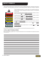
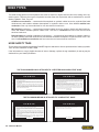
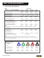
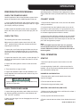
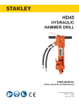
CO25
HYDRAULIC
CUT-OFF SAW
Safety, Operation and Maintenance
USER MANUAL
© 2012 Stanley Black & Decker, Inc.
New Britain, CT 06053
U.S.A.
34962 11-2013 Ver-12
DECLARATION OF CONFORMITY
DECLARATION OF CONFORMITY
ÜBEREINSTIMMUNGS-ERKLARUNG
DECLARATION DE CONFORMITE CEE
DECLARACION DE CONFORMIDAD
DICHIARAZIONE DI CONFORMITA
Hydraulic Tools
______________________________________________________________________
I, the undersigned:
Ich, der Unterzeichnende:
Je soussigné:
El abajo firmante:
lo sottoscritto:
Weisbeck, Andy
Surname and First names/Familiennname und Vornamen/Nom et prénom/Nombre y apellido/Cognome e nome
hereby declare that the equipment specified hereunder:
bestätige hiermit, daß erklaren Produkt genannten Werk oder Gerät:
déclare que l’équipement visé ci-dessous:
Por la presente declaro que el equipo se especifica a continuación:
Dichiaro che le apparecchiature specificate di seguito:
1.
Category:
Kategorie:
Catégorie:
Categoria:
Categoria:
Cut-Off-Saw, Hydraulic
2.
Make/Marke/Marque/Marca/Marca
Stanley
3.
Type/Typ/Type/Tipo/Tipo:
CO2554101, CO2514101
4.
Serial number of equipment:
Seriennummer des Geräts:
Numéro de série de l’équipement:
Numero de serie del equipo:
Matricola dell´attrezzatura:
All
Has been manufactured in conformity with
Wurde hergestellt in Übereinstimmung mit
Est fabriqué conformément
Ha sido fabricado de acuerdo con
E’ stata costruita in conformitá con
Directive/Standards
Richtlinie/Standards
Directives/Normes
Directriz/Los Normas
Direttiva/Norme
No.
Nr
Numéro
No
n.
Approved body
Prüfung durch
Organisme agréé
Aprobado
Collaudato
ISO
ISO
Machinery Directive
ISO
ISO
3744:2010
20643-A1:2012
2006/42/EC:2006
19432:2012
11148-7:2012
Self
Self
Self
Self
Self
5.
Special Provisions:
None
Spezielle Bestimmungen:
Dispositions particulières:
Provisiones especiales:
Disposizioni speciali:
6.
Representative in the Union: Patrick Vervier, Stanley Dubuis 17-19, rue Jules Berthonneau-BP 3406 41034 Blois Cedex, France.
Vertreter in der Union/Représentant dans l’union/Representante en la Union/Rappresentante presso l’Unione
Done at/Ort/Fait à/Dado en/Fatto a Stanley Hydraulic Tools, Milwaukie, Oregon USA
Signature/Unterschrift/Signature/Firma/Firma
Position/Position/Fonction/Cargo/Posizione
2 ► CO25 User Manual
Engineering Manager
Date/Datum/le/Fecha/Data
8-10-2013
TABLE OF CONTENTS
CERTIFICATE OF CONFORMITY....................................................................................................................................................2
SAFETY SYMBOLS..........................................................................................................................................................................4
SAFETY PRECAUTIONS.................................................................................................................................................................5
TOOL STICKERS & TAGS...............................................................................................................................................................7
HYDRAULIC HOSE TYPES.............................................................................................................................................................8
HOSE RECOMMENDATIONS..........................................................................................................................................................9
HTMA / EHTMA REQUIREMENTS.................................................................................................................................................10
OPERATION...................................................................................................................................................................................11
PREOPERATION PROCEDURES.................................................................................................................................................11
CONNECT HOSES.........................................................................................................................................................................11
TOOL OPERATION........................................................................................................................................................................11
STARTUP........................................................................................................................................................................................11
GENERAL OPERATION.................................................................................................................................................................12
WET CUTTING...............................................................................................................................................................................12
BROKEN CUT-OFF WHEELS........................................................................................................................................................12
SHUTDOWN...................................................................................................................................................................................12
PERIODIC MAINTENANCE...........................................................................................................................................................13
THRUST COLLAR AND INSIDE/OUTSIDE COLLAR INSPECTION.............................................................................................13
DRIVE-SHAFT SPEED CHECK.....................................................................................................................................................13
BEARING CHECK..........................................................................................................................................................................13
CARE AND STORAGE...................................................................................................................................................................13
CUTOFF WHEELS.........................................................................................................................................................................13
TOOL..............................................................................................................................................................................................13
CUTOFF WHEEL REPLACEMENT................................................................................................................................................14
COLD WEATHER OPERATION.....................................................................................................................................................14
EQUIPMENT PROTECTION & CARE............................................................................................................................................15
TROUBLESHOOTING....................................................................................................................................................................16
SPECIFICATIONS..........................................................................................................................................................................17
ACCESSORIES..............................................................................................................................................................................17
CO25 PARTS ILLUSTRATION.......................................................................................................................................................18
CO25 PARTS LIST.........................................................................................................................................................................19
IMPORTANT
To fill out a Product Warranty Recording form, and for information on your warranty,
visit Stanleyhydraulic.com and select the Warranty tab.
(NOTE: The warranty recording form must be submitted to validate the warranty).
SERVICING: This manual contains safety, operation, and routine maintenance instructions. Stanley Hydraulic Tools
recommends that servicing of hydraulic tools, other than routine maintenance, must be performed by an authorized
and certified dealer. Please read the following warning.
WARNING
SERIOUS INJURY OR DEATH COULD RESULT FROM THE IMPROPER REPAIR OR
SERVICE OF THIS TOOL.
REPAIRS AND / OR SERVICE TO THIS TOOL MUST ONLY BE DONE BY AN
AUTHORIZED AND CERTIFIED DEALER.
For the nearest authorized and certified dealer, call Stanley Hydraulic Tools at the number listed on the back of this
manual and ask for a Customer Service Representative.
CO25 User Manual ◄ 3
SAFETY SYMBOLS
Safety symbols and signal words, as shown below, are used to emphasize all operator, maintenance and repair actions which, if not strictly followed, could result in a life-threatening situation, bodily injury or damage to equipment.
This is the safety alert symbol. It is used to alert you to potential personal injury
hazards. Obey all safety messages that follow this symbol to avoid possible
injury or death.
DANGER
This safety alert and signal word indicate an imminently hazardous situation
which, if not avoided, will result in death or serious injury.
WARNING
This safety alert and signal word indicate a potentially hazardous situation
which, if not avoided, could result in death or serious injury.
CAUTION
This safety alert and signal word indicate a potentially hazardous situation
which, if not avoided, could result in death or serious injury.
CAUTION
This signal word indicates a potentially hazardous situation which, if not avoided, may result in property damage.
NOTICE
This signal word indicates a situation which, if not avoided, will result in damage
to the equipment.
IMPORTANT
This signal word indicates a situation which, if not avoided, may result in damage to the equipment.
Always observe safety symbols. They are included for your safety and for the protection of the tool.
LOCAL SAFETY REGULATIONS
Enter any local safety regulations here. Keep these instructions in an area accessible to the operator and maintenance personnel.
4 ► CO25 User Manual
SAFETY PRECAUTIONS
Tool operators and maintenance personnel must always
comply with the safety precautions given in this manual and
on the stickers and tags attached to the tool and hose.
These safety precautions are given for your safety. Review
them carefully before operating the tool and before performing general maintenance or repairs.
Supervising personnel should develop additional precautions relating to the specific work area and local safety
regulations. If so, place the added precautions in the
space provided on the previous page.
The CO25 Hydraulic Cut-Off Saw will provide safe and
dependable service if operated in accordance with the
instructions given in this manual. Read and understand
this manual and any stickers and tags attached to the tool
and hose before operation. Failure to do so could result in
personal injury or equipment damage.
• Do not operate a damaged, improperly adjusted, or
incompletely assembled tools.
• Never wear loose clothing that can get entangled in the
working parts of the tool.
• Keep all parts of your body away from the rotating
parts. Long hair or loose clothing can become drawn into
rotating components.
• Always use accessories that conform to the specifications given in this manual.
• Release the trigger if the power supply has been interrupted.
• When working near electrical conductors, always assume that all conductors are energized and that insulation, clothing and hoses can conduct electricity. Use hose
labeled and certified as non-conductive.
• To avoid personal injury or equipment damage, all tool
repair, maintenance and service must only be performed
by authorized and properly trained personnel.
• The operator must start in a work area without bystanders. Flying debris can cause serious injury.
• Do not operate the tool unless thoroughly trained or under
the supervision of an instructor. Establish a training program for all operators to ensure safe operation.
• Always wear safety equipment such as goggles, ear,
breathing and head protection, and safety shoes at all
times when operating the tool. Use gloves and aprons
when necessary.
Warning: Use of this tool on certain materials during
demolition could generate dust potentially containing
a variety of hazardous substances such as asbestos,
silica or lead. Inhalation of dust containing these or other
hazardous substances could result in serious injury,
cancer or death. Protect yourself and those around you.
Research and understand the materials you are cutting. Follow correct safety procedures and comply with
all applicable national, state or provisional health and
safety regulations relating to them, including, if appropriate arranging for the safe disposal of the materials by a
qualified person.
• The operator must be familiar with all prohibited work
areas such as excessive slopes and dangerous terrain
conditions.
• Maintain proper footing and balance at all times. Alway
hold the tool with both hands when the unit is running. Use
a firm grip.
• Do not inspect or clean the tool while the hydraulic power
source is connected. Accidental engagement of the tool
can cause serious injury.
• Always connect hoses to the tool hose couplers before
energizing the hydraulic power source. Be sure all hose
connections are tight and are in good condition.
• Do not operate the tool at oil temperatures above
140°F/60°C. Operation at higher temperatures can cause
higher than normal temperatures at the tool which can
result in operator discomfort.
CO25 User Manual ◄ 5
SAFETY PRECAUTIONS
• Never carry the tool or put it down while the wheel is
rotating. Make sure it is completely stopped before moving
your position or set the tool down.
• Do not operate the tool with the wheel guard removed.
• Keep the handles dry, clean and free of oil at all times.
• Operate the tool in well ventilated areas only.
• Do not operate the tool if the wheel does not stop when
the trigger is released.
• Inspect the wheel guard and collars for damage after any
wheel breakage on the tool.
• Always use full throttle when cutting.
mounted on the saw.
• If the cut-off saw is dropped with a cutting wheel installed, thoroughly examine the cutting wheel before use.
• Make sure the cutting wheel is correctly mounted and
tightened before use.
• Operate the cut-off saw at no load for 30 seconds in a
safe position. If considerable vibration or other defects
are detected, stop operation of the tool immediately and
determine the cause. Do not use the tool until the defect
is corrected.
• Only use cutting wheels that comply with ANSI B7.5/
ISO 525, 603.
• Never cock, jam or wedge the wheel during the cut. Do
not use the side of the wheel as a cutting surface and be
aware of kick-back from the saw.
• Check that the maximum operating speed of the cutting
wheel is equal to or greater than the rated shaft speed
of the cut-off saw. Wheels must be rated at 4700 rpm
minimum.
• Make sure the tool is designed for the wheel direction
suitable for the job. Do not reverse the direction of the
wheel rotation by changing the direction of the oil flow.
• Warning: Hydraulic fluid under pressure could cause
skin injection injury. If you are injured by hydraulic
fluid, get medical attention immediately
• Always operate the tool within its rated capacity. Never
exceed the maximum operating speed marked on the
wheel.
• Always support and secure items being worked on.
• Do not operate the tool near flammable materials, sparks
can ignite flammable or combustible materials.
• Do not over-reach.
• Do not use the tool for applications for which it was not
designed.
• Keep the wheel off all surfaces when starting the saw.
• Do not attempt to adjust the flow control on the valve
handle.
• Know the location of buried or covered services before
starting work.
• Adjust the wheel guard so it is between you and the cutting wheel.
• Never operate the tool when you are tired.
CUT-OFF WHEEL SAFETY
• Always inspect the cut-off wheels for possible damage before operating the tool. Do not use a wheel that is cracked
or otherwise damaged.
• Never transport or store the tool with the cut-off wheel
6 ► CO25 User Manual
• Caution when handling the work piece after cutting,
object can be hot and have sharp edges, use your personal protection equipment.
• Keep your work area clean and clear of tripping hazards, oily surfaces and hoses laying about can be hazardous.
• Make sure adequate lighting is always available.
• Never operate the tool if you cannot be sure that
underground utilities are not present. Underground
electrical utilities present an electrocution hazard.
Underground gas utilities present an explosion hazard.
Other underground utilities may present other hazards.
• Do not operate this tool in a potentially explosive environment. Do not grind on vessels containing combustible
substances.
• Any use of this tool outside those stated in this manual
are forbidden.
TOOL STICKERS & TAGS
D
Stanley Hydraulic tools
30 LPM @ 138 B AR
EHTMA CATEGORY
Division of the Stanley Works
3810 SE Naef Road
Milwaukie, OR 97267
11207
CIRCUIT TYPE D DECAL
(CE MODELS ONLY)
05152
ADDRESS DECAL
33206
CO25 NAME TAG
28322
CE DECAL
(CE MODELS ONLY)
Lwa
113
03786
GPM DECAL
28811
INFORMATION PLAQUE
05153
ADDRESS DECAL
(CE MODELS ONLY)
52539
SOUND POWER DECAL
(CE MODELS ONLY)
CAUTION
PROTECT YOUR EYES...
WEAR SAFETY GOGGLES
28886
COMPOSITE DECAL
(CE MODELS ONLY)
1. DO NOT USE DAMAGED WHEELS.
2. USE FULL TROTTLE ONLY WHILE CUTTING.
3. USE ONLY WHEELS MARKED HIGH SPEED REINFORCED THAT MEET
REQUIREMENTS OF ANSI B7.1,B7.5 WHEELS SHOULD BE NO LARGER THAN
14" DIA X 5/32" THICK WITH A 1" ARBOR HOLE & RATED FOR 5300 RPM
MINIMUM SPEED.
4. INSPECT WHEEL GUARD & COLLARS FOR DAMAGE AFTER ANY WHEEL
BREAKAGE ON THE MACHINE.
5. MAXIMUM SPINDLE SPEED IS 5300 RPM.
6. READ OPERATION MANUAL.
05868 SAFETY LABEL
NOTE
THE INFORMATION LISTED ON
THE STICKERS SHOWN, MUST BE
LEGIBLE AT ALL TIMES.
REPLACE DECALS IF THEY
BECOME WORN OR DAMAGED.
REPLACEMENTS ARE AVAILABLE
FROM YOUR LOCAL STANLEY
DISTRIBUTOR.
The safety tag (P/N 15875) at right is attached to
the tool when shipped from the factory. Read and
understand the safety instructions listed on this tag
before removal. We suggest you retain this tag and
attach it to the tool when not in use.
D A N G E R
1.
FAILURE TO USE HYDRAULIC HOSE LABELED AND CERTIFIED AS NON-CONDUCTIVE WHEN USING HYDRAULIC
TOOLS ON OR NEAR ELECTRICAL LINES MAY RESULT IN
DEATH OR SERIOUS INJURY.
BEFORE USING HOSE LABELED AND CERTIFIED AS NONCONDUCTIVE ON OR NEAR ELECTRIC LINES BE SURE THE
HOSE IS MAINTAINED AS NON-CONDUCTIVE. THE HOSE
SHOULD BE REGULARLY TESTED FOR ELECTRIC CURRENT LEAKAGE IN ACCORDANCE WITH YOUR SAFETY
DEPARTMENT INSTRUCTIONS.
2.
A HYDRAULIC LEAK OR BURST MAY CAUSE OIL INJECTION INTO THE BODY OR CAUSE OTHER SEVERE
PERSONAL INJURY.
A.
DO NOT EXCEED SPECIFIED FLOW AND PRESSURE
FOR THIS TOOL. EXCESS FLOW OR PRESSURE MAY
CAUSE A LEAK OR BURST.
B.
DO NOT EXCEED RATED WORKING PRESSURE OF
HYDRAULIC HOSE USED WITH THIS TOOL. EXCESS
PRESSURE MAY CAUSE A LEAK OR BURST.
C. CHECK TOOL HOSE COUPLERS AND CONNECTORS
DAILY FOR LEAKS. DO NOT FEEL FOR LEAKS WITH
YOUR HANDS. CONTACT WITH A LEAK MAY RESULT
IN SEVERE PERSONAL INJURY.
D A N G E R
D. DO NOT LIFT OR CARRY TOOL BY THE HOSES. DO
NOT ABUSE HOSE. DO NOT USE KINKED, TORN OR
DAMAGED HOSE.
3.
MAKE SURE HYDRAULIC HOSES ARE PROPERLY CONNECTED TO THE TOOL BEFORE PRESSURING SYSTEM.
SYSTEM PRESSURE HOSE MUST ALWAYS BE CONNECTED TO TOOL “IN” PORT. SYSTEM RETURN HOSE
MUST ALWAYS BE CONNECTED TO TOOL “OUT” PORT.
REVERSING CONNECTIONS MAY CAUSE REVERSE
TOOL OPERATION WHICH CAN RESULT IN SEVERE
PERSONAL INJURY.
4.
DO NOT CONNECT OPEN-CENTER TOOLS TO CLOSEDCENTER HYDRAULIC SYSTEMS. THIS MAY RESULT IN
LOSS OF OTHER HYDRAULIC FUNCTIONS POWERED BY
THE SAME SYSTEM AND/OR SEVERE PERSONAL INJURY.
5.
BYSTANDERS MAY BE INJURED IN YOUR WORK AREA.
KEEP BYSTANDERS CLEAR OF YOUR WORK AREA.
6.
WEAR HEARING, EYE, FOOT, HAND AND HEAD PROTECTION.
7.
TO AVOID PERSONAL INJURY OR EQUIPMENT DAMAGE,
ALL TOOL REPAIR MAINTENANCE AND SERVICE MUST
ONLY BE PERFORMED BY AUTHORIZED AND PROPERLY
TRAINED PERSONNEL.
I M P O R T A N T
I M P O R T A N T
READ OPERATION MANUAL AND
SAFETY INSTRUCTIONS FOR THIS
TOOL BEFORE USING IT.
READ OPERATION MANUAL AND
SAFETY INSTRUCTIONS FOR THIS
TOOL BEFORE USING IT.
USE ONLY PARTS AND REPAIR
PROCEDURES APPROVED BY
STANLEY AND DESCRIBED IN THE
OPERATION MANUAL.
USE ONLY PARTS AND REPAIR
PROCEDURES APPROVED BY
STANLEY AND DESCRIBED IN THE
OPERATION MANUAL.
TAG TO BE REMOVED ONLY BY
TOOL OPERATOR.
TAG TO BE REMOVED ONLY BY
TOOL OPERATOR.
SEE OTHER SIDE
SEE OTHER SIDE
SAFETY TAG P/N 15875 (Shown smaller then actual size)
CO25 User Manual ◄ 7
HOSE TYPES
The rated working pressure of the hydraulic hose must be equal to or higher than the relief valve setting on the hydraulic system. There are three types of hydraulic hose that meet this requirement and are authorized for use with
Stanley Hydraulic Tools. They are:
Certified non-conductive — constructed of thermoplastic or synthetic rubber inner tube, synthetic fiber braid
reinforcement, and weather resistant thermoplastic or synthetic rubber cover. Hose labeled certified nonconductive is the only hose authorized for use near electrical conductors.
Wire-braided (conductive) — constructed of synthetic rubber inner tube, single or double wire braid reinforcement, and weather resistant synthetic rubber cover. This hose is conductive and must never be used near
electrical conductors.
Fabric-braided (not certified or labeled non-conductive) — constructed of thermoplastic or synthetic rubber inner tube, synthetic fiber braid reinforcement, and weather resistant thermoplastic or synthetic rubber cover. This
hose is not certified non-conductive and must never be used near electrical conductors.
HOSE SAFETY TAGS
To help ensure your safety, the following DANGER tags are attached to all hose purchased from Stanley Hydraulic
Tools. DO NOT REMOVE THESE TAGS.
If the information on a tag is illegible because of wear or damage, replace the tag immediately. A new tag may be
obtained from your Stanley Distributor.
D A N G E R
D A N G E R
1.
FAILURE TO USE HYDRAULIC HOSE LABELED AND CERTIFIED AS NON-CONDUCTIVE
WHEN USING HYDRAULIC TOOLS ON OR NEAR ELECTRIC LINES MAY RESULT IN
DEATH OR SERIOUS INJURY.
FOR PROPER AND SAFE OPERATION MAKE SURE THAT YOU HAVE BEEN PROPERLY TRAINED IN CORRECT PROCEDURES REQUIRED FOR WORK ON OR AROUND
ELECTRIC LINES.
2.
BEFORE USING HYDRAULIC HOSE LABELED AND CERTIFIED AS NON-CONDUCTIVE
ON OR NEAR ELECTRIC LINES. WIPE THE ENTIRE LENGTH OF THE HOSE AND FITTING WITH A CLEAN DRY ABSORBENT CLOTH TO REMOVE DIRT AND MOISTURE AND
TEST HOSE FOR MAXIMUM ALLOWABLE CURRENT LEAKAGE IN ACCORDANCE WITH
SAFETY DEPARTMENT INSTRUCTIONS.
3.
DO NOT EXCEED HOSE WORKING PRESSURE OR ABUSE HOSE. IMPROPER USE
OR HANDLING OF HOSE COULD RESULT IN BURST OR OTHER HOSE FAILURE.
KEEP HOSE AS FAR AWAY AS POSSIBLE FROM BODY AND DO NOT PERMIT DIRECT
CONTACT DURING USE. CONTACT AT THE BURST CAN CAUSE BODILY INJECTION
AND SEVERE PERSONAL INJURY.
4.
HANDLE AND ROUTE HOSE CAREFULLY TO AVOID KINKING, ABRASION, CUTTING, OR
CONTACT WITH HIGH TEMPERATURE SURFACES. DO NOT USE IF KINKED. DO NOT
USE HOSE TO PULL OR LIFT TOOLS, POWER UNITS, ETC.
5.
CHECK ENTIRE HOSE FOR CUTS CRACKS LEAKS ABRASIONS, BULGES, OR DAMAGE TO COUPLINGS IF ANY OF THESE CONDITIONS EXIST, REPLACE THE HOSE
IMMEDIATELY. NEVER USE TAPE OR ANY DEVICE TO ATTEMPT TO MEND THE HOSE.
6.
AFTER EACH USE STORE IN A CLEAN DRY AREA.
SEE OTHER SIDE
SIDE 1
SEE OTHER SIDE
(Shown smaller than actual size)
DO NOT REMOVE THIS TAG
DO NOT REMOVE THIS TAG
THE TAG SHOWN BELOW IS ATTACHED TO “CERTIFIED NON-CONDUCTIVE” HOSE
SIDE 2
D A N G E R
D A N G E R
1.
DO NOT USE THIS HYDRAULIC HOSE ON OR NEAR ELECTRIC LINES. THIS HOSE IS
NOT LABELED OR CERTIFIED AS NON-CONDUCTIVE. USING THIS HOSE ON OR NEAR
ELECTRICAL LINES MAY RESULT IN DEATH OR SERIOUS INJURY.
5.
CHECK ENTIRE HOSE FOR CUTS CRACKS LEAKS ABRASIONS, BULGES, OR DAMAGE TO
COUPLINGS IF ANY OF THESE CONDITIONS EXIST, REPLACE THE HOSE IMMEDIATELY.
NEVER USE TAPE OR ANY DEVICE TO ATTEMPT TO MEND THE HOSE.
2.
FOR PROPER AND SAFE OPERATION MAKE SURE THAT YOU HAVE BEEN PROPERLY
TRAINED IN CORRECT PROCEDURES REQUIRED FOR WORK ON OR AROUND ELECTRIC LINES.
6.
AFTER EACH USE STORE IN A CLEAN DRY AREA.
3.
DO NOT EXCEED HOSE WORKING PRESSURE OR ABUSE HOSE. IMPROPER USE OR
HANDLING OF HOSE COULD RESULT IN BURST OR OTHER HOSE FAILURE. KEEP HOSE
AS FAR AWAY AS POSSIBLE FROM BODY AND DO NOT PERMIT DIRECT CONTACT
DURING USE. CONTACT AT THE BURST CAN CAUSE BODILY INJECTION AND SEVERE
PERSONAL INJURY.
4.
HANDLE AND ROUTE HOSE CAREFULLY TO AVOID KINKING, CUTTING, OR CONTACT
WITH HIGH TEMPERATURE SURFACES. DO NOT USE IF KINKED. DO NOT USE HOSE TO
PULL OR LIFT TOOLS, POWER UNITS, ETC.
SEE OTHER SIDE
SEE OTHER SIDE
SIDE 1
SIDE 2
(Shown smaller than actual size)
8 ► CO25 User Manual
DO NOT REMOVE THIS TAG
DO NOT REMOVE THIS TAG
THE TAG SHOWN BELOW IS ATTACHED TO “CONDUCTIVE” HOSE.
All hydraulic hose must meet or exceed
specifications as set forth by SAE J517.
All hydraulic hose must have at least a rated
minimum working pressure equal to the maximum hydraulic system relief valve setting.
This chart is intended to be used for hydraulic
tool applications only based on Stanley Hydraulic Tools tool operating requirements and
should not be used for any other applications.
The chart to the right shows recommended
minimum hose diameters for various hose
lengths based on gallons per minute (gpm)/
liters per minute (lpm). These recommendations are intended to keep return line pressure
(back pressure) to a minimum acceptable level to ensure maximum tool performance.
Tool to Hydraulic Circuit Hose
Recommendations
15-34
MM
Inside Diameter
INCH
USE
(Press/Return)
PSI
up to 10
up to 3
3/8
10
Both
2250
49-60
13-16
FLOW >>>
RETURN
<<< FLOW
PRESSURE
26-100
up to 25
100-200
51-100
up to 50
100-300
51-100
up to 50
26-100
up to 25
8-30
up to 8
30-60
15-30
up to 15
30-90
15-30
up to 15
7.5-30
up to 7.5
Figure 1. Typical Hose Connections
49-60
38-49
10-13
13-16
19-40
5-10.5
38-49
19-40
5-10.5
10-13
19-40
5-10.5
38-49
15-23
10-13
15-23
4-6
19
25.4
16
19
19
25.4
5/8
3/4
3/4
1
19
3/4
1
16
3/4
16
19
3/4
5/8
16
5/8
5/8
16
13
13
10
5/8
1/2
1/2
3/8
Return
Pressure
Return
Pressure
Return
Pressure
Return
Pressure
Both
Return
Pressure
Both
Both
Both
Both
2500
2500
2500
2500
2500
2500
2500
2500
2500
2500
2500
2500
2500
2500
2500
175
175
175
175
175
175
175
175
175
175
175
175
175
175
175
155
BAR
Min. Working Pressure
Certified Non-Conductive Hose - Fiber Braid - for Utility Bucket Trucks
METERS
Hose Lengths
FEET
Conductive Hose - Wire Braid or Fiber Braid -DO NOT USE NEAR ELECTRICAL CONDUCTORS
4-6
4-9
LPM
Oil Flow
GPM
HOSE RECOMMENDATIONS
CO25 User Manual ◄ 9
HTMA / EHTMA REQUIREMENTS
HTMA / EHTMA REQUIREMENTS
HTMA
HYDRAULIC SYSTEM REQUIREMENTS
TYPE I
Nominal Operating Pressure
(at the power supply outlet)
4-6 gpm
(15-23 lpm)
1500 psi
(103 bar)
TOOL TYPE
TYPE II
TYPE RR
7-9 gpm
(26-34 lpm)
1500 psi
(103 bar)
9-10.5 gpm
(34-40 lpm)
1500 psi
(103 bar)
System relief valve setting
(at the power supply outlet)
2100-2250 psi
(145-155 bar)
2100-2250 psi
(145-155 bar)
2200-2300 psi
(152-159 bar)
2100-2250 psi
(145-155 bar)
Maximum back pressure
(at tool end of the return hose)
250 psi
(17 bar)
250 psi
(17 bar)
250 psi
(17 bar)
250 psi
(17 bar)
Measured at a max. fluid viscosity of:
(at min. operating temperature)
400 ssu*
400 ssu*
400 ssu*
400 ssu*
(82 centistokes) (82 centistokes) (82 centistokes) (82 centistokes)
Temperature: Sufficient heat rejection
capacity to limit max. fluid temperature to:
(at max. expected ambient temperature)
140° F
(60° C)
Flow Range
140° F
(60° C)
140° F
(60° C)
TYPE III
11-13 gpm
(42-49 lpm)
1500 psi
(103 bar)
140° F
(60° C)
3 hp
5 hp
6 hp
7 hp
Min. cooling capacity at a temperature
(2.24 kW)
(3.73 kW)
(5.22 kW)
(4.47 kW)
difference of between ambient and fluid
40° F
40° F
40° F
40° F
temps
(22° C)
(22° C)
(22° C)
(22° C)
NOTE:
Do not operate the tool at oil temperatures above 140° F (60° C). Operation at higher temperatures can cause operator
discomfort at the tool.
Filter
Min. full-flow filtration
Sized for flow of at least:
(For cold temp. startup and max.
dirt-holding capacity)
25 microns
30 gpm
(114 lpm)
Hydraulic fluid Petroleum based
(premium grade, anti-wear, non-conductive)
Viscosity (at min. and max. operating temps)
100-400 ssu*
25 microns
30 gpm
(114 lpm)
25 microns
30 gpm
(114 lpm)
100-400 ssu*
100-400 ssu*
(20-82 centistokes)
25 microns
30 gpm
(114 lpm)
100-400 ssu*
NOTE:
When choosing hydraulic fluid, the expected oil temperature extremes that will be experienced in service determine the
most suitable temperature viscosity characteristics. Hydraulic fluids with a viscosity index over 140 will meet the requirements
over a wide range of operating temperatures.
*SSU = Saybolt Seconds Universal
EHTMA
HYDRAULIC SYSTEM
REQUIREMENTS
CLASSIFICATION
B
C
D
Nominal Operating Pressure
(at the power supply outlet)
3.5-4.3 gpm
(13.5-16.5 lpm)
1870 psi
(129 bar)
4.7-5.8 gpm
(18-22 lpm)
1500 psi
(103 bar)
7.1-8.7 gpm
(27-33 lpm)
1500 psi
(103 bar)
9.5-11.6 gpm
(36-44 lpm)
1500 psi
(103 bar)
11.8-14.5 gpm
(45-55 lpm)
1500 psi
(103 bar)
System relief valve setting
(at the power supply outlet)
2495 psi
(172 bar)
2000 psi
(138 bar)
2000 psi
(138 bar)
2000 psi
(138 bar)
2000 psi
(138 bar)
Flow Range
NOTE: These are general hydraulic system requirements. See tool specification page for tool specific requirements
10 ► CO25 User Manual
OPERATION
PREOPERATION PROCEDURES
CHECK THE POWER SOURCE
3. Check that the safety catch on the handle assembly is
operating properly. It should prevent engagement of the
trigger unless the catch is pressed down fully in the handle
slot.
Careful inspection of the tool and hydraulic system before
startup is important for safe, reliable operation of the tool.
CONNECT HOSES
1. Using a calibrated flowmeter and pressure gauge, check
that the hydraulic power source develops a flow of 7–9 gpm
(26–34 lpm) at 2000 psi (140 bar).
1. Wipe all hose couplers with a clean, lint-free cloth before
making connections.
2. Make certain the hydraulic power source is equipped
with a relief valve set to open at 2100–2250 psi (145–155
bar).
2. Connect hoses from the hydraulic power source to the
tool fittings or quick disconnects. It is good practice to connect the return hose first and disconnect it last to minimize
or eliminate trapped pressure within the wrench.
CHECK THE TOOL
The following items should be checked daily.
Make sure the hydraulic system control valve is in the
“OFF” position and the hoses are disconnected before
inspecting the cutoff saw.
1. Inspect the cut-off wheel and guard. Make sure the correct cut-off wheel is installed for the job. If not, follow the
instructions for Cut-off Wheel Replacement section of this
manual.
2. Inspect the wheel for chips, cracks, or other damage. For
maximum tool performance, replace the wheel if it is worn
or defective.
3. Inspect the wheel guard for cracks or other structural
damage.
3. Observe the flow indicators stamped on the valve handle
assembly and the hose couplers to ensure that the flow is
in the proper directions. The female couple on the tools “IN”
port is the inlet (pressure) coupler.
Note:
If the uncoupled hoses are left in the sun, pressure
increase within the hoses can make them difficult to
connect. Whenever possible, connect the free ends of
hoses together.
TOOL OPERATION
STARTUP
1. Move the hydraulic system control valve to the “ON”
position.
4. There should be no signs of leaks.
2. At the beginning of each shift, or after a new wheel is
installed, run the cut-off saw at operating speed for at least
one minute before starting work.
5. Inspect the handlebar. Make sure the handlebar is securely fastened to the cutoff saw and is clean of any oil to
ensure a firm grip.
HANDHELD CONFIGURATION:
IMPORTANT
Check the speed of the motor output shaft after every
100 hours of operation.
CHECK TRIGGER MECHANISM
1. Inspect the trigger and safety catch. Make sure the trigger operates smoothly and is free to travel between the
“ON: and “OFF” positions.
2. Make sure the trigger is set to disengage the cut-off saw
when released.
1.Press the safety catch into the handle, then slowly
squeeze the trigger.
2. Run the saw at least one minute.
3. Release the trigger and safety catch.
MOUNTED CONFIGURATION (SAW CART):
1. Make sure the lower edge of the cutoff wheel is at least 1
inch above the work surface.
2. Slowly squeeze the hand control lever.
3. Run the saw at least one minute, then release the control
lever.
CO25 User Manual ◄ 11
OPERATION
If excessive vibration or any other defect is detected, stop
the tool immediately and determine the cause. Do not use
the tool until the problem is corrected.
GENERAL OPERATION
HANDHELD CONFIGURATION:
1. Whenever possible, clamp or hold down the work and
support it securely on both sides of the cut.
2. Press the safety catch into the handle, then slowly
squeeze the trigger.
3. Start the cut with the wheel rotating. Start the work gently
with consistent pressure. Do not bump the saw into the
workpiece.
4. Feed the wheel through the material as fast as possible
without slowing the wheel rotation speed.
Cutting through the material too slowly causes heat expansion and can result in wheel “pinching” in the material. This
is one of the most common causes or wheel breakage.
MOUNTED CONFIGURATION (SAW CART):
When the cutoff saw is mounted on a saw cart, always use
a motor-type hydraulic system control valve to turn the saw
“ON” and “OFF”. All ports must be connected to the tank
(hydraulic system reservoir) when the control valve is in
neutral. Alternatively, use a direct line from the tool outlet to
the tank.
IMPORTANT
Keep all four wheels of the cart on the cutting surface
at all times. Do not tip the front of the cart up during
operation or while the blade is in motion.
1. Align the cut line indicator on the line to be cut.
2. Lower the blade to approximately 1/2 to 1-inch above the
cutting surface. Set the depth gauge to ensure accurate
cutting depth.
3. Make sure the water hose and its connections are secure and there is a steady flow of coolant water.
4. Slowly squeeze the hand control lever.
5. Slowly and safely lower the rotating blade into the cutting
surface to the desired depth:
Increase the depth by turning the depth-control crank counterclockwise (CCW).
12 ► CO25 User Manual
Periodically look at the depth gauge and pointer to check
the actual depth of the cutting blade.
6. Move slowly and safely forward along the cutting line
until the desired cut is complete. The safe forward rate
depends on your blade type.
7. Release the hand control lever.
8. To raise the blade from of the cutting surface, wait until
the blade comes to a complete stop in the work material.
Turn the depth-control crank clockwise (CW) until the blade
clears the surface.
WET CUTTING
1. Make sure the cutting wheel is suitable for wet cutting.
2. When shutting down a wet-cutting operation:
a. Stop the tool.
b. Shut off the water.
Restart the tool and allow the wheel to spin off the excess
water.
BROKEN CUT-OFF WHEELS
Cut-off wheels designed for use with portable saws are
extremely tough. When used as directed, they are difficult
to break during normal use.
If a wheel breaks while operating the cut-off saw, investigate the cause of the failure and correct the problem as
soon as possible. If you cannot determine the cause of
failure, contact the wheel manufacturer.
SHUTDOWN
1. Move the hydraulic system control valve to the “OFF”
position.
2. Disconnect the hydraulic hoses from the tool (first the
input (supply) hose, then the output (return) hose).
3. Place dust plugs in the hose ends, couplers or tool ports,
as applicable.
4. Wipe the tool thoroughly with a clean dry cloth.
5. Clean any foreign matter from the cut-off wheel surfaces.
OPERATION
PERIODIC MAINTENANCE
CARE AND STORAGE
For maximum performance and reliability of the tool, periodically check the following components.
Remove the cutoff wheel from the tool after use. Do not
store or transport the saw with the wheel installed. Clean
and inspect the wheel and tool before storing.
THRUST COLLAR AND INSIDE/OUTSIDE
COLLAR INSPECTION
CUTOFF WHEELS
Periodically inspect the thrust collar for damage when you
remove the cut-off wheel (refer to Cutoff Wheel Replacement).
1. Remove the key and thrust collar from the motor shaft.
2. Check the thrust collar for burrs. Remove burrs as required.
3. Check the threads on the clamping setscrew.
4. Inspect the collar bores and flanges.
5. Check for burrs. Remove burrs as required.
6. Check that the bearing surfaces are flat and run true
when mounted on the motor shaft and thrust collar.
All abrasive cutoff wheels are breakable. Exercise care in
handling and storage to prevent damage.
1. Clean used wheels to remove any dirt, debris, or grease.
Dry thoroughly.
2. Inspect the wheel for chips, cracks, or other damage. For
maximum tool performance, replace the wheel if it is worn
or defective.
3. Store cutoff wheels on a flat surface of steel or similar
rigid material.
4. If wheels are supplied with blotters attached, insert suitable separators between each wheel and the supporting
surface to preserve flatness.
DRIVE-SHAFT SPEED CHECK
5. Do not store wheels where they will be exposed to high
humidity, water or other liquids, excessive heat, or freezing
temperatures.
Check the speed of the motor output shaft at least every
100 hours of operation. The test should be performed only
by a trained, experienced technician.
6. Avoid temperatures low enough to cause condensation
on the wheels if they are moved from storage to an area of
higher temperature.
• Maintain a record of the speed checks.
7. Wheels carried on emergency vehicles should be removed after use, and discarded or stored carefully (steps 1
and 2).
• The maximum rated speed of the CO25 Hydraulic Cutoff
Saw is 4500 rpm.
• The rated speed of the cutting wheel must be equal to,
or greater than that of the tool to ensure the integrity of the
wheel at maximum tool speed.
• Use the hydraulic power supply normally used with the
cutoff saw when conducting this test.
• Excessive speed may be caused by excessive hydraulic
fluid flow to the tool.
BEARING CHECK
TOOL
1. Clean the tool to remove any dirt, debris, or grease. Dry
with compressed air or clean dry cloths.
2. Replace any damaged or missing safety labels and tags
before storing the tool. Otherwise, the tool might be improperly used by someone who is not familiar with the safety
requirements.
3. Store the tool in a clean, dry place.
Periodically inspect the bearings and associated parts for
proper operation. A worn or damaged bearing can cause
motor damage.
CO25 User Manual ◄ 13
OPERATION
CUTOFF WHEEL REPLACEMENT
1. Move the hydraulic system control valve to the Off position.
2. Disconnect the hydraulic hoses from the tool (first the
input (supply) hose, then the output (return) hose).
3. Install the inside collar and blotter, rotate the collar to
align the slot in the collar with the pin on the thrust collar.
4. The maximum rated speed of the hydraulic cutoff saw
is 4500 rpm. Never install a cutoff wheel that is not rated
equal to or greater than that of the tool to ensure the integrity of the wheel at the maximum tool speed.
5. Prior to installing the wheel, inspect it for chips, cracks or
other damage and replace if damaged.
6. Install the outside blotter and collar, rotate the collar so
that the flat on the motor shaft aligns with the flat on the
outside collar.
7. Install the wheel nut using a wrench while gripping the
cutoff wheel. Tighten securely.
COLD WEATHER OPERATION
Before using the tool in cold weather, preheat the hydraulic
fluid with the power unit operating at a low speed. The oil
should be at or above 50°F (10°C) with a viscosity of 400
SSU (82 cs) before operating the tool.
14 ► CO25 User Manual
TOOL PROTECTION & CARE
NOTICE
In addition to the Safety Precautions found in
this manual, observe the following for equipment
protection and care.
• Make sure all couplers are wiped clean before connection.
• The hydraulic circuit control valve must be in the “OFF” position when coupling or uncoupling
hydraulic tools. Failure to do so may result in damage to the quick couplers and cause overheating
of the hydraulic system.
• Always store the tool in a clean dry space, safe from damage or pilferage.
• Make sure the circuit PRESSURE hose (with male quick disconnect) is connected to the “IN” port.
The circuit RETURN hose (with female quick disconnect) is connected to the opposite port. Do not
reverse circuit flow. This can cause damage to internal seals.
• Always replace hoses, couplings and other parts with replacement parts recommended by Stanley
Hydraulic Tools. Supply hoses must have a minimum working pressure rating of 2500 psi/172 bar.
• Do not exceed the rated flow (see Specifications) in this manual for correct flow rate and
model number. Personal Injury and rapid failure of the internal seals may result.
• Always keep critical tool markings, such as warning stickers and tags legible.
• Tool repair should be performed by experienced personnel only.
• Make certain that the recommended relief valves are installed in the pressure side of the system.
• Do not use the tool for applications for which it was not intended.
CO25 User Manual ◄ 15
TROUBLESHOOTING
If symptoms of poor performance develop, the following chart can be used as a guide to correct the problem. When diagnosing faults in operation of the wrench, always check that the hydraulic power source is supplying the correct hydraulic
flow and pressure to the tool as listed in the following table. Use a flow meter known to be accurate. Check the flow with
the hydraulic fluid temperature at least 80o F/27o C.
PROBLEM
Tool does not operate.
Tool operates in reverse.
Oil leakage between motor housing
and ON/OFF vlave block or motor.
Trigger difficult to operate.
Saw cuts too slowly.
16 ► CO25 User Manual
CAUSE
SOLUTION
Hydraulic ontrol valve OFF.
Turn the hydraulic system control
valve ON.
Hydraulic hoses not connected properly.
Make sure the hoses are connected
and the couplers are tight.
Hydraulic system not functioning.
Check power unit for correct flow and
presssure.
Couplers or hoses blocked.
Remove obstruction.
Mechanical failure.
Disassemble tool and inspect for damage.
Hoses connected to wrong ports on
tool.
Connect input (supply) line to IN port
and connect output (return) line to
OUT port.
Oil tube o-ring failure.
Replace o-ring.
Motor face seal failure.
Replace seal.
Hoses connected to wrong ports on
tool.
Connect input (supply) line to IN port
and connect output (return) line to
OUT port.
Excessive back-pressure.
If back pressure is greater than 250
psi/17 bar, correct the return line obstruction or restriction.
Wrong cut-off wheel for work material.
Use correct wheel.
Insufficient oil flow.
Adjust oil flow to 7-9 gpm/26-34 lpm.
Relief valve setting too low.
Adjust relief valve to 2100-2250
psi/145-155 bar.
SPECIFICATIONS
Wheel Capacity..............................................................................................................................................14-inch/15.6 cm
Weight.................................................................................................................................................................... 20 lbs/9 kg
Overall Length...................................................................................................................................................21-inch/53 cm
Width................................................................................................................................................................. 11-inch/28 cm
Pressure Range........................................................................................................................... 1500-2000 psi/105-140 bar
Flow Range............................................................................................................................................... 7-9 gpm/26-34 lpm
Optimum Flow....................................................................................................................................................8 gpm/30 lpm
System Type................................................................................................................................ Open Center, HTMA Type II
Porting...............................................................................................................................................................8 SAE O-Ring
Connect Size and Type................................................................................................................ 3/8-inch Male Pipe Adapter
Max Spindle Speed.................................................................................................................................................. 4700 rpm
ACCESSORIES
DESCRIPTION
PART NUMBER
14-inch Abrasive Wheel for Metal, 1-inch Arbor............................................................................................................ 02691
14-inch Abrasive Wheel for Masonry, 1-inch Arbor........................................................................................................ 02692
Diamond Blade, 14-inch Dry Cut................................................................................................................................... 62358
Water Attachment Kit for CO25 (Includes (1) Water Hose Assy P/N-33220, (1) 9.125-inch Long Tube P/N-33226, (1)7.812-inch Long Tube P/N-33227, (1) Brass Adaptor P/N-35196, (3) Male 90Deg Elbow 1/4” hose barb P/N-33223, (1)
Male Elbow Brass P/N-35197....................................................................................................................................... 33228
Slab Saw Cart............................................................................................................................................................... 69290
Water Tank Kit for Slab Saw Cart (Includes (1) Tank Top Bracket P/N-69296, (1) Tank Bracket P/N-69542, (1) Water tank
P/N-41240, (1) Needle Valve Clamp P/N-69914, (2) Capscrews P/N-32412, (9) Capscrews P/N-15476, and (11) Nuts P/N00719............................................................................................................................................................................ 69704
Handle Extension Kit (Includes- (2) Oil Tubes P/N-31945, (1) Handle Weldment P/N-34116, (1) Extension P/N-34172, (4)
O-Rings P/N-00175, Hardware- (2) Lockwashers P/N-01459, (2) 3/8” Capscrews P/N-02116, (4) 5/16” Capscrews P/N10888 and Inst Sheet ................................................................................................................................................... 34175
SOUND POWER AND VIBRATION DECLARATION
Test conducted on CO25541, S/N 673 operated at standard 12 gpm input.....................................................................................
Measured A-weighted sound power level, Lwa (ref. 1pW) in decibels............................................................................ 109.4 dBA
Uncertainty, Kwa, in decibels.................................................................................................................................................. 3 dBA
Measured A-weighted sound pressure level, Lpa (ref. 20 µPa) at operator's position, in decibels................................. 101.5 dBA
Uncertainty, Kpa, in decibels.................................................................................................................................................. 3 dBA
Values determined according to noise test code given in ISO 15744, using the basic standard ISO3744
NOTEThe sum of a measured noise emision value and its associated uncertainty represents an upper boundry of the range of values
which is likely to occur in measurements.........................................................................................................................................
Declared vibration emission value in accordance with EN 12096....................................................................................................
Measured vibration emmission value: a.......................................................................................................................... 4.9 m/sec²
Uncertainty: K................................................................................................................................................................ 0.14 m/sec²
Values determined according to ISO 19432:2012, ISO 5349-1,2.....................................................................................................
CO25 User Manual ◄ 17
For Parts to Handle Extension
Kit, See Accessories on Page 17
PARTS ILLUSTRATION
18 ► CO25 User Manual
PARTS LIST
Item
No.
Part No. Qty
Description
Item
No.
Part No. Qty
Description
1
01714
1
Jam Nut, CCW
42
03048
1
Lever
03012
1
Jame Nut, CW
43
01594
2
Washer
2
31028
1
Outer Collar
44
03047
1
Roll Pin
3
04876
1
Inside Collar
45
05071
2
Capscrew
4
00720
1
Set Screw
46
32445
1
Guard Clamp
5
04673
1
Thrust Collar
47
03025
1
Bolt
6
03013
1
Retaining Ring
48
32436
1
Wheel Guard
7
00563
1
Roll Pin
33084
1
Motor Assy, CCW (Incl Items 49-57, 59-66)
8
05152
1
Stanley Sticker (USA Models Only)
33083
1
Motor Assy, CW (Incl Items 49-57, 59-66)
9
05868
1
Caution Sticker (USA Models Only)
32047
1
Motor Shaft (CCW Models Only)
10
01420
1
Helicoil
32872
1
Motor Shaft (CW Models Only)
11
20460
1
Handle Strut
50
00170
1
Retaining Ring
12
03006
2
Capscrew
51
30333
1
Seal Gland
13
02688
8
Capscrew
52
350771
1
O-ring •
14
02649
2
Handle Bar Retainer
53
00214
1
Quad Ring •
15
00175
4
O-ring •
54
00120
8
Capscrew
16
02912
2
Oil Tube
55
31849
1
Gear Hsg Assy
17
17681
1
Spring Pin
56
06316
4
Bushing
18
32026
1
Valve Spool (CCW Models Only)
57
06881
2
Needle Roller
31138
1
Valve Spool (CW Models Only)
58
00772
1
Key
19
01604
2
O-ring •
59
00148
1
Bearing
20
02931
1
Valve Cap
60
00166
1
Retaining Ring
21
00112
1
Quad Ring •
61
30591
1
Bearing Hsg Assy
22
01219
1
Pipe Plug
62
00713
2
Dowel Pin
23
31854
1
Flow Control
63
00178
1
O-ring •
24
35963
1
Capscrew
64
73309
1
Idler Shaft
25
02920
1
Spacer
65
06853
2
Driver Gear
26
22707
1
Trigger
67
33206
1
Name Tag
27
22704
1
Safety Catch
68
28322
1
CE Sticker (CE Models Only)
28
22701
1
Torsion Spring
69
28886
1
Composite Sticker (CE Models Only)
29
28552
1
Valve Handle Assy (Incld Item 22)
70
28811
1
Information Plaque (CE Models Only)
30
07226
2
Hose Assy (Incld Item 34)
71
05153
1
Stanley Sticker (CE Models Only)
31
03009
1
Roll Pin
72
02004
2
Drive Screw
32
02911
1
Hose Clip
73
52539
1
Sound Power Level Decal
33
03786
1
Caution Sticker (USA Models Only)
24058
1
Coupler, Female (Not Shown)
11207
1
Circuit D Sticker (CE Models Only)
24059
1
Coupler, Male (Not Shown)
34
01605
2
O-ring • (Incld with Item 30)
24069
1
Coupler Set
35
31186
1
Poppet
36
02916
1
Compression Spring
31845
1
SEAL KIT
37
——-
-
NO ITEM
38
31137
1
Plug
39
02654
1
Handle Bar
40
02950
1
Motor Housing
41
03049
1
Swing Over Nut
49
• Denotes Part in Seal Kit
33084 - Motor Assy, CCW Rotation (Incl Items 49-57, 59-66)
33083 - Motor Assy, CW Rotation (Incl Items 49-57, 59-66)
CO25 User Manual ◄ 19
Stanley Hydraulic Tools
3810 SE Naef Road
Milwaukie, Oregon 97267-5698 USA
(503) 659-5660 / Fax (503) 652-1780
www.stanleyhydraulic.com