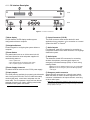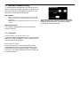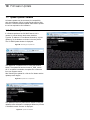
1
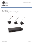
DDS 5900
User Manual
DDS 5900 Digital Discussion System
© 2014 Shure Incorporated
27Axxxxx (Rev. xx)
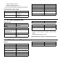
1 Table of Contents
1 Table of Contents
3
2 Important
2.1 Important Safeguards 2.2 Compliancy 2.3 Cleaning 2.4 Repacking 2.5 Warranty 5
5
6
7
7
7
7 System Set up
7.1 Control Software 7.2 Security 7.3 Audio Settings 34
34
36
36
8 Running a Discussion
8.1 Language Translation 8.2 Assigning Names and Seat Numbers 8.3 Microphone Operation Modes 8.4 Maximum Speaker Setting 8.5 Managing Speakers from the Web Browser 41
41
41
42
43
44
3 DDS 5900 Digital Discussion System
3.1 Features 3.2 System Concepts 9
9
10
4 Component Overview
4.1 Central Unit 4.2 Discussion Units 4.3 Additional Compatible Equipment 11
12
15
9 Troubleshooting
9.1 Factory Default Reset 9.2 Event Report 45
45
45
5 Installation
5.1 Rackmounting the CU 5.2 Cable Requirements 5.3 Connection Diagrams 5.4 Increasing Cable Length with Data Repeaters 5.5 Power Requirements 5.6 Connecting Discussion Units 5.9 Install the DC 5900 F 19
19
19
20
24
25
27
28
10 Firmware Update 10.1 Update System Firmware 10.2 Firmware Update 46
46
46
11 External Control Protocol
11.1 General Protocol Behavior 11.2 Microphone Control 11.3 Audio Control 47
47
48
51
6 Using the Discussion Units
6.1 Program the User Type 6.2 Controlling the Discussion Unit 6.3 Monitoring 30
30
31
31
12 Technical Specifications
12.1 System Specifications 12.2 CU 5905 Specifications 12.3 DC 5980P Discussion Unit 12.4 GM 59xx Gooseneck Microphones 12.5 Connection Details 53
53
53
54
54
54
18
2 Important
2.1 Important Safeguards
1.Read these instructions - All the safety and operating
instructions should be read before the apparatus or
system is operated.
2.Keep these instructions - The important safety
instructions and operating instructions should be
retained for future reference.
3.Follow all warnings - All warnings on the apparatus
and in the operating instructions should be adhered to.
4.Follow all instructions - All instructions for installation
or use/operating should be followed.
5.Do not use this apparatus near water - Do not use
this apparatus in a water or moistures environment - for
example, near a bath tub, wash bowl, kitchen sink, or
laundry tub, in a wet basement, near a swimming pool,
in an unprotected outdoor installation, or any area which
is classified as a wet location.
6.Warning: To reduce the risk of fire or electric shock,
do not expose this apparatus to rain or moisture
and no objects filled with liquids, such as vases,
should be placed on this apparatus.
7.Clean only with dry cloth - Unplug the apparatus from
the outlet before cleaning. Do not use liquid cleaners or
aerosol cleaners.
8.Do not block any ventilation openings. Install in
accordance with the manufacturer’s instructions
- Openings in the enclosure, if any, are provided
for ventilation and to ensure reliable operation of
the apparatus and to protect it from overheating.
These openings must not be blocked or covered.
This apparatus should not be placed in a built-in
installation unless proper ventilation is provided or the
manufacturer’s instructions have been adhered to.
9.Do not install near any heat sources such as
radiators, heat registers, stoves, air ducts, or other
apparatus (including amplifiers) that produce heat.
10. Do not install the unit in a place exposed to direct
sunlight, excessive dust or humidity, mechanical
vibration or shock .
11. To avoid moisture condensations do not install the
unit where the temperature may rise rapidly.
12. Do not defeat the safety purpose of the polarized
or ground-type plug. A polarized plug has two blades
with one wider than the other. A grounding type plug
has two blades and a third grounding prong. The wider
blade or the third prong is provided for your safety. If
the provided plug does not fit into your outlet, consult an
electrician for replacement of the obsolete outlet.
13. Protect the power cord from being walked on
or pinched particularly at plug, convenience
receptacles, and the point where they exit from the
apparatus.
14. Only use attachments/accessories specified by the
manufacturer . Any mounting of the apparatus should
follow the manufacturer’s instructions, and should use a
mounting accessory recommended by the manufacturer.
15. Use only with the cart, stand, tripod, bracket or
table specified by the manufacturer, or sold with the
apparatus.
When a cart is used, use caution when moving the cart/
apparatus combination to avoid injury from tip-over - Quick
stops, excessive force, and uneven surfaces may cause the
appliance and cart combination to overturn.
16. Unplug this apparatus during lighting storms
or when unused for long periods of time . – Not
applicable when special functions are to be maintained,
such as evacuation systems.
17. Refer all servicing to qualified service personnel.
Servicing is required when the apparatus has been
damaged in any way, such as power-supply cord or
plug is damaged, liquid has been spilled or objects
have fallen into the apparatus, the apparatus has
been exposed to rain or moisture, does not operate
normally, or has been dropped.
18. Replacement Parts - When replacement parts are
required, be sure the service technician has used
replacement parts specified by the manufacturer or
having the same characteristics as the original part.
Unauthorized substitutions may result in fire, electric
shock or other hazards.
19. Safety Check - Upon completion of any service or
repairs to this apparatus, ask the service technician to
perform safety checks to determine that the apparatus is
in proper operating condition.
20. Overloading - Do not overload outlets and extension
cords as this can result in a risk of fire or electric shock.
21. Power Sources - This apparatus should be operated
only from the type of power source indicated on the
marking label. If you are not sure of the type of power
supply you plan to use, consult your appliance dealer
or local power company. For apparatuses intended to
operate from battery power, or other sources, refer to
the operating instructions.
22. Power Lines - An outdoor system should not be
located in the vicinity of overhead power lines or other
electric light or power circuits, or where it can fall into
such power lines or circuits. When installing an outdoor
system, extreme care should be taken to keep from
touching such power lines or circuits, as contact with
them might be fatal.
2.1.1 Labels
“Lightning Flash Symbol” with the lightning flash with
arrowhead symbol within an equilateral triangle, is intended
to alert the user to the presence of un-insulated "dangerous
voltage" within the product enclosure that may be of
sufficient magnitude to constitute a risk of shock to persons.
2.1.2 Note for Power Connections
Check that the voltage of your local power supply is within
the operating voltage of the unit. If a voltage conversion is
required, consult your DIS dealer or qualified personnel.
Set the Power switch to ‘Off’ if it is not used for several
days.
Important: The equipment must be connected to
earth (ground)
The wires in the main lead supplied with the equipment are
colored in accordance with the following codes:
• Green-and-yellow Earth (Ground)
• Blue Neutral
23. Object and Liquid Entry - Never push objects of any
kind into this apparatus through openings as they may
touch dangerous voltage points or short-out parts that
could result in a fire or electric shock.
Never spill liquid of any kind on the apparatus. Should
any liquid or solid object fall into the cabinet, unplug the
unit and have it checked by qualified personnel before
operating it further.
“Exclamation Point Symbol” with the exclamation point
within an equilateral triangle is intended to alert the user
to the presence of important operating and maintenance
(servicing) instructions in the literature accompanying the
product.
• Brown Live
• The green-and-yellow wire must be connected to the
terminal in the plug marked with the letter E or with the
safety earth symbol or marked with green-and-yellow
color.
• The blue wire must be connected to the terminal marked
with the letter N or marked with black color.
• The brown wire must be connected to the terminal
marked with the letter L or marked with red color.
• For pluggable equipment, the socket-outlet shall
be installed near the equipment and shall be easily
accessible.
2.1.3 Power Disconnect
Apparatuses with or without On/Off switches have power
supplied to the apparatus whenever the power cord is
inserted into the power source; however, the apparatus
is operational only when the On/Off switch is in the On
position. The power cord is the main power disconnect for
all apparatuses.
2.2 Compliancy
The equipment has been tested and found to comply with
the limits of the following standards for digital devices:
• EN55103-1 (Emission)
• EN55103-2 (Immunity)
• EN60065 safety
• UL6500 safety
The device complies with part 15 of the FCC rules.
Operation is subject to the following conditions: (1) The
device may not cause harmful interference, and (2) the
device must accept any interference received, including
interference that may cause undesired operation.
These limits are designed to provide reasonable protection
against harmful interference when the equipment is
operated in residential, commercial or light industrial
environments. The equipment generates, uses, and can
radiate radio frequency energy and if not installed and
used in accordance with the user manual it may cause
harmful interference to radio communications.
You are cautioned that any changes or modifications
not expressly approved in this manual could void your
authority to operate this equipment.
Operation of this equipment in residential area is likely to
cause harmful interference in which case the user will be
required to correct the interference at his own expense.
Intentional or unintentional changes or modifications
not expressly approved by the party responsible for
compliance shall not be made. Any such changes or
modifications could void the user’s authority to operate the
equipment.
If necessary, the user should consult a dealer or an
experienced radio/ television technician for corrective
action.
This is a Class A product. In a domestic
environment this product may cause radio
interference in which case the user may be
required to take adequate measures.
2.3 Cleaning
To keep the cabinet in original condition, periodically wipe
it down with a soft cloth. Stubborn stains may be removed
with a cloth lightly dampened with a mild detergent
solution. Never use organic solvents such as thinners or
abrasive cleaners since these will damage the cabinet.
2.4 Repacking
Save the original shipping box and packing material; they
may be used to ship the unit. For maximum protection, repack the unit as originally packed from the factory.
2.5 Warranty
The units are covered by a 24 month warranty against
defects in materials or workmanship.
3 DDS 5900 Digital Discussion System
The DDS 5900 Digital Discussion System is a conferencing solution with plug-and-play setup and online discussion
management. With excellent audio quality and programmable touch-button controls, compact microphone units facilitates
clear communication in large groups and meeting spaces. The system manages up to eight talkers at a time and
dedicates two channels for interpretation, supporting bilingual events without additional equipment.
The DDS 5900 Digital Discussion System is comprised of one central unit, the control browser, and up to 250 discussion
units. Supporting multiple user types, a gooseneck microphone, loudspeaker, and control buttons are combined in a
compact discussion unit. With highly flexible layout options and a choice of tabletop or flushmount units, the system
seamlessly integration into a wide range of professional environments, such as:
• Corporate meeting rooms
• City councils and regional government bodies
• Educational institutions
• Courtrooms
• Non-profit organizations
• Videoconferencing
3.1 Features
Clear, Natural Communication
DDS 5900 discussion units enhance group communication, allowing natural conversing volumes to be heard in large
meeting spaces. Gooseneck microphones provide excellent speech isolation, while the LED light ring indicates who is
talking. A 24-bit digital audio signal is transported to each discussion unit for real-time monitoring from the loudspeaker.
Several microphone operation modes provide manual and automatic ways of controlling who speaks.
Sleek, Professional Design
Modern, low-profile design integrates into a variety of spaces, from historic buildings to contemporary boardrooms.
DDS 5900 discussion units are intuitive and functional, reducing clutter and increasing tabletop workspace. Two model
variations are available to support the needs of any event:
•Compact flushmount unit for permanent installation
•Portable unit for quick setup and easy tear-down
Flexible Setup and Easy Installation
The DDS 5900 system uses a proprietary protocol to transport digital audio, control data, and power over a single cable.
Up to 250 units can connect in serial with a Cat5e cable, easily scaling to support the event. To add participants to the
discussion, simply connect additional units to anywhere in the chain.
Remote Management
For comprehensive system management, open the system control interface using a web browser. The interface adds
system configuration and discussion setup capabilities, enabling an administrator to prepare the discussion with
participant names and seat numbers. The chairman or moderator uses a dedicated page for speaker management
during the discussion. The browser interface operates on any computer or tablet connected to the network.
The system is compatible with Crestron, AMX, and other programmable controllers. The CU easily interconnects with
teleconferencing equipment and digital signal processors.
3.2 System Concepts
The DDS 5900 Discussion system is an important communication tool for a large group of people and meetings in large
spaces. Participants use the discussion unit microphone and loudspeaker to discuss using natural speech levels.
3.2.1 The Discussion Unit: A Personal Sound System
The DDS 5900 Discussion Systems improves communication amongst a group of people by combining the microphone,
loudspeaker, interpretation audio, and user controls in an integrated unit. When a participant speaks, their voice is heard
at the other the discussion units' loudspeaker.
Traditional sound systems support the communication of one or two speakers to a crowd of people. In this system, it is
impossible to have the dialog required in a discussion setting.
3.2.2 Discussion Participants and Roles
The DDS 5900 discussion unit is programmable to support different functions required by different people involved in the
discussion. For example, as the moderator of the discussion, the chairman has an extra control that immediately turns off
all delegate microphones. In a typical event, there are three categories of participants:
The following is an overview of each participant role and how they function in a typical discussion.
Delegate (member, participant)
The majority of participants fall into this category. The delegate role is for anyone involved in the discussion that is not
a chairman or interpreter. Delegates use the discussion unit to speak and listen to other participants. Depending on the
discussion is settings, the delegate need to request to speak before the microphone is activated by the Chair.
• Up to 250 delegates can be connected to a single system.
Chairman (chair, moderator, president)
The chairman, or simply the Chair, is the moderator of the discussion. Typically seated at the head of the meeting space,
the Chair has the ultimate authority over who is speaking. Using the browser interface, the moderator has ability to turn
microphones on or off for specific participants, and view the order in which participants request to speak. Providing
immediate control of the discussion, an 'all-delegate off' button is available on discussion units programmed to chairman
mode.
• There is typically only one Chair for each event, though more can be added.
Interpreter (translator)
When an additional language is required, an interpreter uses the discussion unit to translate the discussion. Interpreters
select from one of two channels to transmit to other participants speaking the same language. This system supports
bilingual, two-way discussion, facilitating the back-and-forth communication between delegates speaking two different
languages.
• Up to 32 interpreters stations are supported in a single system.
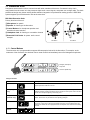
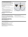
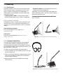
4 Component Overview
① Central Unit
② Discussion Units
1
2
③ Control Interface
Figure 1. DDS 5900
The DDS 5900 Discussion System consists of the following components:
① CU 5905 Central Unit
The central unit (CU) is the processor for the DDS 5900 system. It provides power and control to the discussion units,
analog audio inputs and outputs for external equipment, and a webserver that hosts the browser interface for remote
system control. Each system uses a single CU.
② Discussion Units
Participants use the discussion units to speak and listen to other members of the event. A microphone, loudspeaker, and
channel selector are provided for each unit. Units connect in serial, simplifying setup by transporting power, audio, and
control data on the same cable. Up to 250 units can be connected in any order, regardless of configuration. There are
two models of discussion units:
DC 5980 P Portable Discussion Unit
All-in-one unit that sits on the table surface. It is required for supporting language interpretation.
DC 5900 F Flushmount Discussion Unit
The flushmount discussion unit installs unobtrusively into a table or podium. The modular unit adds functionality depending on the
components.
③ Browser Interface
The browser interface provides comprehensive setup and discussion management for the DDS 5900 system. It opens in
a web browser from a computer networked with as the CU. Use the interface to manage microphones, assign names and
seat numbers to delegates, and advanced system configuration
4.1 Central Unit
The CU 5905 Central Unit (CU) provides the intelligence for system of up to 250 discussion units. It processes audio and
control signals from each discussion and interpreter unit, and distributes audio to other participants for listening to the
discussion.
CU 5905 CU has the following features:
• Controls a system of up to 250 discussion units and 32 interpretation units
• Transports secure audio signal with a proprietary codec algorithm
• Supplies power for up to 60 discussion units
• Supports two (2) interpretation channels for bilingual discussions
• Provides four (4) XLR connectors for connection to PA systems, audio mixers, audio recorders, or a language
distribution system
• Provides two (2) audio inputs for connecting wireless microphones, processed audio signals, an emergency broadcast
message, or music during meeting breaks
• One rack unit (1RU) installs into a standard 19" rack
Audio Input
Remote Control
ULXD2
on
1
2
1
2
1
2
1
2
Audio Outputs
1
2
1
2
1
2
1
2
1
2
11
22
Control of 250 discussion units
Figure 2. System Hub
The CU connects external equipment to the DDS 5900 system
4.1.1 CU Interface Description
Front
Back
Figure 3. CU 5905 Central Unit
① Menu display
A 2x20 character OLED-display enables system
configuration without a computer.
② Navigation Buttons
5-button keypad for configuring the system without a
computer.
③ Power Button
The power button turns on or off the central unit. All
connected discussion units and power supplies will
automatically power on.
•Green = powered on
•Red = powered off but connected to power supply
•Off = no power supply is connected to the unit
④ Power Supply Connector
Threaded connector secures to the PS CU power supply.
⑤ Chain outputs
Two RJ45 jacks are available for connecting the discussion
units, forming the DCS-LAN. The DCS-LAN chain safely
carries digital audio, control data, and power over the
same cable. The CU operates a single mix from the two
separate discussion unit chains, enabling more flexible
installations and system connections.
Important: Only connect DDS 5900 discussion units to this output.
⑥ Control Connector (TCP/IP)
The RJ45 connector allows access the built-in web
application from a computer, or for connection to a control
system like AMX® or Crestron®.
⑦ Audio Outputs
Four balanced, male XLR connectors for connection to
PA systems, audio mixers, audio recorders, or a language
distribution system.
⑧ Audio Inputs
Two balanced, female XLR connectors for connecting
wireless microphones, processed audio signals, an
emergency broadcast message (EEM), or music during
meeting breaks.
•Input 1: Connect an additional audio source; gain is adjustable.
•Input 2: Connect an Emergency Evacuation Message (EEM)
audio signal.
⑨ Emergency switch connector
A terminal block connector for a 'normally open' switch.
When the switch is closed, the audio signal on the 'In 2'
connector is distributed to all output channels, overriding
all other audio inputs.
Note: There is no volume control available for setting the volume on 'In 2'. The
volume has to be set at the equipment generating the "Emergency Evacuation
Message (EEM)" audio signal.
4.1.2 Simplified Audio Schematic
Figure 4. DDS 5900 Digital Discussion System Audio Schematic
4.1.3 Menu Navigation
The CU 5905 provides controls from the front panel for
system setup and configuration. Use the 5-button keypad
to navigate the menu and change settings.
Menu path
Settings
The figure below gives an overview of the menu structure.
• Use arrow buttons to cycle through menu items
• Press Enter button to navigate to an editable field.
• Use up/down buttons to cycle through the available
values
• Press Enter button to save changes
Figure 5. Menu Overview
4.2 Discussion Units
Participants use discussion units to communicate with other members of the event. Connected in daisy-chain
configuration from the central unit, they transport digital audio, control signals, and power over a single cable. The sleek,
professional design and minimal cabling allows seamless integration into professional meeting spaces. A DDS 5900
system supports up to 250 discussion units at the same time.
DDS 5900 Discussion Units
Primary functions of the unit:
① Microphone: for speech
② Speaker: for listening to the discussion
③ Control Buttons: for microphone operation and
translation channel selection
④ Headphone Jack: for listening to a translation channel
⑤ Base with RJ-45 Jacks: for power, audio, control
transport
DC 5980 P
DC 5900 F
4.2.1 Control Buttons
The discussion unit is programmable to support different people involved in the discussion. For example, as the
moderator of the discussion, the chairman has an extra control that immediately turns off all delegate microphones.
1
2
Delegate (Participant)
Interpreter
1
2
Chairman (Moderator)
1
2
Using the Controls
Button
Description
Speak
Press to turn on the microphone or add the user to the request list, depending on the
system operation mode set in the CU.
Mute (delegate
only)
Press and hold to temporarily mute the audio from the microphone. During this time, the
delegate will retain speaking privileges but the microphone will not pass audio to the floor
sound. The microphone light ring is off during mute.
Delegate Off
(chairman only)
The chairman has the ability to immediately turn off all delegate microphones with this
button. At that time, only the chairman has speaking privileges.
Channel Selector
Headphone
Volume
1
2
Scroll through the channels to select an audio source for monitoring on headphones.
Channels 1 and 2 select a language translation feed; floor sound is selected when the
LEDs are off. When the unit is programmed for an interpreter, this select the transmitting
channel.
Increase or decrease the volume of the headphone audio signal.
4.2.2 Model Variations
DC 5980 P Portable Discussion Unit
Sits on the tabletop without drilling or cutting the surface,
and easily dismantles for system reconfiguration. Features
include an integrated speaker, rear-exit cable routing, and
operation as an chairman, delegate, or interpreter unit.
Integrated Design
The following features are integrated in the unit
Translation Monitoring
Listen to a translation channel using the headphone output
Sound Reinforcement
Loudspeaker for listening to other talkers
Microphone Variations
Compatible with all DIS microphones
Figure 6. DC 5980P Portable Discussion Unit
DC 5900 F Flush-Mounted Discussion Unit
Installs permanently into a table or podium. A low-profile
design conceals the base and cabling below the tabletop
surface. This unit can operate as a chairman or delegate.
Modular Design
MX405RLP
Gooseneck Microphone
Functionality is scalable by adding or subtracting parts
Translation Monitoring
Two front plate options are available:
•FP 5981 F: speech with translation monitoring
•FP 5921 F: speech only
Sound Reinforcement
Add the optional LS 5900 F loudspeaker
LS 5900 F
Loudspeaker
AC 5901
Shure Microflex Microphone Adapter
Microphone Variations
In addition to DIS microphones, a Shure Microflex Gooseneck
is compatible with the flushmount unit by connecting the AC
5901 adapter
FP 5981 F
Front Plate
DC 5900 F
Base Unit
Figure 7. DC 5900 F Discussion Unit
4.2.3 Gooseneck Microphones
The DIS GM 592x microphone delivers excellent audio
performance with a frequency response specifically
tailored for speech. The gooseneck is on the base of the
microphone, providing flexible positioning. A red LED ring
at the top of the microphone clearly indicates when the
microphone is active and the participant is speaking.
Two models are available:
• GM 5923: 40 cm (16 in.)
• GM 5924: 50 cm (20 in.)
Figure 8. DIS GM 592x
4.2.4 Shure MX 400 Gooseneck
The DC 5900 F Flushmount discussion unit functions
with Shure MX 400 RLP series microphones. Featuring
legendary Shure audio performance and build quality,
CommShield® Technology eliminates noise caused by
smart phones, tablets, WiFi and other RFI. A red LED ring
at the top of the microphone clearly indicates when the
microphone is active and the participant is speaking. A
flexible gooseneck is on the top of the microphone.
Three models are available for the DC 5900 F Flushmount
Discussion unit:
• MX 405 RLP: 15 cm (6 in.)
• MX 410 RLP: 25 cm (10 in.)
• MX 415 RLP: 38 cm (15 in.)
Microphone Adapter
The AC 5901 microphone adapter enables the flushmount
discussion system to use the MX series microphone.
Simply screw the adapter to the bottom of the microphone,
and insert it into discussion unit.
Figure 9. Shure MX 4xx RLP
4.3 Additional Compatible Equipment
The following units are available to use in the DDS 5900
system:
Additional Power and Advanced Setup
EX 6010 Extension Unit
Extension power supply and data refresher provides four
chain outputs for 200 discussion units.
RP 6004 Repeater/Splitter
Refreshes data signal for long cable runs and provides four
additional outputs for discussion unit chains.
PI 6001 Power Inserter
Provides power for 40 discussion units.
JB 6104 Junction Box
Provides provides four tap-out points for discussion units.
RC 6000 Redundancy Controller
Enables the connection of a redundant CU 5905 central
unit to protect against power failures.
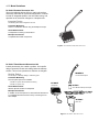
Using the Discussion Unit
Headphones
•DH 6021: Stereo on-ear headphones
•DH 6223: Stereo stethoscope headphones
•DH 6225: Mono ear-clip headphone
Microphones
•GM 6523: Gooseneck Microphone 40 cm (16 in.)
•GM 6524: Gooseneck Microphone 50 cm (20 in.)
•GM 6525: Gooseneck Microphone 63 cm (25 in.)
•GM 6622: Shotgun Microphone
Storage Boxes
•SB 5980: Ten pieces of DC 5980 P discussion units and GM 59xx
gooseneck microphones
5 Installation
Discussion units operate by connecting in serial from the
CU 5905. Power, audio, and data are transported over a
single Cat5e cable from one discussion unit to the next.
This topology enables flexible and inexpensive installation
for large groups of people.
5.1 Rackmounting the CU
Install the CU 5905 Central Unit in a standard 19” rack
using the supplied 19” brackets. Remove the screws
holding the top and bottom covers, then attach the
brackets to the front of the unit using the same screws.
5.2 Cable Requirements
Shure offers cables designed specifically for the DDS 5900
system. The Shure EC 6001 are high-quality Ethernet
cabling available various lengths from 0.5 m to 100 m.
Each cable has been tested to ensure the best system
performance. See the accessories section for ordering
information on the EC 6001-xx.
Shielded connector
Figure 10. EC 6001
5.2.1 Installed Cabling Recommendations
When designing a space with permanent cabling in the
floor or walls, terminate the cables to a patch panel. It is
more reliable (and easier) to crimp the cable to the female
shielded connecter on the panel. Then simply use short
jumper cables to connect to the discussion units.
The built-in fan draws air in on the left side and exhausts
air on the right, and so does not require extra space above
or below for cooling.
Cat5 Cable Requirements
Type
Cat5e (or higher) twisted pair
Shielding
F/UTP or U/FTP
Connector
Shielded RJ45
Weight
AWG 24
Bending Radius
>15mm
Maximum Cable
Length
•CU 5905 only: 120 m
•CU 5905 with repeater units: 420 m
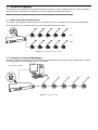
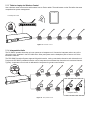
5.3 Connection Diagrams
The following system diagrams illustrate typical hardware connections to the CU 5905 Central Unit. Actual installations
may use different combinations of hardware, but follow the general concepts outlined below.
Note: Flushmount and portable discussion units are interchangeable in the following drawings.
5.3.1 Basic Setup with Discussion Units
The system is fully operational without the use of a computer. Use the CU navigation screen to set up the installation.
Use one or both A B Chain outputs on the CU to connect the discussion units in series.
Chain A
Chain B
Figure 11. Basic System with Two Chains
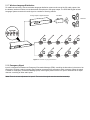
5.3.2 Computer for Advanced Management
Connect a computer to the central unit for comprehensive management of the system through a web browser. Connect
an Ethernet cable from the dedicated LAN port to a computer.
CU LAN port to computer
Figure 12. Computer Control
5.3.3 Tablet or Laptop for Wireless Control
Use a wireless router to access the web browser from an iPad or tablet. The web browser on the iPad offers the same
comprehensive system management.
CU LAN port to router
1
2
1
2
1
2
1
2
1
2
Figure 13. Wireless Control
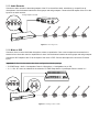
5.3.4 Interpretation Units
The DC 5980 P portable discussion unit can operate as a interpreter unit. Connect the interpreter units to any of the
discussion units, anywhere in the DCS-LAN chain. Other participants use the headphone jack to listen to one of the
translation channels.
The DDS 5900 Discussion System supports bilingual discussion, routing a translation channel to each discussion unit.
Program the DC 5980 P portable discussion unit for interpreters that translated the discussion to the selected channel.
Typically, a separate room or booth is dedicated for interpreters for greater sound isolation.
Interpreter Stations
Figure 14. Interpretation Units
5.3.5 Audio Recorder
Connect an audio recorder to the analog outputs of the CU to record floor audio, translations, or a specific set of
microphones. Use the browser interface to select groups and assign outputs. Connect the XLR outputs of the CU to the
inputs of an audio recorder.
Analog outputs to recorder
Figure 15. Recording Audio
5.3.6 Mixer or DSP
Connect a mixer to control individual microphone volume or equalization. One or more outputs are connected to the
external mixer, where the control or equalization is done. Use the browser interface to select groups and assign outputs.
Connect the XLR outputs of the CU to the inputs of the mixer or DSP. Connect the output of the unit to the CU Audio
Input 1.
Important: If 'Out A' is also send to the mixer, configure the following settings:
• 'CU 5905 Setup > Audio > Loudspeaker Control > Microphone -> Loudspeaker' set to 'Off'.
• 'In 1 -> Out. A' is set to un-selected in the selection 'CU 5905 Setup Audio > Input/Output Control > Audio In 1'.
Figure 16. Inserting a Mixer or DSP
5.3.7 Wireless Language Distribution
For additional monitoring, connect a wireless language distribution system to the one of the CU audio outputs. Use
the browser interface to select to route the desired microphones to that group output. The DCS 6000 Digital Infrared
Language System transmits this audio signal to a number of listening stations.
Analog outputs to digital transmitter
IR radiator
Receivers
Figure 17. Wireless Language Distribution
5.3.8 Emergency Signal
Input 2 is designed to broadcast an Emergency Evacuation Message (EEM), overriding the discussion in the event of an
emergency. Connect a switch (normally-open) must be connected to the emergency switch connector. When the switch
is closed an "Emergency Evacuation Message (EEM)" audio signal present on the 'In 2' input is distributed to all output
channels, overriding all other audio inputs.
Note: There is no level adjustment for input 2. The level of the signal must be controlled externally.
5.4 Increasing Cable Length with Data Repeaters
A large discussion unit chain requires additional equipment
to ensure a reliable audio signal. The DDS 5900 system
transports audio and control data in packets using a
proprietary protocol. The CU 5905 tightly manages and
synchronizes these packets for the entire discussion unit
chain to avoid audio dropouts. The CU requires a strong
signal to properly synchronize a large number of units.
CU 5905
DC 5980 P
max.120 m
(393 ft.)
The CU supports 120 m of cable before requiring additional
equipment to strengthen the signal.
5.4.1 Cables over 120 m
There are two solutions to add cable distance
RP 6004
The RP 6004 strengthens the data and adds four additional
outputs. This unit does not add power to the chain.
EX 6010
The EX 6010 strengthens the data and adds four additional
outputs. This unit is supplies a separate power source from
each chain output.
Figure 18. Data Refreshers for Longer Cables
5.5 Power Requirements
For most installations, the CU 5905 supplies sufficient power for the discussion units. Depending on the setup, the CU
5905 supports anywhere from 22-48 units at a time without additional equipment.
To maximize the unit count without adding equipment:
• Use shorter cables. More units are supported when the distance is minimized between the CU and the discussion
units.
• Use both A B Chain outputs from the CU. Units must be divided evenly across each chain.
② Distance between participants
① Length from CU 5905 to first unit
Figure 19. Power Decreases when Cables Increase
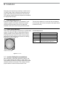
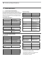
5.5.1 Units Supported by the CU 5905
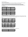
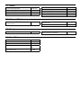
The following tables show how to connect the most discussion units without adding additional equipment.
Note: When using two chains, distributable the discussion units evenly across both chains to maximize unit count.
1 Meter between Discussion Units
2 Meters between Discussion Units
Distance to DU chain
One Chain
Two Chains
Distance to DU chain
One Chain
Two Chains
10
44
48
10
40
48
30
39
44
30
36
44
50
34
40
50
31
40
100
21
22
100
11
22
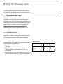
5.5.2 Alternative Setup
Without LS 5900 F Loudspeaker
The CU 5905 supports additional discussion units when the loudspeaker is not used with the DC 5900 F Flushmount
discussion unit. The numbers listed below are calculated with a DIS GM gooseneck microphone.
The flushmount units also operate with the Shure MX4xx series gooseneck microphones, though the power
consumption is slightly higher. Subtract six units from numbers below to determine the maximum number supported
by the CU 5905.
1 Meter between Discussion Units
Distance to DU chain
One Chain
Two Chains
10
57
64
30
51
60
50
44
58
100
21
42
2 Meter between Discussion Units
Distance to DU chain
One Chain
Two Chains
10
50
60
30
45
56
50
36
48
100
11
22
5.5.3 Using Junction Boxes
The JB 604 junction box adds four additional outputs to a point on the DCS-LAN chain. These four outputs are available
for short-run connections to DUs, protecting the DCS-LAN chain from technical failures or hot-plugging damage. A single
DU can connect to each JB output, with a maximum cable length of 10 m.
1 Chain
Length to First
DU
Length Between
each JB 6104
Number of JB 6104
Maximum
Number of DUs
10 m
1m
22
54
30 m
1m
20
39
50 m
1m
15
34
100 m
1m
7
21
2 Chains
Length to First
DU
Length Between
each JB 6104
Number of JB
6104
Maximum Number of
DUs
10 m
1m
26
54
30 m
1m
24
48
50 m
1m
24
48
100 m
1m
16
32
5.5.4 Adding Additional Power or Data Refreshing
Equipment can be added to the chain if the installation requires more discussion units.
Model
Additional Delegate Units
EX 6010 Extension Unit (4 outputs)
4x 64 units
PS 6001 Power Kit
57 units
5.6 Connecting Discussion Units
Discussion units are connected in series using the two
RJ45 ports. The connectors are interchangeable; simply
connect the previous discussion unit to one port, and the
other port connects to the next unit in the chain.
To protect the equipment, ensure that the Central Unit
(CU) is always off when connecting or disconnecting the
discussion units.
1.Make sure the CU power is turned off.
2.Connect the CU to the first discussion unit with the Cat5
cable.
3.Connect the rest of the discussion units in serial, using
the RJ45 jacks on the bottom of each unit.
4.Turn on the CU by pressing the power button. The
discussion units will power on. The unit is stable once
the control button LEDs stop flashing.
Note: Do not turn off CU power until the system
has stabilized
5.7 Attach the Touch-Button Overlay
Attach the touch-button overlay to each unit for basic
microphone control. The discussion units use soft buttons
that change functionality when programmed to different
unit types. Button overlays are supplied with the discussion
unit or with the central unit.
Warning: Overlays are not reusable. If a unit
needs to be reconfigured, carefully remove the
overlay and apply another one.
5.8 Securing the Microphone
To lock the microphone into place, use the supplied hex
key and turn counterclockwise.
DIS GM: Simply insert the microphone into the XLR
socket. Adjust the gooseneck for proper position.
Shure MX4xxRLP: Attach the AC 5901 XLR/Microflex
adapter to the microphone. Insert the adapter into the XLR
socket of the flushmount unit.
1.Choose an overlay for the unit.
2.Remove the protective paper from the back.
3.Place the overlay in the recess on the front of the unit.
5.9 Install the DC 5900 F Flushmount Discussion Unit
5.9.1 Installing the Base
The DC 5900 base installs directly onto a table or podium.
1.Determine the location of the microphone and cut a hole
with a diameter of 53 mm.
2.Use the base to mark the location for the screw and drill
the holes.
3.Secure the base to the table with the screws.
52 mm
Figure 22. Use Paper Clips for Removal
42 mm
5.9.4 Installing the Loudspeaker
1.Determine the location of the speaker (<1m from the
base to accommodate the cable) and cut a hole with a
52 mm diameter.
47 mm
53 mm
2.Insert the loudspeaker into the hole and connect the
loudspeaker cable to the base unit. Make sure the cable
is not pinched.
46 mm
106 mm
3.Align the loudspeaker with the base unit. Mark the
location for the screws, spaced exactly 78 mm apart.
5.9.2 Attaching the Front Plate
1.Align the front plate and place it onto the base.
2.Secure the plate to the base using the screws.
3.Snap the cover onto the front plate.
cover
4.Drill the holes and secure the speaker to the table with
the screws.
5.Snap the grill onto the loudspeaker cabinet.
6.Connect the cable from the loudspeaker to the DC 5900
F base
ø52 mm
ø1.8 mm
front plate
29 mm
base
30.5 mm
78 mm
Figure 21. Attaching the Front Plate
5.9.3 Removal
To remove the front plate:
1.Locate the two holes on each side of the front plate.
2.Insert a paper clip in each hole to release the cover.
3.Pull up on the cover to separate the pieces.
4.Unscrew the front plate from base unit.
91 mm
Figure 23. Bottom of LS 5900 F
6 Using the Discussion Units
Once the system as been properly connected, power on
the central unit to distribute power to the discussion units.
6.1 Program the User Type
DDS 5900 discussion units are programmable, changing
the function of the control buttons to support different
user types. The three types are chairman, delegate, or
interpreter, each requiring unique control functionality. unit
The setting is stored in the unit, and persists after a power
cycle or when connecting to a system for the first time.
Note: Flushmount units are not programmable as
interpreter stations. Use the portable DC 5980 P unit
for transmitting the translation.
6.1.1 Flushmount Units
To program the flushmount DC 5900 F discussion unit as
a chairman or delegate, simply attach the button overlay.
The overlay contains an embedded chip that automatically
programs the unit with the correct button functionality.
6.1.2 Portable Unit
Program the portable units by pressing the volume buttons
and scrolling to the desired mode.
1.Power on the unit by properly connecting it to the DCSLAN chain.
2.Press and hold the '-' and '+' volume buttons. The
Speak light flashes to indicate the unit is ready for
programming.
3.While continuing to press the volume buttons, press the
channel scroll to the unit type. The type is indicated by
the combination of channel LEDs; see the table below.
Changing Unit Type
Unit Type
Ch. 1
Ch. 2
Delegate with mute
Off
Off
Delegate without mute
On
Off
Chairman
Off
On
Interpreter
On
On
6.2 Controlling the Discussion Unit
DDS5900 discussion units are programmable during setup
to support the role of each member of a meeting.
6.2.1 Chairman
As the leader of the event, the chairman has several
unique features enabled on the discussion unit.
• Delegate Control: For meeting management, the
chairman uses this button to instantly turn off all delegate
microphones and clear the Speaker list.
6.2.2 Delegate
Delegates units are a collection of microphones that
contribute to a mix, called the floor mix. The number of
delegate speakers at one time is limited, requiring several
speech buttons on the discussion unit:
• Speaking: Turns on the microphone or adds the
user to the request queue, depending on the system
settings. When the microphone is turned on, the red LED
illuminates on the microphone. When the microphone
is in the queue list, the Speak LED on the unit will
illuminate green and flash when the unit is next in the
request queue.
6.2.3 Interpreter
The primary function of the interpreter unit is to translate
the discussion into a foreign language. Participants that
do not speak the native language of the discussion rely on
the interpreter to participate. Interpretors listen to the floor
sound
• Translation Channel Send: The interpreter uses the
channel selector button to send translated audio over
one of the two channels.
• Speaking Rights:The chairman can always turn on the
microphone, overriding delegate units even if it exceeds
the maximum number of open channels. Therefore there
is no mute button: the chairman simply presses the
Speak button to turn the microphone on and off.
• Mute Button: Temporarily mutes the audio from the
microphone. While the button is pressed, the delegate
retains speaking privileges but the microphone will not
pass audio to the floor sound.
Interpretation stations can only be assigned to the Portable
5980P discussion unit.
6.3 Monitoring
6.3.1 Floor Sound
A speaker available in each unit for sound reinforcement
of the discussion. When a microphone is turned on, the
signal is routed to all discussion unit loudspeakers. To
avoid feedback, the loudspeaker is turned off when that
microphone is active.
• Flushmounted DC 5900 F: The flushmount system
requires the attachment of the LS 5900 F loudspeaker.
• Portable DC 5980 P: Each portable discussion unit
includes an attached loudspeaker.
Additionally, floor sound is available at the headphone
output of discussion units*. The floor sound is selected
when the channel LED is off.
*Excludes flushmount units with the FP 5921 F front
plate. These are
6.3.2 Loudspeaker Adjustment
Loudspeaker volume is a system setting that applies to all
connected units. Volume adjustment is attenuation only,
ranging from -0 dB (no attenuation) to mute. To adjust the
volume:
From the Browser Interface
Go to the Loudspeaker Control page (Audio >
Loudspeaker Control)
From the CU
Scroll to the Loudspeaker Menu (loudspk. control >
loudspk. volume > db
Figure 24. Use the Loudspeaker for Sound Reinforcement
6.3.3 Language Interpretation
Two channels of language interpretation are supported
in the DDS 5900 system for delegates and chairmen.
Translation audio is available at the headphone connector
for all portable DC 5980 P and flushmount DC 5900 F units
with the FP 5981 F front plate.
To listen to one of the channels, follow these steps:
1.Connect headphones to the headphone jack on the side
of the discussion unit.
2.Select a channel by pressing the selector buttons on the
front of the unit. When no channel LED is illuminated,
the floor sound is selected.
3.Adjust the audio level of the headphones using the
volume buttons.
Figure 25. Use Headphones for Listening to Language Translation
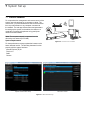
7 System Set up
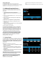
7.1 Control Software
For comprehensive management and remote control of the
system, open the web app on a computer or tablet. The
Central Unit (CU) hosts a webserver that can be accessed
from any web browser on any computer connected to
the network. The web app offerers advanced parameters
for setting up the system, and enables the chairman or
moderator to manage microphones using participant
names and seat numbers.
Note: The computer network is separate from the
discussion unit network (DCS-LAN).
System Requirements
For best performance, always update the browser to the
latest released version. The following browsers function
properly with the system interface:
Figure 26. Connect to the CU 5905
Internet Explorer (IE) 8+
Firefox 10+
Safari
Chrome
Discussion Control
System and Discussion Setup
Figure 27. DDS 5900 Web App
7.1.1 Connecting for the First Time
Follow these instructions to open the browser interface on
a computer for the first time.
4.Acquire an IP address by selecting Dynamic from the
LAN Setup > Acquire IP addr. window.
1.Connect the computer to the TCP port on the CU 5905.
5.View the IP address: LAN Setup > IP address setup.
2.Power on the equipment.
6.Open the internet browser in the computer.
3.Assign the computer to automatically obtain an IP
address. This enables the computer to automatically
connect to the CU.
7.Type 'http://IP-address', where 'IP address' is the
address noted from the CU 5905.
8.The CU 5905 browser interface opens.
7.1.2 Assigning the Network Address
Access to the DDS 5900 interface is available from two
network addresses: IP address and hostname. Typing
either address into a browser will access the interface of
the connected CU.
7.1.3 IP Address
Select 'Dynamic' if the CU is connected to a network with
a DHCP server. Otherwise select 'Static' and assign a
fixed IP address to the CU. Default IP configuration is
"Dynamic".
7.1.4 Hostname
The hostname is a user-defined name can be assigned
to the device to access the browser instead of using the
IP address. The hostname is titled in a logical manner
to easily identify the component on the network. More
importantly, the hostname will not change on its own
(unlike the IP setting), making it ideal for bookmarking.
For example, if the system is set up in the primary meeting
room, the hostname could be called, "MainRoom". The
address would be: http://mainroom.local
7.1.5 Language Setting
The browser interface is supported in a variety of
languages. Go to System > Language to select the desired
language.
Crnogorski
Srpski
Albanian
Shqip
Arabic
ةيبرعلا ةغللا
Bosnian
Bosanski
Bulgarian
български
Chinese (Simplified)
中文(简体)
Chinese (Traditional)
中文(繁體)
Croatian
Hrvatski
Danish
Dansk
English
English
French
Francais
German
Deutsch
Greek
Ελληνική
Icelandic
Íslenska
Select 'Apply Changes' to save the changes made.
The actual IP address can be found in this screen or by
using the interactive menu on the CU 5905:
LAN setup
> IP address setup > IP address > Actual IP address.
1.Go to the LAN Setup page (System > LAN Setup).
2.Under CU hostname, select the default name and delete
it.
3.Enter the new hostname.
4.Select the Apply Changes button to save the name.
5.Check the address by typing into the browser:
http://hostname.local
6.If desired, bookmark the page.
Italian
Italiano
Japanese
日本語
Korean
한국인
Macedonian
македонски
Montenegrin
Црногорски
Norweigen
Norsk
Persian
یسراف
Polish
Polski
Portuguese
Português
Russian
русский
Serbian
Српски
Slovenian
Slovenski
Spanish
Español
Swedish
Svenska
Thai
ภาษาไทย
Vietnamese
Tiếng Việt
7.2 Security
DDS 5900 components use a proprietary codec algorithm
to prevent unauthorized devices from listening to the
audio signal. To further protect the discussion, assign a
password to the browser interface and enable security
features on wireless routers.
7.2.1 Password Protect the Browser Interface
Assign a password to restrict access to the browser
interface. A password will enable only an administrator or
technician to change system and meeting settings.
1.Connect a computer to the DC 5905 Central Unit (CU).
2.Access the browser interface using the CU hostname or
IP address.
7.2.2 Removing the Password
To clear the password access to the CU, restore factory
default settings.
Note: Resetting to factory defaults will erase all delegate, system, and IP settings.
From the Hardware
a)Go to the front panel of the CU.
b)Scroll the main menu to Restore Factory Defaults
c)Press the center button to enter menu
7.2.3 Isolating the Network
For maximum security, isolate the DCS-LAN network with
a dedicated computer or a protected router.
• Dedicate one computer for DDS 5900 control. Connect
it directly to the CU LAN port. This ensures that wireless
devices cannot access the IP address of the control
software.
• If multiple computers or tablets are required, assign a
password encryption for the router. The most effective
standard is the Wireless Protected Access II (WPA2),
which uses Advanced Encryption Standard (AES) for
encryption. Reference the router user guide to set it up.
3.Go to the Security page (System > Security)
4.Enter a valid user name and password.
5.Select Change Password to save the login information.
Note: The user name and password are deleted
when the system is reset to factory default settings.
d)Press the center button again to confirm the reset.
e)Wait for the system to reboot. The computer will lose connection
to the browser interface during this time.
From the Browser Interface
f) Open the CU browser interface
g)Go to Configuration > Factory Defaults
h)Select the Reset button to reset the system.
i) Wait for the system to reboot. During the reboot process, the
computer cannot access the browser interface.
7.3 Audio Settings
Use the DDS 5900 audio diagram as a reference when
making audio adjustments.
7.3.1 Loudspeaker
7.3.2 Volume
Volume of the loudspeakers can be turned down to
accommodate quieter installations. The attenuation setting
applies all connected discussion units in the system.
• Browser Interface: Audio > Loudspeaker Control >
Loudspeaker Volume
• CU: Loudspk. control > Loudspk. volume
7.3.3 Audio Source
Group A is always used as the source for the discussion
unit loudspeakers. By default, all discussion units are
routed to this group.
Removing a Discussion Unit
Deselect Group A to remove a discussion unit microphone
from the loudspeaker bus. Go to Audio > Audio Output >
Group Setup
Tip: Adjust several microphones at once using the
dropdown arrow next to Group Setup.
Add an Audio Input
An additional audio source can be routed to the
loudspeakers. Make sure the loudspeaker box is selected
at the Audio > Input/Output Control > Input Control.
7.3.4 Adding an External Audio Source
For teleconferencing or internet calling, use the CU
audio input 1 to add the additional audio source to the
discussion.
1.Connect the audio output of a computer or
teleconferencing unit to the Audio Input 1 on the CU
5905.
2.Open the control browser to Audio > Input/Output Control
> Input Control.
3.Select the input gain according to the output of the
external device.
4.Make sure the Loudspeaker is selected (default).
5.Make sure Out A (Group) is unselected to avoid a
feedback loop.
6.Adjust the volume of the audio input for natural speech
levels at the discussion unit.
7.3.5 Emergency Audio Signal
To prepare for an emergency, connect an Emergency
Evacuation Message (EEM) audio signal to Input 2. A
block connector provides a 'normally open' switch that
when closed, the emergency signal is distributed to the
loudspeakers and all input and output connections.
Note: There is no volume control available for setting
the volume on 'In 2'. The volume has to be set at the
equipment generating the "Emergency Evacuation
Message (EEM)" audio signal.
7.3.6 Analog Outputs
To isolate certain microphones or translation channels, four
groups available for routing audio signals. Each group can
then be assigned a separate analog output for recording,
language distribution system, or teleconferencing unit, or
external PA.
Go to Audio > Audio Output > Group Setup.
• Group: Four separate groups are available for isolating
specific microphones
• Floor: All active microphones are routed to the floor
sound. If the Audio Input 1 has been assigned to the
loudspeaker.
• Channels 1 & 2: Interpretation channels can be sent to
a language distribution system.
Note: When 'Group' is selected for 'Out A', the 'Group
A' is the source for the three other outputs.
Note: If 'Floor, Ch.1, Ch.2' is selected for an output
(Out A, B, C or D), the corresponding group is
disabled in the 'Group Setup'
•Adjust the input gain according to the sound source (0 db or 10
db)
•Adjust the volume to the loudspeaker from 0 db to -40 db, or mute.
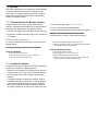
8 Running a Discussion
8.1 Language Translation
The DDS5900 system supports two channels of language translation. Interpreters use the portable DC 5980 P to monitor
the discussion and send translations to the rest of the participants.
1.Begin by programming the portable DC 5980 P as an interpreter station.
a) Power on the unit by properly connecting it to the DCS-LAN chain.
b) Press and hold the '-' and '+' volume buttons. The Speak light flashes to indicate the unit is ready for programming.
c)While continuing to press the volume buttons, press the channel button. Interpreter mode is set when both channel LEDS are illuminated.
2.Select one of the two channels for audio transmission. The channel LED will illuminate to indicate the selected
channel.
3.Program another DC 5980 P for the second language and select the other channel for transmission.
4.Select the language channel for each user, according to the spoken language.
Flushmount DC 5900 F units are not programmable as interpreter units.
8.2 Assigning Names and Seat Numbers
When the discussion begins, the chairman or discussion moderator will need to refer to the delegates by either name,
seat number, or both. The proper assignment of names and seat numbers is critical to ensuring the continuity of the
discussion.
When logging in with the browser interface to an installation for the first time, each delegate unit appears with its default
name. Units are automatically assigned a seat number. Chairman units also appear in the delegate setup page. Use the
delegate setup page to match the units to the anticipated seating chart.
1.Make sure all units are connected and functioning.
•Go to the System Status page for details System > System Status
•All properly connected delegate units are listed with a default serial and seat number automatically assigned by the software.
•If units are disconnected, they are marked with a yellow indicator in the list.
•The units can be removed from the list either individually or as a group by clicking the yellow button.
2.Reassign seat numbers to match the actual seat numbers in the room or on your seating chart.
a)Go to the Unit to Seat Relation page Configuration > Unit to Seat Relation.
b)Match the entries in the seat table to the corresponding units in the room by placing the cursor over the seat number field. The light ring on the
microphone flashes red.
c)Change the seat number by clicking in the field.
3.Draw a seating chart, or diagram, that represents the room. Number each seat that requires a discussion unit. Add
delegate names to the seating chart.
4.Go back to the Delegate Setup page (Configuration > Delegate Setup) and change the descriptions next to the assigned
seat numbers to the appropriate delegate names. Press enter to save the new name.
Reassign Seat Numbers
Add Delegate Names
8.3 Microphone Operation Modes
The operation mode determines how delegate
microphones function during a meeting. Several factors
may affect the meeting requirements and the manner in
which the meeting run: room size, number of participants,
formality of the event, and amount of technical support on
staff. The operation mode addresses these factors with
four presets to control the microphone behavior.
To change the mode:
• CU hardware: Delegate Setup > Operation Mode
• Browser interface: Operation > Operation Mode or from the
Microphone Control page.
Description of Operation Modes
The following is a description of each mode once the
Speak button is pressed:
Manual
Adds the delegate to a request queue that is managed by
the chairman. The Chairman selects delegate microphones
from the queue list, and turns them on and off. Manual
is the only mode in which the web browser is required to
manage speakers.
Auto (Automatic)
Automatically turns on the delegate microphone if there is
room in the speaker list. In this mode, there is no request
queue: if the Speaker List is full, the delegate microphone
does not turn on.
FIFO (First In, First Out)
Automatically turns on the delegate microphone if there
is room in the speaker list. Once the list is full, delegates
are placed into a chronological request queue. The
microphone turns on automatically once a space is open in
the speaker list.
VOX (Voice Activation)
The microphone automatically turns on when a speaker
talks into the microphone or presses the Speak button.
The microphone automatically turns off after the speaker
is finished. In this mode, there is no request queue: if the
Speaker List is full, the delegate microphone does not turn
on.
8.4 Maximum Speaker Setting
To improve speaker management and clarity of the audio,
there is a limit to the number of speakers at the same time.
Up to eight chairman and delegate microphones can be
open at once. There are several settings:
Max speakers
•Total: Total number of open delegate and chairman units. This
is the absolute maximum number of people that can address the
floor at once.
•Delegate: Number of delegates microphones that can be open at
one time.
Maximum Requests
Total number of delegates that can be in the request
queue at one time.
8.4.1 Scenarios
8.4.2 Chairman Can Speak At Any Time
Set the total number of speakers to one (1) higher than the
maximum number of delegates. If there are two chairmen,
set the number to two (2) higher.
8.4.3 Using FIFO Mode
First In, First Out (FIFO) mode automatically turns on
microphones based on a chronological queue list. This
mode works best if the maximum number of delegates is
set to one (1) so that the delegate must wait to speak until
the other is finished.
Note: Interpreter units are always open to support the
translation of the discussion. The following settings
do impact the interpreter stations.
8.5 Managing Speakers from the Web Browser
For increased control over the discussion, the chairman
uses web interface to activate microphones. The
Microphone Control page is a dedicated page for
controlling the speaker list and request queue. The
chairman can manually turn on/off microphones, or simply
monitor the list in an automatic mode. Using the interface,
the chairman can easily:
• Click on a delegate name to turn on the microphone, or
add them to the request queue.
• View who is speaking and who is waiting their turn to
speak
Begin by opening the browser interface. Select the
Microphone Control button from the main menu. The
dedicated page for microphone control will open.
Speaker List (Red)
The speaker list displays the name and seat number of
each active microphone. The list displays in chronological,
with the most recently activated microphone at the top
of the list. A red box turns on next to the seat number for
quick visual identification.
Request Queue (Green)
Delegates in this list are next up for speaking. Primarily
useful when operating in First In First Out mode (FIFO),
the queue chronologically lists all delegates that have
pressed their speak button. Once an opening is available
in the speak list, the delegate at the top of the queue list is
automatically turned on.
There are two main lists from the Microphone Control
page:
8.5.1 Chairman Control
The following buttons are available to the chairman for
controlling the delegate microphones:
Speak
Instantly turn on a delegate’s microphone. Select this
button to view all discussion units in the system, including
those in the request queue. Select a delegate to add them
to the Speak list.
Request
Add a delegate to the request queue to put them in line
for speaking. Select from any delegate in the system,
excluding the chairman.
Next On
Activates the delegate microphone at the top of the request
queue. If the maximum speaker count has been reached,
the new speaker replaces the last one on the list.
All Del. Off
Turns off all delegate units, leaving only the chairman in
the speaker list. The same button appears on the chairman
discussion unit.
All Req. Off
Removes all delegates from the request queue.
9 Troubleshooting
This section contains a simple troubleshooting guide.
It is intended to be used to troubleshoot problems due to incorrect installation. If more serious faults or problems arise,
the installer should contact a qualified technician.
The light rings on the microphone are constantly
flashing when installed in the units.
•Check the cables. Digital communication from the Central Unit to the Discussion
Units has not been established
•Ensure that all the connectors on all the cables are firmly inserted in the sockets on
the units
•Check that the feed cables from the Discussion Units are properly inserted into the
'DCS-LAN' socket on the CU 5905.
The 'Del. Off' button on the Chairman Unit does
not switch off the Delegate Units
•Check to make sure the unit is configured as a Chairman Unit
•Check to make sure the other units are configured as Chairman or Interpreter Units.
Please refer to 'Configuration of the Unit' section.
The audio from an Interpreter Unit cannot
be heard in the headphone of Delegate or
Chairman Units
•Check to make sure the unit is configured as an Interpreter Unit. Please refer to
'Configuration of the Unit' section.
•Check the headphone volume control on the units
•Check the channel selection on the Discussion Units
•Check that the headphone plug is firmly inserted in the headphone jack
•Check that the light ring on the microphone on the Interpreter Unit is illuminated and
that the gooseneck microphone is firmly inserted in the socket
There is no audio coming from the built-in
loudspeakers
•Check the 'Loudspeaker Volume' setting using either the interactive menu on the CU
or using the browser control.
•Check the setting 'CU 5905 Setup > Audio > Loudspeaker Control > Microphone ->
Loudspeaker' is set to 'On', using the browser control.
•Check the settings in 'CU 5905 > Audio > Audio Output > Group Setup' that the seats
are selected in 'Group A', using the browser control. 'Group A' is always used as the
source for the built-in loudspeakers. If a unit is not selected in 'Group A', the audio
from the unit will not be heard in the built-in loudspeakers.
There is no audio from the built-in loudspeakers
on one or more Delegate or Chairman Units
•Check in 'CU 5905 > Audio > Audio Output > Group Setup', using the browser
control. Make sure the seat is selected in 'Group A'. 'Group A' is always used as the
source for the built-in loudspeakers. If a unit is not selected in 'Group A', the audio
from this unit will not be heard in the built-in loudspeakers.
A microphone cannot be turned 'On'
•Check the settings 'Max Delegate Speaker' and 'Max Total Speakers'.
•Check the 'Operation Mode'.
The CU 5905 browser application will not open
on a PC or iPad
•Using the interactive menu on the CU, check the IP address: 'LAN setup/IP address
setup/IP address'. Use this IP address using the browser
•Verify that the CU5905 and the PC are connected to the same network
•Check the LAN cable connections
The CU 5905 browser application will not open
on an iPad
•Check the IP address, using the interactive menu on the CU: 'LAN setup > IP
address setup > IP address'. Use this IP address in the browser.
•Verify that the iPad is connected to the proper wireless access point
•Check that the CU 5905 is connected to the same network as the wireless access
point
9.1 Factory Default Reset
Note: Resetting to factory defaults will erase all delegate, system, and IP settings.
From the Hardware
a)Go to the front panel of the CU.
b)Scroll the main menu to Restore factory def.. Press the center
button to enter menu
c)Press the center button to select OK and confirm the reset.
d)Wait for the system to reboot. The computer will lose connection
to the browser interface during this time.
9.2 Event Report
To assist in troubleshooting, a system-wide report is
available from the moment the CU powers on. Go to
Diagnostics > Report and select Generate to view the report
in a new window. Save the file to the computer and print
a copy to best help the Shure support group diagnose the
issue.
From the Browser Interface
e)Open the CU browser interface
f) Go to Configuration > Factory Defaults
g)Select the Reset button to reset the system.
h)Wait for the system to reboot. The computer will lose connection
to the browser interface during this time.
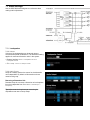
10 Firmware Update
10.1 Update System Firmware
A firmware update may be necessary for compatibility
with other hardware, which is performed through the web
browser. Follow the firmware update instructions to update
the unit as required for this installation.
10.2 Firmware Update
If a firmware update of the CU 5905 Central Unit is
needed, it is done through the browser interface:
Type the 'IP address' or 'Host Name' followed by '/cgi-bin/
update.cgi' in the browser as shown in the next picture.
The CU 5905 Update window is displayed:
Figure 28. Browsing for Update File
The update file is located on the PC using the 'Browse'
button. The update file has the format 'cu_5905_xxxxxx.
dis'. If an update is available, the update file is delivered
from your support source.
After selecting the update file, click the 'Go' button and the
update process begins:
Figure 29. Update File is Uploaded
The update process may take several minutes. During the
update process information is displayed. When the process
is finished the word 'Success' is displayed:
Figure 30. Update is Finalized
11 External Control Protocol
The DDS 5900 Digital Discussion System features an
Ethernet connection for the purpose of providing an
interface to control and monitor the system. By setting up
a simple (raw) TCP/IP socket connection to the CU 5905
Central Unit, control options are available.
This section describes the TCP/IP raw socket protocol for
communicating with the DDS 5900 Discussion System.
This protocol provides a short set of commands, enabling
a third part control application to monitor and/or control
system status of a DDS 5900 Discussion System.
Some examples of functionally available using the protocol:
• Setting a microphone in speak or in request
• Retrieving a list of seats available in the system.
This interface supports applications developed by
customers, so the protocol is deliberately kept simple. The
External Control protocol offers a means for supplementing
the control functionality available through the DDS 5900
Browser interface and the CU 5905 interactive display,
however some commands and settings available in the
browser interface and on the CU 5905 interactive display
are not available using the 'External Control Protocol'
Customer applications can include but are not limited to
AMX® or Crestron® room control systems, PC or micro
controller based applications, e.g., for button mimics and
camera control applications.
11.1 General Protocol Behavior
11.1.1 TCP/IP socket connection
A TCP/IP socket connection to the CU 5905 must be
established for the External Control protocol to become
available. Configuration of the CU 5905 connection to the
Ethernet must be defined from the CU interactive front
plate control/Browser interface and an IP address for the
CU 5905 must be assigned in the network.
Port Number = 3142
Choose either a static IP address or an IP address
assigned through DHCP. It is convenient to ensure, that
the CU 5905 ends up with the same IP address at each
start up.
Knowing the IP address of the CU 5905 a connection can
be set up using a simple terminal program like Putty.
Knowing the IP address, the only additional information
required for setting up a TCP/IP connection is the Port
Number:
Example: Test connection to CU via Putty®: If the
CU 5905 is assigned IP address 192.168.1.100, the
external application must connect the TCP/IP socket
to the address 192.168.1.100:3142.
1.Download at www.putty.org
2.Start Putty.
3.Insert IP address and Port Number.
4.Select 'Raw' for the Connection Type.
5.Press 'Open' to establish connection to the CU. Control
is now possible.
6.Type 'help' to see a list of commands available.
11.1.2 Command Structure (from External Control to CU 5905)
To control the CU an External Control sends commands to
CU 5905 included in command lines. Commands lines are
build up in a very simple manner:
Notice also, there is a space between the command and
data. If a command does not carry any data, space is
possible but not required.
<command><SP><data><CR>
<command><SP><data><LF>
The CU is not sensitive to upper/lower case.
<SP> Space - 0x20 = 32
<CR> Carriage return - 0x0D = 13
<LF> Line Feed - 0x0A = 10
Command lines are terminated by a Carriage Return
<CR> or Line Feed <LF> or both. In order to be able
to communicate with Windows systems, Linux systems
or other systems, the CU understands both types of
command line terminations.
Example:
mic_on 212<CR>
Turn on microphone at seat 212. Command = mic_on,
data = 212. The 'mic_on' command carries a seat number
as data.
11.1.3 Command Structure (from CU 5905 to External Control)
Command lines out of the CU 5905 are just as simple:
<command><SP><data><CR><LF>
<SP> Space - 0x20 = 32
11.1.4 Seat Numbering
Discussion Units are identified by means of a seat
numbers. Each Discussion Unit is assigned a seat number.
This is done automatically for all discussion units, when
they are connected to the CU 5905. The CU 5905 Browser
interface is used to change seat numbering.
11.1.5 CU 5905 Reply to Commands
Generally, a command from an external application is
replied to by the CU. But, reply to a command is produced
only if actions are taken by the CU due to the command.
Example: When a 'mic_on' command results in a
microphone being turned on, the CU replies with a
'mic_on' command. On the other hand, if a 'mic_on'
command does not lead to turning on a microphone,
the CU does not produce any reply.
<CR> Carriage return - 0x0D = 13
<LF> Line Feed - 0x0A = 10
Again, to satisfy most systems, the CU terminates
command lines by including both <CR> and <LF>.
Seat numbers must be in the range from 1 to 65535.
There can be several reasons for the CU to reject turning
on a microphone:
• The microphone is already on
• The microphone is no longer connected to the system
• Speak list is already full ('max_speakers') and delegate
interrupt is not 'on'
11.1.6 Retrieving System Status
The CU supports streaming of status. When an External
Control issues a 'mic_status' or 'audio_status' command,
the CU responds by sending the microphone system
status. The same applies to 'audio status'. Therefore, it is
possible for an External Control to synchronize with the CU
status.
11.2 Microphone Control
11.2.1 Commands from External Control to CU 5905
11.2.2 Turn on microphone
mic_on <seat no><CR>
Instruct the CU to turn on the microphone at seat_no.
11.2.3 Turn off microphone
mic_off <seat no><CR>
If the CU turns on the microphone, it replies with the
'mic_on' command. If the microphone also appeared in
the request list, it is taken out of the request list and the CU
issues the 'mic_request_off' command.
Instruct the CU to turn off the microphone at seat_no.
If the CU turns off the microphone, it issues a 'mic_off'
command.
11.2.4 Turn off all the delegate microphones
mic_all_delegates_off<CR>
A Chairman is not turned off.
Instruct the CU to turn off all delegate microphones.
11.2.5 Put a microphone in the request list
mic_request_on <seat no><CR>
Insert a microphone into the request list.
The CU responds to the command by issuing the 'mic_off'
command for each microphone that is turned off.
If the CU inserts the unit into the request list and it issues
the 'mic_request_on' command.
11.2.6 Remove a microphone from the request list
mic_request_off <seat no><CR>
Remove a microphone from the request list.
11.2.7 Clear the request list
mic_all_requests_off<CR>
Clear the request list.
11.2.8 Set the next microphone on
mic_next_on<CR>
Turns off the first microphone in the speak list and turns on
the first microphone from the request list.
11.2.9 Set the maximum number of total speakers
max_total_speakers <max total speakers><CR>
If the CU removes the unit from the request list and it
issues the 'mic_request_off' command.
The CU responds by issuing the 'mic_request_off'
command for each microphone that is removed from the
request list.
If a microphone is turned off, the CU issues the 'mic_off'
command.
If a microphone is turned on, the CU issues the 'mic_on'
command and the 'mic_request_off' command.
<max total speakers> Can be set from "1" to "8"
Maximum number of speakers allowed to speak.
The CU issues the 'max_total_speakers' command.
11.2.10 Set the maximum number of delegate speakers
max_speakers <max speakers><CR>
<max speakers> Can be set from "1" to "8"
Maximum number of delegates allowed to speak.
The CU issues the 'max_speakers' command.
11.2.11 Set the maximum number of requests
max_requests <max requests><CR>
<max requests> Can be set from "0" to "250".
Maximum number of delegates allowed in the request list.
11.2.12 Set the Operation Mode
mic_mode <mode><CR>
Set the system operation mode.
11.2.13 Set the Interrupt Mode
mic_interrupt <mode><CR>
Set the ability to interrupt. Defines, whether microphones
should interrupt or not.
11.2.14 Retrieve the Microphone Status
mic_status<CR>
Ask the CU to deliver status of the system (microphones in
speak, and microphones in request list).
The CU issues the 'max_requests' command.
<mode> Can be set to "auto" (Automatic), "fifo" (First-infirst-out), "manual" (Manual) or "vox" (Voice Active)
The CU issues the 'mic_mode' command.
<mode> Can be "on" (microphones interrupt) or "off"
(microphones do not interrupt)
The CU issues the 'mic_interrupt' command
The CU issues the microphone system status. The status
is a list of commands from the CU:
seat_number (for all microphones in the system)
mic_mode
mic_interrupt
max_total_speakers
max_speakers
max_requests
11.2.15 Help
help<CR>
help <command><CR>
mic_on (for all microphones on)
mic_request_on (for all microphones in request list)
mic_status_done
Help is available for all commands supported by the CU. If
a command is included after the help command, details on
that command is issued by the CU.
The help command results in a brief description of the
command being issued by the CU. This command is
intended for use on a simple console.
11.2.16 Commands from CU 5905 to External Control
11.2.17 Microphone On
mic_on <seat no><CR>
A microphone is turned on.
11.2.18 Microphone Off
mic_off <seat no><CR>
A microphone is turned off.
11.2.19 Microphone into Request List
mic_request_on <seat no> <request position><CR>
A microphone is inserted into the request list.
<request position> provides information about the
position in the request list.
11.2.20 Microphone out of Request List
mic_request_off <seat no><CR>
A microphone is removed from request list.
11.2.21 Max Total Speakers
max_total_speakers <max total speakers><CR>
<max total speakers> "1" to "8"
Maximum number of speakers allowed to speak.
11.2.22 Max Delegate Speakers
max_speakers <max speakers><CR>
<max speakers> "1" to "8"
Maximum number of delegates allowed to speak.
11.2.23 Max Requests
max_requests <max requests><CR>
<max requests> "0" to "250".
Maximum number of delegates allowed in the request list.
11.2.24 Operation Mode
mic_mode <mode><CR>
Provides system operation mode.
11.2.25 Interrupt Mode
mic_interrupt <mode><CR>
Ability for microphones to interrupt.
11.2.26 Seat State
seat_state <seat number> <seat state> <seat
name><CR>
Provides seat information.
<mode> "auto" (Automatic), "fifo" (First-in-first-out),
"manual" (Manual) or "vox" (Voice Active)
<mode> "on" (microphones interrupt) or "off" (microphones
do not interrupt)
This information is sent from the CU to an External Control,
when the External Control requests microphone status (
mic_status ).
<seat number> The seat number identification of a
Discussion Unit. An number from 1 to 65535.
<seat state> The current state of the seat. This is either
"active" or "passive"
<seat name> Name assigned to a Discussion Unit via the
browser interface.
Example:
seat_state 12 active Sharon Hall
11.2.27 Microphone Status Complete
mic_status_done<CR>
11.2.28 Seat State
seat_state <seat number> <seat state><CR>
Provides seat state information.
This information is sent from the CU to an External Control,
when the state of a seat changes – a seat becomes
passive or active.
11.2.29 Command error
command_error <error text><CR>
The CU has received an unknown command.
<error text> is a text explaining the error.
mic_mode auto
mic_interrupt off
max_total_speakers 4
max_speakers 3
max_requests 250
mic_status_done
This command informs about seat number 12, which is
active and has the name Sharon Hall attached.
Provides notification that complete system status has been
sent.
<seat number> The seat number identification of a
discussion unit. An integer ranging from 1 to 65535.
< seat state > The current state of the seat. This can be
"active" or "passive"
command_error unknown command<CR>
command_error syntax error<CR>
Examples:
11.3 Audio Control
11.3.1 Commands from External Control to CU 5905
11.3.2 Set Loudspeaker Volume
loudspeaker_volume <volume><CR>
Sets the volume of the loudspeakers for all Discussion
Units.
11.3.3 Set Line Input 1 Level
line_input_level_1 <level><CR>
Adjusts the level of the line input 1 signal.
<volume> The volume of the loudspeakers ranges from
-41 to 0. The value -41 indicates the speaker is Off. Values
from -40 to 0 indicates the attenuation in dB.
The CU responds to this command by issuing the
loudspeaker_volume command.
<level> The level of line input 1 ranges from -41 to 0. The
value -41 indicates the signal level is zero. Values from -40
to 0 indicate the attenuation in dB.
The CU responds to this command by issuing the line_
input_level_1 command.
11.3.4 Set Line Output Volume (A-D)
line_output_volume <output> <volume><CR>
Adjusts the level of the line output signal.
<output> Indicates which output is being controlled.
Possible values are: 'A', 'B', 'C' or 'D'.
11.3.5 Define Audio Path
audio_path <path> <on/off><CR>
This command defines audio connections in the system.
<volume> The volume of the line output ranges from -41
to 0. The value -41 indicates the volume is Off. Values
from -40 to 0 indicate attenuation in dB.
The CU responds to this command by issuing the line_
output_volume command.
<path> Indicates which connection is being controlled.
Possible values are: 'mic_to_speaker', 'mic_to_floor',
'linein_1_to_speaker', 'linein_1_to_lineout_A' or
'linein_1_to_floor'.
11.3.6 Request Audio Status
audio_status<CR>
Provides system audio status.
The CU responds to this command by issuing a list of
commands for the Audio settings:
<on/off> Indicates whether the audio is being routed from
microphones/lineinput_1 to speakers/lineoutput/floor.
The CU responds to this command by issuing the audio_
path command.
loudspeaker_volume
line_output_volume (for all outputs A-D)
audio_path (for all paths)
line_input_level
audio_status_done
11.3.7 Commands from CU 5905 to External Control
11.3.8 Loudspeaker Volume
loudspeaker_volume <volume><CR>
Indicates the volume of loudspeakers for all Discussion
Units.
11.3.9 Line Input 1 Level
line_input_level_1 <level><CR>
Indicates the level of the line input 1 signal.
11.3.10 Line Output Level (A-D)
line_output_level <output> <level><CR>
Adjusts the level of the line output signal.
<output> Indicates which output is being controlled.
Possible values are: 'A', 'B', 'C' or 'D'.
11.3.11 Define Audio Path
audio_path <path> <on/off><CR>
This command defines audio connections in the system.
<volume> The volume of the loudspeakers ranges from
-41 to 0. The value -41 indicates the volume is Off. Values
from -40 to 0 indicate attenuation in dB.
<level> The level of line input 1 ranges from -41 to 0. The
value -41 indicates the level is zero. Values from -40 to 0
indicate attenuation in dB.
<level> The level of the line output ranges from -41 to 0.
The value -41 indicates the output is zero. Values from -40
to 0 indicate attenuation in dB.
<path> Indicates which connection is being controlled.
Possible values are: 'mic_to_speaker', 'mic_to_floor',
'linein_1_to_speaker', 'linein_1_to_lineout_A' or
'linein_1_to_floor'.
<on/off> Indicates whether the audio is being routed from
microphones/lineinput_1 to speakers/lineoutput_A/floor.
11.3.12 Audio Status Complete
audio_status_done<CR>
This command terminates audio status streaming.
12 Technical Specifications
12.1 System Specifications
12.1.1 Overall System Characteristics
The microphone system conforms to IEC 60914, the
international standard for discussion systems. However the
functionality of an Interpreter Unit differs from the standard.
Audio performance specifications are measured from the
audio input of a Discussion Unit to the headphone output
of a Discussion Unit.
System Audio Performance
Temperature Range
To guarantee specified
performance
5 Deg C. to 40 Deg C.
Storage temperature
-20 Deg C. to 60 Deg C
Maximum relative humidity
< 80%
EMC emission
According to harmonized
standard EN 55103-1 and FCC
rules part 15, complying with
the limits for a class A digital
devices
Approvals
Audio quality
24 bit audio @ 32 kHz
sampling frequency
Audio frequency response
65 Hz - 16 kHz (-3 dB)
Total harmonic distortion at 1
kHz
< 0.1%
EMC immunity
Dynamic range
> 80 dB
According to harmonized
standard EN 55103-2
Weighted signal-to-noise ratio
> 85 dB(A)
EMC approvals
Affixed with the CE mark
ESD
According to harmonized
standard EN 55103-2
Cable type (min. specification)
Cat5e, AWG 24, screened
Mains harmonics
Maximum cable length in one
chain
120 m
According to harmonized
standard EN 55103-1
Environmental requirements
Working condition
Fixed, stationary or
transportable
Contains no banned
substances as specified
in UAT-0480/100 (e.g. no
cadmium or asbestos)
Cabling and System Limits
System Environmental Conditions
Specifications are subject to change without notice
12.2 CU 5905 Specifications
Analog Section
Audio output signal type
electronically balanced
Nominal output level
0 dBm at nominal input
Max. output level
4.9V RMS ~ +16 dBm
Audio input signal type
electronically balanced
Nominal input level (In 1 is
switchable)
0 dBm or -10 dBm (0.775V
RMS or 0.245V RMS)
Max. input level
+15 dBm (4.5V RMS)
Analog Audio in
impedance 50-100 kΩ
Connectors
Chain – Discussion units
(DCS-LAN)
2xRJ45
DC 5980P Discussion Units
up to 60 pieces
Audio output
4 units XLR3 male connectors
Audio input
2 units XLR3 female connector
LAN (TCP/IP)
1 RJ45
EEM
1 contact closure input
Maximum total number of units to be connected to both
outputs on a CU 5905:
General
Power consumption
max. 150W/48V
Supply voltage for DC 5980
units
125W/48V
Weight
2.8 kg (6.17 lbs.)
Dimensions (W x H x D)
(Dimension in bracket is
including 19” brackets)
427 (483) x 44.4 x 186 mm
(16.8 x 1.75 x 7.2 in.)
Max. number of discussion
units
250
Max. number of interpreter
units
32
Max. number of languages
2
Max number of open
microphones
8
System Performance
Accessories Supplied
• CU 5900 External Power Supply incl. main cable
• Terminal block for EEM connector
• 19” brackets for installing in 19” standard racks
• USB memory stick with ‘User Manual’
• DC 5980P Button Overlays:
•Chairman, Pictogram, 2 pieces
•Interpreter, Pictogram, 3 pieces
•Delegate – Speak, Pictogram, 1 piece
• Tool for fixing the GM 59xx Gooseneck Microphone
CU 5900 External Power Supply
Delivered power
max. 150W
Input current
max. 4A@115V AC or max.
2A@230V AC
In-rush current
max. 40A@115V or max.
20A@230V
12.3 DC 5980P Discussion Unit
Digital Section
Standby consumption
<0.5W
Main voltage
100 - 240V, 50 - 60Hz
Supply voltage for CU 5905
48V/3A
Efficiency
typical 87%
Weight
935 g
Dimensions (W x H x D)
180 x 52 x 99 mm (7.09 x 2.05
x 3.9 in.)
Approvals
CE, KC, CCC, UL, TÜV
Color
Black
Specifications are subject to change without notice
Connectors
Loudspeaker frequency range
150 Hz – 15 kHz
Loudspeaker maximum power
2.1W RMS
DCS-LAN loop through
2 pieces RJ45
Headphone
3.5 mm Stereo Jack plug
Power requirement
24-48 V DC
XLR3 female
Power consumption (Power
supplied from CU 5905 / EX
6010 / PS 6000)
1W to 3W
XLR for GM 65xx or GM 59xx
type
Accessories supplied
Weight
500 g (1.1 lbs.)
Dimensions (W x H x D)
128 x 71 x 146 mm (5.0 x 2.8 x
5.75 in.)
• Button overlay, Pictogram, Delegate - Speak & Mute, 1
piece
• AC 5900 Cable Clamp, 1 piece
General
12.4 GM 59xx Gooseneck Microphones
General
Transducer type
Condenser
Polar pattern
Cardioid
Frequency response
30 Hz - 18 kHz
Sensitivity
-52 +/- 3dB (0dB = 1V/1Pa, 1
kHz)
Maximum input sound level
110 dB SPL, 1 kHz at 3% THD
Signal-to-noise ratio
>60 dBA
Front/back ratio
>25 dB (1 kHz)
Dimension (GM 5923)
400 mm (15.75 in.)
Specifications are subject to change without notice.
Dimension (GM 5924)
500 mm (19.7 in.)
Microphone connector
XLR3 male
Specifications are subject to change without notice.
12.5 Connection Details
Main Power
Analog Audio In
XLR3 female
Blue
Neutral
Brown
Live
Green/Yellow
Earth (Ground)
Chain (DCS-LAN)
The DDS 5900 system uses Cat5e, Cat6 or Cat7 F/UTP or
U/FTP cables with screened RJ45 connectors.
Pin
Signal
Cable type
1
Earth
2 x 0.25 mm2 shielded.
2
Signal +
3
Signal –
EIA 568-B wiring must be used.
Important: The names of Cat5/6/7 cable type have
changed.
Old Name
New Name
FTP
F/UTP
STP
U/FTP
UTP
U/UTP
Emergency switch
Terminal block
Connect the emergency switch to pin 1 and 2.
Important: Use only F/UTP or U/FTP (screened)
cables and screened RJ45 connectors and not U/
UTP cable, which is unscreened.
How to wire a Cat5e (EIA 568-B) cable to a RJ45 con.:
Pin
Function
Connector #1
Connector #2
1
In-going +
ORG/WHT
ORG/WHT
2
In-going -
ORG
ORG
3
+48V
GRN/WHT
GRN/WHT
4
0V
BLU
BLU
5
0V
BLU/WHT
BLU/WHT
6
+48V
GRN
GRN
7
Outgoing -
BRN/WHT
BRN/WHT
8
Outgoing +
BRN
BRN
If other color codes are used then the four pairs are
connected as follows:
Pair 2: Pin 1 & 2
Pair 3: Pin 3 & 6
Pair 1: Pin 4 & 5
Pair 4: Pin 7 & 8
The phase of the pairs must be correct and the wiring
spec. as stated in Cat5e (EIA 568-B) has to be followed.
Cat6 and Cat7 cables are normally only be
terminated in sockets (female) and not in cable plugs.
Cat6 and Cat7 can only be used for feeding cables
terminating in wall outlets or patch panels.
Analog Audio Out
XLR3 male
Pin
Signal
Cable type
1
Earth
2 x 0.25 mm2 shielded.
2
Signal +
3
Signal –
Earphones
3.5 mm Jack plug
Pin
Connector
Function
1
Tip
Signal left
2
Ring
Signal Right
3
Sleeve
Electrical earth/screen
13 How To Order
13.1 DDS 5900
Central Unit for DDS5900 system. Includes built-in
web browser
CU 5905
In-line power supply for PI 6000, CU 5905, CU
6105, and CU 6110
PS CU
13.2 FP 5921 F
Portable discussion unit for DDS 5900. Includes
loudspeaker and channel selectors. Configurable
as chairman, delegate, or interpreter.
DC 5980 P
Base unit for DC 5900 F Discussion unit.
DC 5900 F
Loudspeaker for use with DC 5900 F
LS 5900 F
XLR/Microflex Adapter (5 pack)
AC 5901 5PK
DC 5900 F front plate without channel selectors.
Configurable as chairman or delegate
FP 5921 F
DC 5900 F Overlay: Delegate (5 pack)
FP 5921 OL2
5PK
DC 5900 F Overlay: Delegate with mute button (5
pack)
FP 5921 OL1
5PK
DC 5900 F Overlay: Chairman with all-delegate off
button (2 pack; Included with CU 5905)
FP 5921 OL3
2PK
DC 5900 F Overlay: no buttons (5 pack; Chairman
& Delegate)
FP 5921 OL4
5PK
DC 5900 F front plate with channel selectors.
Configurable as chairman or delegate
FP 5981 F
DC 5900 F Overlay: Delegate with channel selector
buttons (5 pack)
FP 5981 OL6
5PK
DC 5900 F Overlay: Delegate with mute and
channel selector buttons (5 pack)
FP 5981 OL5
5PK
DC 5900 F Overlay: Chairman with all delegateoff button and channel selector buttons (2 pack;
Included with CU 5905)
FP 5981 OL7
2PK
Gooseneck microphone, 40 cm. Black with LED.
GM 5923
Gooseneck microphone, 50 cm. Black with LED.
GM 5924
Windscreen for GM 65xx gooseneck microphones.
Pack of 4 pieces
GM 65XX WS
4PK
Gooseneck microphone, 40 cm. Black with LED.
Pack of 5 units.
GM 6523
Windscreen for GM 65xx gooseneck microphones.
Pack of 20 pieces
GM 65xx WS
Gooseneck microphone, 50 cm. Black with LED.
Pack of 5 units.
GM 6524
Gooseneck microphone, 63 cm. Black with LED.
Pack of 5 units.
GM 6525
13.3 FP 5981 F
13.4 Microphones
Shotgun microphone with gooseneck
GM 6628
Boundary Mic for use with FD/FC or DM/CM6xxxF
BM 6620
13.5 Cables
5m STP Cat5e (RJ45) cable
EC 6001-05
10m STP Cat5e (RJ45) cable
EC 6001-10
20m STP Cat5e (RJ45) cable
EC 6001-20
EC 6001-03
30m STP Cat5e (RJ45) cable
EC 6001-30
50m STP Cat5e (RJ45) cable
EC 6001-50
JB 6104
DCS-LAN extension unit for additional 160
conference units
EX 6010
DCS-LAN Power Kit
PS 6001
Plastic box for one 19 unit (CU 4010; CU 6005/11;
EX 6010; AO 6008 or DT 6008/32)
SB CU
0.5m STP Cat5e (RJ45) cable
EC 6001-0.5
1m STP Cat5e (RJ45) cable
EC 6001-01
2m STP Cat5e (RJ45) cable
EC 6001-02
3m STP Cat5e (RJ45) cable
13.6 Advanced Setup
Distribution box with 4 outputs. DCS 6000 and
DDS 5900 systems
13.7 Storage
Storage box: 10 units of DC 5980 P and GM 59XX
SB 5980
13.8 Spare Parts
Spare Part Set DDS 5900 F
SPS DDS 5900 F
Spare Part Set DDS 5900 P
SPS DDS 5900 P
Spare Part Set DDS 5900 P
SPS DDS 5900 P
AC 5900 Cable Clamps; pack of 20 units
AC 5900 CC
20PK
Button overlay for DC 5980 P: Delegate, with mic
on/off; pack of 10 units
DC 5980 P
ACC-DM
United States, Canada, Latin
America, Caribbean:
Shure Incorporated
5800 West Touhy Avenue
Niles, IL 60714-4608 USA
www.shure.com
Phone: +1-847-600-2000
Fax: +1-847-600-1212 (USA)
Fax: +1-847-600-6446
Email: [email protected]
Europe, Middle East, Africa:
Shure Europe GmbH
Jakob-Dieffenbacher-Str. 12,
75031 Eppingen, Germany
Phone: +49-7262-92490
Fax: +49-7262-9249114
Email: [email protected]
Asia, Pacific:
Shure Asia Limited
22/F, 625 King’s Road
North Point, Island East
Hong Kong
Phone: 852-2893-4290
Fax: 852-2893-4055
Email: [email protected]