1
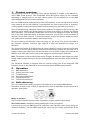
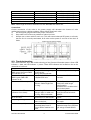
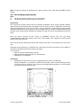
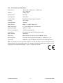
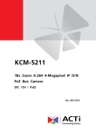
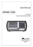
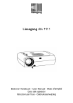
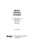
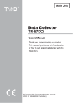
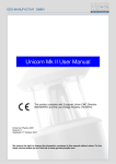
Chroma-Q™
Cascade™
User Manual
Version 1.2 December 2006
PN: 109-0500
Disclaimer
The information contained herein is offered in good faith and is believed to be accurate.
However, because conditions and methods of use of our products are beyond our control, this
information should not be used in substitution for customer's tests to ensure that Chroma-Q
products are safe, effective, and fully satisfactory for the intended end use. Suggestions of use
shall not be taken as inducements to infringe any patent. Chroma-Q sole warranty is that the
product will meet the sales specifications in effect at the time of shipment. Your exclusive
remedy for breach of such warranty is limited to refund of purchase price or replacement of any
product shown to be other than as warranted.
Chroma-Q reserves the right to change or make alteration to devices and their functionality
without notice due to our on going research and development.
The Chroma-Q Cascade has been designed specifically for the professional entertainment
lighting industry. Regular maintenance should be performed to ensure that the products
perform well in the entertainment environment.
If you experience any difficulties with any Chroma-Q products please contact your selling
dealer. If your selling dealer is unable to help please contact [email protected]. If the
selling dealer is unable to satisfy your servicing needs, please contact the following, for full
factory service:
Outside North America:
Tel: +44 (0)1494 446000
Fax: +44 (0)1494 461024
[email protected]
North America:
Tel: 416-255-9494
Fax: 416-255-3514
[email protected]
For further information please visit the Chroma-Q website at www.chroma-q.com.
Chroma-Q is a trademark, for more information on this visit www.chroma-q.com/trademarks.
The rights and ownership of all trademarks are recognised.
Cascade User Manual
1
V1.2 December 2006
Table of Contents
1.
Product Overview ……………………..………………………….………................ 3
2.
Operation ……………...…………………………………………………….…….….. 3
2.1
DMX addressing ………………………………………………………………. 3
2.2
Control and power cables ……………………………..……………….…… 4
2.3
Troubleshooting …..…………………………………………………………... 5
2.4
Gel loading / replacement ……………………………………………..…… 6
2.5
Technical overview ………………………………………………………...... 8
2.6
Technical specifications ……………………………………………………... 9
3.
Charts …………………………………………………………………………………. 10
3.1
Colour chart (Library mode) ……………………………………………….. 10
3.2
Colour chart (Creative mode) ……………………………………………... 10
Cascade User Manual
2
V1.2 December 2006
1.
Product overview
The Chroma-Q Cascade is a scrolling colour changer designed to operate on the ANSI E1.11
USITT DMX 512-A protocol. This multiplexed serial data system allows for the individual
addressing of multiple units on one data cabling system. The unit utilises one or two DMX
channels depending on the mode of operation.
The unit is addressed by setting the three rotary BCD switches, on the rear panel. Next to these
rotary switches are four DIP switches. These switches are used to select mode of operation,
scrolling speed, & cooling fan speed. (Details of these settings are given later in section 3.1)
The unit operates using subtractive colour mixing method. This method relies on having a full
spectrum source (white light) & then filtering out some of the colours to achieve the desired
hue & saturation. The secondary (subtractive) colours are Cyan, Magenta & Yellow. By mixing
two of the basic subtractive filters at different saturations, you are able to mix hundreds of
different colours within one unit. To further the creative process, the primary (additive) colours
(red, green & blue) have been added to the back gel string.
This unit combines the secondary colours by using two gel strings. The choice was made to
get maximum reliability, maximum light output & to keep the dimensions & weight to a
minimum.
The Chroma-Q Cascade is supplied power & control signals by means of two 4-pin XLR style
connectors on the rear panel, allowing multiple units to be daisy-chained into the same line of
cabling. Patching the output from the last unit back into the power supply will terminate the
DMX for each chain line & ensure even power voltage across all scrollers in that chain.
Note: The quantity of Chroma-Q Cascade colour changers, & maximum cable length per power
supply output is dependant upon the size of PSU/splitterbox used (see later in this manual for
details).
The Chroma-Q Cascade is equipped with two internal cooling fans & two diagnostic LED
indicators (found on the underside of the unit) showing Power & DMX signal presence.
2.
2.1
2.2
2.3
2.4
2.5
2.6
Operation
DMX addressing
Control and power cables
Troubleshooting
Gel loading/replacement
Technical overview
Technical specifications
2.1 DMX addressing
The unit is addressed by setting the three rotary switches to the required DMX address.
Remember to allow for the number of channels used, which is dependant on the units mode of
operation. (See below)
Modes of operation
The Chroma-Q Cascade has two modes of operation, Creative mode & Library mode.
The Creative mode is enabled by setting dipswitch #1 to the "off" position.
In this mode you use one DMX channel to control the each individual colour string, giving you
maximum flexibility. The first DMX channel will control the front string (Yellow-Cyan) & the
Cascade User Manual
3
V1.2 December 2006
second DMX channel controls the back string (Yellow-Magenta). You can speed up the
movement of the scrollers by turning dipswitch #2 on in this mode.
The Library mode is design to give you quick access to a 100 pre-programmed colours.
Turning on the dipswitch #1 "on" will give you access the Library mode. This is achieved by
entering a percentage value in the console (from 0% to 100%). You can refer to the chart
(section 5.1) to find which percentage matches with which colour. In this mode dipswitch #2
will select between fixed speed between colours when it is in the "off" position, or variable
speed controlled by the next DMX channel if it is in the "on" position.
SW1
SW2
SW3
SW4
OFF
OFF
OFF
ON
X
X
X
X
Mode
Creative
Regular gel speed
High gel speed
ON
ON
OFF
ON
X
X
X
X
Library
Fixed gel speed
Controlled gel speed
X
X
X
X
X
X
X
X
OFF
ON
OFF
ON
OFF
OFF
ON
ON
DMX Channels
2
2
2
1 or 2
1
2
Fan Speed
High fan speed
Medium fan speed
Medium fan speed
Low fan speed
Note:
a)
Do not power lights without powering up the scroller first. Fan must be running in order
to protect gels from premature failure.
b)
High fan speed is recommended on all lighting fixtures of 750 Watts & above.
c)
Use of a high quality IR filter medium on ellipsoidal lighting fixtures is strongly
recommended, especially those with beam angles of less than 30 degrees.
2.2 Control and power cables
The Chroma-Q Cascade utilises an XLR 4-pin cable system. This is used for power & data
transfer. Pins 2 & 3 are for ANSI E1.11 USITT DMX 512-A data. Pins 1 & 4 are for 24VDC power.
Note: It is very important to ensure that the drain wire from the cable shield is connected to
both XLR connector cases. When assembling XLR 4-pin cables, heat shrink should be used on
each individual pin to prevent short circuits.
Damage will occur if power connections short to data connections (see below).
Detail of connector wiring
The correct wiring between male & female connectors is 'one to one'.
Cascade User Manual
4
V1.2 December 2006
Pin #
1
2
3
4
Chassis
Pin #
Ground (-ve)
Control data minus (-)
Control data plus (+)
24V DC (+ve)
Cable shield/drain wire
Minimum Cable size
2.00mm² (14 AWG)
0.35mm² (22 AWG)
0.35mm² (22 AWG)
2.00mm² (14 AWG)
0.25mm² (24 AWG)
Note: Cable length should not exceed more than 60m/200' with return line.
Connections
Correct connection of the units to the power supply will decrease the chances of units
malfunctioning due to cabling problems. Please follow these basic rules.
a)
Use the type & gauge of cable with proper connectors.
b)
Keep cable runs as short as possible to reduce line loss.
c)
Always use a return cable for each run. This will ensure balanced DC power to all units,
that the line is correctly terminated, & all units receive power if one link of the chain is
faulty.
2.3 Troubleshooting
The 2 LED indicators aid in the trouble shooting of the Chroma-Q Cascade system. Green LED
indicator = data, red LED indicator = power. These LED indicators are located on the on the
underside of each unit.
Symptom
Possible Cause
Solution
Unit does not respond to
Rotary switch settings may
Check rotary switch settings.
DMX control, but green DMX
not be correct.
LED indicator is on.
Wrong address selected.
Unit does not respond to
Bad cable. No DMX present
Check cable & DMX run from
DMX & green DMX LED
at Splitter/PSU unit.
console.
indicator is off.
Units run at different speeds.
Dipswitch settings may be
Check dipswitch settings.
different. Cable lengths are
Check the cable length
too long.
configuration.
Ensure there is a cable return
line in the system.
Units have dim LED
Overloading of colour
Check voltage levels on last
indicators & run slowly
changer chain or cable runs
unit. Should not be below
too long. PSU overloaded.
20VDC.
Green DMX LED indicator is
Bad cable or blown
Check cable or send unit for
off on one unit.
transceiver IC in the scroller.
repair.
Only one gel string runs.
Mechanical (or electrical)
Turn unit on & off. Return unit
failure in the unit.
for repair.
Gel burns too quickly.
Fans have failed. Poorly
Check fans are operating.
optimised lamp focus in
Optimise lamp focus. Replace
fixture. IR filter medium not
gel strings & install IR filter.
fitted.
Cascade User Manual
5
V1.2 December 2006
Note: A high percentage of problems are a direct result of poor cable & corrupt DMX control
signals.
2.4 Gel loading/replacement
Note:
a)
See also the drawing section (4.1) of this manual.
b)
The power does not have to be on to load gels.
Introduction
The Chroma-Q Cascade comes with two specially graduated colour strings already installed.
Should these gel strings become damaged or worn out they must be replaced to ensure the
optimum performance of the colour scroller. The gel material is a proprietary design long-life
substrate. Replacement gel strings may be purchased from your dealer. Substitute gels strings
should not be used as these will effect the operation of the unit & may cause damage to the unit
itself.
Each gel string consists of two series of graduated colours. The rear gel string
(yellow/magenta) starts with yellow, then clear in the middle, then magenta at the end (plus
primary red, green, & blue).
The front gel string (yellow/cyan) starts with yellow, then clear in the middle, then cyan at the
end.
Changing the gel strings is not difficult, but it may take some time & practice to accomplish, if
the user is not familiar with these types of scrollers.
You will need:
1 x Set of Chroma-Q Cascade gel strings
1 x Roll of flat back adhesive tape (i.e. 'Artists' tape)
1 x Phillips No.1 screwdriver
Preparation
1.
Unplug the unit & remove it from the lighting fixture to which it is attached.
Using a Phillips No. 1 screwdriver, remove the four M3 × 4mm screws holding the front
cover onto the unit. Place the unit, with the mounting plate facing down, on a flat surface
& carefully remove the front cover.
Cascade User Manual
6
V1.2 December 2006
2.
Remove all the pieces of the old gel strings. This may involve unwinding the gels from
the Take-Up Reels (TUR). Exercise caution to avoid damaging the gel transport
mechanism.
Replacing the rear gel string (yellow/magenta)
Note: See the drawing section of this manual.
1.
Place the unit on a flat surface with the motor/fan/electronics section on your right-hand
side. Take the yellow/magenta gel string & attach the gel tab (on the yellow end) to the
hook on the TUR (Take-Up Reel) anchor of the rear fixed shaft.
2.
Use a small piece of flat back tape 25 x 25mm (1" x 1") to secure each side of the gel to
the TUR hubs on either side.
3.
Manually turn the fixed gear of the shaft to slowly roll the gel string onto the TUR.
Continue rolling the gel onto the TUR until the other end is reached.
4.
Firmly holding the gear of the rear fixed shaft to stop it moving, gently pull the gel tab
towards you. This ensures that the gel is tightly on the TUR.
5.
Rotate whole the unit so that the motor/fan/electronics section on your left hand side.
Place the gel tab beside the anchor on the rear spring shaft.
6.
With your left hand, firmly hold the gel tab next to the anchor hook (do not attach it yet).
With your right hand, turn the anchor hub of the spring shaft towards you counterclockwise for five complete turns (as you turn the shaft you should feel the spring
tension increasing).
7.
After tensioning, hold the anchor steady & hook the gel tab onto the anchor.
8.
Use a small piece of flat back tape 25 x 25mm (1" x 1") to secure each side of the gel to
the TUR hubs on either side.
9.
Manually roll some of the gel string onto the spring TUR to check it is seating itself
properly.
Replacing the front gel string (yellow/cyan)
1.
Place the unit on a flat surface with the motor/fan/electronics section on your left-hand
side. Take the yellow/cyan gel string & attach the gel tab (on the yellow end) to the hook
on the TUR anchor of the front fixed shaft.
2.
Use a small piece of flat back tape 25 x 25mm (1" x 1") to secure each side of the gel to
the TUR hubs on either side.
3.
Manually turn the fixed gear of the shaft to slowly roll the gel string onto the TUR.
Continue rolling the gel onto the TUR until the other end is reached.
4.
Firmly holding the gear of the front fixed shaft to stop it moving, gently pull the gel tab
towards you. This ensures that the gel is tightly on the TUR.
5.
Rotate whole the unit so that the motor/fan/electronics section on your right hand side.
Place the gel tab beside the anchor on the rear spring shaft.
6.
With your left hand, firmly hold the gel tab next to the anchor hook (do not attach it yet).
With your right hand, turn the anchor hub of the spring shaft towards you counterclockwise for five complete turns (as you turn the shaft you should feel the spring
tension increasing).
7.
After tensioning, hold the anchor steady & hook the gel tab onto the anchor.
8.
Use a small piece of flat back tape 25 x 25mm (1" x 1") to secure each side of the gel to
the TUR hubs on either side.
Cascade User Manual
7
V1.2 December 2006
9.
Manually roll some of the gel string onto the spring TUR to check it is seating itself
properly.
Completion and testing
1.
Plug in the scroller and check that it goes through the initialisation sequence correctly.
Check that the gels run smoothly and do not bind up on the TUR's.
2.
Unplug the unit, replace the front cover and secure with the M3 screws.
3.
Run a test sequence to allow the gel strings to bed-in. The unit does not have to be
attached to a lighting fixture to perform this operation. This sequence can either be
programmed on your control desk, or you can use the unit's inbuilt test sequence by
setting the address switches to 601. It is recommended that you run this sequence for 10
minutes or 4 times end-to-end.
Note: The number of turns may vary slightly between take up reel spools due to tolerances in
the tension spring, however no more than five turns should be required to tension gel string.
Note: Poorly optimsed lamps in lighting fixtures may result in premature gel failure.
2.5 Technical overview
The Chroma-Q Cascade unit is essentially two scrollers in one package. The colour mixing
system employs an opto-electronic system for accurate positioning of the gel. When the unit
initially receives power, it will go through a calibration sequence. The purpose of the initial
calibration sequence during power up is to determine the total length of the gel string, and
therefore the position of the different gels.
Note: Over time the gel string may warp slightly. This may alter the positions of the gels
relative to their pre-programmed DMX values and therefore some fine-tuning may be required.
The motors have an optical encoder feedback system. The purpose of which is to convert
motor revolutions in to electronic pulses, and also to determine which direction the motor is
turning.
The electronic cards consist of three key components: L298 motor driver, 75176 Transceiver
and a Processor. The L298 is a true digital device receiving two PWM signals to operate speed
and direction. The 75176 transceiver operates in the receive configuration to convert serial
protocol to a TTL level. The processor is an OTP part containing proprietary software.
The majority of electronics problems are usually created by external factors such as shorted
cables, etc. The 75176 transceivers are susceptible to damage if 24VDC is present on the DMX
signal lines.
Routine maintenance can prevent most mechanically based problems. The motor mounting
plate can be adjusted to control tension on the belt. Excessive belt tension is often the cause of
noise and poor performance. Conversely, loose motor belts can cause accuracy problems.
Troubleshooting is a process of elimination. First, rule out the other field factors (i.e. faulty
cables, power sources). If an electronics problem is suspected try replacing the electronics card
first. If accuracy problems should occur and mechanical problems have been ruled out, replace
optical sensors. For technical advice and/or parts, please contact your selling dealer or the
offices listed in this manual.
Cascade User Manual
8
V1.2 December 2006
2.6
Technical specifications
Dimensions:
306mm (w) × 340mm (h) × 100mm (d)
12" × 13.5" × 4"
Weight:
2.56kg/5.63lb
Rear aperture:
178mm/7"
Front aperture:
241mm/9.5"
Colour media:
Proprietary design long life substrate
Cooling:
2 fan design
Cooling Speed:
4 speeds
DMX protocol:
ANSI E1.11 USITT DMX 512-A
DMX addressing:
3 × rotary BCD switch (512 channels)
Working Voltage:
24VDC (+/- 10%)
Power consumption:
1.5 PU (see note below)
Connectors:
XLR-4 (male) in and XLR-4 (female) through
Body material:
Aluminium
Body color:
Black powder coat (other colours available, P.O.A.)
Mounting plate:
Universal mounting system fits 160mm × 254mm/6¼" x 10"
Approvals:
EN55103-1 and 2, IEC 60950, FCC Part 15 and ICES-003 Class A
Note: To simplify the choice of power supply we use the "PU" (Power Unit) to calculate the load
requirements of the Chroma-Q system. For example a PS-08 will supply up to 8 PU's, so you
can plug-in 5 Chroma-Q Cascade (5 × 1.5PU = 7.5PU) into a PS-08.
Cascade User Manual
9
V1.2 December 2006
3.
Charts
3.1 Library mode
3.2 Creative mode
Cascade User Manual
10
V1.2 December 2006