1
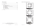
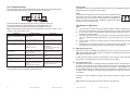
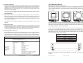
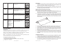
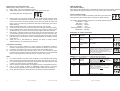
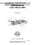
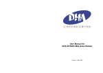
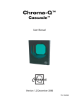
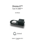
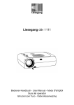
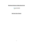
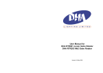
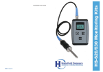
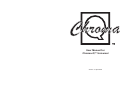
User Manual for
Chroma-Q™ Universal
Version 1.0 April 2003
Table of Contents
Examples of Mounting Bracket Positions
(1)
Page
Product overview ...........................................................................................2
(2)
Product description .......................................................................................2
(3)
Operation .......................................................................................................3
(3.1) Control and power cables ..................................................................3
(3.2) Operating the unit ..............................................................................5
(3.3) Modes of operation (inc. DMX addressing) .......................................6
(3.4) Gel loading ........................................................................................9
(3.5) Mounting the unit .............................................................................12
(3.6) Troubleshooting ...............................................................................13
(3.7) Technical overview ..........................................................................14
(3.8) Technical specifications ...................................................................15
(4)
Drawings .....................................................................................................16
Chroma-Q is a trademark of A.C. Lighting Ltd.
The information contained herein is correct at the time of going to press, however as we are constantly refining our product
range we reserve the right to change the specification without notice.
The rights and ownerhip of all trademarks are recognised.
1
Version 1.0 April 2003
Chroma-Q™ Universal
Chroma-Q™ Universal
Version 1.0 April 2003
18
(1) Product Overview
Gel string dimensions
The Chroma-Q™ Universal is designed to give years of trouble free use, providing
that it is regularly maintained and is used in accordance with the instructions detailed
in this manual. If you should experience any problems that fall outside of the scope
of this manual, please contact the selling dealer for further details.
If the selling dealer is unable to satisfy your servicing needs, please contact the
following, for full factory service:
Outside North America:
A.C. Lighting Ltd.
Centauri House,
Hillbottom Road, High Wycombe,
Buckinghamshire, HP12 4HQ.
United Kingdom
Tel: +44(0) 1494 446000
Fax: +44(0) 1494 461024
[email protected]
www.aclighting.com
North America:
A.C. Lighting (Canada) Ltd.
Unit #1, 435 Horner Avenue,
Toronto, ON.
M8W 4W3
Canada
Tel: +1 416-255-9494
Fax: +1 416-255-3514
[email protected]
www.aclighting.com
(2) Product Description
The Chroma-Q™ Universal is a scrolling colour changer designed to operate on the
USITT DMX512 (1990) protocol. This multiplexed serial data system allows for the
individual addressing of multiple units on one data cabling system. The unit utilises
one or two DMX channels depending on the mode of operation.
The unit is addressed by using the three push button switches and LED display on
the rear panel. These switches are also used to select mode of operation, scrolling
speed and cooling fan speed.
The Chroma-Q™ Universal is supplied power and control signals by means of two
4-pin XLR style connectors on the rear panel, allowing multiple units to be 'daisychained' into the same line of cabling. Patching the output from the last unit back into
the power supply will terminate the DMX for each chain line and ensure even power
voltage across all scrollers in that chain.
Note: The quantity of Chroma-Q™ Universal colour changers, and maximum cable
length per power supply output is dependant upon the size of PSU/splitterbox used
(see later in this manual for details).
The rear of the unit incorporates an integral universal mounting bracket, which allows
the unit to be easily configured to fit on fixtures from 160-275mm (6¼"-10¾") frame
size.
The Chroma-Q™ Universal is equipped with two internal cooling fans and a
diagnostic section on the LED display showing power, DMX signal and level
presence.
17
Version 1.0 April 2003
Chroma-Q™ Universal
Chroma-Q™ Universal
Version 1.0 April 2003
2
(3) Operation
(4) Drawings
(3.1)
(3.2)
(3.3)
(3.4)
(3.5)
(3.6)
(3.7)
(3.8)
Outside dimensions of the Unit.
Control and power cables
Operating the unit
Modes of operation (inc. DMX addressing)
Gel loading
Mounting the unit
Troubleshooting
Technical overview
Technical specifications
(3.1) Control and power cables
The Chroma-Q™ Universal utilises an XLR 4-pin cable system. This is used for
power and data transfer. Pins 2 and 3 are for DMX (USITT 1990) data. Pins 1 and 4
are for 24VDC power.
Damage will occur if power connections short to data or ground/shield connections.
When assembling XLR 4-pin cables, heat shrink should be used on each individual
pin to prevent short circuits (see diagram below).
Note: It is very important to ensure that the drain wire from the cable shield is
connected to both XLR connector cases.
Detail of connector wiring
The correct wiring between male and female connectors is 'one to one'.
3
Version 1.0 April 2003
Chroma-Q™ Universal
Chroma-Q™ Universal
Version 1.0 April 2003
16
(3.8) Technical specifications:
Dimensions:
345mm (w) × 360mm (h) × 85mm (d)
13.6" × 14.1" × 3.4" inc. mounting brackets
Weight:
2.5kg/5.5 lb inc. gel string & mounting brackets
Rear aperture:
203mm/8"
Front aperture:
260mm/10.25"
Colour Media:
Most commercially available gel media
Gel capacity:
2-24 gels
Cooling:
2 fan design
Cooling speed:
Multiple speeds
Addressing:
Digitally via 3 push buttons and LED display
Working voltage:
24 VDC (+/- 10%)
Power consumption:
1.5PU (see note below)
Protocol:
USITT DMX512 (1990)
Body material:
Aluminium
Unit Colour:
Black powder coat (other colours available, P.O.A.)
Mounting Plate:
Universal mounting system fits 160-275mm
(6¼"-10¾") fixtures
Connectors:
XLR-4 (male) in and XLR-4 (female) through
European approvals:
Pending
North American approvals: Pending
Pin #
1
2
3
4
Chassis
Pin #
Ground (-ve)
Control data minus (-)
Control data plus (+)
24VDC (+ve)
Cable shield/drain wire
Minimum Cable Size
2.50mm² (14 AWG)
0.35mm² (22 AWG)
0.35mm² (22 AWG)
2.50mm² (14 AWG)
0.25mm² (24 AWG)
Note: Cable length should not exceed more than 75m (250') with return line.
Connections
Correct connection of the units to the power supply will decrease the chances of
units malfunctioning due to cabling problems. Please follow these basic rules.
a) Use the correct type and gauge of cable and connectors.
b) Keep cable runs as short as possible to reduce line loss.
c)
Always use a return cable for each run. This will ensure balanced DC power to
all units, that the line is correctly terminated, and all units receive power if one
link of the chain is faulty.
Note: To simplify the choice of power supply we use the "PU" (Power Unit) to
calculate the load requirements of the Chroma-Q™ system. For example a PS-08
will supply up to 8 PU's, so you can plug-in 5 Chroma-Q™ Universals (5 x 1.5PU =
7.5PU) into a PS-08.
15
Version 1.0 April 2003
Chroma-Q™ Universal
Chroma-Q™ Universal
Version 1.0 April 2003
4
(3.2) Operating the unit
(3.7) Technical overview
All the unit functions are accessed using the LED display and the three push-button
switches on the rear panel.
The colour transport system employs an opto-electronic system for accurate
positioning of the gel. When the unit initially receives power it will go through a
calibration sequence. The purpose of the initial calibration sequence during power
up is to determine the total length of the gel string and therefore the position of the
different gels.
Note: Over time the gel string may warp slightly. This may alter the positions of the
gels relative to their pre-programmed DMX values and therefore some 'fine-tuning'
may be required.
Control
Red Button
Black Button
Brown Button
3 digit display
The motors have an optical encoder feedback system. The purpose of this is to
convert motor revolutions in to electronic pulses, and also to determine which
direction the motor is turning.
Function
Mode access and record
Decreases (-) the mode level or value
Increases (+) the mode level or value
Displays mode, monitor or blank disply
Push button operation:
The red button is used to scroll through the different modes of operation. The brown
or black buttons are used to select the level or value in that mode. If any mode or
value is changed, the display will flash until the red button is pushed to save the
change.
Display operation:
Power-up display
On power-up, the unit will go through its self-calibration mode and
the display will show the units software version.
The electronic cards consist of three key components: L298 motor driver, 75176
Transceiver and a processor. The L298 is a true digital device receiving two PWM
signals to operate speed and direction. The 75176 transceiver operates in the
receive configuration to convert serial protocol to a TTL level. All data relevant to the
operation of the unit is stored onboard in 'flash' memory.
The majority of electronics problems are usually created by external factors such as
shorted cables, etc. The 75176 transceivers are susceptible to damage if 24VDC is
present on the DMX signal lines.
Routine maintenance can prevent most mechanically based problems. The motor
mounting plate can be adjusted to control tension on the belt. Excessive belt tension
is often the cause of noise and poor performance. Conversely, loose motor belts can
cause accuracy problems.
After the self-calibration finishes, the display will show the DMX
address.
Monitor display
If left undisturbed for 5-7 seconds, the display will revert to 'Monitor Mode'
Troubleshooting is a process of elimination. First, rule out the other field factors (i.e.
faulty cables, power sources). If an electronics problem is suspected try replacing
the electronics card first. If accuracy problems should occur and mechanical
problems have been ruled out, replace optical sensors. For technical advice and/ or
parts, please contact your selling dealer or the offices listed in this manual.
The first vertical bar indicates that there is power (24VDC) at the unit.
The second vertical bar indicates that there is data (DMX) at the unit.
The horizontal bars indicate the data (DMX) signal level at the unit.
(See also: 'Troubleshooting' section of this manual)
Display flip
The display can be flipped through 180º by pressing and holding the red button, then
pressing the black button.
5
Version 1.0 April 2003
Chroma-Q™ Universal
Chroma-Q™ Universal
Version 1.0 April 2003
14
(3.6) Troubleshooting
The LED display aids in the troubleshooting of the Chroma-Q™ Universal system.
These indicators are located on the on the rear panel of each unit.
Display blank
The display can be set to auto-blackout after short time. This is selected through the
Display mode menu (see later in this section).
Reset
If the red button is held down and the brown button pressed, the unit
will reset to the factory default settings. This feature is particularly
useful when the units are used in many different configurations or
shows. The reset function is also available via DMX (see remote
operation section of this manual).
The first vertical bar indicates that there is power (24V DC) at the unit.
The second vertical bar indicates that there is data (DMX) at the unit.
The horizontal bars indicate the data signal level (DMX) at the unit.
Note: The signal level changes during normal operation of the unit. 1st bar = 25%,
2nd bar = 50% and 3rd bar = 75%
SYMPTOM
POSSIBLE CAUSE
SOLUTION
Unit does not respond to DMX
control, but DMX display indicator
is on.
Unit set to a wrong or different
DMX address.
Check DMX address settings.
Unit does not respond to DMX,
DMX display indicator is off.
Bad cable. No DMX present at
Splitter/PSU unit.
Check cable and DMX run from
console.
Units run at different speeds.
Scroller speed settings may be
different. Cable lengths are too
long.
No cable return line.
Check all scroller speed settings.
Check the cable length and
configuration.
Ensure there is a cable return
line in the system.
Units have dim display indicators
and run slowly.
Over loading of colour changer
chain or cable runs too long.
PSU overloaded.
Check voltage levels on last unit.
Should not be below 20VDC.
DMX display indicator is off on
one unit.
Bad cable or blown transceiver
IC in the scroller.
Check cable or send unit for
repair.
Display indicators appear OK but
gel string does not move.
Mechanical (or electrical) failure
in the unit.
Turn unit on and off. Return unit
for repair.
Gel burns too quickly.
Fans have failed or are too slow.
Poorly optimised lamp focus in
fixture.
IR filter medium not fitted.
Check fans are operating.
Optimise bulb focus. Replace gel
strings & install IR filter.
Note: A high percentage of problems are a direct result of poor cable, corrupt DMX
control signals and lack of suitable signal termination.
(3.3) Modes of Operation
Note:
a) The red button is used to scroll through the different modes of operation and
the brown or black buttons are used to select the level or value in that mode.
b) If any mode or value is changed the display will flash until the red button is
pushed to save the change.
c)
When the red record button is pressed, the unit will save the change and these
new User defaults will take precedence on the next power cycle or remote
reset.
d) The unit will not save any change made by remote operation after the next
power cycle.
e) Resetting the unit will return all of the user settings to factory defaults. Press
and hold the red and brown buttons at the same time to reset the unit.
³ DMX addressing mode
This mode is used to set DMX data address of the unit. The unit uses one or two
DMX channels depending which mode it is operating. The display shows the current
DMX address (between 1-512).
To alter the value, press the brown or black button once to step the value; hold down
the buttons for fast adjustment. Press red to save the new setting.
³ Fan speed mode (Fn)
Fan speed mode is used to set the gel cooling-fan speed of the unit. This feature can
be used in environments where a lower noise level is required. The display shows
the current gel cooling fan speed. There are four fan speeds, 1 is the slowest and 4
the fastest (the default is 4). To alter the value, press the brown or black button once
to step the value; hold down the buttons for fast adjustment. Press red to save the
new setting.
This feature is also available via DMX (see "Remote operation" section of this
manual).
Note: reducing the fan speed may reduce the life of the gel string.
13
Version 1.0 April 2003
Chroma-Q™ Universal
Chroma-Q™ Universal
Version 1.0 April 2003
6
³ Gel saver mode (GL)
Gel-saver mode is used to switch the gel-saving mode on or off. This feature slowly
moves the chosen gel frame back and forward slightly so that the heat build-up is
dissipated over a larger area, extending the life of the gel string. Press the brown or
black buttons once to switch between On (1) and Off (0) (the default is Off). Press
red to save the new setting.
(3.5) Mounting the unit
Note: See drawing section of this manual.
The Chroma-Q™ Universal is designed for mounting in an upright position with the
base of the unit below the fixture. Do not mount in an inverted position with the base
of the unit above the fixture, as the rising heat from the fixture may cause the gel
string damage.
This feature is also available via DMX (see "Remote operation" section of this manual).
³ Speed mode (SP)
Speed mode is used to set the maximum scrolling speed of the unit. This feature
allows the gel string to move at a higher speed for more rapid changes. Use of the
high speed will generate more noise from the unit. Press the brown or black buttons
once to switch between Standard (1) and Fast (2) (the default is Standard). Press red
to save the new setting.
This feature is also available via DMX (see "Remote operation" section of this
manual).
³ Display mode (dP)
This mode is used to switch the default display On or Off. This feature can be used
to blank the display when in normal use. However the display will re-activate when
any button is pressed. Press the brown or black buttons once to switch between On
(1) and Off (0) (the default is On). Press red to save the new setting.
³ Remote operation mode (ro)
Remote operation mode is used to select between the 3 control modes. The use of
these different modes greatly enhances the versatility of the unit by giving the user
remote control of the most of the functions. Press the brown or black buttons to
switch between the modes (the default is Mode 1). Press red to save the new setting.
Mode 1 =
Single channel DMX operation. The channel controls the colour selection.
Mode 2 =
Dual channel DMX operation. The 1st channel controls the colour selection. The
2nd channel controls the fan speeds:
0-24% = Fn 4 (fast), 25-39% = Fn 3, 50-74% = Fn2, 75-100% = Fn 1 (slow)
Mode 3 =
Dual channel DMX operation. The 1st channel controls the colour selection. The
2nd channel controls the units other functions.
Channel 2 level
Feature
0-5%
= No feature
6-15%
= Fan off
16-25%
= Fan speed 1 (slowest)
26-35%
= Fan speed 2
36-45%
= Fan speed 3
46-55%
= Fan speed 4 (fastest)
56-65%
= Gel Saver off
66-75%
= Gel Saver on
76-85%
= Motor speed normal, see Speed mode (SP)
86-95%
= Motor speed fast, see Speed mode (SP)
96-100%
= Reset (reset to user defaults)
These functions
initialise two
seconds after the
channel level
entered.
7
Version 1.0 April 2003
Chroma-Q™ Universal
The rear of the unit incorporates an integral universal mounting system, which allows
the unit to be easily configured to fit on fixtures from 158mm (6¼") to 275mm (10¾")
frame size. This system consists of four brackets, held by eight screws, fixed to eight
(of possible sixteen) mounting stand-off fixings.
To alter the mounting brackets, simply loosen the two screws on each bracket, move
the bracket to the required position and re-tighten the screws. The brackets have a
combination of letters & numbers stamped on them so that you can record the
particular sizes you use. Some examples of these bracket positions are given below
and in the drawing section of this manual:
Bracket
Position
Standoff
Position
Light Fixture
3
A
C
B
A
1
Inside
Inside
Outside
Outside
Outside
Outside
Source 4™
Source 4 PAR™
Euro 215mm
Silhouette™ 2K
Variour PAR 64
Strand™ 2K
C
3
B
A
2
1
Note: The Chroma-Q™ Universal should always be used with the safety wire
provided.
Chroma-Q™ Universal
Version 1.0 April 2003
12
Replacing the gel string (EZ-Load)
Note: See the drawing section of this manual.
1) Follow steps 1+2 in the preparation section.
2) While pressing down the red push button, apply power to the unit.
The display will show the legend PAL
3)
4)
5)
6)
7)
8)
9)
Using 25mm (1") long pieces of tape attach the leading edge of the gel string
to the plastic TUR at the top and bottom of the string, ensuring that the gel is
centred on the TUR. Move the gel string to the side and attach the other side
string to the TUR with tape (a black line has been scribed along the TUR to
assist with this).
Press the black push button to advance the gel string onto the TUR.
Continue this process until you see the other end of the gel string approaching.
Firmly holding the gear of the rear fixed shaft (to stop it moving), gently pull the
gel tab towards you. This ensures that the gel is tightly rolled onto the TUR.
Use 25mm (1") pieces of tape to secure the gel to the TUR top and bottom, and
on both sides (a black line has been scribed along the TUR to assist with this).
Press the brown push button to move the gel string back onto the TUR. Use the
push buttons to move the gel to and fro, checking that the gel is sitting correctly
on the TUR's.
Allow the unit to self-calibrate by pressing the brown & black buttons
simultaneously or by cycling power to the unit.
Completion and testing
1) Plug in the unit and check that it goes through the initialisation sequence
correctly. Check that the gel runs smoothly and does not bind up on the TUR's.
2) Unplug the unit, replace the front cover and secure with the M3 screws.
3) Run a test sequence to allow the gel string to 'bed' in. The unit does not have
to be attached to a lighting fixture to perform this operation. It is recommended
that run this sequence for a few minutes (or 3/4 times, end-to-end).
Note:
a) For normal operation, the start of the gel string is on the left-side TUR and the
end of the string on the right-side TUR, when viewed from the front of the unit.
b) Do not power lights without powering up the unit first. The fans must be running
in order to protect gels from premature failure.
c)
High fan speed is recommended on all lighting fixtures of 750 Watts and above.
d) Use of a high quality IR filter on ellipsoidal lighting fixtures is strongly
recommended, especially those with beam angles of less than 30 degrees.
e) Poorly optimised lamps in some fixtures may result in premature gel failure.
Default Settings
User default settings
Each time the red record button is pressed, the unit will save that change and these
User defaults will take precedence on the next power cycle or remote reset.
Factory default settings
If the unit is reset, using the red button (held down) and the brown
button pressed, the unit will reset to the Factory default settings.
The Factory default settings put the unit in its safest operating mode.
Fan speed = 4 (fast)
Gel saver = 0 (off)
Gel speed = 1 (slow)
Display = 1 (on)
Remote operation = 1 (normal)
Display flip = standard
Summary of control functions
Operation
or mode
Operation
description
Actions required
Power-Up
Software version shown on the unit at
power-up.
This shows the software version while the unit
is self-calibrating, befor displaying the ‘Monitor
Mode’.
rESet
This will reset the
unit to the default
settings.
While holding down the red button, press the
brown button.
Power Assisted
Loading
(EZ Load)
Used to load a gel
string into the unit.
Hold down the red button during power-up.
Pressing the black button will advance the gel
in that direction. Pressing the brown button will
advance the gel in the opposite direction.
Press both brown and black buttons, or cycle
the power, to recalibrate.
Display
Modes (use the red button to scroll through these modes)
The display shows DMX address (1-512).
Press brown or black once to increment/
decrement the value, hold down the brown or
black for fast advance/retreat.
Press red to save the new setting.
DMX
addressing
mode
Used to set the
units DMX
addresses
Fan speed
Mode
Used to set the fan
speed of the unit.
The display shows the current gel cooling fan
speed. There are four fan speeds, 1 is the
slowest, 4 is the fastest.
Press brown or black once to increment/
decrement the value.
Press red to save the new setting.
11
Version 1.0 April 2003
Chroma-Q™ Universal
Chroma-Q™ Universal
Version 1.0 April 2003
8
‘GeL Saver’
Mode
Switches on/off the
gel saving mode.
The display shows the current gel saver mode.
Press brown or black once to switch between
on (1) and off (0).
Preparation
1)
2)
Press red to save the new setting.
‘SPeed’
Mode
Used to set the
scrolling speed of
the unit.
The display shows the current gel scrolling
speed. There are two scrolling speeds. 1 is the
slowest, 2 is the fastest.
Press black or brown once to increment/
decrement the value.
Press red to save the new setting.
‘disPlay’
Mode
Switches on/off the
display.
‘remote
operation’
Mode 1 = single
DMX channel
operation.
Mode 2 = Dual
DMX channel
operation
(Colour/Fan speed)
Mode 3 = Dual
DMX channel
operation
(Colour/Function)
Switches on/off the display. Display will
re-activate when any button is pressed. Press
brown or black to switch between on (1) and
off (0).
Unplug the unit and remove it from the lighting fixture to which it is attached.
Using the screwdriver, remove the four M3 x 4mm screws holding the front
cover onto the unit and carefully remove the front cover.
Remove all pieces of the old gel string if necessary. This may involve
unwinding the gel from the Take-Up Reels (TUR). Exercise caution to avoid
damaging the gel transport mechanism.
Replacing the gel string (manual mode)
Note: See also the drawing section of this manual.
1) Place the unit on a flat surface with the motor/fan/electronics section on your
right-hand side (assuming you are loading the gel string from the 'tail' end,
reverse the position if starting with the 'leader' end of the string).
2) Using 25mm (1") long pieces of tape, attach the leading edge of the gel string
to the plastic TUR at the top and bottom of the string, ensuring that the gel is
centred on the TUR. Move the gel string to the side and attach the other side
string to the TUR with tape (a black line has been scribed along the TUR to
assist with this).
Press red to save the new setting.
The display shows the current DMX mode of
the unit. There are three DMX modes
Press brown or black button to increment/
decrement the mode setting.
3)
Press red to save the new setting.
4)
(3.4) Gel loading
5)
Introduction
Changing the gel string on the Chroma-Q™ Universal is not difficult, but it may take
some time and practice to accomplish, if the user is not familiar with the unit.
There are two methods of loading gel strings on the Chroma-Q™ Universal,
manually or using the power assisted loading method (EZ Load).
Note: It is suggested that new users of this product load the gel strings by the
manual method until they become familiar with the units.
To change the gel string you will need:
1 x Gel string for a Chroma-Q™ Universal
1 x Roll of flat back adhesive tape 25mm (1") wide ("Artists" tape)
1 x Phillips No.1 screwdriver
9
Version 1.0 April 2003
Chroma-Q™ Universal
6)
7)
Manually turn the fixed gear of the shaft to slowly roll the gel string onto the
TUR. Continue rolling the gel onto the TUR until the other end is reached.
Firmly holding the gear of the rear fixed shaft (to stop it moving), gently pull the
gel tab towards you. This ensures that the gel is tightly rolled onto the TUR.
Rotate whole the unit so that the motor/fan/ electronics section on your lefthand side. Place the gel beside TUR.
Use 25mm (1") pieces of tape to secure the gel to the TUR top and bottom, and
on both sides (a black line has been scribed along the TUR to assist with this).
Manually roll some of the gel string onto the TUR to check it is seating itself
correctly.
Completion and testing
1) Plug in the unit, and check that it goes through the initialisation sequence
correctly. Check that the gel runs smoothly and does not bind up on the TUR's.
2) Unplug the unit, replace the front cover and secure with the M3 screws.
3) Run a test sequence to allow the gel string to 'bed' in. The unit does not have
to be attached to a lighting fixture to perform this operation. It is recommended
that run this sequence for a few minutes (or 3/4 times, end-to-end).
Chroma-Q™ Universal
Version 1.0 April 2003
10
Replacing the gel string (EZ-Load)
Note: See the drawing section of this manual.
1) Follow steps 1+2 in the preparation section.
2) While pressing down the red push button, apply power to the unit.
The display will show the legend PAL
3)
4)
5)
6)
7)
8)
9)
Using 25mm (1") long pieces of tape attach the leading edge of the gel string
to the plastic TUR at the top and bottom of the string, ensuring that the gel is
centred on the TUR. Move the gel string to the side and attach the other side
string to the TUR with tape (a black line has been scribed along the TUR to
assist with this).
Press the black push button to advance the gel string onto the TUR.
Continue this process until you see the other end of the gel string approaching.
Firmly holding the gear of the rear fixed shaft (to stop it moving), gently pull the
gel tab towards you. This ensures that the gel is tightly rolled onto the TUR.
Use 25mm (1") pieces of tape to secure the gel to the TUR top and bottom, and
on both sides (a black line has been scribed along the TUR to assist with this).
Press the brown push button to move the gel string back onto the TUR. Use the
push buttons to move the gel to and fro, checking that the gel is sitting correctly
on the TUR's.
Allow the unit to self-calibrate by pressing the brown & black buttons
simultaneously or by cycling power to the unit.
Completion and testing
1) Plug in the unit and check that it goes through the initialisation sequence
correctly. Check that the gel runs smoothly and does not bind up on the TUR's.
2) Unplug the unit, replace the front cover and secure with the M3 screws.
3) Run a test sequence to allow the gel string to 'bed' in. The unit does not have
to be attached to a lighting fixture to perform this operation. It is recommended
that run this sequence for a few minutes (or 3/4 times, end-to-end).
Note:
a) For normal operation, the start of the gel string is on the left-side TUR and the
end of the string on the right-side TUR, when viewed from the front of the unit.
b) Do not power lights without powering up the unit first. The fans must be running
in order to protect gels from premature failure.
c)
High fan speed is recommended on all lighting fixtures of 750 Watts and above.
d) Use of a high quality IR filter on ellipsoidal lighting fixtures is strongly
recommended, especially those with beam angles of less than 30 degrees.
e) Poorly optimised lamps in some fixtures may result in premature gel failure.
Default Settings
User default settings
Each time the red record button is pressed, the unit will save that change and these
User defaults will take precedence on the next power cycle or remote reset.
Factory default settings
If the unit is reset, using the red button (held down) and the brown
button pressed, the unit will reset to the Factory default settings.
The Factory default settings put the unit in its safest operating mode.
Fan speed = 4 (fast)
Gel saver = 0 (off)
Gel speed = 1 (slow)
Display = 1 (on)
Remote operation = 1 (normal)
Display flip = standard
Summary of control functions
Operation
or mode
Operation
description
Actions required
Power-Up
Software version shown on the unit at
power-up.
This shows the software version while the unit
is self-calibrating, befor displaying the ‘Monitor
Mode’.
rESet
This will reset the
unit to the default
settings.
While holding down the red button, press the
brown button.
Power Assisted
Loading
(EZ Load)
Used to load a gel
string into the unit.
Hold down the red button during power-up.
Pressing the black button will advance the gel
in that direction. Pressing the brown button will
advance the gel in the opposite direction.
Press both brown and black buttons, or cycle
the power, to recalibrate.
Display
Modes (use the red button to scroll through these modes)
The display shows DMX address (1-512).
Press brown or black once to increment/
decrement the value, hold down the brown or
black for fast advance/retreat.
Press red to save the new setting.
DMX
addressing
mode
Used to set the
units DMX
addresses
Fan speed
Mode
Used to set the fan
speed of the unit.
The display shows the current gel cooling fan
speed. There are four fan speeds, 1 is the
slowest, 4 is the fastest.
Press brown or black once to increment/
decrement the value.
Press red to save the new setting.
11
Version 1.0 April 2003
Chroma-Q™ Universal
Chroma-Q™ Universal
Version 1.0 April 2003
8
³ Gel saver mode (GL)
Gel-saver mode is used to switch the gel-saving mode on or off. This feature slowly
moves the chosen gel frame back and forward slightly so that the heat build-up is
dissipated over a larger area, extending the life of the gel string. Press the brown or
black buttons once to switch between On (1) and Off (0) (the default is Off). Press
red to save the new setting.
(3.5) Mounting the unit
Note: See drawing section of this manual.
The Chroma-Q™ Universal is designed for mounting in an upright position with the
base of the unit below the fixture. Do not mount in an inverted position with the base
of the unit above the fixture, as the rising heat from the fixture may cause the gel
string damage.
This feature is also available via DMX (see "Remote operation" section of this manual).
³ Speed mode (SP)
Speed mode is used to set the maximum scrolling speed of the unit. This feature
allows the gel string to move at a higher speed for more rapid changes. Use of the
high speed will generate more noise from the unit. Press the brown or black buttons
once to switch between Standard (1) and Fast (2) (the default is Standard). Press red
to save the new setting.
This feature is also available via DMX (see "Remote operation" section of this
manual).
³ Display mode (dP)
This mode is used to switch the default display On or Off. This feature can be used
to blank the display when in normal use. However the display will re-activate when
any button is pressed. Press the brown or black buttons once to switch between On
(1) and Off (0) (the default is On). Press red to save the new setting.
³ Remote operation mode (ro)
Remote operation mode is used to select between the 3 control modes. The use of
these different modes greatly enhances the versatility of the unit by giving the user
remote control of the most of the functions. Press the brown or black buttons to
switch between the modes (the default is Mode 1). Press red to save the new setting.
Mode 1 =
Single channel DMX operation. The channel controls the colour selection.
Mode 2 =
Dual channel DMX operation. The 1st channel controls the colour selection. The
2nd channel controls the fan speeds:
0-24% = Fn 4 (fast), 25-39% = Fn 3, 50-74% = Fn2, 75-100% = Fn 1 (slow)
Mode 3 =
Dual channel DMX operation. The 1st channel controls the colour selection. The
2nd channel controls the units other functions.
Channel 2 level
Feature
0-5%
= No feature
6-15%
= Fan off
16-25%
= Fan speed 1 (slowest)
26-35%
= Fan speed 2
36-45%
= Fan speed 3
46-55%
= Fan speed 4 (fastest)
56-65%
= Gel Saver off
66-75%
= Gel Saver on
76-85%
= Motor speed normal, see Speed mode (SP)
86-95%
= Motor speed fast, see Speed mode (SP)
96-100%
= Reset (reset to user defaults)
These functions
initialise two
seconds after the
channel level
entered.
7
Version 1.0 April 2003
Chroma-Q™ Universal
The rear of the unit incorporates an integral universal mounting system, which allows
the unit to be easily configured to fit on fixtures from 158mm (6¼") to 275mm (10¾")
frame size. This system consists of four brackets, held by eight screws, fixed to eight
(of possible sixteen) mounting stand-off fixings.
To alter the mounting brackets, simply loosen the two screws on each bracket, move
the bracket to the required position and re-tighten the screws. The brackets have a
combination of letters & numbers stamped on them so that you can record the
particular sizes you use. Some examples of these bracket positions are given below
and in the drawing section of this manual:
Bracket
Position
Standoff
Position
Light Fixture
3
A
C
B
A
1
Inside
Inside
Outside
Outside
Outside
Outside
Source 4™
Source 4 PAR™
Euro 215mm
Silhouette™ 2K
Variour PAR 64
Strand™ 2K
C
3
B
A
2
1
Note: The Chroma-Q™ Universal should always be used with the safety wire
provided.
Chroma-Q™ Universal
Version 1.0 April 2003
12
(3.6) Troubleshooting
The LED display aids in the troubleshooting of the Chroma-Q™ Universal system.
These indicators are located on the on the rear panel of each unit.
Display blank
The display can be set to auto-blackout after short time. This is selected through the
Display mode menu (see later in this section).
Reset
If the red button is held down and the brown button pressed, the unit
will reset to the factory default settings. This feature is particularly
useful when the units are used in many different configurations or
shows. The reset function is also available via DMX (see remote
operation section of this manual).
The first vertical bar indicates that there is power (24V DC) at the unit.
The second vertical bar indicates that there is data (DMX) at the unit.
The horizontal bars indicate the data signal level (DMX) at the unit.
Note: The signal level changes during normal operation of the unit. 1st bar = 25%,
2nd bar = 50% and 3rd bar = 75%
SYMPTOM
POSSIBLE CAUSE
SOLUTION
Unit does not respond to DMX
control, but DMX display indicator
is on.
Unit set to a wrong or different
DMX address.
Check DMX address settings.
Unit does not respond to DMX,
DMX display indicator is off.
Bad cable. No DMX present at
Splitter/PSU unit.
Check cable and DMX run from
console.
Units run at different speeds.
Scroller speed settings may be
different. Cable lengths are too
long.
No cable return line.
Check all scroller speed settings.
Check the cable length and
configuration.
Ensure there is a cable return
line in the system.
Units have dim display indicators
and run slowly.
Over loading of colour changer
chain or cable runs too long.
PSU overloaded.
Check voltage levels on last unit.
Should not be below 20VDC.
DMX display indicator is off on
one unit.
Bad cable or blown transceiver
IC in the scroller.
Check cable or send unit for
repair.
Display indicators appear OK but
gel string does not move.
Mechanical (or electrical) failure
in the unit.
Turn unit on and off. Return unit
for repair.
Gel burns too quickly.
Fans have failed or are too slow.
Poorly optimised lamp focus in
fixture.
IR filter medium not fitted.
Check fans are operating.
Optimise bulb focus. Replace gel
strings & install IR filter.
Note: A high percentage of problems are a direct result of poor cable, corrupt DMX
control signals and lack of suitable signal termination.
(3.3) Modes of Operation
Note:
a) The red button is used to scroll through the different modes of operation and
the brown or black buttons are used to select the level or value in that mode.
b) If any mode or value is changed the display will flash until the red button is
pushed to save the change.
c)
When the red record button is pressed, the unit will save the change and these
new User defaults will take precedence on the next power cycle or remote
reset.
d) The unit will not save any change made by remote operation after the next
power cycle.
e) Resetting the unit will return all of the user settings to factory defaults. Press
and hold the red and brown buttons at the same time to reset the unit.
³ DMX addressing mode
This mode is used to set DMX data address of the unit. The unit uses one or two
DMX channels depending which mode it is operating. The display shows the current
DMX address (between 1-512).
To alter the value, press the brown or black button once to step the value; hold down
the buttons for fast adjustment. Press red to save the new setting.
³ Fan speed mode (Fn)
Fan speed mode is used to set the gel cooling-fan speed of the unit. This feature can
be used in environments where a lower noise level is required. The display shows
the current gel cooling fan speed. There are four fan speeds, 1 is the slowest and 4
the fastest (the default is 4). To alter the value, press the brown or black button once
to step the value; hold down the buttons for fast adjustment. Press red to save the
new setting.
This feature is also available via DMX (see "Remote operation" section of this
manual).
Note: reducing the fan speed may reduce the life of the gel string.
13
Version 1.0 April 2003
Chroma-Q™ Universal
Chroma-Q™ Universal
Version 1.0 April 2003
6
(3.2) Operating the unit
(3.7) Technical overview
All the unit functions are accessed using the LED display and the three push-button
switches on the rear panel.
The colour transport system employs an opto-electronic system for accurate
positioning of the gel. When the unit initially receives power it will go through a
calibration sequence. The purpose of the initial calibration sequence during power
up is to determine the total length of the gel string and therefore the position of the
different gels.
Note: Over time the gel string may warp slightly. This may alter the positions of the
gels relative to their pre-programmed DMX values and therefore some 'fine-tuning'
may be required.
Control
Red Button
Black Button
Brown Button
3 digit display
The motors have an optical encoder feedback system. The purpose of this is to
convert motor revolutions in to electronic pulses, and also to determine which
direction the motor is turning.
Function
Mode access and record
Decreases (-) the mode level or value
Increases (+) the mode level or value
Displays mode, monitor or blank disply
Push button operation:
The red button is used to scroll through the different modes of operation. The brown
or black buttons are used to select the level or value in that mode. If any mode or
value is changed, the display will flash until the red button is pushed to save the
change.
Display operation:
Power-up display
On power-up, the unit will go through its self-calibration mode and
the display will show the units software version.
The electronic cards consist of three key components: L298 motor driver, 75176
Transceiver and a processor. The L298 is a true digital device receiving two PWM
signals to operate speed and direction. The 75176 transceiver operates in the
receive configuration to convert serial protocol to a TTL level. All data relevant to the
operation of the unit is stored onboard in 'flash' memory.
The majority of electronics problems are usually created by external factors such as
shorted cables, etc. The 75176 transceivers are susceptible to damage if 24VDC is
present on the DMX signal lines.
Routine maintenance can prevent most mechanically based problems. The motor
mounting plate can be adjusted to control tension on the belt. Excessive belt tension
is often the cause of noise and poor performance. Conversely, loose motor belts can
cause accuracy problems.
After the self-calibration finishes, the display will show the DMX
address.
Monitor display
If left undisturbed for 5-7 seconds, the display will revert to 'Monitor Mode'
Troubleshooting is a process of elimination. First, rule out the other field factors (i.e.
faulty cables, power sources). If an electronics problem is suspected try replacing
the electronics card first. If accuracy problems should occur and mechanical
problems have been ruled out, replace optical sensors. For technical advice and/ or
parts, please contact your selling dealer or the offices listed in this manual.
The first vertical bar indicates that there is power (24VDC) at the unit.
The second vertical bar indicates that there is data (DMX) at the unit.
The horizontal bars indicate the data (DMX) signal level at the unit.
(See also: 'Troubleshooting' section of this manual)
Display flip
The display can be flipped through 180º by pressing and holding the red button, then
pressing the black button.
5
Version 1.0 April 2003
Chroma-Q™ Universal
Chroma-Q™ Universal
Version 1.0 April 2003
14
(3.8) Technical specifications:
Dimensions:
345mm (w) × 360mm (h) × 85mm (d)
13.6" × 14.1" × 3.4" inc. mounting brackets
Weight:
2.5kg/5.5 lb inc. gel string & mounting brackets
Rear aperture:
203mm/8"
Front aperture:
260mm/10.25"
Colour Media:
Most commercially available gel media
Gel capacity:
2-24 gels
Cooling:
2 fan design
Cooling speed:
Multiple speeds
Addressing:
Digitally via 3 push buttons and LED display
Working voltage:
24 VDC (+/- 10%)
Power consumption:
1.5PU (see note below)
Protocol:
USITT DMX512 (1990)
Body material:
Aluminium
Unit Colour:
Black powder coat (other colours available, P.O.A.)
Mounting Plate:
Universal mounting system fits 160-275mm
(6¼"-10¾") fixtures
Connectors:
XLR-4 (male) in and XLR-4 (female) through
European approvals:
Pending
North American approvals: Pending
Pin #
1
2
3
4
Chassis
Pin #
Ground (-ve)
Control data minus (-)
Control data plus (+)
24VDC (+ve)
Cable shield/drain wire
Minimum Cable Size
2.50mm² (14 AWG)
0.35mm² (22 AWG)
0.35mm² (22 AWG)
2.50mm² (14 AWG)
0.25mm² (24 AWG)
Note: Cable length should not exceed more than 75m (250') with return line.
Connections
Correct connection of the units to the power supply will decrease the chances of
units malfunctioning due to cabling problems. Please follow these basic rules.
a) Use the correct type and gauge of cable and connectors.
b) Keep cable runs as short as possible to reduce line loss.
c)
Always use a return cable for each run. This will ensure balanced DC power to
all units, that the line is correctly terminated, and all units receive power if one
link of the chain is faulty.
Note: To simplify the choice of power supply we use the "PU" (Power Unit) to
calculate the load requirements of the Chroma-Q™ system. For example a PS-08
will supply up to 8 PU's, so you can plug-in 5 Chroma-Q™ Universals (5 x 1.5PU =
7.5PU) into a PS-08.
15
Version 1.0 April 2003
Chroma-Q™ Universal
Chroma-Q™ Universal
Version 1.0 April 2003
4
(3) Operation
(4) Drawings
(3.1)
(3.2)
(3.3)
(3.4)
(3.5)
(3.6)
(3.7)
(3.8)
Outside dimensions of the Unit.
Control and power cables
Operating the unit
Modes of operation (inc. DMX addressing)
Gel loading
Mounting the unit
Troubleshooting
Technical overview
Technical specifications
(3.1) Control and power cables
The Chroma-Q™ Universal utilises an XLR 4-pin cable system. This is used for
power and data transfer. Pins 2 and 3 are for DMX (USITT 1990) data. Pins 1 and 4
are for 24VDC power.
Damage will occur if power connections short to data or ground/shield connections.
When assembling XLR 4-pin cables, heat shrink should be used on each individual
pin to prevent short circuits (see diagram below).
Note: It is very important to ensure that the drain wire from the cable shield is
connected to both XLR connector cases.
Detail of connector wiring
The correct wiring between male and female connectors is 'one to one'.
3
Version 1.0 April 2003
Chroma-Q™ Universal
Chroma-Q™ Universal
Version 1.0 April 2003
16
(1) Product Overview
Gel string dimensions
The Chroma-Q™ Universal is designed to give years of trouble free use, providing
that it is regularly maintained and is used in accordance with the instructions detailed
in this manual. If you should experience any problems that fall outside of the scope
of this manual, please contact the selling dealer for further details.
If the selling dealer is unable to satisfy your servicing needs, please contact the
following, for full factory service:
Outside North America:
A.C. Lighting Ltd.
Centauri House,
Hillbottom Road, High Wycombe,
Buckinghamshire, HP12 4HQ.
United Kingdom
Tel: +44(0) 1494 446000
Fax: +44(0) 1494 461024
[email protected]
www.aclighting.com
North America:
A.C. Lighting (Canada) Ltd.
Unit #1, 435 Horner Avenue,
Toronto, ON.
M8W 4W3
Canada
Tel: +1 416-255-9494
Fax: +1 416-255-3514
[email protected]
www.aclighting.com
(2) Product Description
The Chroma-Q™ Universal is a scrolling colour changer designed to operate on the
USITT DMX512 (1990) protocol. This multiplexed serial data system allows for the
individual addressing of multiple units on one data cabling system. The unit utilises
one or two DMX channels depending on the mode of operation.
The unit is addressed by using the three push button switches and LED display on
the rear panel. These switches are also used to select mode of operation, scrolling
speed and cooling fan speed.
The Chroma-Q™ Universal is supplied power and control signals by means of two
4-pin XLR style connectors on the rear panel, allowing multiple units to be 'daisychained' into the same line of cabling. Patching the output from the last unit back into
the power supply will terminate the DMX for each chain line and ensure even power
voltage across all scrollers in that chain.
Note: The quantity of Chroma-Q™ Universal colour changers, and maximum cable
length per power supply output is dependant upon the size of PSU/splitterbox used
(see later in this manual for details).
The rear of the unit incorporates an integral universal mounting bracket, which allows
the unit to be easily configured to fit on fixtures from 160-275mm (6¼"-10¾") frame
size.
The Chroma-Q™ Universal is equipped with two internal cooling fans and a
diagnostic section on the LED display showing power, DMX signal and level
presence.
17
Version 1.0 April 2003
Chroma-Q™ Universal
Chroma-Q™ Universal
Version 1.0 April 2003
2
Table of Contents
Examples of Mounting Bracket Positions
(1)
Page
Product overview ...........................................................................................2
(2)
Product description .......................................................................................2
(3)
Operation .......................................................................................................3
(3.1) Control and power cables ..................................................................3
(3.2) Operating the unit ..............................................................................5
(3.3) Modes of operation (inc. DMX addressing) .......................................6
(3.4) Gel loading ........................................................................................9
(3.5) Mounting the unit .............................................................................12
(3.6) Troubleshooting ...............................................................................13
(3.7) Technical overview ..........................................................................14
(3.8) Technical specifications ...................................................................15
(4)
Drawings .....................................................................................................16
Chroma-Q is a trademark of A.C. Lighting Ltd.
The information contained herein is correct at the time of going to press, however as we are constantly refining our product
range we reserve the right to change the specification without notice.
The rights and ownerhip of all trademarks are recognised.
1
Version 1.0 April 2003
Chroma-Q™ Universal
Chroma-Q™ Universal
Version 1.0 April 2003
18
User Manual for
Chroma-Q™ Universal
Version 1.0 April 2003