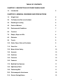
1
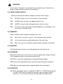
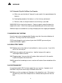
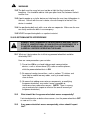
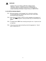
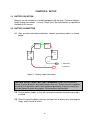
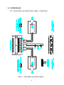
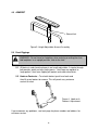
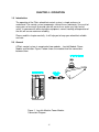
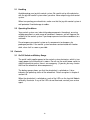
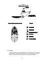
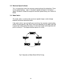
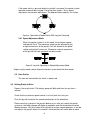
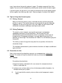
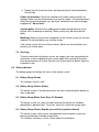
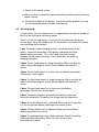
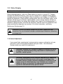
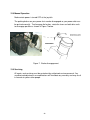
Owner’s Manual
REGENCY POWER WHEELCHAIR
MODEL: 7700
DANGER: ELECTROMAGNETIC INTERFERENCE (EMI) MAY CAUSE
ERRATIC, UNINTENTIONAL OR UNCONTROLLED MOVEMENT OF A
POWER WHEELCHAIR! READ AND FOLLOW THE INSTRUCTIONS AND
SAFETY PRECAUTIONS IN THIS MANUAL BEFORE OPERATING EQUIPMENT.
THE SERIAL NUMBER WILL BE FOUND ON THE LOWER PART OF THE CHAIR
FRAME. RECORD NUMBER BELOW:
SERIAL NUMBER:
REGENCY XLC
DATE OF PURCHASE:
by GENDRON
520 W. MULBERRY ST. iBRYAN, OH 43506
1-800-537-2521i
iFAX (419) 636-9261
All Gendron Products are manufactured in the U.S.A.
Form No. 7700 Manual (12/14)
© Gendron 2000
TABLE OF CONTENTS
CHAPTER 1: DESCRIPTION OF POWER WHEELCHAIR
1.0
Introduction
5
CHAPTER 2: GENERAL WARNINGS AND PRECAUTIONS
1.0
Weight Limit
6
2.0
To Reduce the Risk of an Accident
6
3.0
Reaching or Leaning
6
4.0
Center of Balance
6
5.0
Environmental Conditions
7
6.0
Transfers
7
7.0
Ramps, Slopes or Hills
8
8.0
Obstacles
9
9.0
Terrain
9
10.0
Curbs, Steps, Stairs or Escalators
9
11.0
Street Use
9
12.0
Motor Vehicle Safety
10
13.0
Armrests
10
14.0
Cushions
10
15.0
Fasteners
10
16.0
Footrests
10
17.0
Modified Seat Systems
11
18.0
Upholstery Fabric
11
19.0
Positioning Belt
11
20.0
Electromagnetic Interference
12
21.0
Electric Parking Brakes
13
2
CHAPTER 3: SETUP
1.0
Battery Selection
14
2.0
Battery Connection
14
3.0
Power Module
15
4.0
Armrest
16
5.0
Front Riggings
16
CHAPTER 4: OPERATION
1.0
Introduction
17
2.0
General
2.1 Handling
2.2 Operating Conditions
17
18
18
3.0
Controls
3.1 On/Off Switch and Battery Gauge
3.2 Joystick
3.3 Maximum Speed Indicator
3.4 Mode Switch
3.4.1 Speed Adjustment Mode
3.5 Horn Switch
18
18
20
20
20
21
21
4.0
Getting Ready to Drive
21
5.0
Tips for Using Your Control System
5.1 Driving – General
5.2 Driving – Technique
22
22
22
6.0
Precautions for use
6.1 Hazards
22
22
7.0
Safety Checks
7.1 Daily Checks
7.2 Weekly Checks
7.3 Servicing
23
23
23
24
8.0
Status Indication
8.1 Battery Gauge Steady
8.2 Battery Gauge Flashes Slowly
8.3 Battery Gauge Blinks Once Every 2.5 Seconds
8.4 Battery Gauge Flashes Rapidly
24
24
24
24
24
3
8.5 Self-Help Guide
25
9.0
Battery Gauge
9.1 How to Read a TruCharge Battery Gauge
26
26
10.0
Battery Charging
27
11.0
Control Adjustment
27
12.0
Manual Operation
28
13.0
Servicing
28
CHAPTER 5: MAINTENANCE & TROUBLE SHOOTING
1.0
Introduction
29
2.0
Maintenance Tips
2.1 Monthly Checks
2.2 Tires
2.3 8” Casters
2.4 13” Rear Drive Wheel
2.5 Lubrication
2.6 Cleaning
2.7 Seat and Back Upholstery
29
29
29
29
30
30
30
30
3.0
Battery Maintenance
31
4.0
Storage Tips
32
5.0
Troubleshooting
32
6.0
Operational Problems
32
CHAPTER 6: RAMP DESIGN
1.0
Ramps at Work
33
FEATURES AND SPECIFICATIONS
34
LIMITED WARRANTY
35
APPENDIX
Radio Wave/Electromagnetic Effects
36
4
CHAPTER 1: DESCRIPTION OF POWER WHEELCHAIR
1.0 Introduction
The Gendron Regency Power Wheelchair is a medium to heavy duty, rear wheel
drive power wheelchair. This device provides a means of mobility for users with a
body mass up to 364 kg. (800 lbs.) combined weight of patient and driver
The Regency Power Wheelchair consists of a seat & frame assembly, armrests, front
casters and footrests. As a motorized wheelchair, the unit also consists of two
motors with electric brakes, drive wheels, two 12 V. D.C. batteries and a controller
with joystick.
The joystick is user interfaced. It transfers the commands of the user to drive the
chair. When the user activates the joystick, the controller receives a signal to release
the brakes. With the brake released, the chair is allowed to move in the direction the
joystick is actuated. When the user releases the joystick, the chair slows to a stop
and the brake is automatically re-engaged. The electric parking brakes allow the
user to stop by letting go of the joystick.
If the chair loses power, the brakes are automatically engaged and the chair comes
to a stop. To prevent the user from being stranded, the chair may be pushed. The
parking brakes can be manually disengaged which allows the chair to be easily
pushed by an attendant.
The Pilot + (LR80) joystick module used on the Regency Power Wheelchair was
designed and developed to control the D.C. Drive System. The motors and batteries
are connected to the power module, which contains all the control, monitoring, and
switching circuitry necessary to drive a pair of brushed D.C. electric motors and
control two solenoid-operated parking brakes. A data cable connects the power
module to a control module, which contains a joystick and the electronics necessary
to convert its signals into digital commands for the power module. The joystick
module also contains a keypad, with an on-off switch and keys giving access to other
controller functions. A standard XLR socket is provided on the joystick module for
connection of the battery charger.
“Warning – Do not drive your wheelchair on slick or slippery surfaces of any kind.”
5
CHAPTER 2: GENERAL WARNINGS AND PRECAUTIONS
WARNINGS
Heed all warnings in this section. If you fail to do so, a fall, tip over or loss of
control may occur and cause severe injury to the user or others.
1.0 WEIGHT LIMIT
NEVER exceed the weight limit of 364 kg. (800) lbs. (model 7700), for combined
weight of user, patient and items carried. Exceeding weight limit may cause the chair
to fail.
2.0 TO REDUCE THE RISK OF AN ACCIDENT
2.1 BEFORE driving you should be trained in the safe use of a power chair by your
health care professional.
2.2 Get to know the areas where you plan to use your chair. Look for hazards and
learn how to avoid them.
2.3 Avoid a hard shock such as striking a curb. If this does occur, the vehicle
should be stopped and inspected for damage. Any damage should be repaired
before restarting and operating the equipment.
3.0 REACHING OR LEANING
If you reach or lean, it will affect the center of balance of your chair. This may cause
you to fall or tip over. When in doubt, ask for help or use a device to extend your
reach.
3.1 NEVER reach or lean if you must shift your weight sideways or rise up off the
seat.
3.2 NEVER reach or lean if you must move forward in your seat to do so. Always
keep your buttocks in contact with the backrest.
3.3 NEVER reach with both hands (you may not be able to catch yourself to prevent
a fall if the chair tips.)
4.0 CENTER OF BALANCE
The point where this chair will tip forward, back or to the side depends on its center of
balance and stability. How your chair is set up, the options you select and the
changes you make may affect the risk of a fall or tip over.
6
WARNINGS
4.1 THE CENTER OF BALANCE IS AFFECTED BY:
a. A change in the seat height of your chair by adding a seat cushion.
b. Changes in your body position, posture or weight distribution.
c. Driving your chair on a ramp or slope.
d. The use of a back cushion insert, or the amount or location of added weight.
4.2 TO REDUCE THE RISK OF AN ACCIDENT:
a. Consult your doctor, nurse, therapist or your authorized supplier BEFORE
you modify or adjust this chair. You may need to make other changes to
correct the center of balance.
b. Use the anti-tip wheels that were supplied with your chair.
5.0 ENVIRONMENTAL CONDITIONS
5.1 Contact with water or excess moisture may cause your chair to rust, corrode or
cause your joystick control not to function.
5.2 Do not store or use your chair in a hot or cold environment (Below 35º F or
above 110º F).
6.0 TRANSFERS
It is dangerous to transfer on your own. It requires good balance and agility.
To Avoid A Fall:
6.1 Work with your health care professional to learn safe methods of transfer.
a. Learn how to position and support yourself during a transfer.
b. Until you know how to do a safe transfer on your own, get help.
6.2 Before you transfer, turn the power off on your joystick. This locks the brakes
and keeps the rear wheels from rolling. However, this will not keep your chair
from sliding away from you or tipping.
6.3 Move your chair as close as you can to the bed or seat and use a transfer board.
6.4 Move or swing footrests out of the way. Make sure your feet do not catch in the
space between the footrests.
7
WARNINGS
6.5 Avoid putting weight on the footrests as this may cause the chair to tip.
Armrests must be moved out of the way.
6.6 Transferring as far back in the seat surface as possible will reduce the risk that
the chair will tip or move.
7.0 RAMPS, SLOPES or HILLS
Driving on a slope, ramp or hill will change the center of balance of your chair. Your
chair is less stable when it is at an angle. Anti-tip tubes may not prevent a fall or tip
over. Use extreme caution when going up or down ramps, slopes, or hills.
7.1 Do not use your chair on a slope grade steeper than 10%. (A 10% slope grade
means one foot in elevation for every ten feet of slope length. See page 34.)
7.2 Always go as straight up and as straight down as you can. (Do not “cut the
corner” on a ramp, slope, or hill.)
7.3 Do not turn or change direction on a ramp, slope, or hill.
7.4 Always stay in the CENTER of a ramp. Make sure ramp is wide enough to avoid
the risk of a fall or tip over.
7.5 Do not stop on a incline. If you attempt to stop, you may lose control of your
chair.
7.6 NEVER attempt to climb inclines covered with water, ice, an oil film, or other
foreign objects. Unexpected loss of control may occur, resulting in personal
injury or equipment damage.
7.7 To Reduce The Risk Of A Fall Or Tip Over:
a. Do not operate your chair on wet or slippery surfaces.
b. Beware of a change in grade on an incline (or a lip, bump or depression).
These may cause a fall or tip over.
c. Watch for a drop-off at the bottom of a slope or hill. A drop-off as small as ¾
inch can stop a front caster and cause the chair to tip forward.
d. Lean your body UPHILL. This will help adjust for the change in the center of
balance caused by the slope or hill.
e. If you go too fast, on a down slope or hill you may lose control.
8
WARNINGS
f. NEVER go down a slope or hill backwards. A fast stop in reverse may also
lift the front wheels.
8.0 Obstacles
Obstacles and road hazards (such as potholes and broken pavement) can damage
your chair and may cause a fall, tip over or loss of control. To avoid these risks:
8.1 Keep a lookout for danger – scan the area well ahead of your chair as you drive.
8.2 Make sure the floor areas where you live and work are level and free of
obstacles.
8.3 Remove or cover threshold strips between rooms.
8.4 Install a ramp at entry or exit doors. Make sure there is not a drop off at the top
or bottom of the ramp.
8.5 To Help Correct Your Center Of Balance:
a. Lean your upper body FORWARD slightly as you go UP over an obstacle.
b. Press your upper body BACKWARD as you go DOWN from a higher to a
lower level.
8.6 Keep anti-tip wheels in place at all times.
9.0 TERRAIN
9.1 Your chair is designed for use on firm, even surfaces such as concrete, asphalt
and indoor floors and carpeting.
9.2 Do not operate your chair in sand, loose soil or over rough terrain. This may
damage wheels or axles or loosen fasteners of your chair.
9.3 Avoid holes in the terrain, drop-offs and other hidden hazards.
9.4 Do not drive your chair on a wet or slick surface.
10.0 CURBS, STEPS, STAIRS OR ESCALATOR
10.1 Do not try to climb or descend a curb or step.
10.2 NEVER use this chair on stairs or escalator, even with an attendant. If you do, a
fall or tip over is likely.
11.0 STREET USE
9
WARNINGS
In most states, wheelchairs are not legal for use on public roads. Be alert to the
danger of motor vehicles on roads or in parking lots.
12.0 MOTOR VEHICLE SAFETY
Wheelchairs do not meet federal standards for motor vehicle seating.
12.1
NEVER let anyone sit in this chair while in a moving vehicle.
12.2
ALWAYS move the rider to an approved vehicle seat.
12.3
ALWAYS secure the rider with proper motor vehicle restraints.
12.4
This chair is heavy and should never be loaded into an automobile. (Use a
van or truck to transport chair.)
13.0 ARMRESTS
Armrests detach and will not bear the weight of this chair.
13.1
Never lift this chair by its armrests. They may come loose or break.
13.2
Lift this chair only by non-detachable parts of the main frame.
13.3
Make sure armrests are locked in position before entering or exiting chair.
14.0 CUSHIONS
14.1 Standard foam cushions are not designed for the relief of pressure.
15.0 FASTENERS
Many of the screws, bolts and nuts on this chair are special high-strength fasteners.
Use of improper fasteners may cause your chair to fail.
15.1 ONLY use fasteners provided by an authorized Gendron dealer.
15.2 Over or under-tightened fasteners may fail or cause damage to chair parts.
15.3 If bolts or screws become loose, properly tighten them immediately.
16.0 FOOTRESTS
16.1 At the lowest point, footrests should be AT LEAST 2 ½ INCHES off the ground.
If set too LOW, they may “hang up” on obstacles you can expect to find in
normal use. This may cause the chair to stop suddenly and tip forward.
10
WARNINGS
16.2 To Avoid A Trip Or Fall When You Transfer:
a. Make sure your feet do not “hang up” or get caught in the space between the
footrests.
b. Avoid putting weight on the footrests, as the chair may tip forward.
c. Remove, slide, or swing the footrests out of the way, if possible.
16.3 NEVER lift this chair by the footrests. Footrests detach and will not bear the
weight of this chair. Lift this chair only by non-detachable parts of the main frame.
16.4 Heel loops are available for assisting in keeping feet from slipping off footplates.
17.0 MODIFIED SEAT SYSTEMS
Use of a seat system not approved by Gendron may alter the center of balance of
this chair. This may cause the chair to tip over.
17.1 Do not change the seat system of your chair UNLESS you consult your
authorized Gendron supplier.
18.0 UPHOLSTERY FABRIC
18.1 Replace worn or torn fabric of seat and back as soon as you can. If you fail to
do so, the seat may fail.
18.2 Fabric may weaken with age and use. Look for fraying or thin spots or
stretching of fabric at corners.
18.3 “Dropping down” into your chair will weaken fabric and result in the need to
inspect and replace seat more often.
18.4 Be aware that laundering or excess moisture will reduce flame retardation of the
fabric.
19.0 POSITIONING BELT
Use positioning belts ONLY to help support the user’s posture. Improper use of
these belts may cause severe injury to or death of the rider.
19.1 Make sure the user does not slide down in the wheelchair seat. If this occurs,
the rider may suffer chest compression or suffocate due to pressure from the
belts.
11
WARNINGS
19.2 The belts must be snug, but must not be so tight that they interfere with
breathing. You should be able to slide your open hand, flat, between the belt
and the user.
19.3 A pelvic wedge or a similar device can help keep the user from sliding down in
the seat. Consult with the user’s doctor, nurse or therapist to find out if the
device is needed.
19.4 Use positioning belts only with a user who can cooperate. Make sure the user
can easily remove the belts in an emergency.
19.5 NEVER use positioning belts as a patient restraint.
20.0 ELECTROMAGNETIC INTERFERENCE
DANGER: ELECTROMAGNETIC INTERFERENCE (EMI) MAY CAUSE
ERRATIC, UNINTENTIONAL OR UNCONTROLLED MOVEMENT OF A
POWERED WHEELCHAIR! READ AND FOLLOW INFORMATION
CAREFULLY BEFORE OPERATING THE CHAIR.
20.1 What can I do to reduce the risk that my powered wheelchair could be
affected by EMI?
Here are some precautions you can take:
1) Do not turn ON or use hand-held personal communication
devices, such as citizens band (CB) radios or cellular phones,
while the powered wheelchair is ON.
2) Be aware of nearby transmitters, such as radio or TV stations and
hand-held or mobile two-way radios, and try to avoid coming
close to them.
3) Be aware that adding accessories or components, or modifying
the power wheelchair, may make it more susceptible to
interference from radio wave sources. (NOTE: There is no easy
way to evaluate their impact or effect on the overall immunity of
the power wheelchair).
20.2
What should I do if my power wheelchair moves unexpectedly?
If unintended motion or brake release occurs, turn the power wheelchair OFF
as soon as it is safe.
20.3
If my power wheelchair moves unexpectedly, where should I report
this?
12
WARNINGS
Gendron knows of no incidents of EMI with a Regency Power
Wheelchair. However, if you believe you have experienced an
unintended motion of your power wheelchair you should report the
incident immediately to Gendron Customer Service at 1-800-537-2521.
21.0 ELECTRIC PARKING BRAKES
21.1
When parking brakes are disengaged, there is absolutely no braking.
The disengaged position should only be used on a level surface when
manually pushing the wheelchair.
21.2
Make certain both BRAKE LEVERS are either engaged or disengaged at all
times. Otherwise, a dangerous steering situation may result when brakes are
applied.
21.3
Disengage brakes ONLY when manually pushing the chair. Joystick must be
in off position.
21.4
If chair turns to one side when backing, check disengaging lever. Consult
dealer if problem persists.
13
CHAPTER 3: SET UP
1.0 BATTERY SELECTION
Batteries are not included as standard equipment with the chair. Purchase batteries
locally through your dealer. Use only “Deep Cycle” Gel-Cell batteries as specified in
the back of this manual.
2.0 BATTERY CONNECTION
2.1 After you have selected your batteries, connect your battery cables, as shown
below:
A
BL
CK
CIRCUIT
BREAKER
GREEN
CIRCUIT
BREAKER
RE
D
+
-
BATTERY
"B"
BATTERY
"A"
-
+
BLACK
BLACK
RED
RED
( - NEGATIVE)
( + POSITIVE)
Figure 1. Battery Cable Connection
CAUTION: DO NOT SHORT BATTERY TERMINALS. Before installing battery,
remove all metal bracelets, wristwatch bands, rings, etc. Positive terminal should be
connected first to prevent sparks from accidental grounding. At no time should any
wires be allowed to touch one another. All connections must be tight.
2.2 Position battery cables so they will not be pinched when the battery case top is
installed.
2.3 Place the top of the battery case on the lower half of battery case and wrap the
straps across the lid to fasten.
14
3.0 POWER MODULE
3.1 Connect motors and communications cables as shown below:
Figure 2. Power Module Connection Diagram
15
4.0 ARMREST
R R
Release Knob
Figure 3. Height Adjustable Armrest Assembly
5.0 Front Riggings
WARNING - Do not stand on footplates when entering or exiting the chair;
fold footplates in an upright position, slide to the side.
5.1 All footrests and elevating legrests are length adjustable. A simple throughbolt provides quick and easy adjustments. Heel loops are optional to
keep patient’s feet from slipping off footrest and under wheelchair.
5.2 Hook-on Footrests – To unlatch footrest push lever back and
then lift up on footrest to remove. This will permit easy entrance
and exit to chair.
Figure 4. Hook-on &
Footrest Adjustment.
If you encounter any problems, see front page for phone number and address for
customer service.
16
CHAPTER 4: OPERATION
1.0 Introduction
The operation of the Pilot+ wheelchair control system is simple and easy to
understand. The control system incorporates state-of-the-art electronics, the result of
many years of research, to provide you with ease of use and a very high level of
safety. In common with other electronic equipment, correct handling and operation of
the unit will ensure maximum reliability.
Please read this chapter carefully - it will help you to keep your wheelchair reliable
and safe.
2.0 General
A Pilot+ control system is comprised of two modules - Joystick Module, Power
Module and Actuator. Figure 1 below shows the modules and the connections
between them.
Figure 1. Joystick Module, Power Module
Connection Diagram
17
2.1 Handling
Avoid bumping your joystick control system. Be careful not to strike obstacles
with the joystick control system when you drive. Never drop the joystick control
system.
When transporting your wheelchair, make sure that the joystick control system is
well protected. Avoid damage to cables.
2.2 Operating Conditions
Your control system uses industrial-grade components throughout, ensuring
reliable operation in a wide range of conditions. However, you will improve the
reliability of the control system if you keep exposure to extreme conditions to a
minimum.
Do not expose your control system or its components to dampness for
prolonged periods. If the control system becomes contaminated with food or
drink, clean it off as soon as possible.
3.0 Controls
3.1 On/Off Switch and Battery Gauge
The on/off switch applies power to the control system electronics, which in turn
supply power to the wheelchair’s motors. Do not use the on/off power switch to
stop the wheelchair unless there is an emergency. (If you do, you may shorten
the life of the wheelchair drive components).
The battery gauge shows you that the wheelchair is switched on. It also
indicates the operating status of the wheelchair. Details are given in chapter 4
section 8.0.
When the wheelchair is switched on, each of the LEDs on the Joystick Module
will briefly illuminate. If any of the LEDs do not illuminate, contact your service
agent.
18
Figure 2
Joystick Module Details
Joystick Module without Lighting
Controls
3.2 Joystick
The joystick controls the speed and direction of the wheelchair. The further you
push the joystick from the center position, the faster the wheelchair will move.
When you release the joystick, the brakes are automatically applied.
19
3.3 Maximum Speed Indicator
This is a gauge that shows the maximum speed setting of the wheelchair. There
are five speed settings - step 1 is the lowest speed and step 5 is the highest
speed. For details of how to change the maximum speed setting, see section 3.4
below.
3.4 Mode Switch
The mode switch is used to make maximum speed changes and to change
between wheelchair operation modes.
If the mode switch is pressed while you are driving, the maximum speed setting
will be increased by one step. Each successive operation of the mode switch will
increase the setting, when the setting is at 5 the next mode switch operation will
put the setting to 1. The diagram below explains this action.
Fig. 3 Operation of Mode Switch While Driving
20
If the mode switch is pressed when the joystick is centered, the control system
operation mode will be changed. There are three modes - drive, speed
adjustment and actuator adjustment. The diagram below explains this action.
Figure 4. Operation of Mode Switch With Joystick Centered
3.4.1 Speed Adjustment Mode
When the control system is in this mode, the maximum speed
indicator will flash. The maximum speed can be adjusted by left
or right movements of the joystick. Left will decrease the speed
setting and right will increase it. Forward or reverse movements
of the joystick will take you back into drive mode.
Figure 5. Joystick Operation in Speed Adjustment Mode
Depressing the mode switch will put the control system back into drive mode.
3.5 Horn Switch
The horn will sound while the switch is depressed.
4.0 Getting Ready to Drive
Depress the on/off switch. The battery gauge will blink and then turn on after a
second.
Check that the maximum speed control is set to a level that suits you.
Push the joystick to control the speed and direction of the wheelchair.
Please note that if you push the joystick before or just after you switch the control
system on, the battery gauge will ripple up and down and the wheelchair will not be
allowed to move. You must release the joystick to resume normal operation. If you do
not release the joystick within five seconds, the wheelchair will not be able to move
21
even if you release the joystick and push it again. The battery gauge will then flash
rapidly. You can reset this condition by switching the control system off and on again.
If you do not push the joystick as you switch the wheelchair on and the battery gauge
flashes rapidly, then there may be a fault. Refer to chapter 4 section 8.4 for details.
5.0 Tips for Using Your Control system
5.1 Driving - General
Make sure that the control system is mounted securely and that the joystick
position is correct. The hand or limb you use to operate the joystick should be
supported. Do not use the joystick as the sole support for your hand or limb wheelchair movements and bumps could upset your control.
5.2 Driving Technique
The control system interprets your joystick movements and produces
appropriate movements of your wheelchair. You will need very little
concentration to control the wheelchair, which is especially useful if you are
inexperienced. One popular technique is to simply point the joystick in the
direction you want to go. The wheelchair will "home-in" on the direction you push
the joystick.
The further you push the joystick away from the rest position, the faster the
wheelchair will go.
The intelligent speed control system minimizes the effects of slopes and different
types of terrain.
6.0 Precautions for Use
Note: In the event of the wheelchair moving in an unexpected way, release the
joystick. This action will stop the wheelchair under any circumstances.
6.1 Hazards
Do not drive the wheelchair:
i) beyond restrictions indicated in this user manual, for example maximum
inclines, curb height etc.
ii) in places or on surfaces where a loss of wheel grip could be hazardous, for
example on wet grassy slopes.
iii)
if you know that the control system or other crucial components require
repair.
22
WARNING: Although the Pilot+ control system is designed to be
extremely reliable and each unit is rigorously tested during
manufacture, the possibility of a system malfunction always exists
(however small the probability). Under some conditions of system
malfunction, the control system must (for safety reasons) stop the
chair instantaneously.
It is recommended by Gendron that a seat belt be purchased and used at all
times when the wheelchair is in motion. Gendron, Inc. accepts no liability for
losses of any kind arising from the unexpected stopping of the wheelchair, or
arising from the improper use of the wheelchair or control system.
7.0
Safety Checks
The electronic circuits in your control system have been designed to be extremely
safe and reliable. The on-board microcomputer carries out safety checks at up to 100
times per second. To supplement this safety monitoring, you should carry out the
following periodic checks.
7.1 Daily Checks
Joystick: With the control system switched off, check that the joystick is not
bent or damaged and that it returns to the center when you push and release it.
If there is a problem, do not continue with the safety checks and contact your
service agent.
7.2 Weekly Checks
Solenoid (parking) brake: This test should be carried out on a level floor with at
least 40 inches of clear space around the wheelchair.
i) Switch on the control system.
ii) Check that the battery gauge remains on, or flashes slowly, after one
second.
iii) Push the joystick slowly forwards until you hear the parking brakes (click)
operate. The chair may start to move.
iv) Immediately release the joystick. You must be able to hear each parking
brake operate (click) within a few seconds.
23
v) Repeat the test three more times, pushing the joystick slowly backwards,
left and right.
Cables & Connectors: Check the condition of all cables and connectors for
damage. Make sure that all connectors are securely mated. The communication
cable from joystick to controller has “push pull” connectors with tabs for proper
engagement. Do not twist!
Joystick gaiter: Check the thin rubber gaiter or boot, around the base of the
joystick shaft, for damage or splitting. Check visually only; do not handle the
gaiter.
Mounting: Make sure that all the components of the control system are securely
mounted. Do not overtighten any securing screws.
If the control system fails any of these checks, do not use the wheelchair and
contact your service agent.
7.3 Servicing
To ensure continued satisfactory service, we suggest you have your wheelchair
and control system inspected by your service agent after a period of 3 months
from commencement of service. Contact your service agent for details when the
inspection is due.
8.0 Status Indication
The battery gauge will indicate the status of the control system.
8.1 Battery Gauge Steady
This indicates that all is well.
8.2 Battery Gauge Flashes Slowly
The control system is functioning correctly, but you should charge the battery as
soon as possible.
8.3 Battery Gauge Blinks Once Every 2.5 Seconds
The control system has “gone to sleep” because the joystick has not been
operated for a period of time. To re-start, switch the system off and on again.
8.4 Battery Gauge Flashes Rapidly (even with the joystick released)
The control system safety circuits have operated and the control system has
been prevented from moving the wheelchair.
This indicates that there is a fault. Please follow this procedure:
24
i) Switch off the control system.
ii) Make sure that all connectors on the wheelchair and the control system are
mated securely.
iii) Check the condition of the battery. If you can't find the problem, try using
the self-help guide given in chapter 4 section 8.5.
8.5 Self-Help Guide
If a fault occurs, you can find out what has happened by counting the number of
bars that are flashing on the battery gauge.
Here is a list of self-help actions. Try to use this list before contacting your
service agent. Go to the number in the list that matches the number of flashing
bars and follow the instructions.
1 bar: The battery needs charging or there is a bad connection to the
battery. Check the connections to the battery and check the Power
Module battery connector. This is the 2-pole connector situated
between the two motor connectors. If the connections are good, try
charging the battery.
2 bars: The left-hand motor has a bad connection. Make sure that the
motor is connected properly and the Power Module connector M1 is
secure.
3 bars: The left-hand motor has a short circuit to a battery connection.
Contact your service agent.
4 bars: The right hand motor has a bad connection. Make sure that the
motor is connected properly and the Power Module connector M2 is
secure.
5 bars: The right hand motor has a short circuit to a battery
connection. Contact your service agent.
6 bars: The battery charger is preventing the control system from
driving the wheelchair. Disconnect the charger from the wheelchair.
7 bars: A Joystick Module fault is indicated. Make sure that the joystick
is in the rest position before switching on the control system.
8 bars: A Power Module fault is indicated. Make sure that all Power
Module connections are secure.
9 bars: The parking brakes have a bad connection. Check the parking
brake and motor connections. Make sure the control system
connections are secure.
25
10 bars: An excessive voltage has been applied to the control system.
This is usually caused by a poor battery connection. Check the battery
and Power Module connections.
Switch on the control system again and try to drive the wheelchair. If the safety
circuits operate again, switch off and do not try to use the wheelchair. Contact
your service agent.
9.0 Battery Gauge
The battery gauge is included to let you know how much charge is left in your
batteries. The best way for you to use the gauge is to learn how it behaves as you
drive the wheelchair. Like the fuel gauge in a car, it is not completely accurate, but it
will help you avoid running out of "fuel".
The battery gauge works in the following way:
When you switch on the control system, the battery gauge shows an estimate of the
remaining battery charge.
The battery gauge gives you a more accurate reading about a minute after you start
driving the wheelchair.
Note: When you replace worn out batteries, fit the type recommended in this manual.
If you use another type, the battery gauge may be inaccurate.
The amount of charge in your batteries depends on a number of factors, including the
way you use your wheelchair, the temperature of the batteries, their age and the way
they are made. These factors will affect the distance you can travel in your
wheelchair. All wheelchair batteries will gradually lose their capacity as they age.
The most important factor that reduces the life of your batteries is the amount of
charge you take from the batteries before you recharge them. Battery life is also
reduced by the number of times you charge and discharge the batteries. To make
your batteries last longer, do not allow them to become completely flat. Always
recharge your batteries promptly after they are discharged.
If your battery gauge reading seems to fall more quickly than usual, your batteries
may be worn out.
9.1 How to Read a TruCharge Battery Gauge
If the battery gauge shows red, yellow and green, the batteries are charged. If
the battery gauge shows just red and yellow, then you should charge the
batteries as soon as you can.
If the battery gauge shows just red, either steady or flashing slowly, then you
should charge the batteries immediately.
26
10.0 Battery Charging
Caution – when charging batteries, low level radio noise or static may occur.
Before charging batteries, make sure Power button on Joystick is turned OFF. To begin
charging the wheelchair batteries, make sure the charger wire is plugged into the batterycharging socket on the Joystick Module. When the batteries are charging, it is UNSAFE to
operate the wheelchair. Plug the battery charger power wire into a wall outlet socket. A red
indicator will light up on the charger signaling power, and an orange indicator will light up
signaling charging. When the orange light changes color to green, the charging process is
complete. Unplug the power cord from the wall outlet, wind the cord on the wheelchair wire
wrap and wheelchair operation can continue. (For further information, see Battery
Maintenance Section page 31.)
WARNING: Use only the battery charger that has been supplied with your
wheelchair The use of incorrect chargers could damage the batteries, wheelchair
or charger itself.
11.0 Control Adjustment
If you cannot find a speed control, turning control or response setting that suits you,
the control system can be programmed to meet your needs. Your authorized
Gendron dealer can make these adjustments.
WARNING: Gendron, Inc., accepts no liability for losses of any kind
arising from unauthorized opening, adjustment or modifications to
the Pilot+ control system.
WARNING: Adjustments to the controller should only be conducted
by an authorized Gendron dealer with in-depth knowledge of the
electronic control systems. Incorrect adjustments could result in an
unsafe set-up of a wheelchair for a user. Gendron, Inc. accepts no
liability for losses of any kind if the adjustments of the control
system are altered from factory pre-set values.
27
12.0 Manual Operation
Make certain power is turned OFF at the joystick.
The parking brakes on your power chair can be disengaged so your power chair can
be pushed manually. To disengage the brakes, rotate the levers on both drive units
to disengage position as shown in Figure 7 below.
Figure 7. Brake disengagement
13.0 Servicing
All repairs and servicing must be carried out by authorized service personnel. Any
unauthorized adjustments or modifications will invalidate any warranty and may result
in hazards to you or other people
28
CHAPTER 5: MAINTENANCE & TROUBLE SHOOTING
WARNINGS!
If you fail to heed these warnings, your chair may fail and cause
severe injury to the user or others.
•
Inspect and maintain this chair as shown in the maintenance chart as shown on
page 31.
•
If you detect a problem, service or repair the chair before use as directed in this
manual.
•
At least once every 3 months, have a complete inspection, safety check and
service of your chair made by an authorized Gendron dealer.
1.0 INTRODUCTION
Proper maintenance will improve performance and extend the useful life of your chair.
Clean your chair regularly. This will help you find loose or worn parts and make your
chair easier to use.
Repair or replace loose, worn, bent or damaged parts.
To protect your investment, have all maintenance and repair work done by an
authorized Gendron dealer.
2.0 MAINTENANCE TIPS
2.1 Monthly Checks-All nuts, bolts, screws, rivets, tires, wheels and upholstery
should be checked each month for wear. If the end user is unable to perform
the required inspection, return the unit to a qualified Gendron dealer for proper
maintenance.
2.2 Tires-Worn tires will make your wheelchair difficult to operate. Both wheels
should be replaced at the same time to prevent chair from pulling to one side.
2.3 8” Casters-Wheel is secured to the caster fork by an axle bolt and nut. To
adjust, rotate bolt and lock with nut. Wheel should be snug but free spinning. If
the caster flutters or shimmies, remove the caster cap. Adjust the locknut
located under the caster cap. Take-up all play. Back off about ¼ turn. Replace
caster cap. If proper adjustment cannot be made, replace bearings and stem
with authorized Gendron parts.
Caution-Excessive bearing wear will result if wheels are too tight or too loose.
Improper adjustment will cause premature failure of bearings and axle bolts.
29
Figure 1. Drive Wheel Maintenance
2.4 13” Rear Drive Wheels-Secure self locking cap screw by tightening to 375 + 10
in. lb. with a torque wrench. Check screws at least once a month. Replace self
locking screw with Gendron part number P42713 after each removal. Do not
reuse. The tires are foam-filled. Do not attempt to inflate with air.
2.5 Lubrication - All bearings are lubricated and sealed at the factory for life.
Gearboxes are lubricated with “Chevron Black Pearl Grease.”
2.6 Cleaning - All components on your wheelchair can be cleaned with warm water
and mild detergent. Wipe dry immediately with a soft clean cloth. Do not use
high-pressure water spray, abrasive or spirit based cleaners to clean your
wheelchair.
2.7 Seat and back upholstery – Only premium grade nylon fabric is used.
Replace immediately if upholstery is ripped. To ensure comfort and uniform
appearance, both seat and back upholstery should be replaced together.
Warning - Laundering or moisture may reduce flame retardancy of
upholstery. Laundering may reduce the load rating of upholstery.
30
3.0
BATTERY MAINTENANCE
Batteries should be regarded as energy reservoirs similar to gasoline tanks on
automobiles. For proper function, batteries must have the proper amount of energy
(fuel) supply. The battery gauge on the joystick control will show how much running
time is remaining. (See chapter 4 section 8.0 in this manual.)
WARNING: Running your POWER WHEELCHAIR with discharged batteries
may cause the unit to operate erratically. Under continuous use, with fully
charged batteries, and total weight capacity, 364 kg. (800 pounds), battery
power will last approximately 90 minutes.
Charge your batteries every night. A twelve-hour charge with the charger provided
with your POWER WHEELCHAIR will usually be sufficient.
Frequent, long, and slow charges will yield a longer battery life than short fast
charges.
Caution – When charging batteries, low level radio noise or static may occur. Always
charge batteries in a well-ventilated room away from open flames, sparking devices,
radios, televisions, or other electrical devices.
MAINTENANCE CHART
Check:
Weekly
Brakes
All fasteners for
wear and tightness
Armrests
Axles & Axle Bolts
Wheels & Tires
Casters
Anti-tip Wheels
Frame
Upholstery
Lubricate Gearbox
Recommended Lubricant:
“Chevron Black Pearl Grease”
Service by Authorized Gendron
Supplier
a
3 months
6 months
a
a
a
a
a
a
a
a
a
a
31
4.0 STORAGE TIPS
Store your chair in a clean, dry area. If you fail to do so, parts may rust or corrode
and/or cause damage to controller.
Before each use, make sure your wheelchair is in proper working order. Inspect and
service items according to the “Maintenance Chart” on page 32.
If stored for more than three months, disconnect batteries and have your chair
inspected by an authorized Gendron dealer before use.
5.0
TROUBLESHOOTING
TROUBLE SHOOTING GUIDE
PROBLEM
CAUSE/REMEDY
Will not move
Check battery voltage.
Check wire connections and circuit breakers.
Make sure charger is unplugged.
Problems turning
Turns easier in the direction the front casters are trailing.
Check wire connections and that both motors are
operating.
Steering is not straight
Casters may be bent.
Check wire connections and assure that both motors are
operating.
Check that electric brakes are both engaged.
Will not Freewheel
Check that electric brakes are both disengaged.
Check push button on joystick, be sure power is off.
6.0 OPERATIONAL PROBLEMS
Most of the operational “problems” reported to the manufacturer turn out to be related
to the batteries. Before reporting a POWER WHEELCHAIR failure, carefully check
the following:
Check battery connections: If they are corroded, clean them thoroughly. Make sure
there are no nonconductive materials, such as grease, oil, or corrosive build up
between the connections, then tighten the connections.
Charge batteries for 12 hours: If, after charging, the above checks appear to be
satisfactory but the problem still exists with operation, contact your Gendron dealer.
32
CHAPTER 6: RAMP DESIGN
1.0 Ramps At Work
For your safety, ramps at work must meet all legal requirements for your area. We
recommend:
1.1 Width. At least four feet wide.
1.2 Guardrails. To reduce the risk of a fall, sides of ramp must have raised borders
or guardrails at least three inches high.
1.3 Slope Grade. Not more than a 10% slope grade. A 10% slope grade means
one foot in elevation for every ten feet of slope length. (See Figure 1. below.)
1.4 Surface. Flat and even, with a thin carpet or other non-skid material. Make
sure there are no lips, bumps or depressions.
1.5 Bracing. Ramp must be STURDY. You may need bracing so ramp does not
“bow” when you ride on it.
1.6 Avoid A Drop Off. You may need a section at the top or bottom to smooth out
the transition.
WARNING: The center of balance of your chair will change while driving
on a ramp. Do not turn or change direction. Stay in the center of the
ramp, and do not attempt to stop on the ramp.
1 Ft,
Level
10 Ft.
Figure 1. 10% Slope Grade
33
FEATURES AND SPECIFICATIONS
GENERAL DATA
Ball bearings
8” x 2” Caster Wheel
Sealed lubrication
13” Drive Wheel (Foam-Filled)
5 Amp automatic battery charger – UL Approved
MOTOR/DRIVE MODULE
Voltage:
Style:
Speed Forward:
Speed Reverse:
Current:
Gear Ratio:
24 V. DC operating range 18-30 V. DC
4 pole, brush type, permanent magnet
4.0 MPH Maximum
2.0 MPH Maximum
80-Ampere Maximum (Peak)
18:1
Maximum Grade: (1)
Maximum Weight: (2)
10%
364 kg (800 lbs.) Total - patient and attendant – Model 7700
CONTROL FEATURES
All solid state electronics
High efficiency and cool running
Electronic indication of battery charge
External speed adjustment
Fully proportional joystick control
Electronic fail or fault monitoring
Electronic current limit
Automatic battery isolation while charging
RECOMMENDED BATTERIES
Two 12 volt D.C. Deep Cycle Gel Cell
Battery Size (inches):
Approximate weight (pounds):
BCI Group size:
40 Amp Hours
9.4w x 5.4d x 9.6h
42 Each
22NF/24/24M
Some brands of gel cell, deep cycle batteries include: M-K, Donley, Johnson Controls,
Sears, GNB and Interstate. Contact your dealer for a distribution center near you.
(1)
Do not drive your power wheelchair on slick/slippery surfaces of any kind.
(2)
Maximum weight includes attendant weight, patient weight and any carry-on item
(back pack, oxygen tank holder, luggage, etc.
34
LIMITED WARRANTY
Gendron, Inc. warrants each “new” REGENCY POWER WHEELCHAIR sold to be free of
defects in material and workmanship. The following warranty applies to each of the major
modules from date of shipment from Gendron, Inc.:
(1) Joystick/Control Module .................................................... (6) Six-month warranty
(2) Motor/Brake/Drive Modules ............................................... (1) One-year warranty
(3) Seat, back, wheels, other components ............................. (1) One year warranty
(4) Battery Charger ................................................................. (1) One year warranty
(5) Frame ................................................................................ (3) Three-year warranty
Control modules, drive units, and battery chargers will be replaced if defective as major
service components. The customer will be billed for the replacement unit until the defective
unit is returned, at which time credit will be issued. Gendron will pay UPS ground service
only to ship the component to the customer. Misuse, negligence, or accident to the
Regency Power Wheelchair is not covered in this warranty. Repairs or alterations to the
Regency Power Wheelchair will not be covered under warranty unless they have been
authorized by Gendron, Inc. Gendron will not be responsible for any labor or material costs
resulting from unauthorized repairs. All unauthorized repairs, replacement parts, or
modifications may void all warranties.
This warranty gives you specific legal rights, and you may also have other rights, which
vary, from state to state. This warranty is in lieu of all other warranties, expressed or
implied, and is not assignable, nor transferable, by the purchaser.
Freight Damage - The carrier who delivers merchandise to your door is responsible for
loss and damages. Acceptance of the shipment by you is acknowledgement that all
articles were in good condition and properly packed. Therefore, all claims for loss or
damage must be filed immediately with the freight carrier. Should you need assistance
with the claim, call our customer service department at 800-537-2521.
Shortages - Check cartons carefully for shortages. Report shortages within 10 days after
order receipt.
Return Goods - Within 30 days from date of purchase, returns will be subject to a 15%
handling and restocking charge plus any additional costs resulting from damage. After 30
days from date of purchase, Gendron, Inc. reserves the right to not accept returned goods
for any reason. If the goods are accepted, the amount of credit will be at the discretion of
Gendron, Inc. Returned goods must be in new condition.
Do not return merchandise without prior authorization. All correspondence relating to this
warranty must indicate Model Number and Serial Number and be shipped to:
Gendron, Inc.
520 W Mulberry St Suite 100
Bryan, Ohio 43506
35
36
37