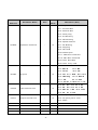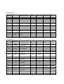
1
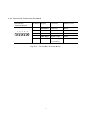
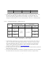
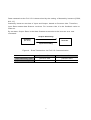
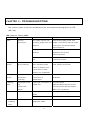
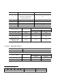
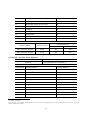
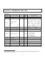
User Manual
DeviceNet
Option Board
for SV-iS5 Series
Read this manual carefully before using the DeviceNet Option
Board and follow the instructions exactly.
After reading this manual, keep it at handy for future reference.
LG Industrial Systems
Thank you for purchase of LG DeviceNet Option Board!
SAFETY PRECAUTIONS
Always follow safety precautions to prevent accidents and potential hazards from
occurring.
Safety precautions are classified into “WARNING” and “CAUTION” in this manual.
WARNING
CAUTION
Indicates a potentially hazardous situation
which, if not avoided, can result in serious injury
Indicates a potentially hazardous situation which,
if not avoided, can result in minor to moderate
injury, or serious damage to the product.
Throughout this manual we use the following two illustrations to make you aware of
safety considerations:
Identifies potential hazards under certain conditions.
Read the message and follow the instructions carefully.
Identifies shock hazards under certain conditions.
Particular attention should be directed because dangerous voltage may
be present.
Keep this manual at handy for quick reference.
CAUTION
Be sure to take ESD (Electrostatic Discharge) protection measures when you
touch the board.
Otherwise, the option board may get damaged due to static charges.
Implement wiring change on the Option Board after checking that
the power supply is off.
1
Otherwise, there is a danger of connecting error and damage to the board.
Be sure to fix inverter to option board tightly.
Otherwise, there is a danger of connecting error and damage to the board.
Be sure to install a termination resistor (120ohm, 1/4W) at the end of the
network.
Be sure to check parameter unit when setting parameters.
Otherwise, there is a danger of connecting error.
2
CHAPTER 1 - INTRODUCTION
By using a DeviceNet communication board, SV-iS5 inverter can be connected to a
DeviceNet network.
1.1.
Through LG DeviceNet Option Board…
Inverter can be controlled and monitored by PLC sequence program or any
Master Module.
Multiple inverters can be connected to one communication cable with
simple and easy installation, dramatically saving wiring, maintenance cost
and time.
Compatible with PC System, PLC and any controllers is available, making
Factory Automation more easily.
1.1.1. Vocabulary
In this manual we refer to the:
DeviceNet Option Board for iS5 series as the Option Board
iS5 series inverter as the inverter
1.2.
Kit Contents
The DeviceNet option board kit consists of:
DeviceNet Option Board, 1 pcs
5 pin Connector, 1 pcs
Mounting poles, 3 pcs
Installation Manual
1.3.
DeviceNet Option Board Specification
Device Type: AC Drives
Explicit Peer to Peer Messaging: Support
I/O Peer to Peer Messaging: N/A (Not Available)
Configuration Consistency Value: N/A
Faulted Node Recovery (Off-Line): Support
3
Baud Rate Support: 125, 250, 500 (kbps)
Master/Scanner (Predefined M/S Connection): Support
I/O Slave Messaging
- Polling: Support
- Bit Strobe, Cyclic, COS (Change of State): N/A
Range of Input Voltages: 11 – 25V DC
1.4.
Installing the Communication Card
1.4.1. Board Layout
Status LED
DeviceNet
Connector
Figure 1 – Board layout
1.4.2. Status LED
MS
(Module Status) LED
Checks the status of incoming power to option
board, CPU function and communication to the
Inverter.
NS
Checks the connection of option card on the
(Network Status) LED
Network and DeviceNet power status.
Note) Refer to Chapter 4 - TROUBLESHOOTING for more details.
4
Inverter
Connector
MS NS
1.4.3. DeviceNet Connection Terminal
DeviceNet
Terminal Signal
Function
Cable Color
1
Common
Common
Black
2
CAN Low
Signal Low
Blue
3
Shield
Shield
Bare
4
CAN High
Signal High
White
5
V+
Power supply
Red
Terminal Block
1
2
3
4
5
( 11-24VDC)
Figure 2 – DeviceNet Terminal Block
5
CHAPTER 2 - INSTALLING THE OPTION BOARD
2.1.
Installing the Option Board to the Inverter
Note) DeviceNet Option Board can be installed to the inverter having software V 1.05
and later.
Figure 3 – Installing the DeviceNet Board to the Inverter
2.1.1. Setting the DeviceNet Parameter
2.1.1.1.
Setting the MAC ID <COM Group, #10>
1. MAC ID (Media Access Control Identifier, Station Number) is a unique value to
identify nodes in the DeviceNet Network. When setting, you must ensure that the
each serial device on the network has a unique address.
2. Setting and changing MAC ID is available via keypad.
3. The factory default setting is DeviceNet address 63. If DPRAM communication
between Inverter and the Option card becomes faulty, the value will default to
Station Number 63.
6
Min Value
Max Value
Parameter Setting
0
63
COM Group, #10
MAC ID
4. When MAC ID is changed during Run, Option board is automatically reset to find
the device new MAC ID is allocated on the network. If a duplicate Mac ID is
checked, NS (Network Status) LED turns Solid Red. In this case, it should be
changed to different MAC ID. In the normal operation, LED color is flashing Green.
2.1.1.2.
Setting the Baud Rate < COM Group, #11>
Baud
Rate
Trunk Cable Length
Thick Cable
Drop Length
Thin Cable
Max Length
Total
125
500 m
156 m
kbps
(1640 ft.)
(512 ft.)
250
250 m
100 m
kbps
(820 ft.)
(328 ft.)
500
100 m
39m
kbps
(328 ft.)
(128ft.)
6 m (20 ft.)
78 m
(256 ft.)
Table 1 – Baud Rate vs. Cable Length
1. The Baud Rate determines the maximum length of the DeviceNet cable. Refer to
Table 1 to determine cable lengths and baud rates. The above is only met when
DeviceNet-dedicated cables are used. For more information on the DeviceNet
cables, makers and detail specifications, refer to the Open DeviceNet Vendor
Association (ODVA) homepage at “http://www.odva.org/”.
2. NS LED remains OFF when the setting of actual Network communication speed and
Baud Rate does not match.
3. Set the desirable Baud Rate via Keypad. Changing this parameter does not change
the actual data rate until power is cycled. Reset the inverter or request Reset
7
Service to the Inverter Reset Identity Object.
4. NS LED will turn to flashing Green when Network Baud Rate matches Baud Rate of
the option card and a unique MAC ID is allocated.
2.1.1.3.
Setting Assembly Instance
Assembly Instance has four types of Sending/Receiving data through Poll I/O
communication. Refer to Assembly Object in Chapter 7 for detailed information.
2.2.
Setting Other Parameters
2.2.1. Setting Option Mode [COM Group, #02]
Via DeviceNet
COM Group, #02 setting
Issuing Operating command only
Command
Issuing Frequency command only
Freq
Issuing Operating + Frequency command
Cmd+Freq
Table 2 – Setting Option Mode
Note) This setting supercedes setting in FU1 group.
2.2.2. Setting TimeOut [I/O, #49]
The factory default setting for TimeOut is 1 sec. When communication between inverter
and DeviceNet network is disrupted in the Run mode, inverter checks the communication
failure and performs operation under the setting in I/O group #48 until Master-setting
Time + preset TimeOut elapses.
2.3.
Poll I/O Connection
It is a Data transaction between Inverter and Scanner.
Input/output size: 4 bytes
Communication Rate: 0 (default)
Data Transaction: Poll I/O
8
Data transaction thru Poll I/O is determined by the setting of Assembly Instance [COM,
#12,13].
Assembly Instance consists of Input and Output, based on Scanner side. Therefore,
Input Data means data Scanner receives. For inverter side, it is the feedback value to
Scanner.
By contrast, Output Data is the data Scanner transmits to the Inverter as a new
command.
Output Assembly
Scanner
Inverter
(Ex:PLC)
Input Assembly
Figure 4 - Data Transaction via Poll I/O Communication
Scanner Side
Inverter Side
Input Assembly Data
Receive data
Transmit data
Output Assembly Data
Transmit data
Receive data
9
CHAPTER 3 - MODES OF OPERATION
3.1.
PowerUp Reset mode
During a powerup or reset, the option board:
1. Performs powerup initialization. First Module Status LED flashes Green for
0.25sec to Red for 0.25sec and then turns to Solid Green when DPRAM is in
normal operation.
2. Then, Network Status LED flashes Green for 0.25sec to Red for 0.25sec
3. After no duplicate MAC ID is detected, Network Status LED flashes Green,
indicating the option board is successfully connected to the Network. However,
communication with other nodes has not been initiated.
If the above steps is failed, follow the below steps. No action is required in the normal
operating state.
1. When DPRAM is not working properly, Module Status LED turns Solid Red. In
this case, Check the option board’s connection with Inverter first and cycle the
power.
2. When NS remains OFF, not flashing Green,
1) Check the DeviceNet Power
2) Check the Baud Rate of Network and the Option board matches.
When duplicate MAC ID error occurs, Network Status LED turns Solid Red. In this
case, allocate the different MAC ID via Keypad.
When the option board is in communication with other nodes, NS (Network Status)
LED turns Solid Green.
.
3.2.
When EMC (Explicit Message Connection) is established by
Scanner
Network Status LED turns green. During this state, if EMC setting is deactivated,
the LED will turn green after 10 seconds delay. Once EMC is connected, I/O
Connection setting is available. At this time, the Network Status LED will not change.
If I/O Connection is not established within given time, then Time Out will occur
10
and Network Status LED turns flashing Red. (Depending on the time setting of EMC,
the status can be changed to green again.)
11
CHAPTER 4 - TROUBLESHOOTING
The current status of Device and Network can be monitored through built-in LED
(MS, NS).
[NS (Network Status) LED]
LED
Status
Cause
Diagnostics
OFF
Off-Line
The option card is not
Check DeviceNet power and
(No Power)
receiving power from the
cable connections and the power
Network.
connection on the DeviceNet
terminal block.
Single node on the
Check DeviceNet Master node
network
operation for correct
Communication.
Incorrect Baud Rate is
Change the baud rate setting and
set.
reset the inverter.
Flashing
On-Line,
Communication is set
Normal operating status before
Green
Not Connected
after duplicate node
user makes connection.
check is finished, but
connection to other
node is not completed.
Solid
On-Line,
More than one EMC
Polled I/O connection is
Green
Connected
connection is
available.
(Link OK)
established.
Flashing
Connection Time-
Polled I/O connection is
Inverter Reset.
Red
Out
Timed Out
Request Reset Service to the
Solid Red
Critical Link
Inverter Reset Identity Object.
Failure.
Retry I/O connection.
Faults occurred
Duplicate MAC ID check
Change the setting of MAC ID.
failed
Bus Off State
Green
Flashing
Self- diagnostic
Device
is
Check for line connection
under
diagnostic mode.
Red
12
self-
Wait for a moment.
Red
Flashing
Communication
State of Communication
Fault
Fault due to the failure
Green
No action required.
to pass the Network
Access. Identity
communication Fault
Request is accepted
[MS (Module Status) LED]
LED
Off
Solid
Green
Solid Red
Status
No Power
5V Power is not applied
to the option card.
Diagnostics
Check the incoming power to
inverter is provided.
Check 5V power is ON.
Operational
Normal operation state
Unrecoverable
Data transaction through
Check the connection between
Fault
DPRAM is disrupted..
option card and Inverter.
Flashing
Green &
Cause
Self Test
Red
Device is in self-test
mode.
1. EDS(Electronic Data Sheet)
EDS files are specially formatted ASCII files that provide all of the information
necessary for a configuration tool such as the DeviceNet Manager, to access and alter
the parameters of a device. The EDS file contains information on the number of
parameters in a device and how those parameters are grouped together. Information
about each parameter is contained in this file such as parameter min, max, and default
values, parameter data format and scaling and the parameter name and units.
Install EDS files for iS5 to control iS5 parameters using DeviceNet Manager program.
This file can be downloaded from : http://www.lgis.com or contact your LG
representative.
13
CHAPTER 5 - DEVICENET DATA TABLES
Message
R: Read Only
R/W: Read / Write enable
<Device Profile>
AC/DC Drives: 0x 02
<Object Model>
Object Class Name
Class Code
Identity Object
0x01
Message Router
0x02
DeviceNet
0x03
Assembly
0x04
Connection
0x05
Motor Data
0x28
Control Supervisor
0x29
AC/DC Drive
0x2A
Inverter
0x64
< Class 1 - Identity Object>
Class Code
0x01
Instance
1 (All attributes are instance 1)
Attribute ID
Attribute Name
Access Method
1
Vendor ID
R
2
Device Type
R
3
Product Code
R
Revision
R
4
Major Revision (High Byte)
Minor Revision (Low Byte)
14
Attribute ID
Attribute Name
Access Method
5
Status
6
Serial Number
R
7
Product Name
R
1
Service Name
R
Implemented for:
Service Code
Class
Instance
Get_Attribute_Single
0x0E
No
Yes
Reset
0x05
No
Yes
Set_Attribute_Single
0x10
No
Yes
< Class 3 - DeviceNet Object >
Class Code
0x03
Instance
Attribute ID
1
1 (All attributes are instance 1)
Attribute Name
Access Method
2
1
MAC ID
R/W
2
Baud Rate
3
BOI
Not support
4
Bus-Off Counter
Not support
3
R/W
Status Attribute
8 (Recovera ble Minor
Bit number
0 (Owned)
Other Bits
Fault)
Meaning
Connected to the master
2
Range of Mac ID: 0 to 63
3
Baud Rate
DPRAM Erro r
Not support
Value
0
1
2
Baud Rate
125 kbps
250 kbps
500 kbps
15
Attribute ID
Attribute Name
Access Method
Allocation Information:
5
Allocation Choice Byte
4
R
Master ’s MAC ID
6
MAC ID Switch Changed
R
7
Baud Rate Changed
Not support
8
MAC ID Switch Value
Not support
9
Baud Rate Switch Value
Not support
Service Name
Implemented for:
Service Code
Class
Instance
Get_Attribute_Single
0x0E
Yes
Yes
Set_Attribute_Single
0x10
No
Yes
0x4B
No
Yes
0x4C
No
Yes
Allocate Master/Slave
Connection Set
Release Group2
Identifier Set
< Class 4 - Assembly Object >
Class Code
0x04
Instance
1 (All attributes are instance 1)
Service Name
4
Implemented for:
Service Code
Class
Instance
Get_Attribute_Single
0x0E
No
Yes
Set_Attribute_Single
0x10
No
Yes
Allocation Choice Byte
7
6
5
4
Not Supported
3
2
1
0
Polled
Explicit Message
16
< Output Assembly Data Attribute Format >
Instance
Byte
Bit 7
Bit 6
Bit 5
Bit 4
Bit 3
0
Bit 2
Bit 1
Bit 0
Fault
Run
Reset
Fwd
1
20
(100)
Speed Reference (Low Byte) – RPM unit
2
(Speed Reference (Low Byte) – Hz unit)
Speed Reference (High Byte) – RPM unit
3
(Speed Reference (High Byte) – Hz unit)
0
NetRef
NetCtrl
Fault
Run
Run
Reset
Rev
Fwd
1
21
(101)
Speed Reference (Low Byte) – RPM unit
2
(Speed Reference (Low Byte) – Hz unit)
Speed Reference (High Byte) – RPM unit
3
(Speed Reference (High Byte) – Hz unit)
Name
Related Attribute
Description
Run Fwd
Run Rev
Fault reset
Forward Run
Command
Reverse Run
Command
Class
Attr. ID
0x29
3
0x29
4
Fault Reset Command
0x29
12
NetRef
5
Not used
0x2A
4
NetCtrl
5
Not used
0x29
5
Speed Command
0x2A
8
Speed
Reference
5
Setting Reference Control and Run/Strop Control can Only be done via LCD Keypad. Therefore, NetRef,
NetCtrl in Instance 21 and 101 is not available.
17
< Input Assembly Data Attribute Format >
Instance
Byte
Bit 7
Bit 6
Bit 5
Bit 4
Bit 3
Bit 2
Bit 1
Run-
0
Bit 0
Faulted
ning1
1
70
(110)
Speed Reference (Low Byte) – RPM unit
2
(Speed Reference (Low Byte) – Hz unit)
Speed Reference (High Byte) – RPM unit
3
(Speed Reference (High Byte) – Hz unit)
0
71
At
Ref.
Ref
Ctrl
from
from
Net
Net
Ready
Run-
Run-
ning 2,
ning 1,
(Rev)
(Fwd)
Warning
1
Speed Reference (Low Byte) – RPM unit
(111)
2
(Speed Reference (Low Byte) – Hz unit)
Speed Reference (High Byte) – RPM unit
3
(Speed Reference (High Byte) – Hz unit)
Name
Faulted
Related Attribute
Description
DPRAM or Inverter
Class
Attr. ID
0x29
10
Error
Warning
Not Supported
0x29
11
Running1
Motor is running
0x29
7
0x29
8
Forward
Running2
Motor is running
Reverse
Ready
Motor is ready to run
0x29
9
Ctrl From Net
Run/Stop control
0x29
15
Ref From Net
Speed control
0x2A
29
18
Faulted
At Reference
Reach at Reference
0x2A
3
Speed
Drive State
Current Motor State
0x29
6
Speed Actual
Speed Command
0x2A
7
< Class 5 - Connection Object >
Class Code
0x05
1
Predefined EMC
2
Poll I/O
6, 7, 8, 9, 10
Dynamic EMC
Instance
Access Method
Attribute ID
Attribute Name
I/O
EMC
Established/
Established/
Timed Out
Deferred delete
1
State
R
R
2
Instance_type
R
R
3
TransportClass_trigger
R
R
4
Produced_connection_id
R/W
R
5
Consumed_connection_id
R/W
R
6
initial_comm_characteristics
R
R
7
Produced_connection_size
R
R
8
Consumed_connection_size
R
R
9
Expected_packet_rate
R/W
R/W
10 – 11
N/A
12
Watchdog_timeout_action
R/W
R/W
13
Produced_connection_path_ length
R
R
14
Produced_connection_path
R
R
15
Consumed_connection_path_
R
R
length
16
Consumed_connection_path
R
R
17
Production_inhibit_time
R/W
R
19
Service Name
Service Code
Implemented for:
Class
Instance
Get_Attribute_Single
0x0E
No
Yes
Reset
0x05
No
Yes
Set_Attribute_Single
0x10
No
Yes
<Class 28 - Motor Data Object >
Class Code
0x28
Instance
1 (All attributes are instance 1)
Attribute ID
Attribute Name
Access Method
3
MotorType
R
6
RatedCurrent
R/W
7
RatedVoltage
R
Service Name
Service Code
6
Implemented for:
Class
Instance
Get_Attribute_Single
0x0E
No
Yes
Set_Attribute_Single
0x10
No
Yes
< Class 29 - Control Supervisor Object >
Class Code
0x29
Instance
6
1 (All attributes are instance 1)
Attribute ID
Attribute Name
Access Method
3
Run 1 (Forward command)
R/W
4
Run 2 (Reverse command)
R/W
5
NetCtrl
6
State
7
R
R
MotorType Attribute Squirrel Cage Induction Motor: #7
7
NetCtrl Attribute: T his Attribute setting determines the control location for the motor. This value only can be
set through the keypad for the safety reason. Changing this via DeviceNet does not cause error and cannot affect
the setting.
20
Attribute ID
Attribute Name
Access Method
7
Running1 (Forward running)
R
8
Running2 (Reverse running)
R
9
Ready
R
10
Faulted
R
12
FaultRst
R/W
13
FaultCode
R
15
CtrlFromNet
R
Service Name
Service Code
Implemented for:
Class
Instance
Get_Attribute_Single
0x0E
No
Yes
Set_Attribute_Single
0x10
No
Yes
< Class 2A - AC/DC Drive Object >
Class Code
Instance
0x2A
1 (All attributes are instance 1)
Attribute ID
Attribute Name
Access Method
3
AtReference
R
8
4
NetRef
R/W
6
DriveMode
R/W
7
SpeedActual
R
8
SpeedRef
R/W
9
CurrentActual
R
29
RefFromNet
R
100
Actual Hz
R
101
Reference Hz
R/W
102
Acc. Time
R/W
103
Dec. Time
R/W
8
NetRef Attribute
This setting is only done via Keypad for safety reason. Changing this via DeviceNet does not cause error and
cannot affect the setting.
21
Service Name
Implemented for:
Service Code
Class
Instance
Get_Attribute_Single
0x0E
No
Yes
Set_Attribute_Single
0x10
No
Yes
< Class 64 - Inverter Object >
Class
0x64
Attribute Number
Code
Instance
1
DRV Group
iS5 Parameter code # + 1
2
FU1/FU2 Group
Same as iS5 Parameter code #
3
I/O Group
Same as iS5 Parameter code #
4
COM Group
Same as iS5 Parameter code #
5
APP Group
Same as iS5 Parameter code #
Note) Refer to iS5 inverter manual for reference of Attribute Number. It is the same as iS5
Parameter Code Number.
Service Name
Implemented for:
Service
Code
Class
Instance
Get_Attribute_Single
0x0E
Yes
Yes
Set_Attribute_Single
0x10
No
Yes
22
CHAPTER 6 - PARAMETER CODE (HEX)
<Common> 9
Parameter
Address
0x0000
0x0001
Parameter Name
Inverter Model
Applicable Motor
Rating
Read/
Unit
Data Value (Hex)
Write
-
R
-
R
4: SV-iS5
0: 0.75
1: 1.5
2: 2.2
3: 3.7
4: 5.5
5: 7.5
6: 11
7: 15
8: 18.5
9: 22
A: 30
B: 37
C: 45
D: 55
E: 75
F: 90
10:110
11: 132
12: 160
13: 200
14: 220
15: 280
16: 375
(Unit: kW)
0x0002
Inverter Input Voltage
-
R
0: 220V
1: 440V
0x0003
Software version
-
R
0100: Ver. 1.00,
0101: Ver 1.01
0x0005
Reference Frequency
0.01Hz
R/W
Bit 0: Stop
Bit 1: Forward Run
0x0006
Operation reference
-
R/W
Bit 2: Reverse Run
Bit 3: Fault Reset
Bit 4: Emergency Stop
0x0007
Accel time
0.1 sec
R/W
0x0008
Decel time
0.1 sec
R/W
0x0009
Output Current
0.1 A
R
0x000A
Output frequency
0.01 Hz
R
0x000B
Output voltage
0.1 V
R
0x000C
DC Link voltage
0.1 V
R
0x000D
Output power
0.1 kW
R
9
The changed value in Common affects the current setting but returns to the previous setting when power is
cycled or Inverter is reset. However, changing value is immediately reflected in other parame ter groups even in
the case of Reset or Power On/Off.
23
Parameter
Parameter Name
Address
Unit
Read/
Data Value (Hex)
Write
Bit 0: Stop
Bit 1: Forward Run
Bit 2: Reverse Run
Bit 3: Fault (Trip)
Bit 4: Accelerating
Bit 5: Decelerating
Bit 6: Speed reached
0x000E
Operation reference
-
R
Bit 7: DC Braking
Bit 8: Stopping
Bit 9: Not Used
Bit10: Brake Open
Bit 11: FWD Run Command
Bit 12: REV Run Command
Bit13: Rem. Run/Stop
Bit14: Rem. Freq. Cmd
0x000F
Trip info
-
R
Bit 0: OCT1
Bit 1: OV
Bit 2: EXT-A
Bit 3: BX
Bit 4: OCT2
Bit 5: GF
Bit 6: OH
Bit 7: ETH
Bit 8: OLT
Bit 9: HW-diag
Bit 10: EXT-B
Bit 11: FO
Bit 12: OPT
Bit 13: PO Bit 14: IOLT Bit 15: LV
0x0010
Input terminal info
-
R
Bit 0: P1
Bit 1: P2
Bit 2: P3
Bit 3: P4
Bit 4: P5
Bit 5: P6,
Bit 6: RST Bit 7: BX
Bit 9: FX
Bit 8: JOG,
Bit 10: RX
Bit 0: Q1 (OC1), Bit 1: Q2 (OC2)
0x0011
Output terminal info
-
R
Bit 2: Q3 (OC3), Bit 3: AUX
Bit 4: 30AC
0x0012
V1
-
R
0 – FFC0
0x0013
V2
-
R
0 – FFC0
0x0014
I
-
R
0 – FFC0
0x0015
RPM
-
R
24
< DRV Group >
Address
Parameter
No.
Parameter Name
Default
Max value
Min value
Unit
5100
DRV#00
Cmd. freq
0
MaxFreq
0
0.01Hz
5101
DRV#01
Acc. Time
100
6000
0
0.1sec
5102
DRV#02
Dec. Time
200
6000
0
0.1sec
5103
DRV#03
Drive mode
1
2
0
5104
DRV#04
Freq. mode
0
4
0
5105
DRV#05
Step freq - 1
1000
MaxFreq
StartFreq
0.01Hz
5106
DRV#06
Step freq - 2
2000
MaxFreq
StartFreq
0.01Hz
5107
DRV#07
Step freq - 3
3000
MaxFreq
StartFreq
0.01Hz
5108
DRV#08
Current
-
-
-
0.1A
5109
DRV#09
Speed
-
-
-
1rpm
510A
DRV#10
DC Link Voltage
-
-
V
Default
Max value
Min value
< FU1 Group >
Address
Parameter
No.
Parameter Name
Unit
5203
FU1 #03
Run prohibit
0
2
0
5205
FU1 #05
Acc. pattern
0
4
0
5206
FU1 #06
Dec. pattern
0
4
0
5207
FU1 #07
Stop mode
0
2
0
5208
FU1 #08
DcBr freq.
500
6000
StartFreq
5209
FU1 #09
DcBlk time
10
6000
0
520A
FU1 #10
DcBr value
50
200
0
%
520B
FU1 #11
DcBr time
10
600
0
0.1sec
520C
FU1 #12
DcSt value
50
200
0
%
520D
FU1 #13
DcSt time
0
600
0
0.1sec
5214
FU1 #20
Max freq.
6000
40000
4000
0.01Hz
5215
FU1 #21
Base freq.
6000
MaxFreq
3000
0.01Hz
5216
FU1 #22
Start freq.
50
6000
1
0.01Hz
5217
FU1 #23
Freq limit
0
1
0
5218
FU1 #24
F-limit Lo.
50
HighFreq
StartFreq
0.01Hz
5219
FU1 #25
F-limit Hi.
6000
MaxFreq
LowFreq
0.01Hz
25
0.01Hz
0.01
sec
Address
Parameter
No.
Parameter Name
Default
Max value
Min value
0
1
0
Unit
521A
FU1 #26
Torque boost
521B
FU1 #27
Fwd boost
20
150
0
0.1%
521C
FU1 #28
Rev boost
20
150
0
0.1%
521D
FU1 #29
V/F pattern
0
2
0
521E
FU1 #30
User freq. 1
1500
MaxFreq
0
0.01Hz
521F
FU1 #31
User volt. 1
25
100
0
%
5220
FU1 #32
User freq. 2
3000
MaxFreq
0
0.01Hz
5221
FU1 #33
User volt. 2
50
100
0
%
5222
FU1 #34
User freq. 3
4500
MaxFreq
0
0.01Hz
5223
FU1 #35
User volt. 3
75
100
0
%
5224
FU1 #36
User freq. 4
6000
MaxFreq
0
0.01Hz
5225
FU1 #37
User volt. 4
100
100
0
%
5226
FU1 #38
Volt control
1000
1100
400
0.1%
5227
FU1 #39
Energy save
0
30
0
%
5232
FU1 #50
ETH select
0
1
0
5233
FU1 #51
ETH 1min
180
200
ETH Cont
%
5234
FU1 #52
ETH Cont
100
150
50
%
5235
FU1 #53
Motor type
0
1
0
5236
FU1 #54
OL level
150
150
30
%
5237
FU1 #55
OL time
100
300
0
0.1sec
5238
FU1 #56
OLT select
1
1
0
5239
FU1 #57
OLT level
180
200
30
%
523A
FU1 #58
OLT time
600
600
0
0.1sec
523B
FU1 #59
Stall prev.
0
7
0
523C
FU1 #60
Stall level
180
250
30
26
%
< FU2 Group >
Address
Parameter
No.
Parameter Name
Default
Max value
Min value
Unit
5307
FU2 #07
Dwell freq
500
MaxFreq
StartFreq
0.01Hz
5308
FU1 #08
Dwell time
0
100
0
0.1sec
530A
FU2 #10
Jump freq
0
1
0
530B
FU2 #11
Jump lo 1
1000
Jump Hi 1
StartFreq
0.01Hz
530C
FU2#12
Jump Hi 1
1500
MaxFreq
Jump Lo 1
0.01Hz
530D
FU2 #13
Jump lo 2
2000
Jump Hi 2
StartFreq
0.01Hz
530E
FU2 #14
Jump Hi 2
2500
MaxFreq
Jump Lo 2
0.01Hz
530F
FU2 #15
Jump lo 3
3000
Jump Hi 3
StartFreq
0.01Hz
5310
FU2 #16
Jump Hi 3
3500
MaxFreq
Jump Lo 3
0.01Hz
5311
FU2 #17
Start Curve
40
100
1
%
5312
FU2 #18
End Curve
40
100
1
%
5313
FU2 #19
Trip select
0
3
0
BIT
5314
FU2 #20
Power-on run
0
1
0
5315
FU2 #21
RST restart
0
1
0
5316
FU2 #22
Speed Search
0
15
0
5317
FU2 #23
SS Sup-Curr
100
200
80
5318
FU2 #24
SS P-gain
100
9999
0
5319
FU2 #25
SS I-gain
1000
9999
0
531A
FU2 #26
Retry number
0
10
0
531B
FU2 #27
Retry delay
10
600
0
531E
FU2#30
Motor select
0
9
0
531F
FU2#31
Pole number
4
12
2
5320
FU2 #32
Rated-Slip
1000
0
0.01Hz
5321
FU2 #33
Rated-Curr
Depends
2000
10
0.1A
5322
FU2 #34
Noload-Curr
on motor
2000
5
0.1A
5324
FU2 #36
Efficiency
100
70
%
5325
FU2 #37
Inertia rate
0
1
0
5327
FU2 #39
Carrier freq
50
150
10
5328
FU2 #40
Control mode
0
2
0
5329
FU2 #41
Auto tuning
0
1
0
27
BIT
0.1sec
0.1kHZ
Address
10
11
12
Parameter
No.
Parameter Name
Default
Max value
Min value
5000
0
5000
0
MaxInduc
0
Unit
0.001
532A
FU2 #42
Rs
10
532B
FU2 #43
Rr
11
532C
FU2 #44
Lsigma
532D
FU2 #45
SL P-gain
32767
32767
0
532E
FU2 #46
SL I-gain
3276
32767
0
532F
FU2 #47
proc PI mode
0
1
0
5330
FU2 #48
PID Ref
1
1
0
5331
FU2 #49
PID Ref Mode
0
5
0
5332
FU2 #50
PID Out Dir
1
1
0
5333
FU2 #51
PID F/B
0
2
0
5334
FU2 #52
PID P-gain
3000
9999
0
0.1%
5335
FU2 #53
PID I-time
10
320
0
0.1sec
5336
FU2 #54
PID D-time
0
9999
0
5337
FU2 #55
PID +limit
6000
MaxFreq
0
0.01Hz
5338
FU2 #56
PID -limit
6000
MaxFreq
0
0.01Hz
5339
FU2 #57
PID Out Inv
0
1
0
533A
FU2 #58
PID OutScale
1000
9999
1
0.1%
533B
FU2 #59
PID P2-gian
1000
9999
0
0.1%
533C
FU2 #60
P-gain Scale
1000
1000
0
0.1%
5345
FU2 #69
Acc/Dec ch F
0
MaxFreq
0
0.01Hz
5346
FU2 #70
Acc/Dec freq
0
1
0
5347
FU2 #71
Time scale
1
2
0
5348
FU2 #72
PowerOn disp
0
12
0
5349
FU2 #73
User disp
0
2
0
534A
FU2 #74
RPM factor
100
1000
1
534B
FU2 #75
DB mode
1
2
0
Depends
on motor
12
Depends on connected motor.
Depends on connected motor.
Depends on connected motor.
28
ohm
0.001
ohm
0.001
mH
0.1
msec
%
Address
Parameter
No.
Parameter Name
Default
Max value
Min value
Unit
534C
FU2 #76
DB %ED
10
30
0
%
5351
FU2 #81
2nd Acc time
50
6000
0
0.1sec
5352
FU2 #82
2nd Dec time
100
6000
0
0.1sec
5353
FU2 #83
2nd BaseFreq
6000
maxFreq
3000
0.01Hz
5354
FU2 #84
2nd V/F
0
2
0
5355
FU2 #85
2nd F-boost
20
150
0
0.1%
5356
FU2 #86
2nd R-boost
20
150
0
0.1%
5357
FU2 #87
2nd Stall
150
150
30
%
5358
FU2 #88
2nd ETH 1min
180
200
5359
FU2 #89
2nd ETH Cont.
120
535A
FU2 #90
2nd R-Curr
535D
FU2 #93
Para. Init
2nd ETH
1min
2nd ETH
Cont
%
50
%
0.1A
36
2000
10
0
8
0
Default
Max value
Min value
Unit
10
9999
0
ms
< I/O Group >
Address
Parameter
No.
Parameter Name
5401
I/O #01
V1 filter
5402
I/O #02
V1 volt x1
0
V1 vort x2
0
0.01V
5403
I/O #03
V1 freq y1
0
MaxFreq
0
0.01Hz
5404
I/O #04
V1 volt x2
1000
1000
V1 volt x1
0.01V
5405
I/O #05
V1 freq y2
6000
MaxFreq
0
0.01Hz
5406
I/O #06
I filter
10
9999
0
ms
5407
I/O #07
I curr x1
400
I curr x2
0
0.01mA
5408
I/O #08
I freq y1
0
MaxFreq
0
0.01Hz
5409
I/O #09
I curr x2
2000
2000
I curr x1
0.01mA
540A
I/O #10
I freq y2
6000
MaxFreq
0
0.01Hz
540B
I/O #11
Wire broken
0
2
0
540C
I/O #12
P1 define
0
32
0
540D
I/O #13
P2 define
1
32
0
540E
I/O #14
P3 define
2
32
0
5411
I/O #17
Ti Filt Num
15
50
2
29
Address
Parameter
No.
Parameter Name
Default
Max value
Min value
Unit
5414
I/O #20
Jog freq
1000
MaxFreq
StartFreq
0.01Hz
5415
I/O #21
Step freq - 4
4000
MaxFreq
StartFreq
0.01Hz
5416
I/O #22
Step freq - 5
5000
MaxFreq
StartFreq
0.01Hz
5417
I/O #23
Step freq - 6
4000
MaxFreq
StartFreq
0.01Hz
5418
I/O #24
Step freq - 7
3000
MaxFreq
StartFreq
0.01Hz
5419
I/O #25
Acc time– 1
200
6000
0
0.1sec
541A
I/O #26
Dec time – 1
200
6000
0
0.1sec
541B
I/O #27
Acc time – 2
300
6000
0
0.1sec
541C
I/O #28
Dec time – 2
300
6000
0
0.1sec
541D
I/O #29
Acc time – 3
400
6000
0
0.1sec
541E
I/O #30
Dec time - 3
400
6000
0
0.1sec
541F
I/O #31
Acc time – 4
500
6000
0
0.1sec
5420
I/O #32
Dec time – 4
500
6000
0
0.1sec
5421
I/O #33
Acc time – 5
400
6000
0
0.1sec
5422
I/O #34
Dec time – 5
400
6000
0
0.1sec
5423
I/O #35
Acc time – 6
300
6000
0
0.1sec
5424
I/O #36
Dec time – 6
300
6000
0
0.1sec
5425
I/O #37
Acc time – 7
200
6000
0
0.1sec
5426
I/O #38
Dec time – 7
200
6000
0
0.1sec
5428
I/O #40
FM mode
0
3
0
5429
I/O #41
FM adjust
100
200
10
%
542A
I/O #42
FDT freq
3000
MaxFreq
0
0.01Hz
542B
I/O #43
FDT band
1000
MaxFreq
0
0.01Hz
542C
I/O #44
Aux mode
12
23
0
542D
I/O #45
Relay mode
2
7
0
542E
I/O #46
Inv No.
1
31
1
542F
I/O #47
Baud rate
3
4
0
5430
I/O #48
Lost command
0
2
0
5431
I/O #49
Time out
10
1200
1
BIT3
0.1sec
Note) If you need to know specific parameter addresses for Auto Sequence Operation, contact LG
representatives.
30
< EXT Group >
Address
Parameter
No.
Parameter Name
Default
Max value
Min value
Unit
5501
EXT #01
Sub B/D
5502
EXT #02
P4 define
3
32
0
5503
EXT #03
P5 define
4
32
0
5504
EXT #04
P6 define
5
32
0
5505
EXT #05
V2 mode
0
2
0
5506
EXT #06
V2 filter
10
9999
0
msec
5507
EXT #07
V2 volt x1
0
V2 volt x2
0
0.01V
5508
EXT #08
V2 freq y1
0
MaxFreq
0
0.01Hz
5509
EXT #09
V2 volt x2
1000
1000
V2 volt x1
0.01V
550A
EXT #10
V2 freq y2
6000
MaxFreq
0
0.01Hz
550E
EXT #14
F mode
0
2
0
550F
EXT #15
F pulse set
0
1
0
5510
EXT #16
F pulse num
1024
4096
360
5511
EXT #17
F filter
10
9999
0
msec
5512
EXT #18
F pulse x1
0
1000
0
0.1kHz
5513
EXT #19
F freq y1
0
MaxFreq
0
0.01Hz
5514
EXT #20
F pulse x2
100
1000
0
0.1kHz
5515
EXT #21
F freq y2
6000
MaxFreq
0
0.01Hz
5516
EXT #22
PG P-gain
3000
9999
0
5517
EXT #23
PG I-gain
300
9999
0
5518
EXT #24
PG Slip Freq
100
200
0
551E
EXT #30
Q1 define
0
23
0
551F
EXT #31
Q2 define
1
23
0
5520
EXT #32
Q3 define
2
23
0
5522
EXT #34
LM mode
1
3
0
5523
EXT #35
LM adjust
100
200
10
5528
EXT #40
AM1 mode
0
3
0
5529
EXT #41
AM1 adjust
100
200
10
552A
EXT #42
AM2 mode
3
3
0
552B
EXT #43
AM2 adjust
100
200
10
31
%
%
%
%
< COM Group >
Address
Parameter
No.
Parameter Name
Default
Max value
Min value
5601
COM #01
Opt B/D
7
0
5602
COM #02
Opt mode
3
0
5603
COM #03
Opt version
Unit
1.00
Note) Setting Inverter Station # and Baud rate: I/O-46, 47
COM-01 [Opt B/D]
Indicates Option boards installed. This value is automatically set when the boards are installed..
COM-02 [Opt Mode]
Determines whether Run/Stop/Reference Frequency is set via Communication.
Value
Display
Description
0
None
Disabled
1
Command
Run/Stop setting via Communication 1 3
2
Freq
Frequency setting via Communication 1 4
3
Cmd + Freq
Run/Stop/Reference Frequency via Communication
COM-03 [Opt Version]
Displays version of Option Board.
< APP Group >
Address
13
14
Parameter
No.
Parameter Name
Default
Max value
Min value
Unit
5701
APP #01
APP mode
0
3
0
5702
APP #02
Trv. Amp[%]
0
200
0
0.1%
5703
APP #03
Trv. Scr
0
500
0
0.1%
5704
APP #04
Trv Acc Time
20
6000
1
0.1sec
5705
APP #05
Trv Dec Time
30
6000
1
0.1sec
5706
APP #06
Trv Off Hi
0
200
0
0.1%
5707
APP #07
Trv Off Lo
0
200
0
0.1%
Run/Stop Setting Address - Use 0x0006 in Common
Freq Setting Address - Use 0x0005 in Common
32
Address
Parameter
No.
Parameter Name
Default
Max value
Min value
Unit
5708
APP #08
Aux Mot Run
-
-
-
5709
APP #09
Starting Aux
1
4
1
570A
APP #10
Auto Op Time
-
-
-
570B
APP #11
Start freq1
4999
MaxFreq
0
0.01Hz
570C
APP #12
Start freq2
4999
MaxFreq
0
0.01Hz
570D
APP #13
Start freq3
4999
MaxFreq
0
0.01Hz
570E
APP #14
Start freq4
4999
MaxFreq
0
0.01Hz
570F
APP #15
Stop freq1
1500
MaxFreq
0
0.01Hz
5710
APP #16
Stop freq2
1500
MaxFreq
0
0.01Hz
5711
APP #17
Stop freq3
1500
MaxFreq
0
0.01Hz
5712
APP #18
Stop freq4
1500
MaxFreq
0
0.01Hz
5713
APP #19
Aux start DT
600
9999
0
0.1sec
5714
APP #20
Aux stop DT
600
9999
0
0.1sec
5715
APP #21
Nbr Aux’
4
4
0
5716
APP #22
Regul Bypass
0
1
0
5717
APP #23
Sleep Delay
600
9999
0
0.1sec
5718
APP #24
Sleep Freq
19
MaxFreq
0
0.01Hz
5719
APP #25
WakeUp level
35
100
0
1%
571A
APP #26
AutoCh_Mode
1
2
0
571B
APP #27
AutoEx intv
4320
5940
0
0.1sec
571C
APP #28
AutoEx level
20
100
0
1%
571D
APP #29
Inter-lock
0
1
0
571E
APP #30
Actual Value
-
-
-
0.01Hz
571F
APP #31
Actual Perc
-
-
-
1%
5720
APP #32
Draw mode
0
3
0
5721
APP #33
DrawPerc
100
150
0
33
1%
LG
LG Industrial Systems Co., Ltd.
LGIS constantly endeavors to improve its product so that
information in this manual is subject to change without notice.
Visit Our Website: http://www.lgis.com/
May, 2002
Publication #: 10310000365