1
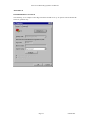
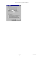
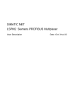
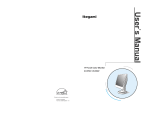
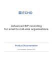
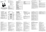
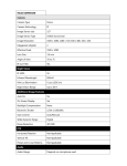
Sense
Box
VOICE RECORDING SYSTEM
ISDN PRI / BRI / Analog SUB-SYSTEM
ISDN2, ISDN30
Sense Box USER MANUAL
Sense Voice Recording System User Manual
TABLE OF CONTENTS
1.
STATUTORY INFORMATION .............................................................................................. 3
1.1
1.2
1.3
SAFETY WARNING ...................................................................................................................... 3
SAFETY EXTRA LOW VOLTAGE AND TELECOM NETWORK VOLTAGE PORTS .................................. 3
CONFORMANCE .......................................................................................................................... 3
2.
ENVIRONMENTAL CONDITIONS ....................................................................................... 3
3.
POWER ..................................................................................................................................... 3
3.1
3.2
POWER CONSUMPTION ................................................................................................................ 3
EXTERNAL POWER SUPPLY RATING ............................................................................................. 4
4.
MANUFACTURERS DETAILS ............................................................................................... 4
5.
PRODUCT DESCRIPTION ..................................................................................................... 5
5.1
5.2
ISDN ......................................................................................................................................... 5
ANALOGUE ................................................................................................................................ 5
6.
INTERFACE PORTS DESCRIPTION .................................................................................... 5
6.1
6.2
6.2.1
6.2.2
6.3
6.4
SERIAL PORT .............................................................................................................................. 6
ISDN2 BRI PORTS ..................................................................................................................... 6
ISDN2 BRI TE (IN) Ports........................................................................................................ 8
ISDN BRI NT (OUT) Port ....................................................................................................... 8
ISDN PRI PORTS........................................................................................................................ 8
POWER-IN .................................................................................................................................. 9
7.
INSTALLATION GUIDES ..................................................................................................... 10
8.
LIGHT EMITTING DIODES (LEDS) ................................................................................... 11
8.1 NORMAL OPERATION MODE...................................................................................................... 11
8.2 BOOT SEQUENCE ...................................................................................................................... 11
8.2.1 SB LED Indications .............................................................................................................. 11
FIGURES
FIGURE 1 ISDN2 SB - FRONT PANEL ........................................................................................................... 5
FIGURE 2 ISDN30 SB FRONT PANEL ........................................................................................................... 6
FIGURE 3 ISDN2 / ISDN30 SB - BACK PANEL ............................................................................................. 6
FIGURE 4 HMI CONNECTOR PIN OUT .......................................................................................................... 6
FIGURE 5 ISDN2 BRI TE CONNECTOR PIN OUT .......................................................................................... 8
FIGURE 6 ISDN BRI NT CONNECTOR PIN OUT ............................................................................................ 8
FIGURE 7 ISDN30 PRI TE CONNECTOR PIN OUT ......................................................................................... 8
FIGURE 8 ISDN30 PRI NT CONNECTOR PIN OUT......................................................................................... 8
FIGURE 9 POWER CONNECTORS PIN OUT ..................................................................................................... 9
FIGURE 10 ISDN2 SB INSTALLATION ........................................................................................................ 10
FIGURE 11 ISDN30 SB INSTALLATION ...................................................................................................... 10
Page 2
um049-04w
Sense Voice Recording System User Manual
1. STATUTORY INFORMATION
This document describes usage of the Retell Sense Call Recording Box (Aka Sense Box or SB).
1.1 Safety Warning
This apparatus contains no user serviceable parts
If the mains adapter shows signs of damage or malfunction immediately stop using the
adapter (disconnect it from the mains if applicable) and contact the supplier for repair or
replacement
This apparatus does not contain a designated mains disconnect device. To disconnect this
device from mains power, extract the power supply from the power outlet.
Do not expose the unit or the mains adapter to rain or moisture.
Do not operate in the proximity of water
Avoid using the product during an electrical storm. There is remote risk of electric shock
from lighting
Caution – To reduce the risk of fire, use only No.26 AWG or larger for the
telecommunication line cords
1.2 Safety Extra Low Voltage and Telecom Network Voltage Ports
Port Descriptions
ISDN Terminal Equipment (TE) ports
ISDN Network Termination (NT) ports
Analogue User / Network ports
Human Machine Interface (HMI) port
USB ports
Power-In
Port Declaration
TNV-1
TNV-1
TNV-3
SELV
SELV
SELV
All TNV-1 ports are user ports where the normal operating voltages do not exceed the limits for a
SELV circuit. Accessible ports declared as SELV accessory ports are solely for the connection of
accessories that do not use or generate voltages greater than that defined for a SELV circuit (42.4V
peak AC or 60V DC).
1.3 Conformance
The SB unit conforms to the following standard:
- EN60950
- EN41003
- EN55022 (Class B)
2. ENVIRONMENTAL CONDITIONS
Operation Temperature
Storage Temperature
Humidity
Operating Atmospheric Pressure
Weight
Dimensions
: 0°C to 40°C
: -20°C to 70°C
: 5% to 95% non-condensing
: 86KPa to 106KPa
: 1 Kg (max)
: 146mm x 225mm x 41mm (WxDxH)
3. POWER
3.1 Power Consumption
Power Input
: +5V DC
Max. Power Consumption
: 2.8A
Typ. Power Consumption (ISDN30): 494mA
Page 3
um049-04w
Sense Voice Recording System User Manual
Typ. Power Consumption (ISDN2) : 719mA
3.2 External Power Supply Rating
Input Voltage
Output Voltage
Output Current (ISDN2 & ISDN 30)
Output Current (Analogue)
: 90 – 264VAC 50/60Hz
: +5VDC
: 2.8A
: 4A
4. MANUFACTURERS DETAILS
Retell Limited
53 Thames Street,
Sunbury on Thames,
Middlesex TW16 5QH
England
United Kingdom
Page 4
um049-04w
Sense Voice Recording System User Manual
5. PRODUCT DESCRIPTION
This document describes both the Retell ISDN30 and ISDN2 communication systems known as Sense
Box (SB).
Both ISDN30 and ISDN2 systems are free standing mains powered devices and require a +5V DC
power input. The unit is shipped with an approved external Universal Power Supply Unit (PSU).
5.1 ISDN
The products provide interfaces to both the ISDN PSTN (as Terminal Equipment, TE) as well as
Customer Premise Equipment (CPE) normally represented by an ISDN Digital PBX (as a Network
Terminal, NT). The products operate as semi-passive devices monitoring all calls both to and from
the PBX. The SB captures call signaling data as well as full-duplex voice data and passes this to a
host PC through a connecting USB port. Third party software post-processes the received call
information and related voice data and archives it to the PC disk for any subsequent analysis
The ISDN2 SB supports four ISDN Basic Rate Interface (BRI) TE and NT ports and can handle up-to
eight simultaneous ISDN calls. The ISDN30 SB provides a single TE and NT port supporting a full
30 ISDN channels (calls) when in ISDN Primary Rate Interface (PRI) E1 mode.
A USB 2.0 connection is available on the rear of the SB.
A serial port is available for management purposes and can be connected directly via a serial port of a
Personal Computer.
5.2 Analogue
The product provides interfaces to both the Plain Old Telephone System (POTS) Public Switch
Telephone Network (PSTN) (as a Foreign eXchange Office – FXO) as well as Customer Premise
Equipment (CPE) normally represented by an analogue PBX (as a Foreign eXchange Station – FXS).
The product operates as semi-passive devices monitoring all calls both to and from the PBX. The CS
captures call signaling data as well as full-duplex voice data and passes this to a host PC through a
connecting USB port. PC software post-processes the received call information and related voice data
and saves it to the PC disk.
The Analogue SB supports eight FXO and FXS ports and can handle up-to eight simultaneous voice
calls.
6. INTERFACE PORTS DESCRIPTION
I SDN BRI ( N T)
U SB
I SDN BRI ( TE)
LEDs
HMI
Figure 1 ISDN2 SB - Front Panel
Page 5
um049-04w
Sense Voice Recording System User Manual
LEDs
U SB
I SDN PRI ( TE)
I SDN PRI ( N T)
HMI
Figure 2 ISDN30 SB Front Panel
* optional DC DIN 2.1mm
soc ket c onnec tor
Power-I n ( + 5V DC)
USB
Figure 3 ISDN2 / ISDN30 SB - Back Panel
6.1 Serial Port
The serial port, available via a 6 pin RJ11 modular jack connector, is used for system and
configuration management, and for diagnostic purposes. Its usage is restricted to Retell’s Authorized
personnel only. The serial port employs an industrial standard RS232 serial communication interface
and can be connected directly to the serial port of a personal computer (PC). The figure below shows
the pin-out of the HMI port. An RJ45 to DB9 converter is needed. Communication Software such as
PC-anywhere or Hyper-terminal should be used emulating a VT100 type, dumb terminal.
123456
Pin
2
3
5
6
Function
Data Terminal Ready (DTR)
Transmit Data (TD)
Signal Ground
Receive Data (RD)
Figure 4 HMI Connector Pin Out
6.2 ISDN2 BRI Ports
ISDN2 BRI ports are presented as “IN” and “OUT” port pair. Four pairs of BRI ports are provided
via a 4 by 2 stacked RJ45 modular jack. The “IN” port operates as a Terminal Equipment (TE) port
for connection to the ISDN Public Switch Telephone Network (PSTN) whilst the “OUT” port is the
Network Terminal (NT) port which can be connected to ISDN terminal equipment or PBX.
Page 6
um049-04w
Sense Voice Recording System User Manual
All the “IN” (TE) interface ports are presented on the bottom row of the stacked RJ45 modular jack
whilst all the “OUT” (NT) ports are available on the top row.
In the event of power outage to the ISDN2 SB, each of the port pair will be connected through to
allow downstream terminal equipment to continue to operate directly with the network.
Page 7
um049-04w
Sense Voice Recording System User Manual
6.2.1 ISDN2 BRI TE (IN) Ports
Four ISDN BRI TE ports are used for connection to the ISDN network. The TE ports are presented
on the bottom row of a 4 by 2 stacked RJ45 modular jack. The ISDN2 SB does not consume power
from the ISDN network from either Restricted or Normal Power Source 1 (PS1) but re-directs the
power onto the corresponding NT (OUT) port.
12345678
Pin
3
4
5
6
Function
TX+
RX+
RXTX-
Figure 5 ISDN2 BRI TE Connector Pin Out
6.2.2 ISDN BRI NT (OUT) Port
The ISDN2 BRI NT port provides an ISDN2 Basic Rate Interface (BRI) Network Termination (NT)
type interface for connection to an ISDN2 BRI terminal equipment or PABX. Four BRI NT ports are
available on the top row of the stacked RJ45 connector.
87654321
Pin
3
4
5
6
Function
RX+
TX+
TXRX-
Figure 6 ISDN BRI NT Connector Pin Out
6.3 ISDN PRI Ports
The ISDN30 SB provides only one pair of ISDN PRI “IN” and “OUT” interface port. Similar to the
ISDN2 SB, the “IN” port is the Terminal Equipment (TE) port and is used to connect to the ISDN
PSTN whilst the “OUT” port operates as a NT port providing a PBX connection.
In order to maintain service, the ISDN “IN” and “OUT” ports are connected together transparently
upon a power outage.
The following diagrams show the pin-out of the PRI interface ports.
12345678
Pin
1
2
4
5
Function
Rx Ring
Rx Tip
Tx Tip
Tx Ring
Figure 7 ISDN30 PRI TE Connector Pin Out
12345678
Pin
1
2
4
5
Function
Tx Ring
Tx Tip
Rx Tip
Rx Ring
Figure 8 ISDN30 PRI NT Connector Pin Out
Page 8
um049-04w
Sense Voice Recording System User Manual
6.4 Power-In
Both ISDN30 and ISDN2 SB are powered by a +5V DC supply. A 4-pin PC disk drive type connector
is used to connect to the external power adaptor. A DC DIN type connector is available as an optional
connector. It must be noted that the external PSU must only be connected to one of the two
connectors not both. Also the optional power connector must not be used to power other
equipment.
0 V + 5 VDC
0V
+ 5 VDC
Figure 9 Power Connectors Pin Out
Page 9
um049-04w
Sense Voice Recording System User Manual
7. INSTALLATION GUIDES
To PBX ISDN BRI TE Port
RJ45 to RJ45
c able
RJ45 to RJ45
c able
To PC (HUBS) USB
RJ11 to DB9
adaptor cable
USB Type A - B Cable
(2m Max.)
To PSTN ISDN BRI
To PC Serial Comms. Port
Figure 10 ISDN2 SB Installation
RJ45 to RJ45
cable
To PC (HUBS) USB
RJ11 to DB9
adaptor cable
USB Type A - B Cable
(2m Max.)
To PSTN To PBX ISDN
ISDN PRI PRI TE Port
To PC Serial
Com m s. Port
Figure 11 ISDN30 SB Installation
Page 10
um049-04w
Sense Voice Recording System User Manual
8. LIGHT EMITTING DIODES (LEDS)
Eight LEDs are used to indicate the operational status of the device. The “Power” LED indicates the
presence of the power to the unit and should remain on continuously during normal operation. The
function of the remaining seven LEDs depends upon the operating state of the SB. This is described
in more detail below.
8.1 Normal Operation Mode
The LED names are as seen from the front view.
B
D
A
C
IN
OUT
POWER
USB
8.2 Boot Sequence
When first powered up or after a system reset has been activated, the SB boots up. The LEDs should
light in green one after the other from the POWER-LED which remains green to IN, A, B, USB,
OUT, D, and D. The complete cycle should take around 15 seconds. If any led lights red or LED D
does not light green at the end of the boot sequence it is an indication of a major boot failure.
8.2.1 SB LED Indications
When the boot dequence is finished, the LEDs have
LED
Designatio
n
USB
IN
OUT
A
C
B
D
Color
Meaning
Off
Green
Red
Orange
Off
Green
Red
Orange
Off
Green
Red
Orange
Off
Green
Red
Orange
Off
Green
Red
Orange
Off
Green
Red
Orange
Off
Green
Green
Red
Orange
N/A (Not Applicable)
USB communication with the PC application is UP.
USB communication with the PC application is DOWN.
N/A
N/A
All telephone connections towards the PBX are UP.
All telephone connections towards the PBX are DOWN.
Some telephone connections towards the PBX are UP.
N/A
All telephone connections towards the PSTN are UP.
All telephone connections towards the PSTN are DOWN.
Some telephone connections towards the PSTN are UP.
There are no active inbound calls.
There is at least one active inbound call.
N/A
N/A
There are no active outbound calls.
There is at least one active outbound call.
N/A
N/A
Reserved
Reserved
Reserved
Reserved
Flashing Green: A firmware upload is in progress.
Steady Green: Firmware update succeeded.
Firmware update failed.
Firmware burning to flash RAM is in progress.
Page 11
um049-04w
Sense Voice Recording System User Manual
APPENDIX B
HYPERTERMINAL SETTINGS
The following is an example of how HyperTerminal should be set up to operate with the Retell SB
and is for guidance only.
Page 12
um049-04w
Sense Voice Recording System User Manual
Page 13
um049-04w
Sense Voice Recording System User Manual
Page 14
um049-04w