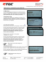
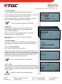
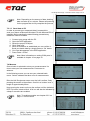
1
TQC HULL ROUGHNESS GAUGE DC9000 IMPORTANT! Before taking this instrument in use we strongly advise you to read this manual carefully. Operating Instructions for the HULL ROUGHNESS GAUGE MICROPROCESSOR CONTROLLED Hull Roughness Gauge – Instruction manual - Page 2 of 18 1 General ................................................................................................................................................. 4 1.1 Importance of operating manual...................................................................................................... 4 1.2 User-responsibility .......................................................................................................................... 4 1.3 Responsibility of personnel ............................................................................................................. 4 1.4 Dangers .......................................................................................................................................... 4 1.5 Designated purpose ........................................................................................................................ 4 1.6 Copyright ........................................................................................................................................ 4 1.7 Manufacturer's/Supplier's address .................................................................................................. 4 2 Safety Instructions .............................................................................................................................. 5 2.1 Meaning of Symbols ....................................................................................................................... 5 2.2 Availability of Safety Information ..................................................................................................... 5 2.3 Training of Personnel ...................................................................................................................... 5 2.4 Dangers from Electrical Energy....................................................................................................... 5 2.5 Points of Special Danger................................................................................................................. 5 2.6 Care, Maintenance, Repairs ........................................................................................................... 6 3 Transport and Storage ........................................................................................................................ 6 3.1 Packing ........................................................................................................................................... 6 3.2 User: Check on Receipt .................................................................................................................. 6 3.3 Reporting Transport Damage and Documentation .......................................................................... 6 3.4 Storage and Protective Measures when not in use ......................................................................... 6 4 Instrument Data ................................................................................................................................... 7 4.1 Name / Article ................................................................................................................................. 7 4.2 Scope of Supply .............................................................................................................................. 7 4.3 Technical Data ................................................................................................................................ 7 4.4 Dimensions and Weight .................................................................................................................. 7 4.5 Basic Unit ....................................................................................................................................... 7 5 Instrument controls and functions ..................................................................................................... 8 6 InStallation and preparations.............................................................................................................. 9 6.1 Batteries ......................................................................................................................................... 9 6.2 Connect your equipment ................................................................................................................. 9 6.3 Protect yourself and your equipment ............................................................................................... 9 6.4 Switching on your gauge ................................................................................................................. 9 7 Menu display information and operation ......................................................................................... 10 7.1 Main menu .................................................................................................................................... 10 7.2 Instrument setup ........................................................................................................................... 10 7.2.1 Setup time and Date .............................................................................................................. 10 7.2.2 Setup acoustics ...................................................................................................................... 10 7.2.3 Setup display ......................................................................................................................... 11 Hull Roughness Gauge – Instruction manual - Page 3 of 18 7.3 Memory......................................................................................................................................... 11 7.3.1 Batch options ......................................................................................................................... 11 7.4 Measure ........................................................................................................................................ 12 7.4.1 Accept series ......................................................................................................................... 13 7.4.2 Assign measurement-series to hull sections........................................................................... 13 8 Calibration .......................................................................................................................................... 14 8.1 Calibrate gauge ............................................................................................................................ 14 8.2 Procedure ..................................................................................................................................... 14 8.3 Program ref. std. (Please read this chapter carefully.) ................................................................... 15 9 Setting COM ports ............................................................................................................................. 16 9.1 COM ports 1,2,3 & 4 ..................................................................................................................... 16 9.2 COM ports 5 and above ................................................................................................................ 16 9.2.1 If COM port 1-4 are currently occupied................................................................................... 16 9.2.2 If COM ports 1-4 are currently not occupied ........................................................................... 17 10 HRG Windows application .............................................................................................................. 17 10.1 Installation................................................................................................................................... 17 10.2 Processing data with the HRG application .................................................................................. 17 11 Care and Maintenance ..................................................................................................................... 18 11.1 Inspection and Maintenance ....................................................................................................... 18 11.2 Disposal of Materials ................................................................................................................... 18 11.3 Customer Service ....................................................................................................................... 18 12 Disclaimer ........................................................................................................................................ 18 Hull Roughness Gauge – Instruction manual - Page 4 of 18 1 GENERAL 1.1 Importance of operating manual This manual is written in order to become familiar with all the functions and possible applications of the instrument. It contains important instructions about how to use the instrument safely and economically; according to the purpose designated. Following these instructions is not only essential to avoid risks. It also reduces repair costs and down-time and increases the products reliability and service-life. Anyone who works with the instrument should follow the instructions in this manual, particularly the safety related instructions. Additionally local rules and regulations relating to environmental safety and accident prevention should be observed. 1.2 User-responsibility The user should a) only allow persons to work with the instrument who are familiar with the general instructions on how to work safely and to prevent accidents. The use of the instrument should have been instructed duly The safety chapter and the warnings in this manual should have been read and understood; acknowledged as evidenced by their signature. b) regularly check the safety-awareness of personnel at work. 1.3 Responsibility of personnel Before commencing work anyone appointed to work with the instrument should pay attention to the general regulations relating to working safety and accident prevention. The safety chapter and the warnings in this manual should have been read and understood; acknowledged as evidenced by their signature. 1.4 Dangers This instrument has been designed and constructed in accordance with state-of-the-art technology and the acknowledged safety regulations. Nevertheless, working with the instrument may cause danger to the life and health of the operator or to others, or damage to the instrument or other property. Therefore the instrument should only be used for its designated purpose, and in a perfect technical condition. Any defect that could have a negative effect on safety should be repaired immediately. 1.5 Designated purpose The TQC Hull Roughness Gauge is exclusively designed to perform roughness tests on painted and coated or blasted surfaces as described within the specifications. Other applications constitute improper use. TQC will not be held liable for damage resulting from improper use. Designated purpose also includes properly observing all instructions in the operation manual, and adherence to inspection and maintenance schedules. 1.6 Copyright The copyright of this operating manual remains with TQC. This operating manual is intended solely for the user and his personnel. Its instructions and guidelines may not be duplicated, circulated or otherwise passed on to others, neither fully, nor partly. Infringement of these restrictions may lead to legal action may be taken if this restrictions are infringed upon. 1.7 Manufacturer's/Supplier's address TQC – Molenbaan 19, 2908 LL Capelle aan den IJssel - The Netherlands, T +31(0)10 7900100, F +31 (0)10 7900 129 Hull Roughness Gauge – Instruction manual - Page 5 of 18 2 SAFETY INSTRUCTIONS 2.1 Meaning of Symbols The following symbols for dangers are used in this instruction manual. Symbol Explanation Possible immediate danger to the life or health of personnel Warning If this guideline is not noted it can lead to severe danger to health, up to fatal injury A dangerous situation could be caused Non observance of this guideline can lead to injury or to damage to equipment. Special tips and particular information Guidelines to make optimal use of the instrument. Danger Warning 2.2 Availability of Safety Information The instruction manual should be kept at the place where the instrument operates. In addition to the information contained in the instruction manual, general and local regulations for accident prevention and environmental protection shall be kept available and observed. Always ensure all guidelines in respect of safety and dangers on the instrument are in readable condition. In case of danger the instrument has to be switched off by means of the emergency-button on the front of the instrument. Then eliminate danger. 2.3 Training of Personnel Anyone who operates the instrument should be trained properly. It has to be clear who has which responsibility regarding commissioning, set-up of maintenance and repairs, installation, and operation. Anyone who hasn’t finished training should be supervised by an experienced person while working with the instrument. 2.4 Dangers from Electrical Energy Work on the electrical supply may only be done by a qualified electrician. The electrical equipment of the instrument must be checked regularly. Loose connections and cable damaged by heat must be corrected immediately. If any work is to be done on parts connected to a voltage supply, a second person must be present to switch off the main switch if necessary. 2.5 Points of Special Danger There are some special points of danger: Always use supplied neck-strap to free your hands while working on scaffolds or platforms Hull Roughness Gauge – Instruction manual - Page 6 of 18 2.6 Care, Maintenance, Repairs Maintenance and inspection should be carried out at the correct intervals Operating personnel should be informed before starting with maintenance or repair work Do not open the instrument. In case of malfunction always consult the manufacturer. 2.7 Modifications to the Equipment Any modifications or additions or alterations to the instrument may solely be made with permission from the manufacturer. All measures involving modifications require written confirmation of approval from TQC Instruments which are not in fault-free condition must immediately be switched off Only use replacement parts from the original supplier. Parts used from other sources aren’t guaranteed to take the loading and meet the safety requirements. 2.8 Cleaning of the Instrument and Disposal of Materials When in use it is not always possible to avoid some spill of paint on the work surface. Try to keep the instrument as clean as possible to prevent distortions of functions. To clean the instrument properly use a suitable solvent to dispose remains of paint or ink. Wear gloves during cleaning; Don’t spill an overdose of solvent during cleaning. Cleaning materials must always be used and disposed of correctly. 3 TRANSPORT AND STORAGE 3.1 Packing Please take note of pictorial symbols on the packing. 3.2 User: Check on Receipt Check packing for damage After unpacking check complete supply. 3.3 Reporting Transport Damage and Documentation Any damage should be documented as accurately as possible (possibly photographed) and reported to the relevant insurers or, in the case of sales "delivered to customers works", to the supplier. 3.4 Storage and Protective Measures when not in use The instrument must be stored in a dry place at a temperature between 10 - 40°C. Store instrument in the original packing if possible. Hull Roughness Gauge – Instruction manual - Page 7 of 18 4 INSTRUMENT DATA 4.1 Name / Article DC9000 TQC Hull Roughness Gauge – Microprocessor Controlled Hull Roughness Gauge. 4.2 Scope of Supply TQC Hull Roughness Control unit with neck-strap TQC Hull Roughness Sensor TQC Hull Roughness Sensor Cable DC9015 Calibration plate USB thumb drive with software USB connection cable for PC 4 x AA batteries included 4.3 Technical Data Memory capacity: Power Supply: Display: Interface: . 4.4 Dimensions and Weight Sensor Depth: Sensor Width: Sensor Height: Sensor weight: 4000 series of measurements Batteries, 4 x AA batteries LCD 80mm, illuminated Menu driven interface with 4-way directional push button Control unit Depth: Control unit Width: Control unit Height: Control unit weight: 200 mm 115 mm 40 mm approx. 350 g 4.5 Basic Unit Power Supply: Display: Safety: Interface: Batteries, 4 x AA batteries ( included ) LCD 80mm, illuminated Neck-strap Menu driven interface with 4-way directional push button 205 mm 80 mm 40 mm approx. 630 g Hull Roughness Gauge – Instruction manual - Page 8 of 18 5 INSTRUMENT CONTROLS AND FUNCTIONS 2 3 1 13 5 8 10 9 11 12 6 4 7 1. Hull Roughness sensor 2. Sensor cable attachment 3. Soft rubber non-slip wheels 4. Status indication / warning lights 5. Neck-strap to securely carry your gauge 6. Hull Roughness Control unit 7. Hull Roughness Sensor cable 8 Illuminated LCD 9. 4-way directional push button 10. Indicating LED for ‘Measure’ 11. Indicating LED for ‘Full series’ 12. Indicating warning LED for ‘High Speed’ 13. Hull Roughness Surface profile probe 14. DC9015 Calibration plate 14 Hull Roughness Gauge – Instruction manual - Page 9 of 18 6 INSTALLATION AND PREPARATIONS Carefully unpack the apparatus and the accessories and check complete supply. Please assemble your equipment before climbing upon scaffolds or platforms. Use supplied neckstrap to securely attach the apparatus and prevent possible damage from falling. 6.1 Batteries Your gauge runs on standard alkaline AA batteries. These batteries are easily available worldwide by local suppliers. The Hull Roughness gauge needs 4 AA batteries to operate. Note: Only use standard AA alkaline batteries to ensure proper functioning of your gauge. The use of rechargeable batteries is not recommended because they tend to suffer from to big voltage drops possibly influencing measuring results. Your gauge is supplied with a set of 4 AA batteries. 6.2 Connect your equipment Connect the sensor and control unit with the supplied sensor cable. The direction of the cable is not important, both sides of the cable are identical male plugs and interchangeable. Firmly press the plugs in corresponding connectors on both the sensor and control unit. The plug is properly connected and locked into place when you hear / feel a click. Note: To release the sensor cable from both sensor and control unit push the little fuse button beside both connectors. The plug should be able to eject from the connector without the use of excessive force. 6.3 Protect yourself and your equipment Please assemble your equipment before climbing upon scaffolds, cherry pickers or platforms. Use supplied neck-strap to securely attach the apparatus. Using the neck-strap is for your own safety and allows you to free one hand while it also prevents your gauge from falling. 6.4 Switching on your gauge A single press on the 4-way directional push button will present you with the start-up screen. You are welcomed by our TQC logo and the current firmware version is displayed. Hull Roughness Gauge – Instruction manual - Page 10 of 18 7 MENU DISPLAY INFORMATION AND OPERATION 7.1 Main menu The TQC Hull Roughness Gauge has an advanced menu structure. The Main Menu allows the user to access all the features available. Use arrow buttons to navigate through menu options and press ‘Ok’ to confirm your choice. 7.2 Instrument setup The setup menu allows you to calibrate your gauge. The calibrate procedure is explained in chapter 8 on page 14 of this manual. The other options need to be set once before first time use of your gauge. 7.2.1 Setup time and Date Please set the correct time in your gauge. ( 24 hour format). Use the 4-way directional push button to select the digit you would like to change. Confirm your selection with a single press on the ‘Ok’ button. Use up- and down buttons till the desired digit is displayed. Confirm your selection with a single press on the ‘Ok’ button and Continue with the next digit. Please set the correct date in your gauge. ( DD/MM/YYYY format ) Use the 4-way directional push button to select the digit you would like to change. Confirm your selection with a single press on the ‘Ok’ button. Use up- and down buttons till the desired digit is displayed. Confirm your selection with a single press on the ‘Ok’ button and Continue with the next digit. Note: Your time and date settings are AutoSaved. 7.2.2 Setup acoustics The sound level can be adjusted to your needs. You can set the gauge to either: Signals off / Low volume and high volume. Use up- and down buttons to select the desired acoustics level and confirm with a single press on the ‘Ok’ button. Note: Your acoustics settings are AutoSaved. Hull Roughness Gauge – Instruction manual - Page 11 of 18 7.2.3 Setup display You can change both backlight and contrast settings. Use up- and down buttons to select either ‘Backlight’ or ‘Contrast’ and confirm with a single press on the ‘Ok’ button Use left- and right buttons to adjust the ‘Backlight’ or ‘Contrast’ level. Confirm with a single press on the ‘Ok’ button. Note: Your display settings are AutoSaved. 7.3 Memory Measurements can be stored in different batches. The Hull Roughness Gauge can store up to 8 batches that can be named individually. Click the ‘Ok’ button once to select a batch. A checkmark will appear before the selected batch. Click the ‘Ok’ button once more in order to access the batch options. 7.3.1 Batch options Allows you to either name/rename batches, delete batches and send batches to a personal computer for further data analysis. 7.3.1.1 Renaming batches Click ‘Rename’ to give the batch a name. Use the 4-way directional push button to select the character you would like to change. Confirm your selection with a single press on the ‘Ok’ button. Use up- and down buttons till the desired character is displayed. Confirm your selection with a single press on ‘Ok’ button and Continue with the next character. Note: Your batch names are AutoSaved. 7.3.1.2 Clear Clear allows you to erase all measurements of the selected batch. A single press on the ‘Ok’ button will prompt you with a confirmation screen. Confirm the clearing of all batch data with a single press on the ‘Ok’ button. Warning: Your data is permanently erased! Hull Roughness Gauge – Instruction manual - Page 12 of 18 Note: Depending on the amount of data, deleting data can take up to a minute. Please wait patiently for the progress bar to fully complete the process. 7.3.1.3 Send data to PC In order to process your measured data it is essential to send your data to a Microsoft Windows PC with Microsoft Excel installed. Before sending the data following precautionary measures need to be taken: 1. 2. 3. 4. 5. Connect your gauge with the PC Open the HRG application Select the proper COM port Click ‘Open port’ When a connection is established you can confirm to Send your batch data by a single press on ‘Ok’ button. 6. Your raw data appears in the HRG application 7. Press ‘Data -> Excel’ Note: More information on setting COM ports is available in chapter 10 on page 16. 7.4 Measure Once a batch is selected to store your measurements it is time to start your first measurements. Press start to advance. In the following screen you can see your selected batch name. ‘Series’ indicates the taken runs of measurements. Role the Hull Roughness sensor over the hull’s surface, firmly pressing the sensor to the surface. One full run is taken over a length of approximately 90cm. Keep moving the sensor unit over the surface until the indication LED ‘Full series’ starts to blink. A full run will also be indicated by a beep if acoustics are enabled. Note: To enable acoustics see chapter 8.2.2 on page 11 of this manual. Hull Roughness Gauge – Instruction manual - Page 13 of 18 7.4.1 Accept series After each measurement the Mean Hull Roughness (MHR) of the last series and the Average Hull Roughness (AHR) of all series is displayed. If you encounter measurement errors or want to measure the last Hull section once again, simply press ‘Back’ and redo your measurement. If you agree with the result you can click ‘Accept’. In the next step you can allocate your series of measurements to the proper hull section. 7.4.2 Assign measurement-series to hull sections After accepting the measurement results each series of measurements can be assigned to a specific hull section. Either a starboard or portside image of the ship is displayed. Use the 4-way directional push button to select the corresponding hull section and click ‘Ok’ to assign your series to this hull section. To switch between starboard and portside images select: ‘SB < - > PS‘ (Starboard vs. Portside) Press ‘Ok’ button to switch the displayed image. Already measured sections are indicated with a small square. Once a hull section has been measured you could overwrite the section data. Select the square marked section and click the ‘Ok’ button once to overwrite older measurements. Note: Overwrites are permanent, you are not asked or warned with a confirmation screen. . Hull Roughness Gauge – Instruction manual - Page 14 of 18 8 CALIBRATION To ensure proper measurements it is required to regularly calibrate your gauge. Note: For best calibration results allow your equipment to adjust to ambient temperature for about ten minutes. 8.1 Calibrate gauge Select from menu : 1. Instrument setup 2. Calibrate 3. Calibrate gauge Position the sensor unit as displayed in the image below: (Move the sensor unit back and forth a bit to assure proper alignment with the calibration plate.) 8.2 Procedure 4. 5. 6. 7. 8. 9. Click ‘Ok’ to start the calibration procedure Align the rear wheel with the ‘0 μm’ on the calibration plate. Press ‘Ok’.* Align the rear wheel with the ‘500 μm’ on the calibration plate. Press ‘Ok’.* Align the rear wheel with the ‘1500 μm’ on the calibration plate. Press ‘Ok’.* Align the rear wheel with the ‘2500 μm’ on the calibration plate. Press ‘Ok’.* Confirm your new calibration by pressing ‘Synchronize’. *Note: If your measured values deviate a lot from the reference point values, repeating the complete calibration process multiple times will improve both accuracy and calibration. Example: During step 5 of the calibration procedure the displayed ‘Ref.’ value (0000) and the measured ‘Gauge’ value on the control unit can deviate a lot depending on how well the gauge has been calibrated in the past. If your gauge has never been calibrated the measured value can deviate extremely. * Whatever the measured value might be, just ignore it and Press ‘Ok’. You are adjusting the gauge now. Literally you tell the gauge: “What you have measured is 0 μm!” The same goes for step 6,7 & 8 of the calibration procedure. Repeating the calibration process once more should lessen the deviation of Hull Roughness Gauge – Instruction manual - Page 15 of 18 readings till the point that the measured value is well within the specified accuracy of the gauge. (+/- 5 microns or <2%, whichever is greater). Repeating the calibration process will confirm and assure you that the measured values are accurate. From our experience we can tell that a well calibrated gauge often has an accuracy way beyond our given specifications of +/- 5 microns or <2%, whichever is greater. Many times the gauge is spot on! Repeating the calibration procedure ( Steps 4-9 ) 2 or 3 times is sufficient. 8.3 Program ref. std. (Please read this chapter carefully.) This advanced feature should only be used if you have equipment to exactly measure your calibration plate or possess a calibration plate accompanied with a valid calibration certificate. (TQC offers calibration services and is able to supply your gauge with a fully traceable calibration certificate for the calibration plate. Since gauge calibrations itself can easily be altered we do not recommend to calibrate the actual gauge.) This feature should only be changed if the reference standard deviates from the standard 0000, 0500, 1500 & 2500 micron reference. Your calibration report might state that the 500 μm reference point actually measures 498 μm. In the ‘program ref. std.’ option you can adjust the gauge for this deviation. Select: 1. Instrument setup 2. Calibrate 3. Program ref. std. Select [ 0500 ] and click ‘Ok’. ( [ 0500 ] starts to blink) Use Up/Down keys to adjust the value to the value stated in your calibration certificate, 498 μm in our example and press ‘Ok’. The same goes for [ 1500 ] & [ 2500 ] Finally confirm your adjustments to save the made alterations. Note: If you perform a new calibration of the gauge you will notice that the ‘Ref.’ values have changed according to your made adjustments. Hull Roughness Gauge – Instruction manual - Page 16 of 18 9 SETTING COM PORTS The computer system will automatically assign a COM port number to the gauge. Please check Windows ‘Device Manager’ to learn the assigned COM port. Tip: Windows shortcut to ‘Device Manager’: Windows key + Pause key Unfold ‘Ports (COM & LPT)’. The gauge is recognized as: ‘USB Serial Port (COM…)’ If you have failed to recognize the Hull Roughness Gauge within Windows Device Manager reconnect your gauge and pay close attention to the list in Windows Device Manager as the gauge will reappear here. 9.1 COM ports 1,2,3 & 4 Please set HRG software COM port settings to the assigned COM port. Currently only 4 COM ports are available. If you gauge is recognized as COM 5 or higher please contact your IT department for a workaround or continue reading next chapter ‘10.2 COM ports 5 and above’. 9.2 COM ports 5 and above Your gauge has an assigned COM port number of 5 or higher since 1-4 are in use or have been in use by other computer devices in the past. 9.2.1 If COM port 1-4 are currently occupied Move one of your devices connected to COM ports 1,2,3 or 4 to port number 5 or above: - Select the device to move in ‘Device Manager’ and right click your mouse. - Subsequently select Properties / Port settings tab / Advanced - Edit current port number and confirm any changes you have made. Set current COM (1-4) to 5 or higher. Subsequently repeat previous steps to move your gauge to either COM ports 1,2,3 or 4. Hull Roughness Gauge – Instruction manual - Page 17 of 18 9.2.2 If COM ports 1-4 are currently not occupied If COM ports 1-4 are currently not in use but the Hull Roughness Gauge has an assigned COM port number of 5 or higher: - Select the Hull Roughness Gauge in ‘Device Manager’ and right click your mouse. Subsequently select Properties / Port settings tab / Advanced Move your gauge to either COM ports 1,2,3 or 4 and confirm any changes you have made. 10 HRG WINDOWS APPLICATION 10.1 Installation The HRG application supplied on the USB thumb drive does not require any installation. Double click the HRG V1.01 file to launch the application. Your Windows installation might prompt you with a "The publisher could not be verified" message. Please click ‘Run’ to continue. 10.2 Processing data with the HRG application This application functions as an interface between your Hull Roughness Gauge and the Microsoft Excel Survey Report. - Please select the proper COM port (chapter 10 of this manual) and click ‘Open Port’. Use your gauge to select a batch and send it to the HRG application (chapter 8.3.2.2) Click ‘Data -> Excel’ to generate your Hull Roughness Survey Report. Hull Roughness Gauge – Instruction manual - Page 18 of 18 11 CARE AND MAINTENANCE 11.1 Inspection and Maintenance Though robust in design, this instrument is precision-machined. Never drop it. Always clean the instrument after use. Clean the instrument using a soft dry cloth. Never clean the instrument by any mechanical means such as a wire brush / abrasive paper. This may cause, just like aggressive cleaning agents, permanent damage. Do not use compressed air to clean the instrument. Generally the TQC Hull Roughness Gauge does not require any maintenance. Make sure that no paint or other liquids are spilled on the electronics or left in the holes. Warning 11.2 Disposal of Materials Disposal of materials used in the operation of the instrument or for auxiliary functions and exchanged items should be dealt with safely and in a manner that will not harm the environment. Follow the local regulations. 11.3 Customer Service Customer service is provided on request by TQC – Molenbaan 19, 2908 LL Capelle aan den IJssel - The Netherlands, T +31(0)10 7900100, F +31 (0)10 7900 129 or by local representatives. 12 DISCLAIMER The right of technical modifications is reserved. The information given in this manual is not intended to be exhaustive and any person using the product for any purpose other than that specifically recommended in this manual without first obtaining written confirmation from us as to the suitability of the product for the intended purpose does so at his own risk. Whilst we endeavour to ensure that all advice we give about the product (whether in this manual or otherwise) is correct we have no control over either the quality or condition of the product or the many factors affecting the use and application of the product. Therefore, unless we specifically agree in writing to do so, we do not accept any liability whatsoever or howsoever arising for the performance of the product or for any loss or damage (other than death or personal injury resulting from our negligence) arising out of the use of the product. The information contained in this manual is liable to modification from time to time in the light of experience and our policy of continuous product development.