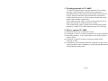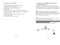
1
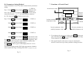
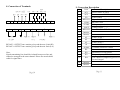
Tension Controller – Feed-back system
TC-608N Control Panel
In the form of a Load Cell
USER’S MANUAL
TENSION CONTROLLER
TENSION
○ RUN
○ PRG
○ ERR
MODE
CH
TENSION SET
SET
TC-608N
October, 2005
Prelude
Thank you for applying our TC-608N Tension Controller –
Feedback system (abb. 608N) to your machinery equipment. Since
the control systems renew quickly with time, usually the former
customers have to acquaint all complicate parameters and programs
very well before running each new system. We hear the voice from
the customers’ mind and notice the aspirations of them, so we
develop the 608N series with strong function but simple operation.
Please read this manual carefully before running 608. Also please
keep this manual properly in order to arrange electric wires, set up
parameters and trouble-shooting if required in the future.
☆ CAUTION:
(1) Forbid to arrange the electric wires or unload the connector of
608N when electricity is supplying.
(2) Terminals 11~14 are reserved for signals feedback and output,
please do not connect with other usages.
(3) Forbid to connect Terminals 6 (+) and 7 (-) with AC power
source or wrong voltage.
(4) Please do not take apart the housing of controller, and do not
test voltage resistance on components of controller inside,
either.
(5) The parameters of 608N have been set up properly by factory,
except on particular control requirements, it needs not to re-set
any.
(6) Assure power source to be AC 220V ± 10% and connected
with Terminals 1 and 2.
(7) Assure tension signals output to be connected with Terminals
11 ~ 14.
Page 1
Contents
1.
2.
3.
4.
5.
6.
7.
8.
9.
10.
11.
12.
13.
Prelude.................. Page 3
Working principle of TC-608N....... Page 3
How to operate TC-608N.......... Page 3
Characteristics of TC-608N......... Page 4
Flow-chart of TC-608N Application... Page 5
Working diagram.............. Page 6
(1)Material Put-in.................. Page 6
(2)Material Roll-up.................. Page 7
Electrical specifications......... Page 8
External dimensions................ Page 9
Functions of Control Panel.......... Page 10
Connection of Terminals.......... Page 11
Parameters setting method......... Page 12
Parameters table............. Page 13
Explanation of Parameters....... Page 14
Tension Detection ZERO SET and Tension Page 17
Rectification(SPAN)
Page 2
1. Working principle of TC-608N
TC-608N is a high accuracy tension controller. The working
principle of this controller is based on the comparative
calculation between the required value and the actual value of
tension, then the controller will automatically command to
modify the brake power or roll-up torque to match the actual
tensile value with the required one.
*The required tensile value is set up by the operator at site to
decide the tension for material put-in or roll-up.
*The actual tensile value is gotten from measuring the actual
tension by LOAD CELL when material is put in or rolled up.
2. How to operate TC-608N
(1) Terminals 15 and 16 are contacts for start.
(2) Terminals 15 and 17 are short-circuited to set up the parameters
(3) Secondly push Δ or ∇ on Control Panel to set up the required
tension value.
(4) Terminals 15 and 18 are short-circuited to break off the
function of PID.
(5) Compulsory second integral function: terminals 15 and 19 are
short-circuited to enter compulsory second integral function for
modifying the setting value.
Page 3
3. Characteristics of TC-608N
1.
2.
3.
4.
5.
6.
7.
High accuracy and reliability with reasonable price.
Intelligent design with easy operation.
Changeover units of tensile value: kg / N / LB.
Inbuilt signal amplifier of Tension detector.
Digital design.
Dual displays for the required and the actual value of tension.
Multi separate power sources built inside, with signals input
isolated by photo coupling in order to get the best
anti-interfering effect.
8. Unique anti-interference design, available for positive or
negative signal output.
9. Function of memory as power failure.
13. Tension Detection ZERO SET and Tension
Rectification(SPAN)
When tension detector is mounted on the machine,a tension
transmitting is generally put in .The weight of the device has to
betaken into account. As a result, before using TC-608N,structural
zero set and tension rectifying procedures have to be performed.
Step 1 :
When tension detector is mounted on the machine, first of all,
please clear all objects on the detector device. Getting into
parameter method and read the value of red LED(Tension feedback
value),then make the setting value of Pr15 to be Zero, which is
called “Tension zero set” procedures.
Step 2 :
Please placing tension rectifying weights on the device and read
the value of red LED(Tension feedback value),
Caution: Please make sure the way of bring pressure to be the same
as the material processing direction.
Then make Pr16 value equal to rectifying weights. Repeat Step1
and Step2 to finish “Tension Rectification” procedures.
Page 4
Page 17
Pr13
Lower limit for feedback of Tension
4. TC-608N Working diagram
(1)Material Put-in
Pr14
Max. voltage output for TC608N
Pr15
Zero point setting for tension detector
Pr16
K value from tension detector
Pr17
Decimal point position for Tension display value
Pr18
Upper display content
1. Tension feedback value
AIR
BRAKES
EP852
POWDER
BRAKES
Load
Cell
VA816
2. Voltage output
Pr19
INV.
Ave. time for Tension display(0.01~25.5 Sec.)
Pr20
Output method selections(Option : 0/1)
0 : active power(Motor)
1 : passive power(Brake)
Pr21
Initial output value of voltage
When executing TC-608N(Shortcut terminals 15 and
17) , there is a voltage output value.
TC608
Page 5
Page 16
(2)Material Roll-up
Pr07
First IK value(0.01~99.99 Sec.)。
Pr08
Second IK value(0.01~99.99 Sec.)。
Pr09
Deviation range for second IK. When the actual value is
under the range, TC608N will modify by First IK value;
if not (over tolerated range), TC608N will modify by
Second IK value.
Load
Cell
Pr10
Max. voltage range by integral modification:Limit
voltage output range, modified by integral value
INV.
DC
VA- 油壓馬達
INV. Driver 816 Driver
AMP
Pr11
Unwinding / winding module setting
0=unwinding module, material put-in
1=winding module, material roll-up
TC608
DC 0~10 V
Pr12
Page 6
Upper limit for feedback of Tension
Page 15
12. Description of Parameters
Pr01
Password: present at 1234 into parameters modifying
5. Electrical Specifications
Pr02
No-response range. When feedback value is in the
period of No-response range,TC-608N will not execute
Pr03
Startup deviation delay time(0.1~25.5 Sec.):
After starting, TC608 will stop for your setting time, then
restart to output voltage
Pr04
(P)ratio modification by percentage:000~100﹪。
Power Source
Power Consumption
Analog Tension Input
Control Output
Alarm Output x 2
Operating Temperature
Storage Temperature
Humidity
Weight
Pr05
Max. voltage range by ratio modification:Limit
AC 220V ± 10%, 50/60 Hz
15W max.
A/D 14Bit
D/A 12Bit
RELAY, 250VAC, 1A
0º~60ºC
-20º~70ºC
0~95%RH
1kg max.
voltage output range, modified by ratio value
Pr06
Startup value for executing integral function:
Under startup value, the function won·t be executed. On
the contrary, when actual value meet Startup value,
TC608N output First IK value for modification.
Page 14
Page 7
11.Parameters Table
Pr. No.
6. External Dimensions
100m/m
TENSION CONTROLLER
TENSION
100m/m
Pass-code
Irresponsive zone of Tension
Startup deviation delay time
Ratio modification value
Max. voltage modified by ratio value
Starting value for integral function
First IK value
8
Second IK value
12
13
Tolerated range for second IK value
Max. voltage modified by Integral value
0:material put-in
1:material roll-up
Upper limit for feedback signal
Lower limit for feedback signal
14
TENSION SET
9
10
MODE
SET
11
TC – 608N
160m/m
0000~9999
0000~999.9
0.1~25.5(S)
0 ~ 100﹪
0~10(V)
0000~99.99﹪
0.01~99.99 Sec.
0.01~99.99
Sec.
000 ~ 99.99
00.01 ~ 10.00
0.40
00.8
8.00
0
0000 ~ 9999
0000 ~ 9999
500.0
-12.3
Voltage output range
00.00 ~ 10.00
10.00
15
16
17
Zero point setting
Tension input “K"
decimal point position
-
-
0~2
adjustment
adjustment
1
18
Upper display content
1 : feedback value
2 : output voltage
1~2
1
00.1~25.5
1.5
0~1
0
0.00~10.00
02.00
20
21
Ave. time for Tension display
Output methods
0 : active power(Motor)
1 :passive power(Brake)
Initial output voltage
Panel opening: 92 x 92 m/m
Page 8
Factory
setting
1000
00.2
00.2
0.60
0.20
00.1
0.60
0~1
19
90m/m
Range
1
2
3
4
5
6
7
○ RUN
○ PRG
○ ERR
CH
Function
Page 13
10. Parameters Setting Method
7. Functions of Control Panel
Assure Terminals 15 and 17 are short-circuited before parameters
setting.
☼ PRG on
Step 1. Push MODE button, display 1234
parameter value
0001
parameter no.
Note: The pass-code of Parameter No. 1 must be 1234 (a fixed
value) Please push △ or ▽ on Control Panel to adjust to
be 1234, then push SET to display normal value.
Step 2. Push MODE button, display 1234
0001
☼ PRG on
Push MODE button, display
0100
0002
☼ PRG on
Push MODE button, display
.
.
.
Push MODE button, display
0005
0003
.
.
0000
0016
☼ PRG on
Actual tension value
TENSION CONTROLLER
TENSION
○ RUN
○ PRG
○ ERR
Confirm modification
of parameter value
MODE
TENSION SET
▲
▼
CH
Changeover of
Parameter No.
Decrease parameter value +
(modify parameter value)
☼ PRG on
Push MODE button, display 0030 Actual tensile value
0030 Required tension value
Push SET to confirm the value modification accomplished. Then
system goes back to operative mode. If need to modify other
parameters, just repeat the procedure above.
Push MODE on and on, green LED displays from 01~19 in a
circle.
In normal operating module, PRG lights up means the feedback
value is under the range of setting value (Pr02 : Irresponsive zone).
8. For setting up the parameters’ values, push MODE with correct
pass-code, then push SET for confirmation. The system will get
in the parameter setting procedure.
9. The required tensile value can be set up on control panel
directly. It needs not to get in the parameter setting procedure.
Page 9
Page 12
SET
TC-608N
Increase parameter value +
(modify parameter value)
Required
tension value
8. Connection of Terminals
9. Connection Description
PID
LOAD CELL
EX+ EX- SG+
9
10
1
SUPPLY
AC 220V
11
2
12
13
3
FG
Com
SG-
14
4
Start
Prg
Stop It2
。 。 。 。
。 。 。 。
15
16
5
RELAY 1 RELAY
COM
17
18
19
6
7
-
+
20
21
8
RELAY 2
OUTPUT
RELAY 1: OUTPUT once tension go beyond the max. limit (HI)
RELAY 2: OUTPUT once tension go beyond the min. limit (LO)
Note:
Signal transmitting line should be isolated from power line and
cannot be arranged in the same channel. Please use metal shield
cable for signal lines.
Page 10
Code
1
2
3
4
5
6
7
8
9
10
11
12
13
14
15
16
17
18
19
Item
AC1
AC2
FG
RELAY1
COM
VCOM
VOUT
RELAY2
Inactive
Inactive
AI
AI
AI
AI
ICOM
IP1
IP2
IP3
IP4
20
21
Inactive
Inactive
Description
Power source AC220V
Power source AC220V
Earth contact
Upper limit for RELAY
RELAY COM
Voltage output(-)
Voltage output(+)
Lower limit for RELAY
Load Cell EX+
Load Cell EX-
Load Cell SG+
Load Cell SG-
Common contact for control
Start contact
Parameters revised contact
Temporality stop PID function
The contact of compulsory process of
Second integral
Page 11