1
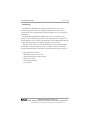
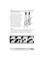
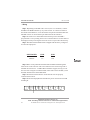
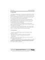
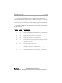
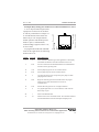
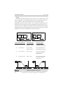
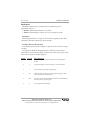
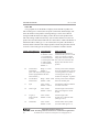
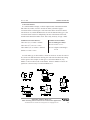
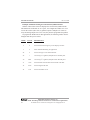
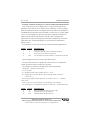
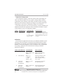
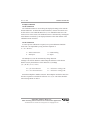
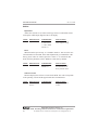
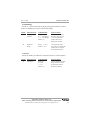
AUTOMATION
P R O D U C T S
G R O U P,
I N C.
Operator’s Manual
DCR-1005
and
DCR-1006
Rev. A4, 10/08
Doc. 9002664
Automation Products Group, Inc.
APG...Providing tailored solutions for measurement applications
Tel: 1/888/525-7300 • Fax: 1/435/753-7490 • www.apgsensors.com • E-mail: [email protected]
DCR-1005 and DCR-1006
Rev. A4, 10/08
Table of Contents
Warranty ......................................................................................... 3
Introducing ...................................................................................... 4
Understanding Ultrasonics ............................................................. 5
Installation ...................................................................................... 7
Wiring ............................................................................................ 10
Programming ................................................................................ 11
Error Indicators ............................................................................ 11
Programming Modes .................................................................... 12
Operation ................................................................................... 13
Filtering ..................................................................................... 14
Outputs ...................................................................................... 16
Applications ............................................................................... 21
Calibration ................................................................................. 26
Utilities ...................................................................................... 28
Quick Reference Sheet .................................................................. 30
Maintenance ................................................................................. 32
DCR Specifications ....................................................................... 33
DST Specifications ........................................................................ 34
Automation Products Group, Inc.
APG...Providing tailored solutions for measurement applications
2
Tel: 1/888/525-7300 • Fax: 1/435/753-7490 • www.apgsensors.com • [email protected]
Rev. A4, 10/08
DCR-1005 and DCR-1006
• Warranty and Warranty Restrictions
APG warrants its products to be free from defects of material and workmanship
and will, without charge, replace or repair any equipment found defective upon
inspection at its factory, provided the equipment has been returned,
transportation prepaid, within 24 months from date of shipment from factory.
THE FOREGOING WARRANTY IS IN LIEU OF AND EXCLUDES ALL OTHER
WARRANTIES NOT EXPRESSLY SET FORTH HEREIN, WHETHER
EXPRESSED OR IMPLIED BY OPERATION OF LAW OR OTHERWISE
INCLUDING BUT NOT LIMITED TO ANY IMPLIED WARRANTIES OF
MERCHANTABILITY OR FITNESS FOR A PARTICULAR PURPOSE.
No representation or warranty, express or implied, made by any sales
representative, distributor, or other agent or representative of APG which is not
specifically set forth herein shall be binding upon APG. APG shall not be liable
for any incidental or consequential damages, losses or expenses directly or
indirectly arising from the sale, handling, improper application or use of the
goods or from any other cause relating thereto and APG’s liability hereunder, in
any case, is expressly limited to the repair or replacement (at APG’s option) of
goods.
Warranty is specifically at the factory. Any on site service will be provided at
the sole expense of the Purchaser at standard field service rates.
All associated equipment must be protected by properly rated electronic/
electrical protection devices. APG shall not be liable for any damage due to
improper engineering or installation by the purchaser or third parties. Proper
installation, operation and maintenance of the product becomes the
responsibility of the user upon receipt of the product.
Returns and allowances must be authorized by APG in advance. APG will
assign a Return Material Authorization (RMA) number which must appear on
all related papers and the outside of the shipping carton. All returns are subject
to the final review by APG. Returns are subject to restocking charges as
determined by APG’s “Credit Return Policy”.
Automation Products Group, Inc.
APG...Providing tailored solutions for measurement applications
Tel: 1/888/525-7300 • Fax: 1/435/753-7490 • www.apgsensors.com • [email protected]
3
DCR-1005 and DCR-1006
Rev. A4, 10/08
• Introducing
The DCR-1005 and DCR-1006 controller with DST series sensors were
specifically designed to provide a rugged and reliable non-contact sensor
system that is easily programmed yet flexible enough to use in a wide range of
applications.
The DCR-1005 and DCR-1006 controllers have a 0.5 in. 4 character LCD
display to show readings and parameters. The controller can be configured to
monitor distance, level or volume. The DCR-1005 comes standard with four relay
outputs. The DCR-1006 also includes an isolated 4 - 20 mA output.
The DST series sensors are non-contact ultrasonic sensors which measure
the distance to a target through air. A list of available sensors can be found
under DST Specifications, found at the end of this manual starting on page 35.
Typical applications include:
• Monitoring water levels in a well
• Determining material volume in a tank
• Obstacle avoidance
• Product dimensioning
• Loop control
Automation Products Group, Inc.
APG...Providing tailored solutions for measurement applications
4
Tel: 1/888/525-7300 • Fax: 1/435/753-7490 • www.apgsensors.com • [email protected]
Rev. A4, 10/08
DCR-1005 and DCR-1006
• Understanding Ultrasonics
Ultrasonic sensors measure distance
using a transducer to send out ultrasonic
bursts. Each burst contains a series of 120 pulsed sound waves that emit in the
shape of a cone, reflect off the target,
and are received by the sensor. The time
required for the sound burst to travel to
and from the target is converted into a
distance measurement by the sensor.
Ultrasonic sensing is affected by
several factors including the target
surface, distance, size, and angle. The
following considerations will help ensure
the best possible target conditions.
low sensitivity
and
pulses
detection
area
high sensitivity
and
pulses
beam spread
Surface
The ideal target surface is hard and smooth and perpendicular to the face of
the transducer. This surface will reflect a greater amount of signal than a soft,
sound wave absorbent surface. A target with poor sound wave reflection
characteristics will reduce the operating distance of the sensor and decrease its
accuracy.
Automation Products Group, Inc.
APG...Providing tailored solutions for measurement applications
Tel: 1/888/525-7300 • Fax: 1/435/753-7490 • www.apgsensors.com • [email protected]
5
DCR-1005 and DCR-1006
Rev. A4, 10/08
Distance
The shorter the distance from the sensor to an object, the stronger the
returning echo will be. Therefore, as the distance increases, the object requires
better reflective characteristics to return a sufficient echo.
Size
A large object will have a greater surface area to reflect the signal than a
small one, therefore, a large target will be detected at a greater distance than a
small target. The surface area recognized as the target is generally the portion
closest to the sensor.
Angle
The inclination of the object's surface facing the ultrasonic sensor affects the
reflectivity of the object. The portion perpendicular to the sensor returns the
echo. If the entire surface is at a great enough angle, the signal will be reflected
away from the sensor and no echo will be detected. Generally a target at an
angle greater than 5 degrees off perpendicular will not be detected.
Environmental Conditions
Temperature, humidity, gases, dust, and pressure may also affect the sensor’s
performance. APG ultrasonic sensors automatically compensate for many of
these conditions. However, these conditions can degrade the sensor’s
performance enough it may be necessary to use a longer-range sensor than
normal conditions would require.
10 ft.
9 ft.
8 ft.
1 ft.
3 ft.
2 ft.
0.634'
Sensor
7 ft.
6 ft.
5 ft.
4 ft.
0.950'
1.267'
1.584'
1.901'
2.217'
2.534'
2.851'
3.168'
0.317'
Typical Beam Pattern of a Ceramic Transducer
at high sensitivity and power settings.
Automation Products Group, Inc.
APG...Providing tailored solutions for measurement applications
6
Tel: 1/888/525-7300 • Fax: 1/435/753-7490 • www.apgsensors.com • [email protected]
Rev. A4, 10/08
DCR-1005 and DCR-1006
• Installation
Installing the DCR
The DCR-1005 and DCR-1006 should be installed using the 4 screws through
4 holes in the back of the enclosure. The enclosure must be mounted out of
direct sunlight.
Installing the DST
The DST sensor should be installed so that it has a clear sound path to the
intended target. Mount the sensor away from tank walls and inlets. The path
should be free from obstructions and as open as possible for the 9° off axis
beam pattern. Follow the guidelines mentioned in “Understanding Ultrasonics”,
found on page 5.
NPT and Flange Mounting
• Mounting in a coupler or half coupler welded to the top of tank. (see
drawings below)
• Coupling should extend through the top of tank.
• Coupler must be aligned perpendicular to the target level.
• Screw sensor in only hand tight!
• To avoid false Echoes, the coupler should be installed where there is a clear
sound path perpendicular to the detection surface and where the sound
path will not intersect vessel fill spouts, rough vessel walls, ladders…etc.
BETTER
GOOD
*Soft gasket
material is
recommended with
flange mounting.
Automation Products Group, Inc.
APG...Providing tailored solutions for measurement applications
Tel: 1/888/525-7300 • Fax: 1/435/753-7490 • www.apgsensors.com • [email protected]
7
DCR-1005 and DCR-1006
Rev. A4, 10/08
Stand Pipe Mounting
The stand pipe should be as large in diameter and as short in length as
possible. Mount the sensor above the highest anticipated material by at least
the published blanking distance.
The stand pipe should be seamless to provide a smooth path for the sound
waves to propagate into the tank. Because the sound waves will concentrate
along the inside wall of the pipe, any seams from couplers, nipples, and welds
will cause echo returns that will be picked up by the sensor. The sensor
blanking will need to be changed to a distance greater than the length of the
pipe (found on page 13; mode 5).
The end of the stand pipe should extend inside the tank and be cut to a 45°
angle. Make sure that the cut is clean and free from burs. If the standpipe is cut
at 90°, there will develop a standing wave echo at the end of the pipe that will be
seen by the sensor as a target. If a 45° cut is not feasible in your application,
then the cut should be made as close to 45° as possible (often, even a 10° cut
will shrink the standing wave enough to allow the sensor to see past it).
To avoid false Echoes, the stand pipe should be installed where there is a
clear sound path perpendicular to the detection surface and where the sound
path will not intersect vessel fill spouts, rough vessel walls, ladders…etc. Any
angle off perpendicular will degrade the performance of the sensor.
Stand Pipe
Top of Tank
o
10-45 CUT
Automation Products Group, Inc.
APG...Providing tailored solutions for measurement applications
8
Tel: 1/888/525-7300 • Fax: 1/435/753-7490 • www.apgsensors.com • [email protected]
Rev. A4, 10/08
DCR-1005 and DCR-1006
Stilling Well Mounting
Provides access to difficult areas and eliminates problems with foam.
• Extend the pipe above the highest anticipated level by at least the
published blanking distance.
• Provide a vent hole at the top of the tube. Keep the hole inside the blanking
distance of the sensor to prevent false echoes.
• Use only in liquid materials that will not leave deposits on the inside of the
pipe (material build-up will result in false echoes).
• Pipe must have smooth walls and should be seamless to provide a smooth
path for the sound waves to propagate into the tank. Because the sound
waves will concentrate along the inside wall of the pipe, any seams from
couplers, nipples, and welds will cause echo returns that will be picked up
by the sensor.
Minimum Blanking Distance
Highest Anticipated
Tank Level
Automation Products Group, Inc.
APG...Providing tailored solutions for measurement applications
Tel: 1/888/525-7300 • Fax: 1/435/753-7490 • www.apgsensors.com • [email protected]
9
DCR-1005 and DCR-1006
Rev. A4, 10/08
• Wiring
Step 1: Depending on the DST cable version (coax or 2-conductor), connect
the DST to the DCR Controller by way of the coaxial ‘F’ connector located on
the outside of the DCR box, or use the terminal strip located inside the DCR box.
The DST sensors can be mounted up to 2000 feet from the controller.
Step 2: To obtain access to the DCR’s terminal strip, remove the DCR’s
polycarbonate cover by turning the 4 screws counterclockwise 1/4 turn. Remove
the display board by removing the four 4-40 screws to expose the terminal strip.
Step 3: The DCR-1005 and DCR-1006 is shipped from the factory configured
for 120 VAC input power.
INPUT POWER
120VAC
240VAC
JUMP
2-3
3-4
JUMP
4-5
N/A
10
DST
TRIP 1
TRIP 2
TRIP 3
N.O.
COM
N.C.
N.O.
COM
N.O.
N.C.
COM
N.C.
N.O.
COM
N.C.
GND
4-20(-)
4-20
DST(+)
4-20(+)
DIG
24V
24V
Digital In
110-220 VAC
GND
L2
GND
L1
Step 4: Wires can be pulled into the DCR-1005 and DCR-1006 through the
strain reliefs on the enclosure. The screw terminal can be wired using solid or
stranded wire between 16 - 22 AWG. Wires should be stripped, leaving a 0.4 in.
bare wire. For wiring the 2-conductor DST, connect the red wire to DST (+) and
the black and shield wire to the DST GND.
Step 5: Perform an internal check to ensure that all wires are properly
connected and secured.
Step 6: Secure the Display Board and make the power connection. The LCD
should light.
TRIP 4
Automation Products Group, Inc.
APG...Providing tailored solutions for measurement applications
Tel: 1/888/525-7300 • Fax: 1/435/753-7490 • www.apgsensors.com • [email protected]
Rev. A4, 10/08
DCR-1005 and DCR-1006
• Programming
The DCR-1005 and DCR-1006 has a four-digit LCD readout and four red LED’s
labeled TRIPS 1, 2, 3, and 4. These LED’s indicate the status of the relays. Four
momentary push-buttons located under the cover, are used to program the DCR.
The cover makes reading the displays easy while sealing the electronics and
preventing the buttons from being accidentally bumped.
The different modes of the DCR can be easily accessed using the mode
buttons, M-UP and M-DN. They operate similar to a digital watch. To cycle
forward through the modes, hold down the M-UP key. To cycle backward
through the modes, hold down the M-DN key.
To select a mode, press the M-UP or M-DN key until the desired mode
number is displayed. Pressing either the V-UP or V-DN will display the selected
mode setting on the LCD display.
To change the selected mode setting hold down the V-UP or V-DN key until
the desired setting is displayed. Enter the new value by pressing either of the
mode keys. The display will then show the DST distance reading.
• Error Indicators
There are 4 error indicators which may appear on the display given the
appropriate conditions.
E1 indicates a short in the DST Power connection or termination.
E2 indicates that a sensor is not connected or the sensor is not
communicating.
E3 indicates a Loss of Echo condition. The sensor is not able to acquire a
target within the range of the sensor.
---- (dashes) indicate that the number to be displayed is larger than the display
will allow. To correct this condition, try adjusting the Decimal Position (Mode 2)
or changing the multiplier (Modes 29 and 30). This indication may also result
from a negative number to be displayed.
Automation Products Group, Inc.
APG...Providing tailored solutions for measurement applications
Tel: 1/888/525-7300 • Fax: 1/435/753-7490 • www.apgsensors.com • [email protected]
11
DCR-1005 and DCR-1006
Rev. A4, 10/08
• Programming Modes
1)
2)
3)
4)
5)
6)
Operation
Filtering
Outputs
Applications
Calibration
Utilities
(Modes 1-5)
(Modes 6-11)
(Modes 12-27)
(Modes 28-37)
(Modes 38-39)
(Modes 40-42)
Mode Sequence
For best results when programming your DCR, follow the steps below.
Following the steps in sequence will eliminate most of the problems
encountered when setting up the DCR controller.
1. MODES 1-2
Determine units to be displayed
2. MODES 4-6
Determine settings to get a reliable distance reading
on your target
3. MODES 7-11
Determine appropriate filtering for your application
4. MODE 3
Select application type (MODE 2 will need to be
adjusted for volume applications)
1. Distance: skip to step 5
2. Volume/Level: setup Modes 28-34
5. MODES 12-23
Setup relay outputs. Remember to program relays in
the units of measurement be displayed and to disable
relays that are not being used.
6. MODES 24-27
Setup analog output
7. MODE 35
Set temperature compensation
8. Advanced setup (not required in most applications) MODES 26-27, 36-45
Automation Products Group, Inc.
APG...Providing tailored solutions for measurement applications
12
Tel: 1/888/525-7300 • Fax: 1/435/753-7490 • www.apgsensors.com • [email protected]
Rev. A4, 10/08
DCR-1005 and DCR-1006
Operation
The operation modes are used to perform basic initialization of the DCR.
MODE DESCRIPTION
1
Units
PARAMETERS
Range = 1 - 3
1 - inches
2 - feet
3 - meters
Default = 2
EXPLANATION
Selects the units to be displayed.
2
Decimal Point
Range = 0000.- 0.000
Default = 00.00
Selects the decimal point
position.
3
Operating Mode
Range = 1 - 2
1 - distance
2 - volume/level
Default = 1
Selects mode of measurement for
the application.
4
Sensitivity
Units = %
Range = 0 - 100 %
Sets sensitivity (or gain) as a
percentage of maximum.
If using a DST version 2000 sensor, Mode 4 will display the selected sensor’s sensitivity.
The sensitivity is not user adjustable in these models.
5
Blanking
Units = mode 1
Range = 0 - 36 ft.
Default = dependant on
DST model
Sets a dead zone in front of the
DST where echoes are ignored.
Keep above DST’s minimum
specification.
6
Pulses
Range = 1-20
Default = 16
Sets the number of pulse waves sent
in each ultrasonic burst. Adjusts the
strength of the transmitting signal.
If using a DST version 2000 sensor, Mode 6 will display the sensor’s selected pulse
setting. The pulse setting is not user adjustable.
Automation Products Group, Inc.
APG...Providing tailored solutions for measurement applications
Tel: 1/888/525-7300 • Fax: 1/435/753-7490 • www.apgsensors.com • [email protected]
13
DCR-1005 and DCR-1006
Rev. A4, 10/08
Filtering
The filtering modes are provided to change how fast the system will respond
to changes. The default settings should be appropriate for most level
applications, however, the delays and windows can be changed to increase or
decrease reaction time and filtering.
MODE DESCRIPTION PARAMETERS
7
Sample Rate
Units = milliseconds
Range = 80 - 9999
Default = 120
EXPLANATION
Sets the delay between
sensor samples (readings).
8
Samples
Averaged
Units = Samples
Range = 1 - 50
Default = 20
Sets the number of samples to
be averaged in the buffer
memory on a first in first out
basis.
9
Out-of-Range
Units = samples
Range = 1 - 50
Default = 10
Sets the number of out-of range
samples in succession that will
be ignored before the new target
is accepted.
10
Filter Window
Units =Mode 1
Range = 0 - 20 ft.
Default = 2.00 ft.
Sets the window of acceptance.
The window is + or - this
distance from the current
reading. If a sample distance is
outside of this window it will be
ignored the number of times set
in mode 9.
11
Loss of
Echo Delay
Units = seconds
Range = 0 - 9999
Default = 5
Sets the delay in seconds before
the output will show a loss of
echo condition. Allows the
controller to maintain the
current level indication for
temporary loss of echo
conditions. During a loss of
echo condition the controller
will maintain the last reading for
the time frame indicated in
seconds.
Automation Products Group, Inc.
APG...Providing tailored solutions for measurement applications
14
Tel: 1/888/525-7300 • Fax: 1/435/753-7490 • www.apgsensors.com • [email protected]
Rev. A4, 10/08
DCR-1005 and DCR-1006
Example: Rapid Level Changes
If the DCR’s filtering is too slow and the level to be monitored is changing
rapidly, the display will seem to jump between readings instead of scrolling
smoothly as the level changes. To reduce the filtering and quicken the response,
mode 7 or 8 should be changed.
MODE
7
VALUE
0.125
8
10
DESCRIPTION
Sets the sampling interval to a shorter time requirement, thus
decreasing the interval between samples from the default of 250
ms to 125 ms.
Decrease the samples averaged so that the DCR can respond
faster.
Example: Ignoring Intermittent Obstacles
To prevent agitators, splashing, or other intermittent objects from being
detected even though they are occasionally in the ultrasonic detection beam:
MODE
9
VALUE
40
DESCRIPTION
Increase the Out-of-Range Samples before updating. If the
sample rate is set to 0.500 seconds, and mode 9 set to 40, then
the DCR will require at least 40 * 0.5 or 20 seconds of readings
outside of the filter window (Mode 10) before the display and
outputs will recognize a new target.
10
0.3 ft.
Reduce the filter window for good readings. This will help
qualify only echoes at the surface level. If the level changes
rapidly, the average level indication may lag behind the actual
level. If this occurs, the actual level may move outside the filter
window if the window size is too small.
Automation Products Group, Inc.
APG...Providing tailored solutions for measurement applications
Tel: 1/888/525-7300 • Fax: 1/435/753-7490 • www.apgsensors.com • [email protected]
15
DCR-1005 and DCR-1006
Rev. A4, 10/08
Outputs
The DCR-1005 and DCR-1006 contain 4 SPDT relays which are capable of
handling a 10 amp load. These relays have programmable BEGIN and END
points as well as TYPE of operation. The LED’s on the DCR indicate the status
of the relays. The programming units must be the same as those displayed. i.e.
If gallons are displayed the trip location should be set in gallons.
MODE DESCRIPTION
PARAMETERS
EXPLANATION
12
Begin Trip 1
Units = mode 1
Default = 2.5 ft.
Sets the begin point
of Trip 1.
13
End Trip 1
Units = mode 1/mode 3
Default = 2.9 ft.
Sets the end point
of Trip 1.
14
Trip 1 Type
Range = 0 - 7
Default = 0
See Trip Type Explanation for details.
Selects the type of function
Trip 1 will perform.
15
Begin Trip 2
Units = mode 1/mode 3
Default = 3 ft.
Sets the begin point
of Trip 2.
16
End Trip 2
Units = mode 1/mode 3
Default = 3.4 ft.
Sets the end point of
of Trip 2.
17
Trip 2 Type
Range = 0 - 7
Default = 0
See Trip Type Explanation for details.
Selects the type of function
Trip 2 will perform.
18
Begin Trip 3
Units = mode 1/mode 3
Default = 3.50 ft.
Sets the begin point
of Trip 3.
19
End Trip 3
Units = mode 1/mode 3
Default = 3.90 ft.
Sets the end point
of Trip 3.
20
Trip 3 Type
Range = 0 - 7
Default = 0
See Trip Type Explanation for details.
Selects the type of function
Trip 3 will perform.
21
Begin Trip 4
Units = mode 1/mode 3
Default = 4.0 ft.
Sets the begin point
of Trip 4.
22
End Trip 4
Units = mode 1/mode 3
Default = 4.40 ft.
Sets the end point of
of Trip 4.
23
Trip 4 Type
Range = 0 - 7
Default = 0
See Trip Type Explanation for details.
Selects the type of function
Trip 4 will perform.
Automation Products Group, Inc.
APG...Providing tailored solutions for measurement applications
16
Tel: 1/888/525-7300 • Fax: 1/435/753-7490 • www.apgsensors.com • [email protected]
Rev. A4, 10/08
DCR-1005 and DCR-1006
Trip Type Explanation
ZERO
BEGIN
END
Type 0:
Near
On
Off
Off
Type 1:
Exclusive
On
Off
On
Off
Off
Type 2:
Hysteresis Near
On
On
Type 3:
Far
Off
On
On
Type 4:
Inclusive
Off
On
Off
On
On
Type 5:
Hysteresis Far
Type 6:
Off
Off
Trip Point Disable
Type 7: Relay remains closed (trip light on) unless
an error is detected in communication,
loss of echo, or loss of power.
NOTE: The Zero line represents the face of the sensor
when operating in "Distance" mode and the bottom of
the tank when indicating volume or level.
NOTE: TRIP END should always be a larger value than TRIP BEGIN.
Automation Products Group, Inc.
APG...Providing tailored solutions for measurement applications
Tel: 1/888/525-7300 • Fax: 1/435/753-7490 • www.apgsensors.com • [email protected]
17
DCR-1005 and DCR-1006
Rev. A4, 10/08
Example: Relay Settings for Distance to Level
A 10 ft. deep lift station requires that a pump turn on when a level is closer
than 6 ft to the DST. The pump must stay on until the level drops to 9 ft. from the
DST. An alarm relay is to be energized under normal operation and should open
for failure in power, communication, invalid readings, high level closer than 5 ft.,
or loss of echo.
To program the DCR-1005 and DCR-1006 for this application, the following
modes must be set:
MODE
VALUE
DESCRIPTION
5
2.00
Do not set closer than the minimum distance recommended for
the DST sensor type being used.
12
6.00
Set the pump begin point at 6 ft. from the DST.
13
9.00
Set the pump end point at 9 ft. from the DST.
14
2
15
5.00
Begin the alarm trip point at 5 ft.
16
10.00
End the alarm trip point at 10 ft. because any reading greater
will indicate loss of echo or communication.
17
4
Any signal higher than 5 ft. or lower than 10 ft. will cause the
alarm relay to open.
Use the hysteresis near type of gate to keep the pump on while
pumping the level down.
Automation Products Group, Inc.
APG...Providing tailored solutions for measurement applications
18
Tel: 1/888/525-7300 • Fax: 1/435/753-7490 • www.apgsensors.com • [email protected]
Rev. A4, 10/08
DCR-1005 and DCR-1006
Example: Relay Settings For Product Level rather than Distance to Level
A 10 ft. deep lift station requires that
a pump turn on when a level reaches 4
ft. and stay on until the level drops to 1
ft. from the bottom of the station. An
6 ft
alarm relay is to be energized under
9 ft
normal operation and should open for
10 ft
failure in power, communication,
invalid readings, high level above 5 ft.,
4 ft
or loss of echo.
1 ft
To program the DCR-1005 and DCR1006 for this application, the following
modes must be set:
MODE
VALUE
DESCRIPTION
3
2
Select Volumetric Monitoring for this application so the display
will indicate the distance from the tank bottom to the level.
5
2.00
Do not set closer than the minimum distance recommended for
the DST sensor type being used.
12
1.00
Set the pump begin point at 1 ft. from the bottom.
13
4.00
Set the pump end point at 4 ft. from the bottom.
14
5
15
0.00
Begin the alarm trip point at the bottom because any signal
below the zero point will indicate loss of echo or
communication.
16
5.00
End the alarm trip point at 5 ft. for high level alarm.
17
4
Any signal higher than 5 ft. or lower than 0 ft. will cause the
alarm relay to open.
28
1
Select a Flat Bottom Tank.
31
10
Distance from sensor to bottom of tank. The Controller subtracts
the measured distance from the Tank Span to display level.
Use the hysteresis far type of trip to keep the pump on while
pumping the level down.
Automation Products Group, Inc.
APG...Providing tailored solutions for measurement applications
Tel: 1/888/525-7300 • Fax: 1/435/753-7490 • www.apgsensors.com • [email protected]
19
DCR-1005 and DCR-1006
Rev. A4, 10/08
Analog
The DCR-1006 has an Isolated 4-20 mA circuitry. To set up this feature, enter
the two end points. For performing a distance to level measurement, the zero
point of distance will be at the transducer and the 4-20 limits will be
programmed in the same units as mode 1. For volumetric monitoring, the zero
point will be at the empty point of the tank and the end points must be set in
the units used in the volume measurement. Keep this in mind when referring to
the diagram below. Remember that this circuit is Loop Powered. Power must be
supplied to the 4-20 mA terminal for this feature to operate.
MODE DESCRIPTION
24
4 mA distance
4-20(-)
4-20(+)
Isolated 4 to 20 ma output
External
Power
Source
4-20(-)
4-20(+)
DIG
GND
24V
Current sourcing 4 to 20 ma output
(-) (+)
4-20 ma output
4-20 ma output
Analog Ground
Analog Ground
PARAMETERS
Units = mode 1
Default = 3.00 ft.
EXPLANATION
Sets the minimum value
of the analog output slope
25
20 mA distance
Units = mode 1
Default = 4.00 ft.
Sets the maximum value
of the analog output slope
26
4 mA calibration
Approx. 5000
Fine tunes the minimum
current sourced on the
analog output
27
20 mA calibration
Approx. 5000
Fine tunes the maximum
current sourced on the
analog output
Automation Products Group, Inc.
APG...Providing tailored solutions for measurement applications
20
Tel: 1/888/525-7300 • Fax: 1/435/753-7490 • www.apgsensors.com • [email protected]
Rev. A4, 10/08
DCR-1005 and DCR-1006
Applications
The DCR Controller can be configured for two different types of
applications. They are:
• Distance: Measuring the distance to an object.
• Volume: Determining the volume, or level of a product in a tank.
DISTANCE
Measuring the distance to a target is the most basic application. The DCR
Controller will do this without any special settings.
Example: Distance Measurement
A batch plant operator needs a display to show the level of rock in a hopper
5 m deep.
To program the DCR for this application, the following values must be
entered in the modes indicated. Many of them are the same as the preset values
but are shown again for example purposes.
MODE
1
VALUE
3
DESCRIPTION
Set units to meters because the output is to be displayed in
meters.
2
.0
Change the display so that it will have a 10 cm resolution.
3
1
Select distance monitoring for application.
4
80
Adjust percent of sensitivity. (This would not apply for DST
sensor operating with Auto-Sense.)
5
0.60
6
9
Do not set closer than the minimum distance recommended for
the DST sensor type being used.
Set strength of transmit signal.
Automation Products Group, Inc.
APG...Providing tailored solutions for measurement applications
Tel: 1/888/525-7300 • Fax: 1/435/753-7490 • www.apgsensors.com • [email protected]
21
DCR-1005 and DCR-1006
Rev. A4, 10/08
VOLUME
A very popular use for the DCR is to display for the amount of product in a
tank. If tank type 0 is selected, the zero point is at the DST, and the display will
show the distance to the product. Selecting tank type 1 is the most common
setting for DCR this allows the display to show the level of the product in the
tank. This setting would be used for any style of tank to indicate level, the zero
point is moved to the bottom of the tank. It is also used for volume calculations of
flat bottom tanks. If tank type 2 - 5 are selected, the zero point is the bottom of
the tank, and the controller will compute product volume using the units selected
in mode 1. These tank types are used only if a volumetric readout is desired.
MODE DESCRIPTION PARAMETERS
28
Tank Type
Range = 0 - 5
0 - distance to level
1 - level indication
2 - hzontal flat ends
3 - hzontal sphere ends
4 - spherical tank
5 - conical bottom
Default = 0
EXPLANATION
Selects the type of tank to be
monitored. Set by V-UP or V-DN
Types 2-5 converts to volume
using units selected in mode. If
feet is the unit of measure then
display will read cubic feet of
product.
29
Constant Above
Range = 0 - 9999
Decimal Point
Default = 1
[Note: The relay and analog outputs
must be programmed in the same
units used here.]
30
Constant Below
Decimal Point
Range = .0000 - .9999 Sets the portion of the multiplier
Default = .0000
below the decimal point.
31
Span
Units = mode 1
Default = 12.00 ft.
Sets distance from the transducer
to bottom of the tank.
32
Tank Length
Units = mode 1
Default = 10.00 ft.
Sets the length of a horizontal
tank or the length to a conical
bottom.
33
Length of
Spherical Ends
or Cone
Units = mode 1
Default = 2.00 ft.
Sets the length of the
bottom cone or spherical ends
(tank type 3 or 5)
34
Tank Radius
Units = mode 1
Default = 5.00 ft.
Sets the radius of the cylinder
(not used in tank type 0 or 1)
Sets the portion of the multiplier
above the decimal point. Used for
converting distance to volume or
converting from one unit to
another for example ft3 to gallons.
Automation Products Group, Inc.
APG...Providing tailored solutions for measurement applications
22
Tel: 1/888/525-7300 • Fax: 1/435/753-7490 • www.apgsensors.com • [email protected]
Rev. A4, 10/08
DCR-1005 and DCR-1006
Conversion Factors
It is often desirable to display a volume output in units of measurement other
than cubic feet, inches, or meters. In order to do this you need to apply a
conversion factor. For tank types 2-5 the conversion factor needs to be entered
into modes 29- 30, and the DCR does the rest. For flat bottom tanks (type 1), the
conversion factor needs to be multiplied by the area of the bottom of the tank,
and the result entered into modes 29-30. This is only necessary for type 1 tanks.
Common Conversion Factors:
Cubic Feet (ft.3) x 7.4805 = Gallons
Cubic Feet (ft.3) x 28.317 = Liters
Cubic Inches (in.3) x 0.00433 = Gallons
Gallons x 3.7854 = Liters
Common Area Formulas
(for use with type 1 tanks):
Area of a Circle = P x r2
Area of a Square or Rectangle =
LxW
For each tank type, as shown below, values for modes 31-34 must be entered.
If a mode is not indicated in the drawing, the value stored in that mode setting
will be ignored. For example, if tank type 4 is selected in Mode 28, only
Modes 31 and 34 will be used in calculations. Values in Modes 32 and 33 are
ignored. It is not necessary to set unused Modes to 0.
Automation Products Group, Inc.
APG...Providing tailored solutions for measurement applications
Tel: 1/888/525-7300 • Fax: 1/435/753-7490 • www.apgsensors.com • [email protected]
23
DCR-1005 and DCR-1006
Rev. A4, 10/08
Example: Volumetric Setting for a Horizontal Cylindrical Tank
Gallons of diesel fuel need to be displayed in a horizontal cylindrical tank.
The dimensions of the tank are 11 ft. span, 10 ft. length and a radius of 5 ft. To
convert the volume (cubic feet) to gallons requires a multiplier of 7.4805. If
relay and analog outputs were to be used, they must be programmed in gallons.
To program the DCR-1006 for this application, the following modes must be
changed from their preset values.
MODE
1
VALUE
2
DESCRIPTION
Set units to feet.
2
0
Set the decimal to the right to prevent display overflow.
3
2
Select Volume Monitoring for application.
28
2
Set the tank type to 2 for horizontal tank.
29
7
Converting ft.3 to gallons, multiplier above decimal point.
30
4805
Converting ft.3 to gallons, multiplier below decimal point.
31
11.00
Set the distance from the DST to the bottom of the tank.
32
10.00
Set the length of the tank.
34
5.00
Set the tank radius of 5 ft.
Automation Products Group, Inc.
APG...Providing tailored solutions for measurement applications
24
Tel: 1/888/525-7300 • Fax: 1/435/753-7490 • www.apgsensors.com • [email protected]
Rev. A4, 10/08
DCR-1005 and DCR-1006
Example: Volumetric Setting for a Vertical Cylindrical Flat Bottom Tank
Liters of DI water need to be displayed in a vertical cylindrical tank. The
dimensions of the tank are 96 in. tall and 48 in. in diameter. In order to display
the desired indication of liters a multiplier must be calculated. The multiplier is
calculated based on the units selected in Mode 1. In this case it is inches (Mode
1 set to 1). If no multiplier is input the controller will display the distance in
inches from the bottom of the tank. We will show how to program this
application in 2 steps. First setting up the controller to display the level of the
liquid in the tank, second showing how to convert that level indication to
display in liters
To indicate the level of water in the tank, make the following adjustments:
MODE
1
3
28
31
VALUE
1
2
1
96.0
DESCRIPTION
Sets units to inches
Selects the operating mode to calculate level/volume
Selects the type of tank to be monitored.
Sets the distance from the transducer to the bottom of the tank.
This will display the level of water in the tank in inches.
To convert the read out so it displays the volume in liters we calculate the
volume per unit of measure. In this case, liter/inch.
The volume of a cylinder is calculated by the following formula:
(Pi)(R2)(H) = Volume in cubic inches
Pi = 3.1415927
R = Radius of tank in this example 48 in./2 = 24 in.
H = Height of the cylinder. We are concerned only about volume per
inch so H = 1
Inserting the radius into this equation - 3.1415927 x 242 x 1 = 1,809.216
cubic inches
Cubic inches are converted to liters by multiplying it by 0.01639.
So, the multiplier is calculated by 0.01639 x 1,809.216 = 29.6530 liters/inch
MODE
2
29
30
VALUE
0
29
6586
DESCRIPTION
Move decimal point all the way to the right
Multiplier above the decimal point
Multiplier Below the decimal point
Automation Products Group, Inc.
APG...Providing tailored solutions for measurement applications
Tel: 1/888/525-7300 • Fax: 1/435/753-7490 • www.apgsensors.com • [email protected]
25
DCR-1005 and DCR-1006
Rev. A4, 10/08
Temperature Compensation
As air temperature changes, so does the speed of sound. This change can
cause 0.18% drift in distance for every degree C change. Mode 35 allows
compensation in the readings for this change. The DST contains an internal
thermistor which measures temperature in degrees F. By turning temperature
compensation on, the effects of temperature changes are be reduced.
For the DST temperature sensor to operate properly, it must be shielded from
radiant heat. Because the temperature sensor is internal to the DST, it requires
several minutes to react to air temperature changes.
MODE
35
DESCRIPTION
Temperature
Compensation
PARAMETERS
Range = 0 - 2
0 = OFF
1 = ON
2 = Current Temp.
Default = OFF
EXPLANATION
Selects internal temperature
compensation for changes in the
speed of sound, on, off, or view
sensor temperature set by V-UP
or V-DN.
Calibration
For most open air applications, the factory-set calibration should be correct.
Variations between the distance measured by the DCR/DST System and the
actual distance are caused by environmental conditions such as temperature,
humidity, or chemical atmospheres. These environments can be compensated
for by using a calibration factor which alters the reading to match the
application conditions.
MODE DESCRIPTION PARAMETERS
36
Distance Offset
Units = mode 1
Range = 0.000 - 9999
Default = 0
EXPLANATION
Sets an offset for the
display when measuring
distance to a level.
37
Offset Polarity
Range = 0,1
0 = Subtract
1 = Add
Default = NEG
Selects the direction of the
offset. adds or subtracts
offset to reading. Set by VUP or V-DN.
38
Calibration
Above the
Decimal Point
Range = 0 - 9999
Default = 1
Sets the integer portion of
the calibration factor.
39
Calibration
Below the
Decimal Point
Range = .0000-.9999
Default = 0
Sets the fractional portion
of the calibration factor
Automation Products Group, Inc.
APG...Providing tailored solutions for measurement applications
26
Tel: 1/888/525-7300 • Fax: 1/435/753-7490 • www.apgsensors.com • [email protected]
Rev. A4, 10/08
DCR-1005 and DCR-1006
Example: Calibration
1 Point Calibration
The Calibration Factor is used to bring the displayed reading in line with the
measured distance. To obtain the measured distance, measure from the level to
be detected to 0.5 in. behind the DST face. (0.5 in. behind the DST face is the
electrical zero of the sensor.) The calibration factor is determined by dividing the
actual distance measured, by the displayed distance. Enter this number in the
calibration modes 38 and 39.
2 Point Calibration
If a more precise calibration is required, a two point calibration should be
used. This is accomplished by using the linear equation of
Y = AX + B where;
Y = Measured distance
A = Multiplier
X = DCR Reading
B = Offset
The multiplier (A) can be determined by taking ultrasonic
readings at two known distances and dividing the difference of the known
distances (D) by the difference of the ultrasonic (U) readings
(A) = (D2-D1)/ (U2-U1) where;
D2 = far known distance
D1 = close known distance
U2 = Ultrasonic reading at D2
U1 = Ultrasonic reading at D1
Enter this multiplier in Modes 38 and 39. The multiplier can then be entered in
the above equation to calculate the offset B = D2 - (A)U2. The offset should be
entered using Modes 36 and 37.
Automation Products Group, Inc.
APG...Providing tailored solutions for measurement applications
Tel: 1/888/525-7300 • Fax: 1/435/753-7490 • www.apgsensors.com • [email protected]
27
DCR-1005 and DCR-1006
Rev. A4, 10/08
Utilities
Input Select
Allows the customer to use either a DST type sensor or other APG sensors
with a pulse width output (digital) to drive the display.
MODE
40
DESCRIPTION
Input Select
PARAMETERS
Range = 0,1
0 = DST Sensor
1 = Pulse Width
Default = 0
EXPLANATION
Selects which type of
sensor input to accept.
Reset
When the DCR is powered up, ‘0’ is loaded in mode 41. This saves the userselected modes into the DCR. If the mode adjustments get scrambled or if the
factory preset values are wanted, press the V-UP. If “1” is entered into this
mode, all of the parameters will be “RESET” to their factory defaults.
MODE
41
DESCRIPTION
Reset
PARAMETERS
Range = 0,1
Default = 0
EXPLANATION
Entering a 1 here will
reset the DST to its
factory default values.
Software Version
Mode 42 displays the software version for the DCR. The value corresponds
to the operating version and the approximate date of manufacture.
MODE
42
DESCRIPTION
Software
Version
PARAMETERS
EXPLANATION
Displays the software
version
Automation Products Group, Inc.
APG...Providing tailored solutions for measurement applications
28
Tel: 1/888/525-7300 • Fax: 1/435/753-7490 • www.apgsensors.com • [email protected]
Rev. A4, 10/08
DCR-1005 and DCR-1006
Extended Range
Modes 43 - 44 allows the DCR to display ranges greater than 50 ft. These
modes are enabled only in DST’s with extended range.
MODE
43
44
DESCRIPTION
Range
Selection
PARAMETERS
Range = 0,1
0 = 1 - 35 ft. Range
1 = 1 - 72 ft. Range
Default = 0
EXPLANATION
Some DSTs will allow a
detection range of up to
72 ft. This parameter
enables the DCR to
display that distance.
Maximum
Range
Range = 1 - 72 ft.
Default = 35 ft.
This parameter works
only with 72 ft. DSTs and
enables the user to limit
the maximum distance.
AutoSense
Modes 45 disables or enables the AutoSense feature on selected models.
MODE
45
DESCRIPTION
AutoSense
PARAMETERS
Range 0,1
0 = OFF
1 = ON
Default = 0
EXPLANATION
Sensors with the extended
range software can have
the AutoSense feature
disabled or enabled.
Automation Products Group, Inc.
APG...Providing tailored solutions for measurement applications
Tel: 1/888/525-7300 • Fax: 1/435/753-7490 • www.apgsensors.com • [email protected]
29
DCR-1005 and DCR-1006
Rev. A4, 10/08
• Quick Reference Sheet
MODE
DESCRIPTION
PARAMETERS
Operation
1
2
3
4
5
6
Units
Decimal Point
Operating Mode
Sensitivity
Blanking
Pulses
________________________
________________________
________________________
________________________
________________________
________________________
Filtering
7
8
9
10
11
Sample Rate
Samples Averaged
Out-of-Range Sample
Out-of-Range Span
Loss of Echo Delay
________________________
________________________
________________________
________________________
________________________
Relay
12
13
14
15
16
17
18
19
20
21
22
23
Begin Trip 1
End Trip 1
Trip 1 Type
Begin Trip 2
End Trip 2
Trip 2 Type
Begin Trip 3
End Trip 3
Trip 3 Type
Begin Trip 4
End Trip 4
Trip 4 Type
________________________
________________________
________________________
________________________
________________________
________________________
________________________
________________________
________________________
________________________
________________________
________________________
Automation Products Group, Inc.
APG...Providing tailored solutions for measurement applications
30
Tel: 1/888/525-7300 • Fax: 1/435/753-7490 • www.apgsensors.com • [email protected]
Rev. A4, 10/08
DCR-1005 and DCR-1006
MODE
DESCRIPTION
PARAMETERS
Analog
24
25
26
27
4 mA Distance
20 mA Distance
4 mA Calibration
20 mA Calibration
________________________
________________________
________________________
________________________
Volume
28
29
30
31
32
33
34
Tank Type
Mult Above
Mult Below
Span
Tank Length
Sphere. Length
Tank Radius
________________________
________________________
________________________
________________________
________________________
________________________
________________________
Calibration
35
36
37
38
39
Temp Comp
Distance Offset
Offset Polarity
Calibration Above
Calibration Below
________________________
________________________
________________________
________________________
________________________
Utilities
40
41
42
Input Select
Reset
Software Version
________________________
________________________
________________________
Extended Range
43
Range Select
44
Max. Range
________________________
________________________
Extended Range
45
AutoSense
________________________
Automation Products Group, Inc.
APG...Providing tailored solutions for measurement applications
Tel: 1/888/525-7300 • Fax: 1/435/753-7490 • www.apgsensors.com • [email protected]
31
DCR-1005 and DCR-1006
Rev. A4, 10/08
• Maintenance
The DCR-1005 /1006 controller and DST sensors do not require maintenance.
However, a periodic visual inspection of the system would be in order.
The DST should be kept as clean as possible for optimum performance. Dust
buildup may be removed from the transducer with a cloth or by low pressure air.
The DST housing can be cleaned with soap and water.
If the DST is visibly affected by the environment, a different type of
transducer may be required.
Automation Products Group, Inc.
APG...Providing tailored solutions for measurement applications
32
Tel: 1/888/525-7300 • Fax: 1/435/753-7490 • www.apgsensors.com • [email protected]
Rev. A4, 10/08
DCR-1005 and DCR-1006
• DCR Specifications
Outputs
DCR-1005
4 relays (10 A 110 VAC)
DCR-1006
4 relays (10 A 110 VAC)
with isolated 4-20 mA.
Supply Voltage
24 VDC or 110/220 VAC
24 VDC or 110/220 VAC
Total Current
Draw
0.1 A
0.1 A
Housing
Poly-Carbonate
Poly-Carbonate
Rating
NEMA 4X, IP65
NEMA 4X, IP65
Dimensions (in.)
6.25 x 3.125 x 2.25
6.25 x 3.125 x 2.25
Resolution
Maximum of 0.1 in.
(2.5mm)
Maximum of 0.1 in.
(2.5mm)
Display
4 character digital LCD
4 character digital LCD
24 VDC Output
200 mA current max.
200 mA current max.
Operating Temp
-30 to 60°C
-30 to 60°C
Sample Rate
10 sec to 80 msec.
10 sec to 80 msec.
Adjustments
Programmable modes
Programmable modes
Connector
Terminal Strip
Terminal Strip
Sensor
Connector
Coaxial “F” connector or
2-conductor cable
Coaxial “F” connector or
2-conductor cable
Automation Products Group, Inc.
APG...Providing tailored solutions for measurement applications
Tel: 1/888/525-7300 • Fax: 1/435/753-7490 • www.apgsensors.com • [email protected]
33
DCR-1005 and DCR-1006
Rev. A4, 10/08
• DST Specifications
Application
DST-1002
Wet corrosive
Environments
DST-2421
Wet corrosive
Environments
Operating Range (ft.)
1.5 to 35
1 to 25
Enclosure
PVC
PC/PET
Transducer Type
Ceramic
Ceramic
Transducer Material
PVC
PVDF
Ratings
NEMA 6P/IP65
NEMA 4X
Approvals
Class I, Div. 1
n/a
Operating Temp
-30 to 60°C
-40 to 60ºC
Internal Temp Comp.
Yes
Yes
Accuracy
0.25% of range
0.25% of range
Dimensions L x D (in.)
7 x 3.5
7 x 2.5
Beam Pattern
9° off axis
9° off axis
Standard Cable
Coaxial RG-6
2-conductor
Automation Products Group, Inc.
APG...Providing tailored solutions for measurement applications
34
Tel: 1/888/525-7300 • Fax: 1/435/753-7490 • www.apgsensors.com • [email protected]
Rev. A4, 10/08
DCR-1005 and DCR-1006
• DST Specifications (continued)
Application
DST-3431
Wet corrosive
Environments
DST-5111
Wet corrosive
Environments
Operating Range (ft.)
1.25 to 50
4 to 72 inch
Enclosure
PC/PET
PC/PET
Transducer Type
Ceramic
Ceramic
Transducer Material
PC/PET
PVDF
Ratings
NEMA 4X
NEMA 6P/IP65
Approvals
n/a
n/a
Operating Temp
-40 to 60°C
-30 to 60ºC
Internal Temp Comp.
Yes
Yes
Accuracy
0.25% of range
0.25% of range
Dimensions L x D (in.)
7.5 x 3.5
4.5 x 3
Beam Pattern
9° off axis
9° off axis
Standard Cable
2-conductor
2-conductor
Automation Products Group, Inc.
APG...Providing tailored solutions for measurement applications
Tel: 1/888/525-7300 • Fax: 1/435/753-7490 • www.apgsensors.com • [email protected]
35
DCR-1005 and DCR-1006
Rev. A4, 10/08
• DST Specifications (continued)
Application
DST-9421
Dry stable
Environments
Operating Range (ft.)
0.5 to 35
Enclosure
PC/PET
Transducer Type
Electrostatic
Transducer Material
Gold-Kapton
Ratings
NEMA 12
Approvals
n/a
Operating Temp
-40 to 70ºC
Internal Temp Comp.
Yes
Accuracy
0.25% of range
Dimensions L x D (in.)
5.5 x 2.5
Beam Pattern
9° off axis
Cable
2-conductor
AutoSense SOFTWARE ~The AutoSense software is a built-in feature available
with the DST sensor models listed above. It provides automatic sensitivity
adjustment and is preferable in tank and level applications. Please use the above
part numbers when ordering a DST with the AutoSense option.
Automation Products Group, Inc.
APG...Providing tailored solutions for measurement applications
36
Tel: 1/888/525-7300 • Fax: 1/435/753-7490 • www.apgsensors.com • [email protected]
Rev. A4, 10/08
DCR-1005 and DCR-1006
Notes
Automation Products Group, Inc.
APG...Providing tailored solutions for measurement applications
Tel: 1/888/525-7300 • Fax: 1/435/753-7490 • www.apgsensors.com • [email protected]
37
DCR-1005 and DCR-1006
Rev. A4, 10/08
Notes
Automation Products Group, Inc.
APG...Providing tailored solutions for measurement applications
38
Tel: 1/888/525-7300 • Fax: 1/435/753-7490 • www.apgsensors.com • [email protected]
Rev. A4, 10/08
DCR-1005 and DCR-1006
Notes
Automation Products Group, Inc.
APG...Providing tailored solutions for measurement applications
Tel: 1/888/525-7300 • Fax: 1/435/753-7490 • www.apgsensors.com • [email protected]
39
AUTOMATION
P R O D U C T S
G R O U P, I N C.
APG...Providing tailored solutions
for measurement applications
Automation Products Group, Inc.
Tel: 1/888/525-7300
1/435/753-7300
Fax: 1/435/753-7490
e-mail: [email protected]
www.apgsensors.com
Automation Products Group, Inc.
1025 W. 1700 N.
Logan, UT 84321