1
TM-22272
Brake and Station Control Module
User's Manual
© 2012 BioDigit Ltd.
All rights reserved. It is forbidden to reproduce and/or publish the
contents of the present document in any form including electronic
and mechanical design without the written permission of BioDigit
Ltd.
Safety Warnings
During the operation of the device, the specified technical
parameters shall always be met. At the installation, the
environment shall be fully taken into consideration. The device
must not be exposed to moisture and direct sunshine.
A soldering tool may be necessary for the installation and/or
mounting of the devices, which requires special care. During the
installation it shall be ensured that the bottom of the device should
not contact with a conductive (e.g. metal) surface!
Contents
Safety Warnings ....................................................................1
Features and Properties ..........................................................2
Technical Parameters ..............................................................2
Short Description and Operation ...............................................2
Automatic Line Following .........................................................3
Connection ............................................................................3
Configuration of waiting time ...................................................3
Configuration of Deceleration Rate ............................................4
IN_POS and GO Inputs ...........................................................4
Guarantee and Legal Statement ...............................................5
1
Features and Properties
Developed for analog systems
Delay can be adjusted between 1 second and 4 minutes
32 KHz PWM speed control
Variable deceleration and acceleration time
Direction dependent operating mode
Galvanically isolated outputs and inputs
Controlled by external sensors
Light signal control contact
Low stand-by current consumption
Manual and automatic releasing of trains
Technical Parameters
Input supply voltage: 7-24V AC/DC
Control input supply voltage: 4-24V AC/DC
Stand-by current consumption: 20 mA
Maximum current consumption: 42 mA
Size: 73x40 mm
Short Description and Operation
The circuit can be used to create trains that stop automatically and
are released based on a timer (as well as manually). The built-in
speed controller results in life-like deceleration and acceleration of
the locomotive on a distance set up using the potentiometer.
The circuit is triggered depending on the direction. As a result, only
the vehicles moving in one of the directions are stopped, while
locomotives moving in the other direction are allowed to pass.
The circuit operates as follows:
1. The locomotive enters the desired section
2. It reaches the rail contact or reflection sensor (TM-73379),
starts
decelerating
at
the
predetermined
speed
("DISTANCE" potentiometer), and then stops. At this time,
the optional signal turns red.
3. When switched to automatic timer mode, the train starts to
accelerate after the time specified has elapsed or when the
input "GO"
2
is activated in case of manual mode, and the relay output
contact closes (green signal)
4. The relay contact switches off again based on the timer
(red signal), and the circuit waits for the next train.
If there is movement in the opposite direction (opposite polarity) on
the given section, the module has no effect on the movement of
trains.
Automatic following
The circuit can also be used to implement automatic following when
the free signal of the next controlled section is connected to the
points labeled "GO". As a result, the next train will be launched
once the next section has been freed up.
Connection
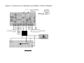
The input supply voltage is connected to the points labeled "PWR".
Lights signals and other devices controlled can be connected to the
contacts labeled "LIGHT SIGNAL". The direct current train
transformer used for analog systems is connected to the terminal
block labeled "TRACK IN", while power is supplied to the
separated section isolated on both tracks from the points labeled
"TRACK OUT".
The external sensor used to decelerate the locomotive from the
given point connects to the points "POS". In case of manual
operation, when power is supplied to the input labeled "GO", the
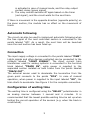
train starts to accelerate. See Figure 1 for the complete connection.
Configuration of waiting time
The waiting time is configured using the "DELAY" potentiometer in
an analog manner between 1 second and 4 minutes. It is
recommended that the lowest possible waiting time be set up when
testing the correct operation of the sensors (e.g. when the track is
constructed).
3
Should you choose the manual mode for releasing the trains, turn
the potentiometer to the lowest value (see Figure 1). In this case,
the train is only launched manually, and no waiting time is set up.
Configuration of Deceleration Rate
Use the potentiometer labeled "DISTANCE" to configure the
degree of train deceleration. Configure the deceleration rate so that
all locomotives are able to stop within deceleration distance of the
activation sensor ("POS").
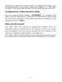
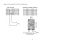
POS and GO Inputs
The "POS" and "GO" inputs are galvanically isolated. They are
activated using AC (alternating) or DC (direct) current. This power
may be supplied from any source, be that the rail contacts or the
output of a reflection object sensor. (see Figure 2)
The "POS" sensor must be placed a few centimeters from the end of
the section. The locomotive will decelerate starting from this point.
4
Guarantee and Legal Statement
Each parameter of the device has been submitted to extensive
testing prior to marketing. The manufacturer undertakes one year
guarantee for the product. Defects occurred during this period will
be repaired by the manufacturer free of charge against the
presentation of the invoice.
The validity of the guarantee will cease in case of improper usage
and/or treatment.
Attention! By virtue of the European EMC directives the product can
be used solely with devices provided with CE marking.
The mentioned standards and brand names are the trademarks of the
firms concerned.
TrainModules – BioDigit Ltd
Kerepesi street 92.
H-1144, Budapest
Made in Hungary.
Tel.: +36 1 46 707 64
http://www.trainmodules.hu/
5
Figure 1 Connection of Braking and Station Control Module
LIGHT
SIGNAL
Figure 2. Connection of the Control Input
1