1
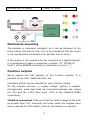
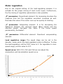
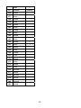
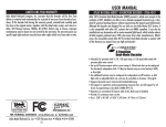
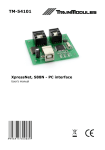
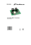
TM-56232 Load-regulated locomotive decoder User's manual © 2011 BioDigit Ltd. All rights reserved. It is forbidden to reproduce and/or publish the contents of the present document in any form including electronic and mechanical design without the written permission of BioDigit Ltd. Safety warning During the operation of the device the specified technical parameters shall always be met. At the installation the environment shall be fully taken into consideration. The device must not be exposed to moisture and direct sunshine. A soldering tool may be necessary for the installation and/or mounting of the devices, which requires special care. During the installation it shall be ensured that the bottom of the device should not contact with a conductive (e.g. metal) surface! Contents Safety warning ...................................................................... 1 Properties ............................................................................. 2 Technical parameters ............................................................. 2 Short description ................................................................... 2 Mounting of the decoder ......................................................... 2 Mechanical mounting .............................................................. 3 Function outputs .................................................................... 3 DCC speed formats ................................................................4 Digital and analog operating mode ........................................... 4 Decoder settings (programming) .............................................. 4 Decoder address settings ........................................................ 6 Motor regulation .................................................................... 7 Restoring the decoder base settings ......................................... 8 Decoder CV table ................................................................... 9 Function association table ..................................................... 11 Guarantee and legal statement .............................................. 13 1 Properties Developed for NMRA DCC systems Load-controlled motor driving Individual effect for each output Changeable motor PID regulation parameters DirectCV and POM programming mode Interchangeable function numbers Compact designs Mountable into TT and certain N models Technical parameters Supply voltage: 5-20V Idle mode current consumption: 20 mA Max. current consumption: 1000 mA Connector type: NEM652 Motor excitation frequency: 32KHz Address range: 1-9999 + Consist Address Dimensions: 16x10 mm Short description The most important advantage of the load-regulated decoder is the constant motor revolution number at low speed. The decoder contains switchable outputs, where to various external loads can be connected. Mounting of the decoder Important! Each capacitor on the motor poles and the engine frame must be removed! Contact assignment of the standard NEM652 connector (Name, pin number, wire color): + Motor (1, orange) Right side rail (8, red) Rear light / Back-up light (2, + supply, common (7, blue) yellow) Front light / Headlight (6, White) 2 Left side rail (4, black) - Motor (5, grey) Mechanical mounting The decoder is externally insulated, so it can be fastened to the frame easily and without risk. It is to be considered that the motor is not mechanically hindered by the decoder and its wires. If the engine is not prepared for the reception of a digital decoder, it is practicable to apply a preparatory module. (Pl. TM-56271) Point 1 of the NEM652 connector is marked by a circle ( ° ). Function outputs Never exceed the load capacity of the function outputs! It is possible to use LED, traditional bulb, etc. Individual effects can be selected for each function output. On the outputs common „+ supply voltage” system is applied. Consequently, each load shall be connected between the output (FL, RL) and the +16V (blue wire). (This is the standard NMRA connection). If bulb is connected: Take care that the rated voltage of the bulb be greater than 12V. Generally the bulbs inside the engines have been prepared for 16V system, thus no intervention is required. 3 If LED is connected: Engines originally provided contain the serial current limiting resistors as well. LEDs are applied, a serial current limiting resistor is to each of them. Generally a 4,7 KOhm 0,6W resistor is most LEDs. with LEDs If separate be used for suitable for DCC speed formats The decoder automatically detects the speed formats. Supported speed formats: 14/27/28/128. The correct operation of the speed modes is guaranteed and tested in the following systems: - ESU ECoS ® Roco ® Lokmaus 2, Lokmaus 3, Multimaus Uhlenbrock ® Intellibox Lenz ® Digital Plus V2 ZIMO ® MX1 In systems Lenz ® Digital Plus V3.0 only the 28/128 speed formats are available. Digital and analog operating mode Change-over occurs automatically. In digital mode the motor is regulated, in analog mode the decoder transfers maximal supply voltage for the motor. Thus in analog mode the decoder intentionally ignores the acceleration and deceleration parameters. The speed mode 128 is proposed to achieve smooth running! In analog mode the decoder operates over 5V! Decoder settings (programming) The so-called CVs (Configuration Variable) can be used for setting. The decoder keeps these settings even after being switched off. 4 The decoder CV programming mode can be accessed by various methods depending on the digital centre. The user's manual of the digital centre contains detailed information. NMRA standards The decoder complies with the specification of the NMRA (National Model Railroad Association) standard in every respect. Thus the setting addresses meet the standard. Programming process The procedure can be explained by a simple address setting example. The original address 3 will be changed to 79 in our example (less than 127): 1. Direct CV mode We need a separate programming rail with only the engine to be programmed! In our digital centre select the Direct CV setting mode. The system prompts for the setting address. Enter the CV address of the „primary address”: 1. Give the new CV value entering „79” and start programming. A short motor moving and a flashing light indicate to the digital centre that the decoder has performed setting. Thereafter the decoder can be controlled through the new address „79”. 2. POM mode In this case no separate programming rail is required, but we have to be aware of the current address of the decoder. In this mode first the engine address then the CV address and at last the new value shall be given. The user's manual of the digital centre contains detailed information on programming. 5 Decoder address settings Using short addresses: According to the DCC standard the decoders can have an address range of 1 to 127 in case of short addressing. For short address programming two register values shall be set: CV1: Short address CV29 – bit 5: Selection of short and long address. Enter address 79 in our example. CV1 = 79 CV29 – bit 5 = 0 Using long addresses: This address range shall be used between 128 and 9999. Long addresses are often used when the track number of the engine is in question. Three register values shall be modified: CV17: Upper address byte CV18: Lower address byte CV29 – bit 5 = Selection of short and long address. In our example we give address 5009 to the engine. We should use the long address setting if the digital centre is provided with this option. If the digital centre fails to modify the CV29 value, the bit 5 shall be set to 1 by bit modification or value rewriting. Calculation of the CV17 and CV18 values: 5009 / 256 = 19 with reminder 145 CV17 = 192 + 19 CV18 = 145 Our web page helps you to calculate the addresses and settings: http://www.trainmodules.hu/tips_decoder_address.html 6 Motor regulation Due to the original setting of the load-regulating decoder it is suitable for the proper driving of most motor types. Furthermore, the fine-tuning of regulation parameters is also possible. „P” parameter: Proportional element. Its increasing shortens the response time but the regulation overshoot increases as well. Decrease this value if the motor runs up too quickly at starting. „I” parameter: Integrating element. It is for decreasing the difference between the required speed (Base signal) and the effective speed. Decrease this value if the motor speed permanently „fluctuates”. „D” parameter: Differential element. Overshoot compensating element. Load regulation range: The speed stage can be set in the decoder, under which the load-regulated mode is effective. To stop the load-regulation, set the CV57 value to 0. For regulation in max. speed range, set the value to 127. Speed curve: With CV2, CV5 and CV6 we can adjust the acceleration and decceleration speed curve. 7 Base function F0: Light (Front and Rear) – Normal engine light, dependent on the running direction. F3: Marshalling run (50% speed usual for decoders) F4: Ignoring acceleration and deceleration parameters F5: Beam deflectors F0 Front, F0 Rear, functions can be programmed for separate light effects. See: CV113 - CV116 Restoring the decoder base settings Each setting of the decoder reverts to the original value if value „8” is written in the CV8 register. 8 Decoder CV table Name CV Value range Primary address Min. speed Acceleration Deceleration Max. speed Medium speed Version number Reset / Manufacturer ID Analog functions (F1-F8) 1 2 3 4 5 6 7 8 1-127 0-75 0-63 0-63 0-63 0-63 Read only Writing value 8 everything returns to original basic setting 0/1 = F1 0 0/2 = F2 0/4 = F3 0/8 = F4 0/16 = F5 0/32 = F6 0/64 = F7 0/128 = F8 Extended address Consist Address Consist Function Setting reg. I. PID regulating „P” (proportional element) PID regulating „I” (integrating element) PID regulating „D” (deriving element) 13 17+ 18 19 21 29 Original setting 3 0 50 50 63 22 Example: F1+F2+F4 = 1 + 2 + 8 = 11 192-9999 1-127 – Normal direction 129-255 = Reverse direction 0/1 = F1 0/2 = F2 0/4 = F3 0/8 = F4 0/16 = F5 0/32 = F6 0/64 = F7 0/128 = F8 Example: F1+F2+F4 = 1 + 2 + 8 = 11 0/1 = Normal/Reverse direction 0/2 = 28 and 128 speed stage. 0/4 = Digital only / Analog-Digital mode 0/8 = BiDi communication OFF/ON 0/32 = Primary address range / Extended address (17-18 reg. setting!) 192 0 0 4 54 Example: Engine speed + Analog-Digital mode = 2 +4=6 0-80 25 55 0-80 5 56 0-80 48 9 Name CV Value range PID regulating range 57 0-127 Light effect frequency Front light 112 113 Rear light 114 Changing point related format 128 4-64 Normal light intensity Blinking (Phase 1) Blinking (Phase 2) Flashing Double flashing Fire effect Smoke generator Increase intensity „Marslight” „Gyrolight” „Rule 17” for front light „Rule 17” for rear light Pulse output Original setting 127 to the speed Vol Vol+16 Vol+32 Vol+48 Vol+64 Vol+80 Vol+96 Vol+112 Vol+128 Vol+144 Vol+160 Vol+176 Vol+192 Vol = Max. light intensity Range: 0-15 Normal light intensity Vol Blinking (Phase 1) Vol+16 Blinking (Phase 2) Vol+32 Flashing Vol+48 Double flashing Vol+64 Fire effect Vol+80 Smoke generator Vol+96 Increase intensity Vol+112 „Marslight” Vol+128 „Gyrolight” Vol+144 „Rule 17” for front light Vol+160 „Rule 17” for rear light Vol+176 Pulse output Vol+192 Vol = Max. light intensity Range: 0-15 10 33 127 127 Function association table CV Value 1 2 Function FHL RHL 129 F0 fwd 130 F0 rev 4 8 16 32 64 128 Shunt AccDec 1 2 131 F1 fwd 132 F1 rev 133 F2 fwd 134 F2 rev 135 F3 fwd 64 136 F3 rev 64 137 F4 fwd 128 138 F4 rev 128 139 F5 fwd 140 F5 rev 141 F6 fwd 142 F6 rev 143 F7 fwd 144 F7 rev 145 F8 fwd 146 F8 rev 147 F9 fwd 148 F9 rev 149 F10 fwd 150 F10 rev 151 F11 fwd 152 F11 rev 153 F12 fwd 154 F12 rev 11 Value 1 CV Function 156 F0 fwd 157 F0 rev 158 F1 fwd 159 F1 rev 160 F2 fwd 161 F2 rev 162 F3 fwd 163 F3 rev 164 F4 fwd 165 F4 rev 166 F5 fwd 1 167 F5 rev 1 168 F6 fwd 169 F6 rev 170 F7 fwd 171 F7 rev 172 F8 fwd 173 F8 rev 174 F9 fwd 175 F9 rev 176 F10 fwd 177 F10 rev 178 F11 fwd 179 F11 rev 180 F12 fwd 181 F12 rev Dimmer 12 Guarantee and legal statement Each parameter of the device was submitted to comprehensive testing prior to marketing. The manufacturer undertakes one year guarantee for the product. Defects occurred during this period will be repaired by the manufacturer free of charge against the presentation of the invoice. The validity of the guarantee will cease in case of improper usage and/or treatment. Attention! By virtue of the European EMC directive the product can be used solely with devices provided with CE marking. The mentioned standards and branch names are the trademarks of the firms concerned. TrainModules – BioDigit Ltd Kerepesi street 92. H-1144, Budapest Made in Hungary. Tel.:+36 1 46-707-64 http://www.trainmodules.hu/ 13