1
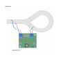
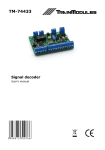
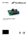
TM-73856 Loop and delta module User's manual © 2011 BioDigit Ltd. All rights reserved. It is forbidden to reproduce and/or publish the contents of the present document in any form including electronic and mechanical design without the written permission of BioDigit Ltd. Safety warning During the operation of the device the specified technical parameters shall always be met. At the installation the environment shall be fully taken into consideration. The device must not be exposed to moisture and direct sunshine. A soldering tool may be necessary for the installation and/or mounting of the devices, which requires special care. During the installation it shall be ensured that the bottom of the device should not contact with a conductive (e.g. metal) surface! Contents Safety warning ...................................................................... 1 Properties ............................................................................. 2 Technical parameters ............................................................. 2 Short description ................................................................... 2 Wiring .................................................................................. 2 Adjustment ...........................................................................2 Guarantee and legal statement ................................................ 3 1 Properties Developed for DCC systems Automatic polarity change Requires no separate supply Adjustable sensitivity Technical parameters Supply voltage: 7-24V Idle mode current consumption: 20 mA Max. current consumption: 40 mA Dimensions: 42x36 mm Short description The connection of returning loop and delta tracks causes short circuit. The module automatically detects the short circuit produced during driving in and leaving the loop and automatically changes the polarity on the isolated loop section, thus avoiding permanent short circuit status. Change occurs so quickly that the engine smoothly passes along the section. Wiring The module shall be connected between the arriving and the isolated loop section as it is shown in Figure 1. The isolation of the loop section is ensured by the cutting of both rails at both sides. Adjustment After wiring the module can be put into service. Turn the potentiometer "Sensitivity" to a position where the relay on the module continuously switches on and off in an audible mode. Then turn the potentiometer back until continuous switching on and off permanently ceases. 2 Guarantee and legal statement Each parameter of the device was submitted to comprehensive testing prior to marketing. The manufacturer undertakes one year guarantee for the product. Defects occurred during this period will be repaired by the manufacturer free of charge against the presentation of the invoice. The validity of the guarantee will cease in case of improper usage and/or treatment. Attention! By virtue of the European EMC directive the product can be used solely with devices provided with CE marking. The mentioned standards and branch names are the trademarks of the firms concerned. 3 Figure 1