1
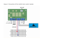
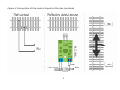
TM-78261 Shuttle Train Controller User's Manual © 2012 BioDigit Ltd. All rights reserved. It is forbidden to reproduce and/or publish the contents of the present document in any form including electronic and mechanical design without the written permission of BioDigit Ltd. Safety Warnings During the operation of the device, the specified technical parameters shall always be met. At the installation, the environment shall be fully taken into consideration. The device must not be exposed to moisture and direct sunshine. A soldering tool may be necessary for the installation and/or mounting of the devices, which requires special care. During the installation it shall be ensured that the bottom of the device should not contact with a conductive (e.g. metal) surface! Contents Safety Warnings ....................................................................1 Features and Properties .......................................................... 2 Technical Parameters ............................................................. 2 Short description ................................................................... 2 Connection............................................................................ 2 Operation ............................................................................. 3 Configuration of waiting time ................................................... 3 IN1 and IN2 inputs................................................................. 3 Guarantee and Legal Statement ............................................... 0 1 Features and Properties Developed for analog systems Delay can be adjusted between 1 second and 2 minutes Controlled by external sensors Light signal control outputs Low stand-by current consumption Technical Parameters Input supply voltage: 7-24V AC/DC Control input supply voltage: 4-24V AC/DC Stand-by current consumption: 20 mA Maximum current consumption: 65 mA Size: 74x47 mm Short description The circuit can be used to set up a shuttle train moving between two terminal points. The benefit of the circuit is that the locomotive stop positions can be changed arbitrarily by placing the sensors. The inputs are galvanically isolated. This means that it can be used with both the rail contact and the reflection object sensor (TM73379). The potentiometer located on the module can be used for the analog setting of the time spent at the given end stations between 1 second and 2 minutes. Connection The input supply voltage is connected to the points labeled "PWR". Light signals and other devices controlled depending on the direction can be connected to the SPDT switch contacts labeled "CTRL". The direct current train transformer used for analog systems is connected to the terminal block labeled "TRACK IN", while power is supplied to the shuttle train section isolated on both tracks from the points labeled "TRACK OUT". 2 External sensors used to stop the locomotive at the given point are connected to the points "IN1" and "IN2". See Figure 1 for the completed connection. Operation The circuit activates the output when switched on, and launches the locomotive on the track in the primary direction (positive polarity). Once the locomotive has reached the sensor connected to the points IN1 (see Figure 2), the output is immediately switched off. When the configured waiting time elapses, the locomotive on the track is launched in the opposite direction (with negative polarity). Once the locomotive has reached the sensor connected to point IN2, the locomotive once again comes to a halt. When the waiting time elapses, the locomotive is once again launched with positive polarity. The "CTRL" contacts are also activated in line with the current direction set up. These may also be used for example to control light signals and switches. Configuration of waiting time The waiting time is configured using the "DELAY" potentiometer in an analog manner between 1 second and 2 minutes. It is recommended that the lowest possible waiting time be set up when testing the correct operation of the sensors (e.g. when the track is constructed). IN1 and IN2 inputs The IN1 and IN2 inputs are galvanically isolated. They are activated using AC (alternating) or DC (direct) current. This power may be supplied from any source, be that the rail contacts or the output of a reflection object sensor. (See Figure 2) The two inputs must be activated when the terminals are reached. The sensors must be placed accordingly. 3 Guarantee and Legal Statement Each parameter of the device has been submitted to extensive testing prior to marketing. The manufacturer undertakes one year guarantee for the product. Defects occurred during this period will be repaired by the manufacturer free of charge against the presentation of the invoice. The validity of the guarantee will cease in case of improper usage and/or treatment. Attention! By virtue of the European EMC directives the product can be used solely with devices provided with CE marking. The mentioned standards and brand names are the trademarks of the firms concerned. TrainModules – BioDigit Ltd Kerepesi street 92. H-1144, Budapest Made in Hungary. Tel.: +36 1 46 707 64 http://www.trainmodules.hu/ 4 Figure 1 Connection of the shuttle train control module Figure 2 Connection of the control inputs at the two terminals 1