1
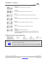
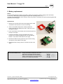
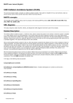
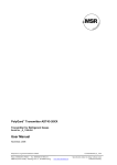
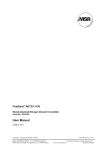
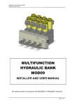
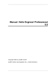
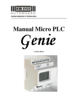
Analog/ Digital Datalogger T-Logg 120
Data Logger for Standard Signals
T-Logg 120 K and T-Logg 120 W
As of version 1.0
User Manual
December, 2010
PolyGard is a registered trademark of MSR
Phone 0049(0)8531/9004-0 Fax: 0049(0)8531/9004-54
MSR-Electronic GmbH, Würdinger Str. 27, D 94060 Pocking
GAT-Logg120_E_1210
www.msr-electronic.de
Specification subject to change without notice
Printed in Germany
User Manual - T-Logg 120
Page
2
1
General ................................................................................................................................................ 3
2
Required Accessory........................................................................................................................... 3
3
Safety Instructions ............................................................................................................................. 3
4
Connection.......................................................................................................................................... 3
4.1
4.2
4.3
Interface Connection .................................................................................................................. 3
T-Logg 120 W - ...: Assignment of the Angle-type Plug............................................................. 4
T-Logg 120 K - ...: Assignment of the Connection Cable........................................................... 5
5
Advice Regarding State of Logger upon Delivery .......................................................................... 5
6
Configuration of the Display Range ................................................................................................. 5
7
Operating Mode Display .................................................................................................................... 5
8
Battery service life and recording time............................................................................................ 6
9
Battery replacement........................................................................................................................... 7
10
Specifications .................................................................................................................................. 8
11
Disposal instructions ...................................................................................................................... 8
12
Notes and General Information ...................................................................................................... 9
12.1
12.2
12.3
12.4
Intended Product Application.................................................................................................. 9
Installers’ Responsibilities ...................................................................................................... 9
Maintenance ........................................................................................................................... 9
Limited Warranty..................................................................................................................... 9
PolyGard is a registered trademark of MSR
Phone 0049(0)8531/9004-0 Fax: 0049(0)8531/9004-54
MSR-Electronic GmbH, Würdinger Str. 27, D 94060 Pocking
GAT-Logg120_E_1210
www.msr-electronic.de
Specification subject to change without notice
Printed in Germany
User Manual - T-Logg 120
Page
3
1 General
The logger T-Logg 120 ... is designed as a cost-efficient solution for monitoring standard signals. It enables an
individual programming of the recording time. The last 16,000 measuring values can be stored in the memory.
In addition, the LCD-display indicates both the temperature measured at the moment and the operating status
of the logger.
2 Required Accessory
The USB interface of your PC is used to program, start and read out the T-Logg.
For this following accessory is required:
• Interface converter USB 100 or USB 100 SL for direct connection to the USB port of the PC, cable length
approx. 1m.
• MINISOFT software (version 7.18 or later / free of charge) to start the logger and read out the logger data.
Notice:
It’s also possible to use the T-Logg with the comprehensive software GSOFT 40K
(version 7.18 or later).
3 Safety Instructions
This device has been designed and tested in accordance with the safety regulations for electronic devices.
However, its trouble-free operation and reliability cannot be guaranteed unless the standard safety measures
and special safety advises given in this manual will be adhered to when using the device.
1. Trouble-free operation and reliability of the device can only be guaranteed if the device is not subjected to
any other climatic conditions than those stated under ‘Specification’
To protect the battery the max. permissible storage and transport temperature of the device is +85°C.
2. General instructions and safety regulations for electric, light and heavy current plants, including domestic
safety regulations (e.g. VDE), have to be observed.
3. If device is to be connected to other devices (e.g. via PC) the circuitry has to be designed most carefully.
Internal connection in third party devices (e.g. connection GND and earth) may result in not-permissible
voltages impairing or destroying the device or another device connected.
4. If there is a risk whatsoever involved in running it, the device has to be switched off immediately and to be
marked accordingly to avoid re-starting.
Operator safety may be a risk if:
- there is visible damage to the device.
- the device is not working as specified.
- the device has been stored under unsuitable conditions for a longer time.
In case of doubt, please return device to manufacturer for repair or maintenance.
5.
Warning:
Do not use this product as safety or emergency stop devices, or in any other application where failure of the
product could result in personal injury or material damage.
Failure to comply with these instructions could result in death or serious injury and material damage!
4 Connection
4.1 Interface Connection
Assignment of the input jack
(front view to the pins):
interface [–]
not connected
interface [+]
PolyGard is a registered trademark of MSR
Phone 0049(0)8531/9004-0 Fax: 0049(0)8531/9004-54
MSR-Electronic GmbH, Würdinger Str. 27, D 94060 Pocking
GAT-Logg120-E-1210
www.msr-electronic.de
Specification subject to change without notice
Printed in Germany
User Manual - T-Logg 120
Page
4
4.2 T-Logg 120 W - ...: Assignment of the Angle-type Plug
Table of connections angle-type socket and jack
Pin No.
Inputs
Wire Colour
0 ... X Volt
0 ... 20 mA
4 ... 20 mA
1
blue
feeded through, signal +
feeded through
feeded through
2
red
feeded through , signal -
feeded through
T-Logg
3
black
feeded through
T-Logg
feeded through
4
yellow
feeded through
feeded through
feeded through
Input Signal: 0 ... X Volt
Input Signal: 0 ... 20 mA
Input Signal: 4 ... 20 mA
In the angle-type plug the 4
male contacts are directly
connected 1:1 with the socket.
The logger connection is on
contact 1 (signal+) and
contact 2 (signal-).
In the angle-type plug the male
contacts 1, 2 and 4 are directly
connected 1:1 with the socket.
The T-Logg (Rs = ~70 Ohm) is
located between the male
contact 3 (-) and the jack 3 (+).
In the angle-type plug the male
contacts 1, 3 and 4 are directly
connected 1:1 with the socket.
The T-Logg (Rs = ~70 Ohm) is
located between the male
contact 2 (-) and the jack 2 (+).
If your transmitter
assignments for the 'signal+'
and 'signal-' are different,
please do not forget to adjust
male contacts of your angletype plug accordingly:
To do so open the angle-type
plug and remove the red and
the blue wires entering the
housing from the coupling of
the angle-type plug.
Connect wires with the
respective contacts,
representing signal + (blue
wire) and signal - (red wire) at
your transmitter.
pin contact
pin contact
1
2
3
4
1
2
3
4
_
_
Rs
Rs
+
1
2
3
4
+
1
2
3
4
jack
jack
If the 'signal'-line in your
transmitter is not assigned to
contact 3, please do not forget to
adjust the logger-angle-type plug
and the external angle-type plug
accordingly:
If the 'signal/GND'-line in your
transmitter is not assigned to
contact 2, please do not forget to
adjust the logger-angle-type plug
and the external angle-type plug
accordingly:
To do so open the logger-angletype plug and exchange the
black wire of contact 3 against
the wire of the contact
representing the 'signal' in your
transmitter.
Then exchange and/or rewire the
two contacts in the angle-type
plug of your connecting cable.
To do so open the logger-angletype plug and exchange the red
wire of contact 2 against the wire
of the contact representing the
'signal/GND' in your transmitter.
Then exchange and/or rewire the
two contacts in the angle-type
plug of your connecting cable.
How to change the assignment of the angle-type plug:
•
Dismantle the plug by pulling the adapter inset out of the case, using a screw-driver at the lateral
groove.
•
Change the assignment according to the notes at the respective input signal.
•
Latch coupling insert in cover. You have a choice between 4 different orientations - each of them
spaced 90°.
•
Please make sure to adjust the connecting cable, if the assignment of the angle-type plug has
been changed for the types 4-20mA and 0-20mA.
•
Put on angle-type plug and connect plugs using the long screw delivered. (Do not forget seals).
PolyGard is a registered trademark of MSR
Phone 0049(0)8531/9004-0 Fax: 0049(0)8531/9004-54
MSR-Electronic GmbH, Würdinger Str. 27, D 94060 Pocking
GAT-Logg120-E-1210
www.msr-electronic.de
Specification subject to change without notice
Printed in Germany
User Manual - T-Logg 120
Page
5
4.3 T-Logg 120 K - ...: Assignment of the Connection Cable
The connection cable has following assignment:
Wire colour
Meaning
red
signal +
white
signal -
5 Advice Regarding State of Logger upon Delivery
Upon its delivery the logger is in a kind of 'sleeping state':
The display does not show anything, the power consumption is at its minimum.
The T-Logg ‘wakes up’ as soon as a communication link with a software has been established. After that the
message “Stop” appears at display. The logger is ready for operation now.
6 Configuration of the Display Range
The display range, position of decimal point and the display unit can be set by the software MINISOFT
(or GSOFT 40K) in the register “Settings”.
Furthermore, it can be used to read out sensor information and to program the alarm points of the logger.
7 Operating Mode Display
The T-Logg is equipped with a 10 mm LCD display.
The main purpose of the LCD display is to indicate the measured value. Depending on the operating mode of
the logger, other messages will be displayed as well.
STOP:
The T-Logg is ‘stopped’. No data are recorded. The logger memory is empty.
The logger is reset and can be restarted.
HALT:
The T-Logg has been ‘halted’. The stored data can be read.
The logger memory is not empty.
DISPLAY OF MEASURED VALUE:
The small arrow is flashing The logger is active.
Measurements are carried out at certain intervals. The measured value will be
stored.
START DELAY:
The logger is active, but no data are recorded.
As soon as the start delay time has expired, the logger will start recording in
accordance with the starting conditions programmed before.
START ALARM:
The logger is active, but no data are recorded. Recording will start as soon as the
measured value is within the min. and max. alarm limits.
BATTERY:
• Changing display BAT / Value:
The battery of the T-Logg is getting discharged soon.
Replace the battery briefly. Even so data logging is still active.
• Constant display BAT:
The Logger battery is empty now and data logging has been stopped.
Replace the battery immediately.
PolyGard is a registered trademark of MSR
Phone 0049(0)8531/9004-0 Fax: 0049(0)8531/9004-54
MSR-Electronic GmbH, Würdinger Str. 27, D 94060 Pocking
GAT-Logg120-E-1210
www.msr-electronic.de
Specification subject to change without notice
Printed in Germany
User Manual - T-Logg 120
Page
6
ALARM LOW:
The measured value is below the min. alarm limit.
ALARM HIGH:
The measured value has exceeded the max. alarm limit.
ERROR 1:
The input signal has exceeded the measuring range of the logger.
ERROR 2:
The input signal has been fallen below the measuring range of the logger.
ERROR 3:
The max. display range (9999) of the logger is exceeded.
ERROR 4:
The min. display range (-1999) of the logger is under-run.
ERROR 7:
The T-Logg has detected a system fault.
• Remedy:
Remove battery and wait about 30 minutes. Then insert the battery again.
• If the error message displayed furthermore, please send the logger to the
manufacturer to repair.
8 Battery service life and recording time
Measuring cycle:
Recording time:
Battery service life:
Please note!
2 sec.
8.9 hours
—
10 sec.
44 hours
Approx. 1 year
15 min.
166 days
Approx. 3 years
5 hours
Approx. 9 years
—
Short measuring cycles as well as frequently measuring data transfer result in a
reduction of the battery service life!
Even if the T-Logg is connected, power consumption is increased. So it’s important
to connect the logger with the USB interface of the PC only as long as necessary!
PolyGard is a registered trademark of MSR
Phone 0049(0)8531/9004-0 Fax: 0049(0)8531/9004-54
MSR-Electronic GmbH, Würdinger Str. 27, D 94060 Pocking
GAT-Logg120-E-1210
www.msr-electronic.de
Specification subject to change without notice
Printed in Germany
User Manual - T-Logg 120
Page
7
9 Battery replacement
Notice:
As soon as BAT appears at display, the battery needs to be replaced. If battery voltage power decreases
continuously, data logging will be stopped (compare with operating status ‘HALT’).
Available stored data remains in the memory and do not get lost. It’s possible to read the measuring data after
replacement of the battery!
Replacement:
1. Remove the 4 screws at the front of the logger with a small
screwdriver and remove the cover from housing.
2. Take out the PCB and deposit it carefully beside the
housing with the LCD display face down. Take care not to
damage the gasket.
3. Push out the button cell carefully from socket (see picture at
the top on the right).
4. Insert the new button cell (type CR 2032) with correct
polarity in the socket (the positive pole is on the retaining
bracket – see picture at the bottom on the right).
5. Reinsert the PCB correctly (LCD face up) into the housing
(see picture in the middle on the right).
+
6. Reassemble the housing. Use the 4 screws to fix the cover
again.
Environmental Reference!
Empty and defective batteries must not be
disposed in the regular domestic waste.
Return the used batteries to an authorised
battery collecting point or send the batteries
directly to us (sufficiently stamped).
PolyGard is a registered trademark of MSR
Phone 0049(0)8531/9004-0 Fax: 0049(0)8531/9004-54
MSR-Electronic GmbH, Würdinger Str. 27, D 94060 Pocking
GAT-Logg120-E-1210
www.msr-electronic.de
Specification subject to change without notice
Printed in Germany
User Manual - T-Logg 120
Page
8
10 Specifications
Input signal
Display range
Scaling
Decimal point
Accuracy
Display
Recording Interval
Measuring value memory
Memory type
Recording time
Alarm function
Nominal temperature
Working temperature
Storage temperature
Battery
Battery service life
Interface
Data communication
Electric connection
T-Logg 120 K - ...
T-Logg 120 W - ..
Dimensions / housing
EMC
refer to device type, or in according to type plate
T-Logg 120 .. - 001: 0 – 1 Volt
input resistance = ~ 100 kOhm
T-Logg 120 .. - 002: 0 – 2 Volt
input resistance = ~ 200 kOhm
T-Logg 120 .. - 010: 0 – 10 Volt input resistance = ~ 500 kOhm
T-Logg 120 .. - 020: 0 – 20 mA shunt resistance = ~ 70 Ohm
T-Logg 120 .. - 420: 4 – 20 mA shunt resistance = ~ 70 Ohm
-1999 ... 9999 digit
freely programmable via software
setable to any position
± 0.5% FS (at nominal temperature)
LCD display, 10 mm high, 4-digit
2s to 5h
16,000 values
FILLING MEMORY:
>> Once the memory is filled with data, the recording will automatically be
halted.
RING MEMORY:
>> The old data will be overwritten in case of memory overflow.
approx. 9 hours up to 9 years, depending on measuring cycle
the measured values are monitored at alarm limits.
Alarm limit and alarm delay (0 ... 500 min.) adjustable via interface
+25 °C
-25 … +60 C
-30 … +85 C
CR 2032, exchangeable
approx. 3 years (if interval is 15 min.), depending on measuring cycle and
operating temperature
serial interface, 3-pin miniature plug
Please note: the input is not isolated from the interface!
via interface converter
approx. 0.5 m silicone connection cable
angle-type plug in accordance to DIN43650
48.5 x 48.5 x 35.5 mm (H x W x D), plug an fixation flap not included.
Housing made of shock resistant plastic, transparent front made of
polycarbonate, splash water-proof IP65
The T-Logg 120 ... have been manufactured in accordance with the
regulations concerning EMC (2004/108/EG).
The device meets EN 61326-1:2008
Additional error: <1%
11 Disposal instructions
The device must not be disposed in the regular domestic waste. Send the device directly to us (sufficiently
stamped), if it should be disposed. We will dispose the device appropriate and environmentally sound.
PolyGard is a registered trademark of MSR
Phone 0049(0)8531/9004-0 Fax: 0049(0)8531/9004-54
MSR-Electronic GmbH, Würdinger Str. 27, D 94060 Pocking
GAT-Logg120-E-1210
www.msr-electronic.de
Specification subject to change without notice
Printed in Germany
User Manual - T-Logg 120
Page
9
12 Notes and General Information
It is important to read this user manual thoroughly and clearly in order to understand the information and
instructions. The MSR-Electronic devices must be used within product specification capabilities. The
appropriate operating and maintenance instructions and recommendations must be followed.
Due to on-going product development, MSR reserves the right to change specifications without notice. The
information contained herein is based upon data considered to be accurate. However, no guarantee is
expressed or implied regarding the accuracy of this data.
12.1 Intended Product Application
The MSR-Electronic devices are designed and manufactured for control applications and air quality compliance
in commercial buildings and manufacturing plants (i.e. detection and automatic exhaust fan control for
automotive maintenance facilities, enclosed parking garages, engine repair shops, warehouses with forklifts,
fire stations, tunnels, etc.).
12.2 Installers’ Responsibilities
It is the installer’s responsibility to ensure that all MSR-Electronic devices are installed in compliance with all
national and local codes and OSHA requirements. Installation should be implemented only by technicians
familiar with proper installation techniques and with codes, standards and proper safety procedures for control
installations and the latest edition of the National Electrical Code (ANSI/NFPA70). It is also essential to follow
strictly all instructions as provided in the user manual.
12.3 Maintenance
It is recommended to check the MSR-Electronic device regularly. Due to regular maintenance any performance
deviations may easily be corrected. Re-calibration and part replacement in the field may be implemented by a
qualified technician and with the appropriate tools. Alternatively, the device may be returned for service to
MSR-Electronic-GmbH.
12.4 Limited Warranty
MSR-Electronic-GmbH warrants the MSR-Electronic devices for a period of one (1) year from the date of
shipment against defects in material or workmanship. Should any evidence of defects in material or
workmanship occur during the warranty period, MSR-Electronic-GmbH will repair or replace the product at their
own discretion, without charge.
This warranty does not apply to units that have been altered, had attempted repair, or been subject to abuse,
accidental or otherwise. The warranty also does not apply to units in which the sensor element has been
overexposed or gas poisoned. The above warranty is in lieu of all other express warranties, obligations or
liabilities.
This warranty applies only to the MSR-Electronic devices. MSR-Electronic-GmbH shall not be liable for any
incidental or consequential damages arising out of or related to the use of the MSR-Electronic® transmitters.
PolyGard is a registered trademark of MSR
Phone 0049(0)8531/9004-0 Fax: 0049(0)8531/9004-54
MSR-Electronic GmbH, Würdinger Str. 27, D 94060 Pocking
GAT-Logg120-E-1210
www.msr-electronic.de
Specification subject to change without notice
Printed in Germany