1
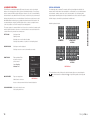
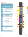
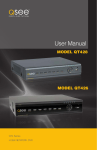
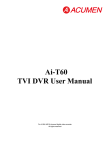
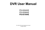
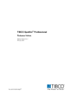
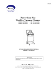
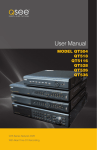
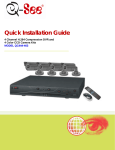
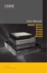
User Manual
MODEL QC444
H.264 NETWORK DVR
Variable CIF and D1 Recording Options
1
Meijer.com
About this Manual
Thank You for Choosing a Q-See Product!
All of our products are backed by a conditional service warranty covering all hardware for 12
THANK YOU FOR PURCHASING THIS Q-SEE PRODUCT.
months from the date of purchase. Additionally, our products also come with a free exchange
EVERY EFFORT HAS BEEN MADE TO MAKE THIS DVR SIMPLE TO ASSEMBLE AND USE. HOWEVER, IF
policy
that covers
all manufacturing
defects
for one
from theOR
date
of purchase.
YOU SHOULD
RUN INTO
ANY DIFFICULTIES
DURING
ITSmonth
INSTALLATION
OPERATION,
WE ARE HERE
FOR
YOU. upgrading service is provided for the software and is available at www.Q-See.com.
Permanent
Be certain to make the most of your warranty by completing the registration form online. In
addition to warranty and technical support benefits, you’ll receive notifications of product
updates along with free downloadable firmware updates for your DVR. Register today at
www.Q-See.com!
This manual is written for the QC444 DVR and was accurate at the time it was completed.
However, because of our ongoing effort to constantly improve our products, and the different
capabilities of the two models additional features and functions may have been added since
that time and on-screen displays may change. We encourage you to visit our website at
www.Q-see.com to check for the latest firmware updates and product announcements.
This manual covers the setup and local operation of the DVR. Instructions for configuring the
DVR for remote access, along with instructions for monitoring the DVR using a computer or
mobile device, are contained within the Remote Monitoring Guide which is included on the
CD that accompanied your DVR and which can also be found on www.Q-See.com.
Throughout the manual we have highlighted warnings and other important information that will
assist you in operating your new system in a safe and trouble-free manner. Please take the
time to read and follow all instructions and pay attention to alerts as shown below:
Please see the back of this manual for exclusions.
IMPORTANT! Red boxes with this icon indicate warnings. To prevent
possible injury or damage to the product, read all warnings before use.
NOTE! Text in blue boxes with the Information icon offer additional guidance
and explanations about how to make the most out of your system.
© 2011 Q-See. Reproduction in whole or in part without written permission is prohibited. All
rights reserved. This manual and software and hardware described herein, in whole or in part,
may not be reproduced, translated, or reduced to any machine-readable form without prior
written approval.
Trademarks: All brand names and products are trademarks or registered trademarks of their
respective owners.
Q-See is a registered trademark of DPS, Inc.
Disclaimer: The information in this document is subject to change without notice. The
manufacturer makes no representations or warranties, either express or implied, of any kind
with respect to completeness of its contents.
Manufacturer shall not be liable for any damages whatsoever from misuse of this product.
2
Version 1.2 5/16/11
3
Meijer.com
4. MENUS
TABLE OF CONTENTS
1. INTRODUCTION
2. CONNECTIONS AND CONTROLS
10
2.1 Front Panel
10
2.2 Rear Panel
11
2.3 Mouse Control
Virtual Keyboard
12
13
2.4 Remote Control
14
3. BASIC OPERATION
4
7
16
3.1 Operation
16
3.2 Live View
16
3.3 Login, Logout and Main Menu
Login
Main Menu
Shortcut Menu
Logout
Auto Resume
17
17
18
18
19
19
3.4 Recording
Manual Recording
19
19
3.5 Search and Playback
Search
Playback
20
21
22
3.6 Schedule
25
3.7 Motion, Video Loss and Camera Masking Detection
Motion Detection
Video Loss Camera Masking
Event Response
26
26
27
27
27
3.8 Backup
29
31
4.1 Main Menu
32
4.2 Info Menu
HDD Information
BPS
Log
Version
Online Users
32
32
33
33
34
34
4.3 Setting Menu
Encode
Snapshot
Schedule
Network
Default
35
37
39
40
40
41
4.4 Advanced
HDD Manage
Abnormality
Record
Account
Auto Maintainenance TV Adjust
42
42
43
43
43
44
44
4.5 Backup
44
4.6 Shutdown
44
5. HARD DISK DRIVE
45
5.1 Installation/Removal
45
5.2 Calculating the Recording Capacity of a Hard disk Drive
47
APPENDIX
48
A.1 Troubleshooting
48
A.2 Minimum Computer Configuration
51
Q-SEE PRODUCT WARRANTY
Questions or Comments? Contact Us
52
53
5
Meijer.com
INTRODUCTION
CHAPTER 1
To prevent damage to your Q-See product or injury to yourself or to others, read and
understand the following safety precautions in their entirety before installing or using this
equipment. Keep these safety instructions where all those who use the product will read them.
WARNING! ELECTRIC SHOCK RISK!
nCheck the unit and any accessories included in the package immediately after opening. If
items are missing or damaged, repackage and return to the point of purchase.
n Use the proper power source. Only use the power adapter supplied with your system. Do
not use this product with a power source that applies more than the specified voltage (100240V AC).
nNever insert anything metallic into the DVR. Inserting anything into the DVR or its case can
be a source of dangerous electric shock.
nDo not operate in dusty areas. Avoid placing the DVR in places that are dusty.
nDo not expose this product to rain or use near water. If this product accidentally gets wet,
unplug it and contact an authorized dealer immediately.
nKeep product surfaces clean and dry. To clean the outside case of the DVR, gently wipe
using a lightly dampened cloth (only use water, do not use solvents).
nDo not operate this DVR without the cover securely in place. Do not attempt to do any
repairs to the DVR yourself. If there are unusual sounds or smells coming from the DVR,
unplug it immediately and contact Q-See technical support. Under no circumstances
should the cover be removed while the device is connected to a power source. You should
only remove the cover to install/replace the hard disk drive (See Chapter 5) or replace the
standard 3v lithium cell battery on the motherboard. These are the only user serviceable
parts. You may need to replace the battery if the internal clock resets itself after a power
outage
nHandle DVR box carefully. If you accidentally drop your DVR on any hard surface, it may
cause a malfunction. If the DVR doesn’t work properly due to physical damage, contact an
authorized dealer for repair or exchange.
nMake sure there is proper air circulation around the unit. This DVR system uses a hard drive
for video storage which generates heat during operation. Do not block air holes located on
the bottom, top, sides and back of the DVR as they are designed to keep the system cool
while running. Install or place this product in an area where there is ample air circulation.
nProvide proper ventilation. This DVR has a built-in fan that properly ventilates the system.
Do not cover or impede this fan.
6
7
Meijer.com
FEATURES AND SPECIFICATIONS
Included Mouse and Remote Control
This combo DVR integrates a DVR (Digital Video Recorder) and LCD screen together. It is
an excellent digital monitor with a sleek appearance and innovative capabilities which are
functional and reliable.
In addition to the front panel button controls, system can also be booted up and shut down
using the included remote control or mouse. Mouse operation function supports intelligent
operation by enabling copy and paste functions.
It uses an embedded Linux OS to maintain stable operation and a popular H.264 compression
algorithm to produce high quality low bit stream footage that is easy to manage and efficient
to transfer over the internet. It can use various functions such as record, playback, and
monitoring at the same time and produces audio and video synchronization. This product has
advanced technology and strong network data transmission functions.
This combo DVR utilizes a high quality LCD capable of producing rich and vivid images. It’s
convenient 19-inch screen enables maximized viewing capabilities. This is an ideal system that can
be used in an in-home environment and a variety of business environments that require enhanced
monitoring capabilities such as: super markets, convenience stores, transportation, etc.
This product offers the following features:
Smartphone Compatible
Storage Function
Encrypted file format to ensure data security and avoid vicious data modification.
Compression Format
Supports multiple-channel audio and video. Independent hardware decodes the audio and
video signal from each channel to maintain video and audio synchronization.
24/7 Scheduled Recording
Choose which days of the week and hours of the day you want to set your DVR to record or
not record.
Multiple Playback Options and Advanced Search Functions
Access live footage directly from your iPhone, or other Smartphone. Your DVR can also
be set to e-mail your hand held-device whenever specific activity occurs, such as motion
detection.
Supports real-time recording on each channel independently. Search through recorded files
while you are playing live footage, monitoring through a remote location using a supported
internet browsing application and backing up system files. A variety of playback modes
include: slow play, fast play, backward play and frame by frame play.
View Your Video Feed Online with No Service Fees
Network Monitoring
View your DVR’s live or recorded video footage on any Internet accessible computer with
Internet Explorer, Mozilla Firefox and Google Chrome (using IE plug-in).
Supports network remote real-time monitoring (available bandwidth permitting) and remote
record search.
Stay Notified with Customizable Email Alerts
Set your system up to notify you when an event has occurred at the location you are
monitoring. Notification alerts can easily be adjusted to your specifications.
Advanced Motion Detection Activated Recording
Alarm Activation Function
Several relay alarm outputs enable you to pair your system with an on-site alarm system.
Communication Ports
s Standard Ethernet port allows you to access the DVR from a network or the Internet.
Advanced motion detection settings ensure that false alarms are not triggered. The easy to
use motion detect set up screen allows you to mask out certain areas which experience heavy
movement in order to avoid false alarms and avoid unnecessary record triggering.
Multiple Backup Options
A built-in USB port gives you the option of backing up and transferring your video footage
using a flash drive or external USB hard drive. You can also connect to an external CD/
DVD writer to burn your file footage right onto a compact disc or DVD disc. Files can also be
accessed from your DVR system to a remote computer location by logging on remotely.
Connect to a TV or PC Monitor Easily
This system comes with VGA and BNC video out ports to allow you to connect to a TV or
computer monitor for viewing purposes. You can utilize both outputs simultaneously.
8
NOTE! Depending on your point of purchase, your DVR may have the hard
disk drive already installed. If your drive was packaged separately, or if you
wish to upgrade your installed drive up to a 2TB drive, please see Chapter 5
at the back of this manual which covers installing the drive.
9
Meijer.com
CONNECTIONS AND CONTROLS
CHAPTER 2
2.2 REAR PANEL
2.1 FRONT PANEL
1
2
3
4
5
Item
3
4
6
8
5
7
8
9
PICTURE 2-2
PICTURE 2-1
Number
2
Function
Number
Item
Function
1
Function
Button
Single Channel Viewing Mode: Opens Color Adjustment
1
Video In Ports
BNC Connectors for video feed from cameras (4)
Virtual Keyboard: Backspace function
2
Audio In
BNC Connectors for audio feed from microphones (2)
2
IR Sensor
Infrared Receiver for Remote Control
3
Audio Out
BNC Connector for audio output
3
Escape Button
Exit any menu or current operation
4
USB Port
USB port for mouse
5
Power Switch
Turns DVR on or off. Use Shutdown menu function or front
panel power button before switching off.
Navigate through menus.
6
Video Out
BNC Connector to television
Change selections in pull down menus (Up/Down buttons)
7
Network
Ethernet cable connection to network
Toggle settings (Up/Down buttons)
8
VGA Video Out
To connect to a VGA monitor (19” or larger)
Puts DVR into Standby mode or wakes it up.
9
Power Input
Connect 12V DC power supply here
4
Enter Button
5
Directional
Buttons
6
Power Button
Viewing Mode: Go To Menu
In Menu: Acts as mouse click
CHAPTER 2 CONNECTIONS AND CONTROLS
7
1
6
Alarm: Not functional on this model
7
Status Lights
Net: Red light indicates that network connection is lost
HDD: Red light indicates that hard drive is operating
Power: Red light indicates that DVR is powered up
8
10
USB Port
For use with flash drive when backing up or updating
firmware. Not for use with mouse.
11
Meijer.com
VIRTUAL KEYBOARD
This DVR can be controlled through the USB mouse, the remote control or by using the
buttons on the front panel of the device. We have found that the majority of our customers
prefer to operate their DVRs using the USB mouse because of its ease of use and flexibility
and our manual is set up with this in mind. The remote control allows you to perform most of
the day-to-day functions from a convenient distance. It functions as a typical remote control
with additional buttons allowing you to navigate through menus and control functions. We
recommend that you configure your DVR using the mouse controls, reserving the remote
control for operations such as live viewing, file search and playback.
The virtual keyboard is contextual. For example, it will only show digits when the field is for
numeral entries. In fields where letters and symbols can be entered, users can switch between
various formats – numbers, upper case, lower case and symbols – by selecting the white
keyboard symbol that will appear to the right of a field where text can be entered. The symbol
itself will change to show which keyboard format is available next.
The mouse operates in a manner similar to how it is used on a conventional computer; pointand-click, right-click, double click and so on. How these functions are used is based on the
context of where they are used. Some examples are:
LEFT CLICK:
Selecting an item
Opening a menu
Checking a box or motion detection status
Selecting letters, numbers or symbols on the virtual keyboard.
DOUBLE CLICK:
Selecting an event for playback
Selecting a screen to zoom into from multi-screen mode
RIGHT CLICK
Exits any window. Exits
any menu or reopens
previous menu.
View 1
View 4
Opens Pop-Up
Shortcut Menu
Color Setting
Search
Record
Main Menu
MOUSE WHEEL
Page up or page down
Switch items in check box
Increase or decrease numerical value in numerical input box
CLICK-AND-DRAG
Select motion detection zone
Select privacy mask zone
12
PICTURE 2-3
CHAPTER 2 CONNECTIONS AND CONTROLS
2.3 MOUSE CONTROL
Available keyboards include:
1 2 3
4 5 6
7 8 9
0
a
h
o
u
b
i
p
v
NUMBERS
d
k
r
x
e
l
s
y
f g
m n
t
z
UPPER CASE
LETTERS
1/ 2: 3. A
4? 5- 6_ H
7 @ 8 # 9% O
0&
U
SYMBOLS
c
j
q
w
B
I
P
V
C
J
Q
W
D
K
R
X
E
L
S
Y
F G
MN
T
Z
LOWER CASE
LETTERS
PICTURE 2-4
The keyboards are used by clicking on the desired character. Spaces are entered using the
symbol and characters are deleted with the
key. Clicking outside of the keyboard
will close it.
13
Meijer.com
2.4 REMOTE CONTROL
The buttons on the Remote Control operate in the same manner as on a conventional DVR
remote. Some buttons have multiple functions depending on which menu is being accessed.
Num
Function
Multiple-window
switch
Switch between multiple-window and one-window view
2
0-9 number key
Input password, channel or switch channel.
3
Record
Start or stop recording manually
1
Enter /Menu key
Go to default button
Go to the menu
5
Direction keys
2
Switch current activated control, go to left or right.
Add
.,
ABC
DEF
GHI
JKL
MNO
1
In record interface, working with the direction buttons to
select the channel to record
4
Mult
2
9
CHAPTER 2 CONNECTIONS AND CONTROLS
Name
1
3
4
5
6
PQRS
TUV
WXYZ
7
8
9
0
-/--
In playback mode, it is to control the playback process bar.
6
Previous
In playback mode, playback the previous video.
7
Next
In playback mode, playback the next video.
8
Slow Play
Multiple slow play speeds or normal playback.
9
Address
Click to input device serial number
10
Function/Aux Key
In 1-channel monitor mode: pop up assistant function
In motion detection interface, functions as a directional key
to complete setup
Backspace: Press for 1.5 seconds to clear all contents in
current text box.
In HDD information interface, used to switch between HDD
record time and other information
3
4
Record
Fn
Enter/Menu
Esc
Escape/Cancel
Go back to previous menu or cancel current operation
(close upper interface or control)
In playback mode, it goes to real-time monitor mode.
12
Stop
In playback mode, stop current playback.
13
Forward
Various forward speeds and normal speed playback.
14
Backward
Various backward speeds and normal speed playback.
15
Play/Pause
Reverse playback or paused mode, click this button to
realize normal playback.
In normal playback click this button to pause or resume
playback.
11
5
Special combined operation in some menus.
11
10
6
12
13
7
14
8
DVR
15
16
In real-time monitor mode, click this button to enter video
search menu.
16
Fast Forward
Various fast speeds and normal playback.
PICTURE 2-5
14
15
Meijer.com
BASIC OPERATION
CHAPTER 3
This chapter is intended to get your system operational in a baseline format now that you’ve
connected your system and turned it on. It combines information and instructions on several
submenus and settings but may not mention all of the functions or options available in a given
menu. For many users, these basic operating instructions may be all they need to operate
their security system. But, because this system offers many more features, later chapters will
cover those additional operations in greater detail.
In Live View, along with the channel(s), you will see the system date and time displayed along
with the name and icons indicating the status of each channel. Setting the system date and
time and changing the channel names is covered in Section 4.3 under the Settings menu.
Recording
Motion detected
Video loss
Camera lock
Digital Zoom
This DVR can be controlled through the USB mouse, the remote control or by using the
buttons on the right side of the device. For the purposes of this manual, instructions will be
given for using the mouse.
In operation, the mouse functions in the same manner as one would use a mouse attached
to a computer; point, click, right-click, and etcetera. In fields where data needs to be entered,
clicking on the field will bring up a virtual keyboard. (See Section 2.3 Mouse Control)
3.2 LIVE VIEW
Live View is the default mode for the DVR. It will display the video feeds from up to four
cameras and you do not need to be logged into the DVR to view or change the channel(s) on
the screen. The actual number of channels displayed depends on the number of cameras you
own. You can view a single channel in full-screen mode or four channels simultaneously.
When the mouse cursor is in a channel display a white magnifying glass icon will appear in
the upper left corner of that image. Clicking on this icon will add a blue check mark to it and
you will be able to digitally zoom in on a section of the video feed by clicking and dragging to
select the area. Right-click or uncheck the icon to return to normal view. This action can be
performed in single or multi-screen viewing modes.
3.3 LOGIN, LOGOUT AND MAIN MENU
CHAPTER 3 BASIC OPERATION
3.1 OPERATION
LOGIN
When the DVR starts up, the default video display is multiple window mode. Click Enter or
click the mouse and the System Login screen will be displayed.
SYSTEM LOGIN
User Name
admin
Password
123
1 2 3
OK
Single Screen
4 Screens
PICTURE 3-1
Clicking on any one screen in multi-view mode will bring that screen to full-screen single-view
mode. The exception is in eight-view where clicking on one of the smaller displays will move it
to the larger display.
In addition to selecting the viewing mode from the Shortcut Menu using the mouse, you can
also cycle through the modes using the up and down arrows on the remote or the side of
the DVR. The left and right arrows on both the remote and DVR side panel will cycle through
which channels are displayed.
4 5 6
7 8 Cancel
9
0
PICTURE 3-2
Using the mouse, front panel buttons or remote control, enter your user name and password.
Whenever the cursor is over a text field, a keyboard icon will appear to the right. Clicking
within the field itself will open the virtual keyboard as explained in Section 2.3. Clicking on
the keyboard icon allows you to cycle between numbers, letters (upper and lower case) and
symbols when appropriate.
Until new accounts are added, there are three types of pre-configured accounts available to
users who log into the DVR:
• Administrator (local and network) Username: admin Password admin
• Local Administrator Username: 888888 Password: 888888
• User (can only monitor, back up and play back video) Username 666666 Password 666666
You must have access rights – whether as the system administrator or logged-in user –
in order to change settings. See Account in Section 4.4 for information regarding user
accounts.
16
17
Meijer.com
IMPORTANT! It is highly recommended that you change your system
password after you log on for the first time. Record your changes and keep
that information stored securely as the system will prevent access if the
incorrect login information is attempted three times within a 30-minute period.
If you find yourself locked out of the DVR because of this, wait 30 minutes,
reboot the DVR and attempt to log into it again.
Selecting the Shutdown icon in the Main Menu will open the Shut Down window.
This window allows you to choose to log out
as a user, shut down the system, restart the
system or switch users.
In addition, the DVR can also be shut down
by pressing on the front panel power button
for three seconds. The system will stop
operating and it can then be turned off via the
Power button on the rear of the DVR.
PICTURE 3-5
CHAPTER 3 BASIC OPERATION
Once you have logged in, the DVR will display one or more camera channels in Live View.
How many channels are displayed will depend on how many cameras you have connected as
well as what multi-view mode you have chosen.
LOGOUT
After a period of inactivity – configurable in the General Setting submenu described in
Section 4.3 – the DVR will log users out. This will require the current user to re-enter their
password.
MAIN MENU
After logging in, you can view – and access - the DVR’s functions through the Main Menu.
PICTURE 3-6
There are six submenus available; Search,
Info, Setting, Advanced, Backup and
Shutdown. Clicking on an icon will take you
to that function or the submenu it represents.
AUTO RESUME
In the event of a power failure, the DVR will automatically save any video files it is currently
recording and will then resume scheduled operations once power is restored.
The Main Menu can be accessed at any
time from the Live View by right-clicking the
mouse and bringing up the Shortcut Menu.
Pressing the Return button on the side of the
DVR will also bring up the Main Menu.
3.4 RECORDING
The DVR must be configured to record on a schedule, but you can start recording on any and
all channels using the Manual Recording option. For information on how to set recording
schedules and motion detection recording, please see Sections 3.6 and 3.7.
PICTURE 3-3
SHORTCUT MENU
MANUAL RECORDING
In Live View mode, right-clicking anywhere
on the screen will bring up the Shortcut
Menu.
View 1
View 4
This menu allows you to quickly change your
viewing mode as well as moving directly to a
selection of menus.
Color Setting
Search
Record
Main Menu
PICTURE 3-4
This window allows you to override the scheduled recording times of selected cameras. You
can access the Record Menu via the Shortcut menu or by pushing the Record button on
the remote.
There are three status modes: Schedule, Manual and Stop. The status of each channel is
shown by the filled circle under its number. Each camera can only have one status at a time.
Changes take effect once the OK button is selected.
Manual – The selected cameras will begin
recording
Schedule – Cameras record based on your
settings made in the Schedule Menu or
Detect Menus (See Sections 3.6 and 3.7
respectively)
Stop – All selected cameras stop recording
You can assign the same values to all
cameras by selecting the desired status in the
“All” column.
18
PICTURE 3-7
19
Meijer.com
3.5 SEARCH AND PLAYBACK
SEARCH
The Search and Playback window can be accessed through the Shortcut menu. You can
view the playback from any camera that was activate during the recording session.
To begin a search for an event:
1
2
1p
2p
3p
4p
STEP 1. Enter the date to be searched.
You can also click on the clock icon
to open the Calendar. Highlighted
dates have recorded files.
CHAPTER 3 BASIC OPERATION
StartTime Type
11:37:22 M
11:48:00 R
11:54:00 A
12:10:00 M
13:00:00 R
14:00:00 R
15:00:00 R
16:00:00 R
17:00:00 R
PICTURE 3-9
3
4
5
Start Time
08-19-10 13:20:00
6
All
End Time
08-19-10 13:26:00
08-19-2010 00: 00: 00
7
All
Alarm
MD
Alarm/MD
STEP 2. Enter the start time (if known) or
skip this field to search the entire day.
Select the type of event; All, Alarm,
Motion Detection (MD) or both
Alarm and Motion Detection.
All
CH
1
2
3
4
15
13
Size(KB) 52736
14 16
ALL
9 11
8 10 12
17 19 21
18 20
PICTURE 3-8
Number
Function
Number
1
Playback
Window
8
Function
Reverse
Number
15
Function
Backup
2
File List
9
Fast Play
16
Search
3
File Information
10
Previous
Frame
17
Next Channel
4
Playback
Progress Bar
11
Next Frame
18
Next File
5
Stop
12
Volume
19
Video Clip
6
Slow Play
13
Previous File
20
Repeat Playback
7
Play
14
Previous
Channel
21
Full Screen
The playback screen can be set to display the recordings from one camera or as many
channels as you have.
STEP 3. Select which channels you wish
to view. Each of the four slots is a
pull-down which allows you to select
a specific channel. You can leave
these empty to view 1-3 channels.
You can also choose to view four
channels at a time or all channels
(8 or 16 depending on model)
simultaneously.
STEP 4. Click on the Search icon and
any records fitting your criteria will
be listed in the column to the right
of the screen. Up to 128 files can be
displayed and multiple tabs (pages)
may be displayed in the search
results depending on the number of
cameras you have as well as how
you configured your playback display.
In the event that a camera is set to
manually record, the events will be
broken up by hour.
CH
1
PICTURE 3-10
CH
13
11:37:22 M
14
11:48:00 R
15
11:54:00 A
16
112:10:00
2 M3
13:00:00 R
PICTURE 3-11
14:00:00
R
15:00:00 R
16:00:00 R
17:00:00 R
4
Start Time
08-19-10 15:00:00
End Time
08-19-10 15:59:00
Size(KB) 52736
PICTURE 3-12
20
21
Meijer.com
Zoom
Files will be listed by their start time. In
addition, when the DVR records a file, it
also indicates the type of recording and it
will indicate this one-letter code after the file
name.
1p
2p
3p
In multi-screen playback, you may click on a channel to bring it to full-screen view. Doubleclicking the screen again will further enlarge the screen and remove the playback bar. Doubleclicking a third time will return you to the multi-screen mode. You can also step backwards in
the process by right-clicking.
4p
StartTime Type
11:37:22 M
11:48:00 R
11:54:00 A
12:10:00 M
13:00:00 R
14:00:00 R
15:00:00 R
16:00:00
R
PICTURE 3-12
17:00:00 R
R = Regular recording
A = External alarm triggered recording
M = Motion detection triggered recording
PLAYBACK
PICTURE 3-14
Once you’ve run your search, you may select which videos you wish to review.
Start, Stop and Play
Double-click on the desired video file and
playback will begin. The playback controls
operate as with a normal DVD player or
computer media player with pause, rewind,
etc. In the case of multiple views, the channel
with the green outline around its video is the
one that is being controlled. You can switch
between channels by clicking on the one you
wish to control.
Stop
Fast Next
Play Frame
Playback
Slider
In the case of a multi-screen viewing mode, the zoomed in section will fill only that portion of
the screen occupied by that channel until you double-click on it at which time it will expand to
fit the screen. Double-clicking again will further enlarge the view and remove the playback bar
as above. Right-clicking the mouse will return you to your previous mode of viewing.
Video Clip
This allows you to save only a portion of a video clip. For example; if you have a camera set
to record all the time and it captures some action in a five-minute segment, you can clip only
that portion and back it up. In addition to making an incident readily available, saving only the
portion of interest will reduce the amount of disk space needed to back it up.
Volume
Play Slow
Play
Reverse Previous
Frame
STEP 1. Select a file to view in the
normal manner.
PICTURE 3-12
While all channels will display video from the
same event, individual playbacks can be
controlled separately. A single channel can
be paused, rewound or sped up without
affecting the playback of other channels.
Selecting the Stop button will end playback
of that channel while the others (if any)
continue to play back. To end playback on
all channels, simply right-click the mouse or
move to another file using the buttons to the
right of the playback bar.
CHAPTER 3 BASIC OPERATION
At any time, you can zoom into a recording
by clicking and dragging the mouse. This
will draw a green-outlined rectangle on
that screen and the cursor will change to
a magnifying glass. Click within the area
you’ve selected to zoom in, or click outside to
dismiss or re-select the area.
STEP 2. Find the section of interest and
press the Clip button
1p
2p
3p
4p
StartTime Type
11:37:22 M
11:48:00 R
11:54:00 A
12:10:00 M
13:00:00 R
14:00:00 R
15:00:00 R
16:00:00 R
17:00:00 R
STEP 3. Drag the playback bar to the
end of the section and press the Clip
button again.
STEP 4. Press the Backup button
to save the file to a USB drive
connected to the USB back-up port
on the side of the DVR.
PICTURE 3-15
Start Time
08-19-10 13:20:00
End Time
08-19-10 13:26:00
Size(KB) 52736
08-19-2010 00: 00: 00
All
CH
1
2
3
4
ALL
PICTURE 3-13
22
23
Meijer.com
Back-up
3.6 SCHEDULE
Individual files recorded by the DVR can be backed up to an external USB device for playback
on a computer.
The Schedule menu is located in the Settings menu and it allows you to determine when
your cameras will record and under what circumstances. While the settings in this menu can
be generally overridden by the user in the Record menu, the settings made in the Schedule
menu are more detailed and flexible.
You must have a USB device connected
to the USB port on the side of the monitor
before proceeding.
STEP 1. In your file list to the right of the
playback screen, check the box next
to the file(s) you wish to save.
2p
3p
4p
StartTime Type
11:37:22 M
11:48:00 R
11:54:00 A
12:10:00 M
13:00:00 R
14:00:00 R
15:00:00 R
16:00:00
R
PICTURE 3-16
17:00:00 R
STEP 3. Press start to back up your
selected files.
Right-clicking the mouse will exit this window without saving the files.
More information about backing up files – including backing up the entire hard drive – can be
found in Section 3.8.
NOTE! The video files are in a proprietary format that will not play outside
the DVR without being converted to .avi format using the included General
Player software included on the Manuals and Software disc that came with this
DVR or available for free download at Q-See.com by searching for your model
number and looking under Software.
Right-clicking with the mouse will exit the playback window.
NOTE! The menu will show the option to record based on Alarm notification.
This feature is not available on this model and cameras set to record using this
setting will not be activated.
Channel – The first setting is which channel
you wish to configure. In addition to
selecting a channel number, you can
globally configure all of your cameras
by selecting the All option.
CHAPTER 3 BASIC OPERATION
STEP 2. Select the BACKUP icon and
the Backup window will open. Your
device will be listed at the top of the
window showing how much space
is available. Below it, the list of file(s)
you wish to back up will be displayed
along with type, start and end
times and size. At the bottom of the
window, the space required to save
the file(s) will be displayed. You may
uncheck any files you do not wish
to back up at this time. The Remove
button will remove all the files from
your list.
1p
Week Day – You can set the recording
schedule by day of the week, or apply
the schedule to every day.
Pre-Record – This allows you to capture the
moments before an event occurs.
You can set the lead time from 1 to
30 seconds depending on the bit
stream you are recording at.
PICTURE 3-17
Snapshot – By selecting this feature, you enable the DVR to take a still image “snapshot”
when an alarm occurs. The number of snapshots taken, their format and other
parameters are set in the Encode menu. (See Section 4.3 for details.)
Record Types – You can schedule which type of recording occurs at what time of the day.
There are six blocks of time that can be scheduled, and the duration of those blocks
can be determined as well. There are two types of recordings that can be made;
Regular (always recording) and MD (motion detection).
A white-filled box underneath a Record type indicates that it has been selected for that block
of time. If no boxes are selected, that camera will not record although you will be able to see
its video feed in Live View.
You may set more than one type of recording to occur at the same time but it should be noted
that when regular recording is selected, the DVR will be already be recording whether a Motion
Detection event occurs or not.
NOTE! Motion Detection can also be set up in the Detection menu as
described in Section 3.7. If you need the DVR to do more than just record
Motion events, then follow the instructions in Section 3.7. You do not need
to set up motion detection in both menus.
Default – Returns your DVR’s recording settings to the factory default of recording all the time.
You must check the Save button to apply your settings. Right-clicking or hitting Cancel will
leave your settings unchanged.
24
25
Meijer.com
3.7 MOTION, VIDEO LOSS AND CAMERA MASKING DETECTION
You cannot use Copy/Paste in Motion Detection because each channel will have a different
display. Right-clicking will exit the screen and your settings will be saved.
The Detect menu is a submenu of the Setting menu and contains the Motion Detection
settings in addition to those for Video Loss and Camera Masking. Each channel can be
individually configured to respond to each event as you chose, or you can give all cameras
identical settings.
Sensitivity – The system supports six levels of sensitivity with Level 6 being the most
sensitive.
The upper portion of this window is for setting the type of event, whether it is activated, and
specific parameters relating to event detection. The bottom portion of this window allows you
to choose how the system will respond to these events.
With the Event Type drop-down set to
Motion Detect, you can configure your DVR
to record when someone or something
moves through a camera’s field of view.
Please note that this is an alternate way to
schedule motion detection to the method laid
out under Schedule in Section 3.6 but
it offers further refinements including what
actions the DVR will take when motion is
detected. You do not need to set up Motion
Detection in both sections but the DVR
will use the schedules from both menus to
determine when to record Motion events.
DETECT
Event Type
Channel
1
CAMERA MASKING
Select
Sensitivity
3
Set
Anti-dither
0
This is also enabled by default. If the system detects that something has covered a camera, it
will respond based on your settings in the lower portion of the window.
Motion Detect
Enable
Region
Period
Show Message
Alarm upload
Record Channel 1 2 3 4
Delay
10
Tour
1 2 3 4
Snapshot
1 2 3 4
Buzzer
Copy
Paste
sec.
Send Email
EVENT RESPONSE
sec.
Default
Save
Cancel
PICTURE 3-18
Channel – You can select an individual channel to configure or select All to give all of
your cameras the same settings. You must have set that channel to record motion
detection in the Schedule menu as described in the previous section.
Region – Clicking the Region button will bring up a grid overlaying that camera’s view.
By default, each “block” of the grid will have a
red hue indicating that it is sensitive to motion
detection. Clicking in a block will make it clear
meaning that motion detection has been
turned off for that area. Turning off motion
detection in selected areas is useful for
situations when there is frequent movement
by inanimate objects such as flags or windblown trees and this will reduce false alerts.
You can click and drag the mouse to turn
off multiple blocks at the same time and you
can deactivate motion detection in multiple,
separate, areas of the screen.
To reactivate motion detection, simply repeat
the process in the deactivated blocks and
they will regain their red hue and detect
motion as normal.
26
By default, this is enabled. In the event that the DVR detects a loss of signal from a camera,
it will send out a notification or activate other functions based on your settings in the lower
portion of the Detect window.
The lower portion of the Detect window determines what actions the DVR will initiate upon
detection of one of the three event types. Responses to a specific type of event can be
individually tailored to each camera, but the response to different types of events must be set
independently of each other. (ie: The response settings for a motion detection event do not
change the settings for a video loss event – even if you’ve set identical responses.)
Period - This is where you set the schedule
of when you want the DVR to record
motion events. It operates in the
same manner as the Schedule menu
as described in Section 3.6 with
six blocks of time that can be laid out
for recording to occur during a day.
Not all blocks have to be configured
or enabled. You can configure each
day individually, or you can make
separate schedules for week days
and weekends.
CHAPTER 3 BASIC OPERATION
MOTION DETECTION
VIDEO LOSS
DETECT
Event Type
Motion Detect
Channel
1
Enable
Region
Select
Sensitivity
3
Period
Set
Anti-dither
0
Show Message
Alarm upload
Record Channel 1 2 3 4
Delay
10
Tour
1 2 3 4
Snapshot
1 2 3 4
Buzzer
Copy
Paste
sec.
Send Email
sec.
Default
Save
Cancel
PICTURE 3-20
Set
Mon
00 :00
-24 :00
00 :00
-24 :00
00 :00
-24 :00
00 :00
-24 :00
00 :00
-24 :00
00 :00
Sun
Mon
Tue
Wed
Thu
Fri
Sat
Copy
PICTURE 3-19
0
3
Paste
6
9
12
15
-24 :00
18
21
Default
24
Save
Cancel
PICTURE 3-21
27
Meijer.com
The Set button will appear when either
Work Day or Free Day is selected in the
drop-down. This allows you to arrange the
schedule to reflect your business’ weekly
schedule.
3.8 BACKUP
This DVR supports backing up files from the hard drive to both an external USB storage
device as well as over a network. Network downloads are covered in the Remote
Monitoring Guide. The USB port on the front of the device is the only port usable for
backing up files.
PICTURE 3-22
The Copy and Paste buttons allow you to duplicate a day’s settings on another day while the
Default button returns the DVR to recording Motion Detection events 24/7.
The Backup menu can be reached through
the Main menu.
Anti-Dither – This is the length of time that the DVR will delay before recording a motion
event. The delay can be from 0 to 600 seconds.
Latch – This is the “hold time” that the system waits after a motion detection event ends
before resuming motion detection searches. The delay can be set from 10 to 300
seconds (5 minutes).
Show Message – When this is enabled, the system will bring up the Alarm Status window
whenever an event is detected. You can configure this to display when motion, video
loss or masking is detected.
Send E-mail – E-mail notifications can be sent a single e-mail address. Please see
Advanced Network Setup in Section 1.2 of the Remote Monitoring Guide
for instructions on how to set up the e-mail alerts including recipient address.
PICTURE 3-23
The Backup window will display any
connected devices along with available space
and status. If you have a device connected
to the USB port on the side of the DVR and
it does not appear, press the Detect button.
If it still does not appear, then use a different
USB device.
CHAPTER 3 BASIC OPERATION
Once you have made your settings, select OK to save them and you will be returned to the
Detect menu. Hitting Cancel or right-clicking to exit the menu will not save your changes.
Record Channel – When one camera detects an event, you can set the DVR to activate
recording on other cameras.
Tour – This will cause the DVR to cycle through selected channels on the display in live view. It
will not affect what is recorded.
Snapshot – The DVR is capable of taking still images which can be sent via e-mail or FTP
(See Advanced Network Setup in Section 1.2 of the Remote Monitoring
Guide for full instructions.)
PICTURE 3-24
IMPORTANT! USB hard drives must be formatted as FAT 32.
Once an external USB device is detected,
pressing the Backup button will open a new
window allowing you to select which files to
back up. You can select by channel, start and
end times, as well as which type of event;
regular recording, alarm, motion detection or
all of them.
Only files with a check mark in front of
them will be backed up. You can deselect
whichever files you choose or select them all
by selecting the box at the top of the list.
PICTURE 3-25
If you need to clear space on your external drive, you can use the Erase button. This will
delete ALL files on that device.
28
29
Meijer.com
Once you have selected the files, press Start
to begin the download. A progress bar will be
displayed showing estimated time remaining.
During the download, the Start button will
change to Stop. You can stop the process at
any time by pressing the button again.
MENUS
CHAPTER 4
Once you’re ready to move beyond basic operation, the other menus in the system will allow
you to configure the DVR to your individual needs.
HDD Info
You can also right-click out of the menu once
the file transfer has begun to go on to other
activities without cancelling the download.
Backup
Information
PICTURE 3-26
BPS
Log
Version
Online Users
SN_CH(channel number)_TYPE_TIME(Year, Month, Date, Hour, Minute, Second)
Therefore, a file shown on the DVR as being a regular record (R), being recorded on 01/04/11
starting at 2:00:00 would have a file name of:
General
1_01_R_010411020000.dav
Encode
The Year Date Month format is the same as you have set in the General interface. The files
can be played back using the software included on the CD accompanying this DVR.
Setting
CHAPTER 4 MENUS
The files will be saved with the following naming format:
Schedule
RS232
Network
MAIN
MENU
Detect
Display
Default
Search
HDD Mgmnt
Alarm Output
Advanced
Abnormality
Manual Rec.
Shutdown
Account
Auto Maint.
TV Adjust
30
31
Meijer.com
4.1 MAIN MENU
The Main Menu can be accessed at any time from the Live View by right-clicking the mouse
and bringing up the Short Cut Menu. Pressing the Return button on the side of the DVR will
also bring up the Main Menu.
In the case of a hard drive error, the system will come directly to this menu. An error may be
indicated if the hard drive time and system time do not match. To resolve this issue, adjust
the time in the General setting menu located in the Setting menu (See Section 4.3) and
restart the system. Formatting the drive, using HDD Manage as described in Section 4.4
Advanced is another possible solution to drive errors.
If the drive is damaged or missing, you will need to install a drive. Please see Chapter 5 for
hard drive installation instructions.
There are six submenus available; Search,
Info, Setting, Advanced, Backup and
Shutdown. Clicking on an icon will take you
to that function or the submenu it represents.
Select View Recording Times to show files recorded on the DVR.
BPS
The Search menu is covered in Section 3.5
Search and Playback.
4.2 INFO MENU
CHAPTER 4 MENUS
PICTURE 4-1
This window shows, in real time, the video
data stream for each camera in kilobytes per
second (KB/s) as well as the amount of space
each camera is writing to the hard drive in
megabytes per hour (MB/h). The green lines
for each camera will progress from left to
right.
Double-clicking on the Info icon will open the Info window. There are five items: HDD (Hard
Disk Drive) Info, BPS (data stream statistics), Log, Version and Online Users.
PICTURE 4-4
LOG
Any activity on the DVR is logged and recorded on the system. This information can be
viewed and searched from this window.
PICTURE 4-2
HDD INFORMATION
This window displays information on the type, size, available space and status of the system’s
internal hard drive.
The system supports a single SATA hard
drive and it will be designated SATA 1. Below
the drive name is the drive status indicator.
“O” Drive is operating normally.
“X” Indicates an error
“-“ Hard drive not installed
“?”Hard drive is damaged
PICTURE 4-5
Information on user access, system
shutdowns, changes in recording status,
video loss and etcetera are listed. You can
search for activity in a similar manner to the
file search. This information can be backed
up to an external USB drive and it will be
saved as a text document.
PICTURE 4-3
PICTURE 4-6
32
33
Meijer.com
VERSION
This display shows system hardware and firmware specifications.
The hardware data shows the number of
channels the system is configured for along
with the number of alarms in and out that can
be utilized. The system’s serial number is also
displayed, along with the version and build
date of the firmware.
4.3 SETTING MENU
Double-clicking on the Setting icon will open the Setting menu window. A total of ten
interfaces are available through this menu and they contain most of the functions needed
to configure your DVR. Additional settings are available in the Advanced menu covered in
Section 4.4. In addition to Schedule and Detect, which were covered in Chapter 3,
available interfaces are: General, Encode, Network, Display and Default.
You can update the firmware using this menu. Check your product’s page at www.Q-See.
com to see if you have or need the latest version of the firmware. If your system is operating
without problems, we recommend that you do not update the firmware unless there is an
added feature that you need. To update the firmware, you must download the file from our
website and save it onto a removable USB drive that is otherwise empty. Connect the USB
drive to the port on the right side of the DVR and press Start.
ONLINE USERS
A list of users accessing the DVR from over the network or through the Internet is shown in
this menu.
The user’s name as well as the IP address
used to access the DVR is displayed.
PICTURE 4-9
CHAPTER 4 MENUS
PICTURE 4-7
GENERAL
This window is where the basic settings for the DVR are configured. Your settings will only be
saved if you click the Save button before exiting the window.
System Time – The date and time
Date Format – Choose from YearMonth-Day, Month-Day-Year or
Day-Month-Year
Date Separator – The three options are a dot
(.), dash (-) or slash (/)
If you have proper system management rights
(Configured in Account, See Section 4.4
Advanced for full instructions), you can
disconnect or block a user. The maximum
time a user can be disconnected is 18 hours
(65,535 seconds).
Time Format – Chose between 24-hour
(military-style) or 12-hour (AM/PM)
formats
PICTURE 4-8
Language – The system currently supports
English or French. The system will
need to be restarted for the language
change to take effect.
PICTURE 4-10
HDD Full – Depending on the number of cameras recording, the size of your hard drive, how
many cameras are recording and how often, image quality and other factors, your
DVR’s hard drive can be completely full of recordings in one to four weeks. When it is
full, the DVR will stop recording unless you set it to overwrite older files.
IMPORTANT! The overwrite features should be enabled before you begin
recording or the DVR may not delete files created before that point. If this
occurs, reformatting the hard drive will fix the situation.
WARNING! Overwritten files can not be recovered. Important files should be
backed up onto another device to prevent loss.
34
35
Meijer.com
Pack Duration – Rather than creating 24-hour long files when a channel is set to record all
the time, this allows you to set the maximum record length between one to two hours
(measured in minutes).
DVR No. – If you are controlling more than one DVR with a single remote, this allows you to
give each DVR a separate numerical ID.
Video Standard – This DVR operates using the NTSC standard common to North America.
Auto Logout – This sets the duration of inactivity before the DVR will automatically log a user
out of the system.
Snapshot – When you enable snapshots in the Schedule menu (Section 4.6), this determines
how much time will pass between snapshots. You can set the interval from 1 to 600
seconds (10 minutes).
PICTURE 4-11
PICTURE 4-12
IMPORTANT! You MUST stop all recording before changing the date or time.
This window allows you to manage the quality of the recording from each channel as well as
the transmission rate and whether there’s an accompanying audio feed.
As with other windows described earlier,
each channel can be set individually or all at
the same time. Settings can be copied from
one channel and pasted to another. Only by
hitting Save will your settings be retained.
Right-clicking or hitting Cancel will leave the
system with your previous settings.
The system is configured to record using the
H.264 format and this cannot be changed.
In addition to the settings for display on the
DVR, you can also adjust the settings for
the sub-stream display, referred to as Extra
Stream 1 in this window. This stream is
the data that is sent to remote monitoring
devices. Due to bandwidth concerns, these
data streams are generally smaller than those
sent directly to the DVR itself. These streams
run in parallel with the main stream sent to
the hard drive and they do not affect each
other.
PICTURE 4-13
CHAPTER 4 MENUS
DST – In order for your DVR to adjust to
Daylight Savings Time automatically,
you should enable the function
and then set whether DST begins
and ends in your region based on
a variable date such as the last
Saturday of a particular month or a
specific date.
ENCODE
Resolution – This system supports the D1, CIF or QCIF recording format. D1 is equivalent to
full TV resolution at 704x480 pixels and offers the best resolution at the cost of taking
up the most disk space. CIF is roughly one-half the resolution of D1 at 352x240 and
correspondingly takes up less room on the drive. QCIF is smaller still at 176x120
pixels.
The Extra Stream can only use the QCIF resolution.
Frame Rate (FPS) – Variable between 1 to 30 frames per second. The higher the number, the
smoother the playback.
NOTE! Generally, the trade-off for higher quality and increased frame rate is
the amount of room a video file will take on the drive along with how much
“bandwidth” the signal takes up within the system. This system cannot record
with all channels set to maximum resolution and frames per second and it will
limit you to one channel set at D1 recording at 30FPS with all other channels
either being limited to CIF at 30FPS or less, or D1 with a maximum frame rate of 7FPS.
Bit Rate Type – Variable Bit Rate (VBR) versus Constant Bit Rate (CBR). VBR provides better
compression, but issues may arise when streaming for remote viewing.
Quality – Only enabled when VBR is selected, this can be set from 1 to 6 with 6 having the
highest image quality.
Bit Rate (KB/S) –Configurable from 192 to 1024 kilobytes per second, this is the maximum
bit rate the selected channel can utilize. Your network may not have enough
bandwidth to handle maximum rates from all of your cameras. Adjusting these
settings to suit your network will improve performance and on-screen image quality.
36
37
Meijer.com
Audio/Video – Selecting this box adds an audio feed (if you have a microphone located at
or near the camera). On the Extra Stream, you can enable the Audio (first box in that
column) only if the Video box is also toggled.
Overlay – This window allows you to mask off areas from view. This is useful in
circumstances such as when a camera’s field of view includes a combination lock or
other similar situation.
Clicking any of the numbered boxes will
create a black area in the upper left corner of
the screen. If you select more than one, they
will all be located in the same place. Clicking
on the Set button will hide the Overlay
window and give you a view of that camera’s
video feed along with the black box(es). The
active box will be outlined in green and you
can switch between boxes by clicking on
another one. Each box will have its number
inside. It can be moved and sized as needed
using the mouse. Right-clicking on the
screen will return you to the Overlay window.
Time Display – This allows you to display the
system time on the channel’s screen
during playback or not. In addition,
by clicking the Set button, the time
display can be relocated anywhere on
the screen by clicking and dragging.
A “Before” and “After” example is
shown in Picture 4-16.
The actual settings for the Snapshot feature are configured in the Snapshot window which
can be opened by pressing the Snapshot button in the Encode window.
Mode - You can chose to have each camera
take a snapshot based on Timing or
Trigger
PICTURE 4-14
Image Size - D1 produces an image twice
the size of CIF . You can chose to
use a different format for snapshots
than the format that camera is
configured to record video.
Image Quality - With a range of 1 to 4, this
controls the quality of the snapshot(s).
A setting of “4” provides better
images, but at an increased file size.
You may have to lower the quality
if the file size exceeds your e-mail
in-box’s capacity.
PICTURE 4-17
Snapshot Frequency - This will allow you to
take 1-7 shots in sequence.
PICTURE 4-15
Each camera can be individually configured.
These settings are what will be used when
you enable the Snapshot feature in any
window that offers that option. Examples
are highlighted with Red Boxes in Pictures
4-18 and 4-19.
PICTURE 4-18
DETECT
Event Type
Motion Detect
Channel
1
Enable
Region
Select
Sensitivity
3
Period
Set
Anti-dither
0
Show Message
Alarm upload
Record Channel 1 2 3 4
Delay
10
Tour
1 2 3 4
Snapshot
1 2 3 4
Buzzer
Copy
Paste
sec.
Send Email
sec.
Default
Save
Cancel
PICTURE 4-19
PICTURE 4-16
Channel Display – Like time display, this toggles the appearance of the channel’s number on
the screen during playback as well as allowing it to be repositioned in a similar fashion.
38
In addition to taking video of an event, the DVR can be set to record - and transmit - still
images from whichever cameras you select in the Schedule and Detect windows which are
covered in Sections 3.6 and 4.7 respectively.
CHAPTER 4 MENUS
You can mask up to four areas in each
camera’s field of view in two modes. Preview
mode blocks the area for both local and
network viewers. Monitor allows the local
user to view the area but remote viewers
cannot see the area. These privacy blocks
affect both the live view and playback. You
can select either or both allowing you to
block selected areas for one set of viewers
but not others.
SNAPSHOT
NOTE! It is possible to have the Snapshot feature set to occur both on
schedule and when triggered by an event such as Motion Detection. The
triggered activation will take priority over the scheduled event.
39
Meijer.com
Time Display and Channel Display – These buttons enable their respective displays on the
video during playback.
SCHEDULE
This is covered in Section 3.6 Schedule
NETWORK
Accessing the DVR from within a Local Area Network, over the Internet or via a Smartphone
along with setting up e-mail notifications and other online features will be covered in full in the
Remote Monitoring Guide included on the CD that came with your DVR or available for
download from www.Q-See.com.
DETECT
Please see Section 3.7 for instructions on using the features in this window.
This window contains the settings that control the Graphical User Interface (GUI) as well as
how you view the DVR.
Enable Tour – Selecting this box will cause the screen to cycle through displaying channels
selected in the following fields.
Interval – This is the time – from 5 to 120 seconds – that the DVR will display each group of
channels before moving to the next group in the tour.
View – These are the number of groups available in each tour. Deselecting a number means
that this group of channels will be skipped during the tour.
Motion Tour Type – If a motion detection event occurs, and the Tour button is selected in the
Detect window (See Section 3.7) the DVR will switch a single-screen view tour or an
eight-screen view tour displaying the channels that were selected in that menu.
In Tour mode, you will see an icon in the
upper right corner of the display which allows
you to control the tour by right-clicking upon
it. Clicking upon the icon will cause the tour
to start or resume.
Transparency – You can choose to make
the menu screens more transparent
or opaque with 128 being the most
transparent and 255 being completely
opaque.
CHAPTER 4 MENUS
DISPLAY
Resolution – There are five pre-set options; 1366x768 (default), 1280x1024, 1280x720,
1024x768 and 800x600. The DVR will need to reboot in order for these changes to
take place.
Window switching mode
enabled
PICTURE 4-20
Window switching mode
stopped
PICTURE 4-22
DEFAULT
Channel Name – You can name each
channel - up to 25 characters. An
example is naming the channels
based on where they’re located.
The options in this window will allow you to return various settings back to their default
configuration.
The settings that will be changed are
self-explanatory.
PICTURE 4-21
PICTURE 4-23
WARNING! Language, time display mode, video format, IP address, and user
account will not retain your settings after being reset back to default values!
40
41
Meijer.com
ABNORMALITY
4.4 ADVANCED
The settings in this menu cover user accounts, hard disk management, video display, and
system maintenance.
This window allows you to set up alarms for disk and system disconnection errors as well as
how these alarms are handled. Each type of alarm can be independently enabled along with
what events that type of alarm will trigger.
Event type – Chose from No Disk, Disk Error,
Disk No Space, Net Disconnected
and IP Conflict.
Latch – This is the “hold time” that the DVR
will wait before issuing another alarm.
The delay can be set to between 1 to
300 seconds (5 minutes).
HDD MANAGE
No Disk
Enable
Show Message
Alarm upload
Send Email
Buzzer
Show Message – When enabled, this will
display the event notification on the
DVR’s screen.
Save
Cancel
This displays some of the same information found in the HDD Info window in the Info menu
(see Section 4.2) but this window allows you to make additional settings.
Alarm Upload – This feature is not available
on this model.
The drive name and status is displayed.
Send E-mail – this will send an e-mail notification to the recipient address set up in the
Network menu (see Section 1.2 Advanced Network Setup in the Remote
Monitoring Guide).
The status indicators are:
O
Drive is operating normally.
X
Indicates an error
-
Hard drive not installed
?
Hard drive is damaged
PICTURE 4-25
Clicking on Alarm Set opens the Abnormality window which is covered immediately
following this section.
Alarm Release – this turns off any disk alarm that may be occurring.
You can set the hard drive to four states:
Read/Write
Normal operation. The device records (writes) files to disk and plays (reads)
them.
Read Only
No more files can be recorded onto the drive, but existing files can be viewed.
Format
Reformats the hard drive.
Recover
If you are having problems with the hard drive, including corrupted files,
selecting Recover causes the drive to re-set, but does not erase its contents.
CAUTION! Reformatting the hard drive will erase all recorded events.
No changes will take place unless the Execute button is pressed once you’ve made your
selection. The drive’s status will be displayed next to the Type heading below the pull-downs.
If you make changes and press Execute, the DVR will restart once you press OK to exit. You
cannot right-click out of the menu.
42
PICTURE 4-26
CHAPTER 4 MENUS
PICTURE 4-24
ABNORMALITY
Event Type
RECORD
This is the Manual Recording window covered in Section 3.4.
ACCOUNT
This is the account management window which allows you to add or delete users, create user
groups, modify the access privileges of users, and create or change passwords.
There are three pre-configured default users;
Admin, 888888 and 666666. The first two
have administrator rights.
When adding a user, you not only create their
user name and password, but you can grant
or deny control over specific activities on the
DVR, including which cameras that user can
view or play back. These privileges can be
changed later by an administrator-level user
using the Modify User button. Administrator
Users have control over 60 different functions
while basic Users have 35 functions that can
be allowed or denied.
PICTURE 4-27
A user or group name can consist of at most eight characters and no two users may have the
same user name. There is no limit to the number of users or groups.
43
Meijer.com
The Memo field allows you to include a note about the user or group that is only visible in this
window.
HARD DISK DRIVE
CHAPTER 5
Toggling the Reusable box allows more than one user to log in using this account
Your DVR uses a standard desktop computer SATA (Serial Advanced Technology Attachment) hard disk
Creating a group gives you the ability to set the access privileges for as many users and any
users’ rights cannot exceed that of the group they are in.
drive and will support up to a 2TB (terabytes) drive. These drives are the current industry standard and may
Selecting Modify Password opens a new window which allows you to select the user whose
password you want to change. Enter the old password and then the new password twice.
come with a pre-installed drive. But, we recognize that you may wish to upgrade or replace your drive in the
be purchased wherever computer parts are sold. Depending on where you purchased your DVR, it may
future so this DVR is designed to make installation and replacement easy for the average user.
It should be noted that while this is the only user-serviceable part within the case and you will not void your
warranty by installing or upgrading your hard disk drive, care must be taken to avoid damage to the other
AUTO MAINTAINENANCE
components within the case.
Much like a regular computer, this DVR
benefits from being restarted after extended
periods of operation.
PICTURE 4-28
5.1 INSTALLATION/REMOVAL
It is strongly advised against opening the case when atmospheric conditions present the risk of static
discharge which can damage electronic components.
TV ADJUST
This control is for use if you have an external
TV monitor connected to the Video Out.
It allows you to adjust the picture on the
television to allow the display to fit the
margins of that screen.
4.5 BACKUP
Whether installing the drive for the first time or removing the old one to install a new one, the steps are
largely the same:
STEP 1. Disconnect the DVR from the power source as well as any other connections.
CHAPTER 5 HARD DISK DRIVE
You can determine when the system will
automatically reboot and you can optionally
have it auto-delete old files at that time as
well. You can set this option to delete files
that are 1-31 days old.
WARNING! ELECTRIC SHOCK RISK!
The DVR MUST be unplugged from all power sources as well
as from the cameras before opening the case. Failure to do so
can result in damage to the DVR or its components as well as
injury or death.
PICTURE 4-29
This window was covered in Section 3.8 Backup
4.6 SHUTDOWN
This is the preferred method to use when shutting down the DVR.
When this window is opened, you have the
option of logging out as a user, switching the
user, shutting down the system or restarting
it.
PICTURE 5-1
STEP 2. Loosen the cover screws on the rear
and side panels.
PICTURE 5-2
STEP 3. Insert four screws into the mounting
holes on the hard drive. DO NOT fully
tighten, but give three twists each.
PICTURE 4-30
44
45
Meijer.com
5.2 CALCULATING THE RECORDING CAPACITY OF A HARD DISK DRIVE
While the physical data capacity of a hard drive is fixed, how much video you can record upon it depends
on your recording configurations. Higher quality recordings will take up more space on the drive and setting
the DVR to record for more frequently will fill it up more rapidly.
To determine the optimal capacity for your purposes, the chart below to estimate the size of hard drive that
you’ll need.
PICTURE 5-3
STEP 4. Line up hard drive mounting screws
with mounting holes at the bottom of the
PICTURE 5-4
STEP 5. Carefully turn DVR over taking care
VIDEO
FORMAT
RESOLUTION
NTSC
CIF
FRAME
RATE
(FPS)
30
not to allow the drive to slide out.
DVR and slide the hard drive to move the
screws to the narrow part of th e holes.
PAL
PICTURE 5-5
STEP 6. Tighten the mounting screws firmly.
CIF
PICTURE 5-6
STEP 7. Flip the DVR right side up and
connect the data and power cables to the
hard drive.
D1
25
BIT
RATE
(kbps)
SPACE
USED
(MB/h)
Highest
1M
465
Higher
768k
297
Medium
512k
230
Low
384k
173
Lower
256k
115
Lowest
128k
56
Highest
2M
910
Higher
1.5M
712
Medium
1M
468
Lower
768K
297
Lowest
512K
241
Highest
1M
466
Higher
768k
295
Medium
512k
235
Low
384k
175
Lower
256k
112
Lowest
128k
56.4
Highest
2M
915
Higher
1.5M
700
Medium
1M
465
Lower
768K
297
Lowest
512K
241
CHAPTER 5 HARD DISK DRIVE
D1
VIDEO
QUALITY
The formula for calculating the required disk space is:
Total Recording Capacity = Used space per hour (MB/h) x Recording time (hour) x
number of channels
PICTURE 5-7
PICTURE 5-8
STEP 8. Replace the cover onto the DVR.
STEP 9. Secure the screws in the rear and
side panels.
46
Example: A customer is using the NTSC format (30 frames per second), CIF resolution
with video quality set to Lowest and a total of 16 Channels. He wants the unit to record
continuously for a month. Therefore, the calculation will look like this:
56(MB/h), x 24 (hours/day) x 30 (days) x 16 (channels) = 645,120MB or 650GB
Installing a 750GB SATA hard drive should provide enough space for one month’s continuous
recording time at those settings.
47
Meijer.com
APPENDIX
8.
There is no audio when monitoring. Possible Causes:
a. Channel with audio is not full screen, make the channel you want to hear audio on full
screen.
b. Audio cable is damaged.
c. Combo DVR hardware malfunction.
9.
There is audio when monitoring but there is no audio when system plays back.
Possible Causes:
a. Setup is not correct. Please enable audio function
b. Corresponding channel has no video input. Playback is not continuous when the screen
is blue.
A.1 TROUBLESHOOTING
1.
2.
3.
4.
The DVR does not boot up properly Possible Causes:
a. Input power is not correct, check power supply.
b. Power switch button is damaged.
c. Updated firmware using wrong file.
d. Hard drive malfunction or something wrong with hard drive cable.
e. Front panel error.
f. Main board is damaged.
DVR often automatically shuts down or stops running. Possible Causes:
a. Input voltage is not stable or it is too low.
b. Hard drive malfunction or something is wrong with the cable.
c. Device is not getting enough power.
d. Front video signal is not stable.
e. Working environment is too hot, or too much dust.
f. System board malfunction.
System cannot detect hard drive. Possible Causes:
a. No hard drive is installed
b. Hard drive is damaged.
c. Hard drive cable connection is loose.
d. Main board SATA port is damaged.
5.
Real-time video color is distorted. Possible Causes:
a. When using BNC output, NTSC and PAL setup is not correct. The real-time video
becomes black and white.
b. Combo DVR and monitor resistance is not compatible.
c. Video transmission is too long signal is becoming degraded.
d. Combo DVR color or brightness setup is not correct.
6.
Cannot search local records. Possible Causes:
a. HDD ribbon is damaged.
b. HDD is broken.
c. Upgraded program is not compatible.
d. The recorded file has been overwritten.
e. Record function has been disabled.
7.
Video is distorted when searching local records. Possible Causes:
a. Video quality setting is too low.
b. Program read error, bit data is too small. There is mosaic in the full screen. Please restart
the combo DVR to solve this problem.
c. Hard drive data cable error.
d. Hard drive malfunction.
e. Combo DVR hardware malfunction.
48
11. Motion detection function does not work. Possible Causes:
a. Period setup is not correct.
b. Motion detection zone setup is not correct.
c. Sensitivity is too low.
12. Cannot log in client-end or web. Possible Causes:
a. For Windows 98 or Windows ME user, please update your system to Windows 2000 sp4
or later. Or you can install client-end software of lower version.
b. ActiveX control has not been enabled.
c. Video card driver on computer may need to be upgraded.
d. Network connection error.
e. Network setup error.
f. Password or user name is invalid.
13. There is only mosaic no video when previewing or playing back video file remotely.
Possible Causes:
a. Network bandwidth is not sufficient.
b. Computer does not have enough resources to handle video flow.
c. There is multiple-cast group setup in combo DVR. This mode can result in mosaic.
Usually we do not recommend this mode.
d. There is privacy mask or channel protection setup.
e. Current user does not have monitoring rights.
f. Combo DVR local video output quality is not good.
APPENDIX
There is no video output to one or more channels. Possible Causes:
a. Updated firmware using wrong file.
b. Brightness is 0. Please restore factory default setup.
c. There is no video input signal or it is too weak.
d. Check privacy mask setup.
e. Combo DVR hardware malfunctions.
10. Time display is not correct. Possible Causes:
a. Setup is not correct
b. Battery contact is not correct or voltage is too low.
c. Crystal is broken.
14. Network connection is not stable. Possible Causes:
a. Network is not stable.
b. IP address conflict.
c. MAC address conflict.
d. PC or combo DVR network card is not good.
15. Burn error /USB backup error. Possible Causes:
a. Burner and combo DVR are in the same data cable.
b. System uses too much CPU resources. Try stopping recording first and then begin
backup.
c. Data amount exceeds backup device capacity. It may result in burner error.
d. Backup device is not compatible.
e. Backup device is damaged.
49
Meijer.com
16. Remote control does not work. Possible Causes:
a. Need to enter the correct Device ID on the remote control.
b. Distance is too far or control angle is too small.
c. Remote control battery power is low.
d. Remote control is damaged or combo DVR front panel is damaged.
17. Can not playback the downloaded file. Possible Causes:
a. There is no media player.
b. Need Divx Codec in file player
18. Forgot local menu operation password or network password
a. Contact Q-See tech support and we can generate a new password for the unit.
A.2 MINIMUM COMPUTER CONFIGURATION
Minimum required configuration of a PC for remote connection:
COMPONENT
MINIMUM REQUIRED
CPU
Intel P4 2.8G minimum or later Intel processor
MOTHERBOARD
Intel with Intel system chipset
HDD
250GB minimum
RAM
1GB minimum
VGA
Supports MOST* AGP and PCI-E Video Cards
with 128MB of RAM or more with full Direct Draw
support.
*Some newer PCI-E cards are not yet supported
OS
Win 2000(SP4 above) /Win XP(SP2 above) /VISTA/
Win7
DIRECTX
9.0
Minimum PC configuration for 4-channel real time access with fully open
mainstream channel
PC MODULE
PARAMETERS
CPU
Intel Core™2 Duo CPU E4600
MOTHERBOARD
G41/P41 chip
HDD
8200G
RAM
1GB
VGA
GMA3100/NVIDIA GeForce 8400/
ATI RADEON HD3450
Full Direct Draw Support with 512MB Video
RAM
Windows 2000(SP4 above) /Windows
XP(SP2 above)/ VISTA/Win7
DIRECTX
9.0
APPENDIX
OS
WARNING! Do not turn the system power off during the upgrade process!
Doing so may damage the chipset and prevent the DVR from starting.
50
51
Meijer.com
Q-SEE PRODUCT WARRANTY
Q-See is proud to back all of our products with a conditional service warranty covering all
hardware for 12 months from the date of purchase. Additionally, our products also come with
a free exchange policy that covers all manufacturing defects for one month from the date of
purchase. Permanent upgrading service is provided for the software.
Liability Exclusions:
Any product malfunction or abnormalities in operation or damage caused by the following
reasons are not within the free service scope of our company:
1. Equipment damage caused by improper operation.
2. Improper equipment operation environment and conditions (e.g., improper power,
extreme environmental temperatures, humidity, lightning and sudden surges of
electricity).
3. Damage caused by acts of nature (e.g., earthquake, fire, etc).
4. Equipment damage caused by the maintenance of personnel not authorized by Q-See.
5. Product sold over 12 months ago.
QUESTIONS OR COMMENTS? CONTACT US
Q-See Products
Digital Peripheral Solutions, Inc.
PRODUCT SUPPORT, DOWNLOADS,
FIRMWARE UPDATES
& MANUALS
8015 E. Crystal Drive
www.Q-See.com
MAILING ADDRESS
Anaheim, CA 92807
CUSTOMER SUPPORT
FAX
714-998-3509
Live Chat at www.Q-See.com (M-F, 9-5 PST)
Email: [email protected]
Phone: 877-998-3440 (M-F, 9-5 PST)
WEBSITE
www.Q-See.com
In order to fulfill the terms of your warranty, you must complete the registration process after
purchasing our product. To do this, simply fill out the User’s Information Card on our website
at www.Q-See.com
52
53
Meijer.com
Digital Peripheral Solutions, Inc.
8015 E. Crystal Drive
Anaheim, CA 92807
54
Meijer.com