1
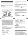
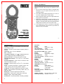
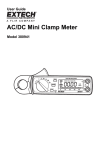
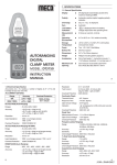
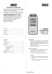
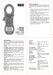
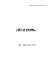
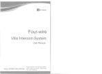
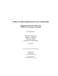
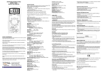
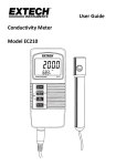
®
1. SPECIFICATIONS
Digital Clamp Meter
(TRMS)
Model : 2727
1.1 General Specifications
Display
: 3 ¾ digit liquid crystal display
(LCD) with a maximum reading
of 3999.
Polarity
: Automatic, positive implied,
negative polarity indication.
Overrange
: (OL) or (-OL) is displayed.
Zero
: Automatic.
Low battery indication
: “(+ -)” is displayed when the
battery voltage drops below the
operating level.
Measurement rate
: 2.5 times per second, nominal.
Operating Environment : 00C to 500C at < 70% relative
humidity.
Storage Temperature
: -200C to 600C, 0 to 80% R.H. with
battery removed from meter.
Accuracy
: Stated accuracy at 270C ± 50C,
<75% relative humidity.
Power
: Single standard 9 Volt battery
EVEREADY TYPE 216 or
Equivalent.
Battery life
: 200 hours typical with
carbon-zinc.
Dimension
2727 : 192mm(H)x82mm(W)x33mm(D).
Weight
2727 : 270grams approx.
Accessories
: One “K” type thermocouple,
one pair of test leads 9V battery
(installed), instruction manual.
Maximum Jaw Opening : 2727 : 30mm.
Instruction Manual
2
1
1.2 Electrical Specifications
DIODE TEST
AC CURRENT (True RMS)
Test Current
Accuracy
Open circuit volts
Overload protection
Range
Accuracy
Overload
Protection
40A
50/60Hz ± (2%rdg+4dgt)
40-500Hz ± (3.5%rdg+5dgt)
1000A
ac max.
400A/600A (2727)
40 - 500Hz ± (3.5%rdg+5dgt) for 1 min.
AC VOLTS (True RMS) (50 Hz - 500Hz)
Range
Resolution
Accuracy
Input lmpedance
Overload protection
400V,750V
100mV
± (2.9%rdg+4dgts)
10MV
1000V DC or 750V AC rms
FREQUENCY (Autoranging)
Ranges
Accuracy
Sensitivity
Overload Protection
1000V
1V
± (1.5%rdg+1dgt)
10MV
1000V DC or 750V AC rms
4kHz - 40kHz
± (1%rdg+2dgt)
100V rms min
500V DC or AC rms (50Hz-1KHz)
TEMPERATURE
Ranges
Resolution
Accuracy
DC VOLTS
Range
Resolution
Accuracy
Input lmpedance
Overload protection
1.0mA ± 0.6mA
± (3%rdg + 3dgt)
3.0V DC typical
500V DC or AC rms
- 200C ~ 7500C
10C
± (2.0% rdg + 3 dgts ) on
-200C ~ 5000C
± (3.0% rdg + 2 dgts ) on
5000C ~ 7500C
CONTINUITY
Audible indication
Overload protection
less than 100V
500V DC or AC rms
RESISTANCE
Range
Resolution
Accuracy
Open circuit voltage
Overload protection
3
400V, 400KV
100mV
± (1.5%rdg+3dgt)
0.6V DC (3.0V DC on 400V
range) 500V DC or AC rms
4
2. OPERATION
Before taking any measurements, read the safety information
section Always examine the instrument for damage, contamination
(excessive dirt, grease, ect.) and defects. Examine the test leads
for cracked or trayed insulation. If any abnormal conditions exist
do not make any measurements.
MAX. DATA HOLD SWITCH
The push switch (push Latch, Push Release) will hold the maximum
reading on the display. The display will update if a higher value is
measured. A “p” will appear in the display when this feature is
enabled.”
2.1 Current Measurements
1. Set the Function/Range switch on the highest 600A AC range.
2. Press the trigger to open transformer jaws and clamp onto one
conductor only. Read the current directly on the display. It is
recommenced that the conductor be placed at the center of the
closed jaws for maximum accuracy.
3. When the reading is lower than 400 counts, set the range switch
to the next lower range position. For maximum accuracy, select
the lower range possible without over ranging the meter.
2.2 Voltage Measurements
1. Connect the red test lead to the “ VV” jack and the black test lead
to the “COM” jack.
2. Set the Function/Range switch to the desired Voltage type (AC or
DC) and range. If magnitude of voltage is not known, set switch
to the highest range and reduce until a satisfactory reading is
obtained.
3. Connect the test leads to the device or circuit being measured.
4. For DC, a (-) sign is displayed for negative polarity; positive polarity
is implied.
2.3 Frequency Measurements
1. Set the Function/Range switch to the “Hz” position.
2. Connect the red test to the “VV” jack and the black test lead to
the “COM” jack.
3. Connect the test leads ro the point of measurements and read
the frequency from the display.
2.4 Temperature Measurements
WARNING : Remove test leads before measuring temperature
1. Set the Function/Range switch to the “0C” position.
2. Connect a k type thermocouple to the jack on the instrument.
Place the probe or thermocouple tip on or in the material to be
measured and take the temperature reading directly from the
display.
2.5 Diode Test
1. Connect the red test lead to the “VV” jack and black test lead 1o
the “COM” jack.
2. Set the Function/rRange switch to the diode position.
3. Turn off power to the circuit under test.
4. Touch probes to the diode. A forward-voltags drop is about 0.6V
(typical for a silicon diode.)
5. Reverse probes It the diode is good, display will be between
2.800V and 3.200V. If the diode is shorted, “.000” or another
number is displayed.
6. If the diode is open, display will be between 2.800V and 3.200V,
in both directions.
7. If the diode is measured in a circuit and a low reading is obtained
with both lead connections, the diode may be shunted by a
resistance of less than 1kV. In this case the diode must be
disconnected from the circuit for accurate tasting
2.6 Resistance and Continuity Measurements
1. Set the Function/Range switch to the desired resistance range
or continuity position.
2. Disconnect power from the equipment under test.
3. Connect the red test lead to the “VV” jack and the black test lead
to the “COM” jack.
4. Touch the probes to the test points. In ohms, the value indicated
in the display is the measured value of resistance. In continuity
test, the beeper sounds continuously if the resistance is less
than 100V.
6
5
®
3. MAINTENANCE
WARNING
Remove test leads before changing battery or performing any
servicing.
Battery Replacement
Power is supplied by a 9 volt “transistor” battery EVEREADY TYPE
216 or Equivalent. The “(+ -)” appears on the LCD display when
replacement is needed To replace the battery, remove the screw
from the meter and lift off the battery cover Remove the battery
from battery contacts and replace cover.
4. SAFETY INFORMATION
The following safety information must be observed to ensure
maximum personal safety during the operation of this meter :
1. Do not use the meter if the meter or test leads lock damaged, or
if you suspect that the meter is not operating properly.
2. This clamp meter is designed to take current measurements on
circuit with a maximum voltage difference of 500VAC between
any conductor and ground potential. Using the instrument for
current measurements on circuit above this voltage may cause
electric shock, instrument damage or damage lo the equipment
under test.
3. Turn off power to the circuit under test before cutting, unsoldering,
or breaking the circuit Small amounts of current can be dangerous.
4. Use caution when working above 60V DC or 30V AC rms. Such
voltages pose a shock hazard.
5. When using the probes, keep your fingers behind the finger guards
on the probes.
6. Measuring voltage which exceeds the limits of the clamp meter
may damage the meter and expose the operator to a shock
hazard. Always recognize the meter voltage limits as stated on
the meter.
7
CERTIFICATE OF CALIBRATION
We hereby cer tify that this product has been
calibrated and found to be in accordance
with the applicable SPECIFICATIONS and MECO
STANDARDS.
Accuracies of the standard equipment used in this
calibration are traceable to the National Standards.
MECO METERS PVT. LTD.
Block 9, Plot 270, 2nd Floor, Rup-Udey Niwas, Sion (E),
Mumbai - 400 022 (INDIA)
Correspondance Address :
Plot No. EL-1, MIDC Electronic Zone, TTC Industrial Area,
Mahape, Navi Mumbai - 400710 (INDIA)
Tel : 0091-22-27673311-16, 27673300 (Board)
Fax : 0091-22-27673310, 27673330
E-mail : [email protected] Web : www.mecoinst.com
SR. NO
: ___________________________
CHECKED BY : ___________________________
DATE
: ___________________________
MODEL NO
: ___________________________
8
®
1. SPECIFICATIONS
1.1 General Specification
DIGITAL
CLAMP
METER
MODEL :
2025-Hz TRMS
Display
n
3¾ digit liquid crystal display (LCD) with a
maximum reading of 3999.
Polarity
n
Automatic, positive implied, negative polarity
indication.
Overrange
n
(OL) or (-OL) is displayed.
Zero
n
Automatic.
Low battery
indication
n
“
” is displayed when the battery
voltage drops below the operating level.
Measurement
rate
n
3 times per second, nominal.
Operating
Environment
n
0°C to 50°C at < 70% relative humidity.
Storage
Temperature
n
-20°C to 60°C, 0 to 80% R.H. with battery
removed from meter.
Power
n
Two 1.5V ‘AAA’ Size Battery
Battery life
n
200 hours typical
Dimensions
n
250mm X 98mm X 35mm
Weight
n
400 grams approx.
Accessories
n
One pair of test leads, instruction manual,
1.5V batterys (installed), Carring Case,
Maximum Jaw
Opening
n
55mm
INSTRUCTION
MANUAL
1
1.2 Electrical Specification
Accuracies are ± (% reading + number of digits) at 27 ± 5°C and
humidity of less than 75% RH.
AC CURRENT (True RMS)
Range
Accuracy
40A
400A / 1000A
50-60Hz ±(3% rdg+ 6dgt)
40-500Hz ±(3.5% rdg+ 5dgt)
Overload
Protection
1000A AC Max.
for 1 minute
DC VOLTAGE (Auto Ranging)
2
Resolution
: 0.1V to 0.01MV
Test Current
: 0.7mA on 400V, 0.1mA on 4KV,
30µA on 40KV, 4µA on 400KV
Overload Protection : 500V DC/AC
Continuity Check
Threshold Level
: 40V Approx.
Response Time
: 1m Sec. Approx.
Open Circuit Voltage
: 0.4V Approx.
Indication
: ‘ ’ is displayed on LCD and buzzer sounds
at continuity.
: 500V DC / AC
Ranges
: 4V, 40V, 400V, 1000V
Accuracy
: ± (1% of rdg + 2 dgt)
Overload Protection
Resolution
: 1mV to 1V
Diode Test
Input Impedance
: 10MV on all ranges except,
11MV on 4V
Measurement Current : 1.0 ± 0.6 mA Approx.
Open Circuit Voltage
: 0.4V Approx.
Overload Protection : 1200V DC/800V AC
Overload Protection
: 500V DC / AC
AC VOLTAGE (Auto Ranging) 40-500Hz
Frequency (Auto Ranging)
Range
: 4V, 40V, 400V, 750V
Range
: 10.00Hz, 50.00Hz, 500.0Hz, 5.000kHz,
Accuracy
: ± (1.5% rdg + 6 dgt)
Resolution
: 1mV to 1V
Accuracy
: ± (0.5% rdg + 5 dgt)
Input Impedance
: 10MV on all ranges except, 11MV on 4V
Sensitivity
: 3V
50.00kHz, 500.0kHz
Overload Protection : 1200V DC/800V AC
Overvoltage Protection : 200V DC or AC peak
RESISTANCE (Auto Ranging)
% Duty Cycle (Auto Ranging)
Range
: 400V, 4KV, 40KV, 400KV, 4MV, 40MV
Range
: 1% to 90%
Accuracy
: ± (2.5% of rdg + 3 dgt)
Accuracy
: ± (0.5% rdg + 5 dgt)
Resolution
: 0.1%
Overvoltage Protection : 200V DC or AC peak
3
4
2.2 Voltage Measurements
2. OPERATION
Before taking any measurements, read the safety information section.
Always examine the instrument for damage, contamination (excessive
dirt, grease, etc.) and defects. Examine the test leads for cracked or
frayed insulation. If any abnormal conditions exist do not attempt to make
any measurements.
SELECT BUTTON
In ACV Range it will select ACV / Hz/Duty function. In V/ / range it
will select resistance or diode or countinuity function. In Hz it will select
Hz/Duty function.
1.
Connect the red test lead to the “VV” jack and the black test lead
to the “COM” jack.
2.
Set the Function/Range switch to the desired Voltage type
(AC or DC)
3.
Connect the test leads to the device or circuit being measured.
4.
For DC, a (-) sign is displayed for negative polarity; positive
polarity is implied.
2.3 Resistance Measurements
1.
DATA HOLD BUTTON
Connect red test lead to the “VV” jack and black test lead
to the “COM” jack.
Press Data Hold button to toggle in and out of Data Hold mode, In the
Data Hold mode, the “ HOLD ” annunciator is displayed.
2.
Set function / Range switch to V/
2.1
Current Measurements
3.
1.
Set the Function / Range switch to the highest 1000A AC
range.
If the resistance being measured is connected to a circuit,
turn off power to the circuit being tested and discharge all
capacitors.
2.
Press the trigger to open transformer jaws, clamp onto one
conductor only and release trigger. Jaws should be completely
closed. Read the current directly on the display. It is
recommended that the conductor be placed at th e center of
the closed jaws for maximum accuracy (Fig. - 1).
4.
Connect test leads across the resistance being measured.
When measuring high resistance, be sure not to contact
adjacent points even if insulated because some insulators
have a relatively low insulation resistance, causing the measured
resistance to be lower than the actual resistance.
5.
Read resistance value on digital display. If a high resistance
vaiue is shunted by a large value of capacitance allow display to
stabilize.
7
3
/
position.
2.4 Diode Test
Fig. 1
1.
Connect the red test lead to the “VV” jack and black test lead
to the “ COM ” jack.
2.
Set the Function / Range switch to the V/
“ ” by pressing select key.
When the reading is lower than 400 counts, set the range
switch to the next lower range position. For maximum
accuracy, select the lowest range possible without over
ranging the meter.
3.
Turn off power to the circuit under test.
4.
Touch probes to the diode. A forward-voltage drop is about
0.6V (typical for a silicon diode).
2.6b “ACV” position (For line frequency measurement.)
5.
If the digital display reads overrange “ OL ”, reverse the lead
connections. The placement of the test leads when the forward
reading is displayed indicates the orientation of the diode. The
red lead is positive and the black lead is negative. If overrange
“ OL ” is displayed with both lead connections, the junction is
open. If a low reading (less than 1000) is obtained with both
lead connections, the junction is shorted internally or (if
junction is measured in a circuit) the junction is shunted by a
resistance less than 1KV. In the letter case the junction must
be disconnected from the circuit in order to verify its operartion.
3.
5
2.5 Continuity Measurement
In continuity test, the beeper sounds continuously, if the
resistance is less than 40V.
2.6 Frequency & Duty Cycle Measurement
There are 2 positions for Frequency & Duty cycle measurements.
a) “Hz” position (Not for line frequency measurement.)
b) “ACV” position. (for line frequency measurement)
2.6a “Hz” position (Not for line frequency measurement.)
Sensitivity
Frequency Range
Duty Cycle
Overvoltage Protection
:
:
:
:
3V
10Hz to 500kHz
1% to 90%
200V DC or AC peak
1. Connect test lead to “VV” and “COM” terminal.
2. Set rotary switch to “Hz” posotion.
3. Select Frequency or Duty cycle by pressing “Select” key.
4. Connect the test leads across the source or load under
measurement.
7
/
position, select
6
Sensitivity
Frequency Range
Duty Cycle
Overvoltage Protection
:
:
:
:
2V
40Hz to 500Hz
10% to 90%
1000V DC or 750V AC peak
1. Connect test lead to “VV” and “COM” terminal.
2. Set rotary switch to “ACV” posotion.
3. Select Frequency or Duty cycle by pressing “Select” key.
4. Connect the test leads across the source or load under
measurement.
3. MAINTENANCE
WARNING
Remove test leads before changing battery or servicing.
Battery Replacement
Power is supplied by two 1.5V ‘AAA’ size battery or Equivalent.
The “
” appears on the LCD display when replacement is needed.
To replace the battery, remove the screw from the battery cover and lift
off the battery case. Remove the batterys & repleced with new batterys.
4. SAFETY INFORMATION
The following safety information must be observed to ensure maximum
personal safety during the operation of this meter:
1. Do not use the meter if the meter or test leads look damaged,
or if you suspect that the meter is not operating properly.
2. This Clamp Meter is designed to take current measurements
on circuits with a maximum voltage difference of 500VAC
between any conductor and ground potential. Using the
instrument for current measurements on circuits above this
voltage may cause electric shock, instrument damage or
damage to the equipment under test.
8
Before measuring current make certain the test leads are
removed from the instrument.
3. The instrument is protected for overload upto 500 VAC for 1
minute. Do not take current readings on circuits where the
maximum current potential is not known.
N OT E
○
○
○
○
○
○
○
○
○
○
○
○
○
○
○
○
○
○
○
○
○
○
○
○
○
○
○
○
○
○
○
○
Do not exceed the maximum currents that this instrument is
designed to measure.
○
○
○
○
○
○
○
○
○
○
○
○
○
○
○
○
○
○
○
○
○
○
○
○
○
○
○
○
○
○
○
○
4. Turn off power to the circuit under test before cutting,
unsoldering, or breaking the circuit. Small amounts of current
can be dangerous.
○
○
○
○
○
○
○
○
○
○
○
○
○
○
○
○
○
○
○
○
○
○
○
○
○
○
○
○
○
○
○
○
5. Use caution when working above 60V DC or 30V AC rms.
Such voltages pose a shock hazard.
○
○
○
○
○
○
○
○
○
○
○
○
○
○
○
○
○
○
○
○
○
○
○
○
○
○
○
○
○
○
○
○
○
○
○
○
○
○
○
○
○
○
○
○
○
○
○
○
○
○
○
○
○
○
○
○
○
○
○
○
○
○
○
○
○
○
○
○
○
○
○
○
○
○
○
○
○
○
○
○
○
○
○
○
○
○
○
○
○
○
○
○
○
○
○
○
○
○
○
○
○
○
○
○
○
○
○
○
○
○
○
○
○
○
○
○
○
○
○
○
○
○
○
○
○
○
○
○
○
○
○
○
○
○
○
○
○
○
○
○
○
○
○
○
○
○
○
○
○
○
○
○
○
○
○
○
○
○
○
○
○
○
○
○
○
○
○
○
○
○
○
○
○
○
○
○
○
○
○
○
○
○
○
○
○
○
○
○
○
○
○
○
○
○
○
○
○
○
○
○
○
○
○
○
○
○
○
○
○
○
○
○
○
○
○
○
○
○
○
○
○
○
○
○
○
○
○
○
○
○
○
○
○
○
○
○
○
○
○
○
○
○
○
○
○
○
○
○
○
○
○
○
○
○
○
○
○
○
○
○
○
○
○
○
○
○
○
○
○
○
○
○
○
○
○
○
○
○
○
○
○
○
○
○
○
○
○
○
○
○
○
○
○
○
○
○
○
○
○
○
○
○
○
○
○
○
○
○
○
○
○
○
○
○
○
○
○
○
○
6. When using the probes, keep your fingers behind the finger
guards on the probes.
7. Measuring voltage which exceeds the limits of the clamp meter
may damage the meter and expose the operator to a shock
hazard. Always recognize the meter voltage limits as stated
on the front of the meter.
9
N OT E
10
○
®
○
○
○
○
○
○
○
○
○
○
○
○
○
○
○
○
○
○
○
○
○
○
○
○
○
○
○
○
○
○
○
○
○
○
○
○
○
○
○
○
○
○
○
○
○
○
○
○
○
○
○
○
○
○
○
○
○
○
○
○
○
○
○
○
CERTIFICATE OF CALIBRATION
○
○
○
○
○
○
○
○
○
○
○
○
○
○
○
○
○
○
○
○
○
○
○
○
○
○
○
○
○
○
○
○
○
○
○
○
○
○
○
○
○
○
○
○
○
○
○
○
○
○
○
○
○
○
○
○
○
○
○
○
○
○
○
○
○
○
○
○
○
○
○
○
○
○
○
○
○
○
○
○
○
○
○
○
○
○
○
○
○
○
○
○
○
○
○
○
○
○
○
○
○
○
○
○
○
○
○
○
○
○
○
○
○
○
○
○
○
○
○
○
○
○
○
○
○
○
○
○
○
○
○
○
○
○
○
○
○
○
○
○
○
○
○
○
○
○
○
○
○
○
○
○
○
○
○
○
○
○
○
○
○
○
○
○
○
○
○
○
○
○
○
○
○
○
○
○
○
○
○
○
○
○
○
○
○
○
○
○
○
○
○
○
○
○
○
○
○
○
○
○
○
○
○
○
○
○
○
○
○
○
○
○
○
○
○
○
○
○
○
○
○
○
○
○
○
○
○
○
○
○
○
○
○
○
○
○
○
○
○
○
○
○
○
○
○
○
○
○
○
○
○
○
○
○
○
○
○
○
○
○
○
○
○
○
○
○
○
○
○
○
○
○
○
○
○
○
○
○
○
○
○
○
○
○
○
○
○
○
○
○
○
○
○
○
○
○
○
○
○
○
○
○
○
○
○
○
○
○
○
○
○
○
○
○
○
○
○
○
○
○
○
○
○
○
○
○
○
○
○
○
○
○
○
○
○
○
○
○
○
○
○
○
○
○
○
○
○
○
○
○
○
We hereby certify that this product has been
calibrated and found to be in accordance with
the applicable SPECIFICATIONS and MECO
STANDARDS.
Accuracies of the standard equipment used in
this calibration are traceable to the National
Standards.
MECO METERS PVT. LTD.
Block 9, Plot 270, 2nd Floor, Rup-Udey Niwas, Sion (E),
Mumbai - 400 022 (INDIA)
Correspondance Address :
Plot No. EL-1, MIDC Electronic Zone, TTC Industrial Area,
Mahape, Navi Mumbai - 400710 (INDIA)
Tel : 0091-22-27673311-16, 27673300 (Board)
Fax : 0091-22-27673310, 27673330
E-mail : [email protected] Web : www.mecoinst.com
SR. NO
: ________________________________
CHECKED BY : ________________________________
11
○
DATE
: ________________________________
MODEL NO
: ________________________________12
®
SAFETY INFORMATION
The following safety information must be observed to insure
maximum personal safety during the operation at this
meter:
1. Do not use the meter if the meter or test leads look
damaged, or if you suspect that the meter is not
operating properly.
2. Use caution when working above 60V dc or 30V ac
rms. Such voltages pose a shock hazard.
3. When Using the probes, keep your fingers behind the
finger guards on the probes.
4. Measuring voltage which exceeds the limits of the
clamp meter may damage the meter and expose the
operator to a shock hazard. Always recognize the meter
voltage limits as stated on the front of the meter.
5. If the equipment is used in a manner not specified
by the manufacturer, the protection provided the
equipment may be impaired.
DIGITAL
CLAMP ON
METER
MODEL : 3636
USER MANUAL
1
2
SPECIFICATIONS
DC VOLTS
Display : 3½ digit liquid crystal display (LCD) with a maximum reading of 1999.
Polarlty : Automatic, positive implied, negative polarity indication.
Ranges
Accuracy
Input Impedance
Overload protection
Overrange : (OL) or (-OL) is displayed.
AC VOLTS (True RMS) (50Hz - 500Hz)
Zero : Automatic.
Ranges
Accuracy
Input Impedance
Overload protectlon
Low battery indlcation : the “
” is displayed when the
battery voltage drops below the operating level.
Measurement rate : 2.5 times per second, nominal.
Operating Environment : 00C to 400C at < 70% relative
humidity.
0
0
Storage Temperature : -20 C to 60 C, 0 to 80% R.H. with
battery removed from meter.
Accuracy : Stated accuracy at 230C ± 50C, <75% relative
humidity.
Safety : According to EN61010-1 protection class II overvoltage category (CAT III 600V) pollution degree 2.
Clamp jaw : According ro EN61010-2-032 CAT IV 600V.
Power : single standard 9-volt battery, NEDA 1604, JIS
006P, IEC 6F22.
Battery life : 200 hours typical with carbon-zinc,
Dimensions : 250mm (H) x 100mm (W) x 46mm (D).
Weight : Approx. 380g including battery.
: 600V
: ±(0.5% rdg + 1dgt)
: 10MV
: 600VDC or AC rms
: 200V, 600V
: ±(1.2% rdg + 10dgts)
: 10MV
: 600VDC or AC rms
RESISTANCE
Rangea
Accuracy
Open circuit volts
Overload protection
: 2KV, 200KV
: ±(1.2% rdg + 1dgt)
: 0. 3Vdc
: 600VDC or AC rms
FREQUENCY (Autoranging)
Ranges
Accuracy
: 2KHz, 20KHz
: ±(0.1% rdg + 3dgts)
on all ranges
Sensitivity
: 80Vrms min
Overload protection : 600VDC or AC rms
CONTINUITY
Audible lndication : less than 30V on 2KV range
Overload protection : 600VDC or AC rms
Accessories : One pair test leads, 9V battery (installed).
3
4
DIODE TEST
MAX HOLD Button :
Test current : 1.0mA ± 0.6mA
Accuracy : ±(6.0% rdg + 3dgts)
Open circuit volts : 3.0Vdc typical
Audible Indication : < 30mV
Overload protection : 600VDC or AC rms
Press “ MAX ” button to toggle in and out of MAX Hold
mode (holding the highest absolute reading). In the MAX
Hold mode, the “ MAX ” annunciator is displayed.
AC CURRENT (True RMS) (Put conductor at the
center of the jaws)
Press “PEAK” button to toggle in and out of PEAK Hold
mode. In the PEAK Hold mode, the “ P ” annunciator is
displayed. {Accuracy : ± [10% (readind -residual offset) +
10dgts], effect reading : 80~2000}
Ranges : 20A, 200A, 1000A
Accuracy :
±(1.5%rdg + 10dgts) on all ranges (50Hz/60Hz)
±(3.5%rdg + 10dgts) on 700A(40Hz/500Hz)
±(2.0%rdg+ 10dgts) on700A to 1000A(50Hz/60Hz)
Overload protection : 1000Aac max. for 1 minute
OPERATION
Before taking any measurements, read the Safety
Information Section. Always examine the instrument for
damage, contamination (excessive dirt, grease, etc.) and
defects. Examine the test leads for cracked or frayed
insulation. If any abnarmal conditions exist do not attempt
to make any measurements.
H Button : Press “ H ” button to toggle in and out of
DATA Hold mode, In the DATA Hold mode, the “ H ”
annunciator is displayed. (The DATA Hold mode may be
exited when changing function.)
5
3. When the reading is lower than 200 counts, set the
range switch to the next lower range position. For
maximum accuracy, select the lower range possible
without overranging the meter.
Resistance Measurements
1. Set the Function/Range switch to the desired resistance
range.
2. Remove power from the equipment under test.
3. Connect the red test lead to the “ + ” jack and the black
test lead to the “COM” jack.
4. Touch the probes to the test points. In ohms, the value
indicated in the display is the measured value of
resistance.
WARNING
The accuracy of the functions might be slightly affected,
when exposed to a radiated electromagnetic field
environment, eg, radio, telephone or similar.
Frequency Measurements
1. Set the Functian/Range switch to the Hz position.
2. Connect the red test lead to the “ + ” jack and the black
test lead to the “COM” jack.
3. Connect the test leads to the point of measurement
and read the frequency from the display.
Continuity Measurements
1. Set the Function/Range switch to the “
/ 2KV” position.
2. Touch the probes to the test points. the beeper sounds
continuously, if the resistance is less than 30V.
7
Current and Hz ranges without MAX HOLD function.
PEAK HOLD Button : (only current ranges 40-60Hz)
Voltage Measurements
1. Connect the red test lead to the “V” jack and the black
test lead to the “COM” jack.
2. Set the Function/Range switch to the desired Voltage
type (AC or DC) and range. If magnitude of voltage is
not known, set switch to the highest range and reduce
until a satisfactory reading is obtained.
3. Connect the test leads to the device or circuit being
measured.
4. For dc, a (-) sign is displayed for negative polarity,
positive polarity is implied.
Curreat Measurements
1. Set the Function/Range switch to the highest 1000A
ac range.
2. Press the trigger to open transformer jaws and clamp
onto one conductor only, Read the current directly on
the display. It is recommended that the conductor be
placed at the center of the closed jaws for maximum
6
accuracy.
Diode Tests
1. Connect the red test lead to the “ + ” jack and the black
test lead to the “COM” jack.
2. Set the Function/Range switch to the “
” position.
3. Turn off power to the circuit under test.
4. Touch probes to the diode. A forward-voltage drop is
about 0.6V (typical for a silicon diode).
5. Reverse probes. If the diode is goad, “OL” is displayed.
If the diode is shorted, “.000” or another number is
displayed.
6. If the diode is open, “OL” is displayed in both directions.
7. If the junction is measured in a circuit and a low reading
is obtained with both lead connections, the junction may
be shunted by a resistance of less than 1kV. In this
case the diode must be disconnected from the circuit
for accurate testing,
MAINTENANCE
WARNING : Remove test leads before changing battery
or performing any servicing.
Battery Replacement
Power is supplied by a 9 volt “transistor” battery. (NEDA
1604, IEC 6F22). The “
” appears on the LCD display
when replacement is needed. Ta replace the battery,
remove the two screws from the back of the meter and lift
off the battery cover. Remove the battery from battery
contacts.
Cleaning
Periodically wipe the case with a damp cloth and
detergent, do not use abrasives or solvents.
8
®
NOTE
○
○
○
○
○
○
○
○
○
○
○
○
○
○
○
○
○
○
○
○
○
○
○
○
○
○
○
○
○
○
○
○
○
○
○
○
○
○
○
○
○
○
○
○
○
○
○
○
○
○
○
○
○
○
○
○
○
○
Certificate of Calibration
○
○
○
○
○
○
○
○
○
○
○
○
○
○
○
○
○
○
○
○
○
○
○
○
○
○
○
○
○
○
○
○
○
○
○
○
○
○
○
○
○
○
○
○
○
○
○
○
○
○
○
○
○
○
○
○
○
○
○
○
○
○
○
○
○
○
○
○
○
○
○
○
○
○
○
○
○
○
○
○
○
○
○
○
○
○
○
○
○
○
○
○
○
○
○
○
○
○
○
○
○
○
○
○
○
○
○
○
○
○
○
○
○
○
○
○
○
○
○
○
○
○
○
○
○
○
○
○
○
○
○
○
○
○
○
○
○
○
○
○
○
○
○
○
○
○
○
○
○
○
○
○
○
○
○
○
○
○
○
○
○
○
○
○
○
○
○
○
○
○
○
○
○
○
○
○
○
○
○
○
○
○
○
○
○
○
○
○
○
○
○
○
○
○
○
○
○
○
○
○
○
○
○
○
○
○
○
○
○
○
○
○
○
○
○
○
○
○
○
○
○
○
○
○
○
○
○
○
○
○
○
○
○
○
○
○
○
○
○
○
○
○
○
○
○
○
○
○
○
○
○
○
○
○
○
○
○
○
○
○
○
○
○
○
○
○
○
○
○
○
○
○
○
○
○
○
○
○
○
○
○
○
○
○
○
○
○
○
○
○
○
○
○
○
○
○
○
○
○
○
○
○
○
○
○
○
○
○
○
○
○
○
○
○
○
○
○
○
○
○
○
○
○
○
○
○
○
○
○
○
○
○
○
○
○
○
○
○
○
○
○
○
○
○
○
○
○
○
○
○
○
○
○
○
○
○
○
○
○
○
○
○
○
○
○
○
○
○
○
○
○
○
○
○
○
○
9
○
We hereby cer tify that this product has been
calibrated and found to be in accordance
with the applicable SPECIFICATIONS and
STANDARDS.
Accuracies of the standard equipment used in
this calibration are traceable to the National
Standards.
MECO METERS PVT. LTD.
Block 9, Plot 270, 2nd Floor, Rup-Udey Niwas,
Sion (E), Mumbai - 400 022 (INDIA)
Correspondance Address :
Plot No. EL-1, MIDC Electronic Zone, TTC Industrial
Area, Mahape, Navi Mumbai - 400710 (INDIA)
Tel : 0091-22-27673311-16, 27673300 (Board)
Fax : 0091-22-27673310, 27673330
E-mail : [email protected]
Web : www.mecoinst.com
SR. NO.
:
CHECKED BY :
DATE
:
MODEL NO.
:
10
NOTE
NOTE
○
○
○
○
○
○
○
○
○
○
○
○
○
○
○
○
○
○
○
○
○
○
○
○
○
○
○
○
○
○
○
○
○
○
○
○
○
○
○
○
○
○
○
○
○
○
○
○
○
○
○
○
○
○
○
○
○
○
○
○
○
○
○
○
○
○
○
○
○
○
○
○
○
○
○
○
○
○
○
○
○
○
○
○
○
○
○
○
○
○
○
○
○
○
○
○
○
○
○
○
○
○
○
○
○
○
○
○
○
○
○
○
○
○
○
○
○
○
○
○
○
○
○
○
○
○
○
○
○
○
○
○
○
○
○
○
○
○
○
○
○
○
○
○
○
○
○
○
○
○
○
○
○
○
○
○
○
○
○
○
○
○
○
○
○
○
○
○
○
○
○
○
○
○
○
○
○
○
○
○
○
○
○
○
○
○
○
○
○
○
○
○
○
○
○
○
○
○
○
○
○
○
○
○
○
○
○
○
○
○
○
○
○
○
○
○
○
○
○
○
○
○
○
○
○
○
○
○
○
○
○
○
○
○
○
○
○
○
○
○
○
○
○
○
○
○
○
○
○
○
○
○
○
○
○
○
○
○
○
○
○
○
○
○
○
○
○
○
○
○
○
○
○
○
○
○
○
○
○
○
○
○
○
○
○
○
○
○
○
○
○
○
○
○
○
○
○
○
○
○
○
○
○
○
○
○
○
○
○
○
○
○
○
○
○
○
○
○
○
○
○
○
○
○
○
○
○
○
○
○
○
○
○
○
○
○
○
○
○
○
○
○
○
○
○
○
○
○
○
○
○
○
○
○
○
○
○
○
○
○
○
○
○
○
○
○
○
○
○
○
○
○
○
○
○
○
○
○
○
○
○
○
○
○
○
○
○
○
○
○
○
○
○
○
○
○
○
○
○
○
○
○
○
○
○
○
○
○
○
○
○
○
○
○
○
○
○
○
○
○
○
○
○
○
○
○
○
○
○
○
○
○
○
○
○
○
○
○
○
○
○
○
○
○
○
○
○
○
○
○
○
○
○
○
○
○
○
○
○
○
○
○
○
○
○
○
○
○
○
○
○
○
○
○
○
○
○
○
○
○
○
○
○
○
○
○
○
○
○
○
○
○
○
○
○
○
○
○
○
○
○
○
○
○
○
○
○
○
○
○
○
○
○
○
○
○
○
○
○
○
○
○
○
○
○
○
○
○
○
○
○
○
○
○
○
○
○
○
○
○
○
○
○
○
○
○
○
○
○
○
○
○
○
○
○
○
○
○
○
○
○
○
○
○
○
○
○
○
○
○
○
○
○
○
○
○
○
○
○
○
○
○
○
○
○
○
○
○
○
○
○
○
○
○
○
○
○
○
○
○
○
○
○
○
○
○
○
○
○
○
○
○
○
○
○
○
○
○
○
○
○
○
○
○
○
○
○
○
○
○
○
○
○
○
○
○
○
○
○
○
○
○
○
○
○
○
○
○
○
○
○
○
○
○
○
○
○
○
○
○
○
○
○
○
○
○
○
○
○
○
○
○
○
○
○
○
○
○
○
○
○
○
○
○
○
○
○
○
○
○
○
○
○
○
○
○
○
○
○
○
○
○
○
○
○
○
○
○
○
○
○
○
○
○
○
○
○
○
○
○
○
○
○
○
○
○
○
○
○
○
○
○
○
○
○
○
○
○
○
○
○
○
○
○
○
○
○
○
○
○
○
○
○
○
○
○
○
○
○
○
○
○
○
○
○
○
○
○
○
○
○
○
○
○
○
○
○
○
○
○
○
○
○
○
○
○
○
○
○
○
○
○
○
○
○
○
○
○
○
○
○
○
○
○
○
○
○
○
○
○
○
○
○
○
○
○
○
○
○
○
○
○
○
○
○
○
○
○
○
○
○
○
○
○
○
○
○
○
○
○
○
○
○
○
○
○
○
○
○
○
○
○
○
○
○
○
○
○
○
○
○
○
○
○
○
○
○
○
11
○
12
○