1
Denway
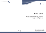
Four-wire
Villa Intercom System
User Manual
VilLA INTERCOM SYSTEM
Please read this user manual carefully
betere using the preducts. Please keep
It for future reference.
~ ~
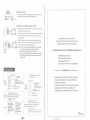
I. CompClllcnts
Option of door station
-
----------- - --------------------------- ----------------- --
F5010
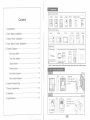
Content
1. Components· ···· · ·········· ······ ····· ····· · ·················· 1
2. Ooor Station Installation .. ·· .... ·· .... · .. ····· .... · .. ·· .. 1
3. Indoor Phone Installation· .... · .. ···· .. · .. · .. ·· .... ·· .. ···6
4. Ooor Station Switch Installation .. ·· .... · .. ··· · .. ·· .... · 6
5. System Diagram'" .. , .............. , ..................... 7 One door station···· ·· · . , .............. . ........ .......... 7 Two door stations'" ................... ,............. ···8 Signal unlock· ···· ·· ······ ·· ····· ······· ······,· ········ ····· 9
FSS60
F5S50
F5050
F5S70
F5G91/ F5G92
[I ~ m [·~·I
I~II ~
=0
: ... 2.
ir
Option of indoor phone
------- -
-r-------------r------------ -r - ------ -- - - ~ --- - --- --- - r-- - -----
F3010
:
F3030
:
F3110
:
F3120
:
F3190
J
F3H40
g! ~ : g [E B! ~
,
Other fittings
[j P~~;r~~~~y ---:-ü-ö~;~t;ti~~-~~tt~h:Ö- ~d~~~ph~~~-~~~;~~~~--:-Ö-Ü;;~~~~~~l
~
Indoor phone M\h bu\~...,
power supply do9sn'[ usa
Ihos.
i:I
0
••
I
*
g ..
~
~g:i W
mm'rn:
I
-=
I
,
1
,
I
I
I
:
'
Thls devlce Is used In "!wo :
door staUons' system. !
0' 0
0
~ 0
'\)
"... ~ el W
-=
I
..
.
. ":.
..
"I
.
:;;;:
0
(Note) Th1J power supply varles In different countrles, please check wlth us before ordering.
Power unlock· ...... ·· .. ··· · .... ····· ...... ·.. ···· .... ··· .... 9
Exit button diagram .. ,........ ,........ ..... .... .... ...... 9 Unit: mm
45 .5
Card module diagram' ......... ·····························9 6. System Programming············ ················ ·· ,·, ··· ··· 9
7. Product Appearance············ ······· ······················· 10
--60.s.-.
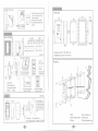
CD DoorlWall
® Door station front
o
1
IT ® Door station bracket
"01B I
;l~ Screw
1<>0
T
L
(!J a
8. Operation······················· ,', · ····· · ··· ······ ··· ········· 11
Unitmm
9. Specifications···· ·· ··········································12
29--1
r-60---l
'i Ooor/v\IaJI
Doorslatil
Doorstatil
•
..... _ - - - - - - - - - - - - - - .....
,I)Screw
- 76
f.$J
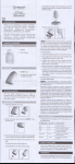
>11';)< Ghange name pJate
1 .Insert lhe screw driver in Ihe
notch. Tum and push lhe
Name plate
plasbc upwards
.
•
I
~(g]
Bunt-In Installation
D1
_::::J
2.Change the name plate.
3.Pullhe plastic back to the
Plaslic
D2
Dimensions
132
150
~r;n
•
0
:::::::i:::"
groove.
:::::::::::::
~II
00
N~
j'
II~~II
I I
64
106
l'
0
~
N
@I~ILI. Iron door
...
130
68.5
126X42
Product size: 272 x 1SO X 68.5 mm Unit: mm
nCa ~~II
(0'
1 Push lhe right edge
and move 10 right.
Gi DooriWeJl
® Door station front
@ DOOf station brad<.et
(I) Screw
~ Plugs
-9
Mounting
Plaslic
2.Takeoff
the plasUc.
3.Change the
nameplate
-----------------------
4 Then insert the righl
edge into sideling
~
Name plate
Installation size: 254 X 132 X 64 mm ~
t1P
5.Push Ihe left edge
and mave to left.
r~o--
Unit: mm
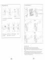
F5S70
~
fTlMw1g ~!NI
the wIrB .".,.q, 1118 tu.
01 pe pIe:to. . . , ~
• ~ door &laIion l8IITftII
enI gIUe hI pe . - on
hI daCI' ....... .-pIßII
@
"''-&.
CDWali
21 Door station front
I Saew
> <
@PC piste
@Door station front
@Door staUon bracket
'lJPlastlc pipe
~Screw
@Anti-dlsmantle screw
> <
Camera Adjustment
Changing Name Tag
@:.J. q "\ :=J
..' 11
p' •
•
Hmmmli
00
n1
C>
0
•
•
~
lmmmm
Name lag
[D]
0
•
•
"".
3. Take out the name lag.
1. Push the right edge 2. Take off the plastic.
S· for left and right
.-.0)0)
--1=
~
and move 10 right.
Down
•
•
mm~mH
ltLrIc>
&;°1 c> o
00
~o
~~gmmm
00 c>
•
~
•
o
•
1-
_
. ____ . _ . _
. _._.-
-
____ • _ _ _
-
_
. -
_
.-
-
Left 4. Put the name lag
in the plastlc.
A: for up and down
)? '.
o. ~
EJ
00
Plastic
[ill
§§ll,'§
5 Insert the rlght
6.Push the left edge
edge inlo sideling.
and move 10 left.
I
_"" ___ . -
I
-
_._ . -
__
.
~
,
_
.
_.-
_
. -
-
_ ._._._ . __
_
Right
7. Finish.
~)
~~~
Lh. Installation tips
• Don't Install door station near humid ,stove, and dusty condition.
• Mlnd the installation size while produclng a groove for the back cover.
• Control the depth of the groove carefully so thai it is the same as the one of lhe back cover. • There are waterproof silicon sheet attached on the dOOf stalion's back side, please install the door station 10 the smooth wall 10 guarantee the waterproof functlon • We suggesl the installation height of 1400mm. Also consider otherfactors such as the
angle of view and handicapped access.
> <
> <
:ft
lill __
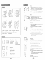
Power supply ~
Bracket
Unit:mm
Size: [g]
[QI D
li:Q5m 1~~8~ä
[EJ
~~~~
CJ 220X150X25
60mm
B
220X203X63
Method 1
I
Method 2
~,.
)
216X142X23
..
185X120X31
60mm
237X158X44
202X80X67
Method 1
Method 2
1
Lock
JII
f
Door station
Power supply ~
~
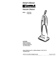
Wiring suggestion:
Wlrtng dlstance from door stalion to the last
Indoorphone should be less than 100m.
1. If djstance ~ 50m, use quad cable, with the
single wire resJstance <4 Cl • Recommend
RW4 XO.75 wlre.
2. tf distance>50m, use 3-core cable and
coaxlak:able, wllh the single wlre resistance
<40. Recommend RW3 x 1.0 and SYV-75 wire. 1) VDOOR, AUDIO, GND tannlnal use 3-core
cable.
2) VIDEO, GND tenninal usa coaxial cable.
_~ii~
~
Indoor phone
~
Indoor phone
D
~ ~
Power supply ~
---
o
co
c
@
000000000
66mm
91mm
E
E
t)]
. '
r
<»
<0
@T I
r ... , ... '
-
J"~ .
I
_
VDOOR
DCOM AUDIO
DNO GND
DNC VIDEO
--',
L - -_ _ _U
.0
I
AUDIO
GND
•
•
Off
150
ON
Vdao
I GNDD~ )U ~
The wiring between indoor
phon es must be conn~cted _
hand In hand, as the nght ,--~-r
shows.
: ::
L-__diagrams
~~______________
, , ,
, ,
I
•
>(;,1< It
,
I
[Note] 1. system can connect
wlth 1-4lndoor
r] VDOOR
I
,
: '-- U AUDIO
phones.
2. Tb. last Indoor phons 's
:---- UGND
video fflatchlng Jumper :------ nVIDEO
should be -ON-.
Indoor phone terminal
(Last one)
>ftJ<
'I?
:.
•
Vdao
Indoor phone terminal
::lj
,
I
~
VDOOR AUDID
GND
VIDEO
-J: : :
1. Don't install the device in wal areas.
2. Keep away from direct heat.
3. Don'! clean the device with wet towels or harsh cleaning agents. 4 Da not disassemble the producllf failure occurs contact your service provider r -_
=,
_
..
Power supply ~
r
~ Installation Tips
~
~
Indoor phone terminal
Door station terminal
. ·0
)
U
r+tMUVIDEO [
• • -lI
-
~
~
~
OFf
750
ON
Power unlock
Signal unlock (Nole: 1h,.wa1 01 unloclu"ll needs :;eparale _rsupply)
Ne connection
Power supply ~
Lock
~
L07>:t 2 I
ß"
Power supply
~
~
@I
Indoor phone
111
9
1(3; /
2. ~
11 Indoor phone
i
i
Exit button
D
;p~';ersu PIY~
Door station terminal VOOO
:
i_
,
i
--
~ r-
Powersupply
1
'-.1 11
t;\j
~
~
•
2
1
19
1-VlDEO
11>
2-GND
3-AUOJO
4-VDODR
~
power 5UppIy.
1. 5eparately power supply.
2. Power supply from Indoor phone.
use the power suppfy from the Indoor
phone. lhe wiring as folfows:
r
-
.m=n.
D
DC14V _
~
u=fg::]
.GND
Door station SWItch Indoor phone
terminal
terminal
_-t-~r'"
, , '
,: ,: :'
:
:
:
VIDEO
L-________________
n.
""
i
S
M
Indoor phone terminal
r---------~
,:
'--AUDIO
,---- OGND
VIDEO
Indoorph
(Last onB)nB terminal
itJs
IITM
S
M
I
2. Unlock time setting
The unlock Urne on the indoor phone can be
set saparataly. Acljust the Jumper es foIJows:
E.i-ls
S
S
't!fTM
M
Master Indoof phone
M
Subsidiary lndoor phone
3. Video matdling
Tha last Indoor phone's Video rnatchlng Jumper should
be ·ON~. The ·System Diagrnms· has the details.
I
Video matching: ON Video matching: OFF
~
! i : t'VDOOR
) m<
(Note] An additional power supply 15
required for ths csrd module.
co<
@I
AUDIO GNDO
GND
--
[Note] Swftch have two method to get the
I
'1 ======t;lJ
(1) ff have one indoor phone. adJust (2) If have more than one indoor phone, seI one of lndoor
phone as lhe master indoor phone, and set Ihe others
the jumper as folIows:
as subsidlary indoor phone, adjust the Jumper as folIows:
~powerSUPPlY~~
o
3~
: AUDIO
GND
lndoor phone
terminal
VDOOR
c;
I,
There are several jumpers on indoor phons rear panel. adjust them as foliows:
1. Master indoor phone setting
~
.
N
SUPPIY~
(opUonal)
Door station terminal 4
Power
Doorstalion terminal (Note) No polarlty rsquired.
VDOORI
VDOO
• Card module diagram
I
______ ,
,- -
Door station
terminal
,I
~terminal
1LryI
~
~
~
-- - -
Door station,
Door station
termmal
• Exit button diagram
Power supply
4f
I
\':i Following diagrams only for F5G91/ F5G92 door stations:
I..=J
Door station 2
,
COM
D NO NC Magnetic lock
~
~ Lock
NO connectlon
~
~
OFF
15
55
750
ON
OFF
750
ON
[Not.J 1. PlNse d1sconne<:1 the po_ when setIJng fhe Jumpers, lIffw completlng, f1ISQrt fhe/ndoor phon• •
2. If lhenJ Is dOOf sr.Von wlfh CllrrI rwtder in fhe s~m, fhe unfock time should bG prognun by th
dOOf staUon(T'" ",mo" controf menual hila the deflll/S). And fhe unlock time setting lumper on
fINIlndOtK phofHI mus' be edlusted fw ~.
)m<
8. Operation
IIQ
~
JlI~
tel
~
• Talk
fJ9
[1J
--LID
I]] Microphone
IE Sensitive LED
~ Speaker
IAJ CaU button
[I] Name plate& Card reader
[ID fOOOR OPEN] LED
1. Pick up the handset of Indoor phone to answer the call. (Ir hands-free indoor phone: press Co bulton) 2. Ouring talk, hang up the handset to end the talk.(lf hands-free
Indoor phone: press Co button) 1Note} Conversatlon wlJls time out Ifter 120 slIConds. • Monitor
@1
mCamera
1. Whan a vlsitor presses the call button on the door station, the
Indoor phone rings. and the sereen shows the . . isilor's image.
2. If there Is no answer, Ihe system will automatically resel 10 standby mode after 60 seconds. {Note] In !wo door stations system, If one of dOOf star/ons ls busy, rhe
orhordoor star/on will ehlme after 'he ealt button 15 prussed.
[5J
~ .... g .Call
rru
[]] Name plate
~
IR Detector
1. In standby mode, press liJ button on the Indoor phone to view
aclivity al the door station
2. lf there are two door stations fitted. to vlew al the different enlrances. Ptes! III bUIlOl'
PteSslllbullt1n PrEIssIll bul1Dn
Pre~ liI button
--L. ooorslaIlol11.....!:......Endmonlto....-L.Doorslallon Z-LEndmnnltnr
3 In monitor mode, pick up the handset of Indoor phone can talk 10
Ihe visltor.(lfhands-free Indoar phone. press t. button)
{Note] Monltorlng rhe door station automllUcsl/y ends arter 60sKonds;
"someone ca/I, from door station, Ir l1li/11 end monlrorlng and
ffa [POWER] LED
beg/n 10 c/Jllimmedlate/y.
Indoor phone
1
[g][QI
'*
Status indfcator *
<.'J Power Svpply Indlestor ~ Talk button
liI Monitor button
B~
*
1. Indoor phone: In ring, talk or monilor mode. press _ button of indoor phone 10 open the door, at the same time, the door station and the Indoor phone will sound a beep 10 prompt that door is open. Buttons
® Busy Indies(O( l\Il Mutelndiestor .... Unlock buUon
\ß
g[l9
• Unlock
Intercommumca~on button
U Only for F5G91/ F5G92 door stations'
2. Card: Put the reglstered card on the card reader of door station to release the doof. 1Note] Th. remore contral manual has Ihe details lor hOIilf to register
Adlustment
p .111 Bri'ilhlnessAdjuslmenl
()II,I
ContrastAdJustment
<1.111 CIYomaAdjustmenl
A 1111
Ring VoIume AdJustmeot
t. 1111
Talk YoIumeAdjustmenl
> <
~card.
~ " you open the dOOf by card whll. call1ng or Wklng, rhere
hlVe no beep ton. when rhe door open.
3.Exlt button: Press the EXIT button 10 release the door > <
w'"
AdJust the /). 1111 [Ring Volume AdjustmentJ of Indoor phone to the
lowesl the ring will tum off, and the ~ indicator Is on.
F3H40 !ndoor phone'
Mute
.,
• Mute setting
Itill!i1Ii1llll11l11l1bl
..-
...".
,.,
All"
an
""
...
Ring
• Intercom between indoor phone
~~+g
1 In standby mode, press \ß button on any of the indoor phon es,
the other indoor phones will ring
2.Pick up the handset (if hands-free Indoor phone' press t button)
of the nnglng Indoor phone 10 talk Any other indoor phones
will stop rlnglng:
Any question towards our product, please contact Genway agents, distributors or Genway customer service center directly. 3.At this time pick up the hand set (If hands-free Indoor phone'
'~~.'~DI
press t button) from one of the calling indoor phone, intercom
Is available belween these \wo Indoor phon es
[Note1'. You can also pick up the handset(lf tlHlre IsJ o( the Indoor
phone, Ihen press ~ button 10 start Ihe Intercom.
2.Conversatlon wll/s time out after 120 seeondsi
3. Th_ls no Image durlng the Intercom lHItween Indoar phone.
4. Durlng Intercom, press (., button on the two Indoar phones
to end the Uflk.
9. Speciticalions
Door
station
model
F5S10
' . CaIV TaII<I AcaIss oonIroIIlD card
2: CaIV Talci AcaIss oonIroIIlCcard
SIlen No. F5G91
VIlla dOOf ~taUon CXIde F5G92
Four....re sysIBm
F3010 IF3030 I F3110 I F3120
I F31901 F3H40
L
O
Indoor
phone
model
F
3°13 -IX B(01BlacU
WhiIe
• is coIc>-l
N BuiII.., _
suppIy
NLnQ.- Lc:d . . - , 11m
FI
I
Operating vollage: DC 14V
L-
1/3 CCD&CMOS
PAl
111m
~
VIsIble angle:.'90
~IJI=~
0.1 Lux
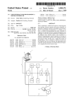
Please forgive us if we could not notify you timely towards any alteration to our product model No. or technical parameter. If the user's manual is not consistent with the actual operations due to technology upgrading, the explanation fight is reserved to Genway company. Indoor phone code
'----- Four·wlra ayalem
10 ,. -95 ,"
BIKk & Whlta
Camera
+Oescribe product name.
+Oescribe product model.
+Oescribe the trouble.
+ Leave yourTel No. and e-mail address.
Shel
I
Technical Operating currenl 200mA(DC 14V)
parameter Standby Clmant. 30mA(OC 14V)
Temperalure: -40r. .... 70 'C
Humldlty.
After-sale service consultation procedure
- - - - - Statement - - - - -
F5D10F[5
ID1lO-L~.;
F5DSO
functiorl"
F5S50
0, CalU Tal<! At:DIJSS oonIroI
F5S60
-
Operalklg voIIage: DC 14V
Color
1/3 CCO&CMOS
PAL sy.tam
VIsible angl.· 90 '
Light source:.
whtl8ltght LED
0pera\a'1g current. 700mA(DC 14V)
Technlcal SIandby wrnnt fOOmA(OC 14V)
.
parameter Temperatte.- l0 'C-55't'
H··...:....
0' --=
u....... ty. 1 ~ -"...
Mln . lllumlnatlOn~:.
0.1 Lux
----
Sa8en ~. 4 " CRTI5 ' TFT11 " 1FT
Re&clIution. ~> 450 Un&'320"234/480"234
...
>frn<
VER :l1
340302000860
~---------------------------------------------------------