1
ARM-JTAG-EW
User Manual
All boards produced by Olimex are ROHS compliant
Rev.B, March 2009
Copyright(c) 2009, OLIMEX Ltd, All rights reserved
1.
Introduction
ARM-JTAG-EW is a JTAG probe for debugging ARM microcontrollers. It's a
product by joined efforts of Olimex and IAR Systems, aiming not just to
release yet another fast USB JTAG compatible with Embedded Workbench,
but to make low cost JTAG with features available only in the expensive
logic analyzers. For this purpose ARM-JTAG-EW offers external
breakpoints in addition to ordinary software and hardware ones. User can
configure ARM-JTAG-EW to stop the target program on an external trigger,
defined by target power consumption, rising/falling edge of external
signals, analogue signal window value.
ARM-JTAG-EW emulates the IAR Systems' J-LINK API so it works like
normal J-LINK debugger, yet it adds some unique features which are
available only in the very high end and expensive debugger tools on the
market.
1.1.
Hardware Features
-
1.2.
JTAG connector with ARM 2x10 pin layout for target programming and
debugging
supports ARM targets working in voltage range 2.0–5.0V DC 1
USB full-speed connection to the PC
bi-color status LED
can provide 5.0V DC power to target via pin 19 of the JTAG connector
measurement of target current consumption
measurement of target MCU voltage and output voltage (pins 1 and 19
of the JTAG connector)
JTAG and SWD TCK frequency range 6kHz – 12MHz
SWO frequency range 1kHz – 3MHz
dimensions 50x40 mm (2x1.6") + 20 cm (8") JTAG cable
Software Features
-
DLL mostly compatible with original jlinkarm.dll from IAR-EW2
works with IAR Embedded Workbench 5.30 from IAR Systems
supports ARM7TDMI targets (e.g. SAM7, LPC2000, STR7)
supports Cortex M3 targets (e.g. STM32, LPC1000)
ability to put “external” breakpoints that trigger on a user-defined event
external event sources are the target MCU voltage, target supply voltage
and target consumption current
1 ARM-JTAG-EW outputs have 3.3V levels and will work with 5V targets that have TTL-level inputs.
2 DLL compatible means that we supply our own jlinkarm.dll. The original IAR-EW DLL will not work
with the ARM-JTAG-EW device because ARM-JTAG-EW and IAR J-Link use different USB
protocols.
1.3.
Electrostatic Warning
The ARM-JTAG-EW device is shipped in protective anti-static packaging.
The device must not be subject to high electrostatic potentials. General
practice for working with static sensitive devices should be applied when
working with this device.
1.4.
ARM-JTAG-EW Usage Requirements
Cables: 1.8 meter USB A-B cable.
Software: EW-ARM 5.30 from IAR Systems AB
2.
2.1.
Hardware
USB Connector
ARM-JTAG-EW has a standard USB device connector that requires a
standard USB A-B cable for connecting to a PC.
2.2.
JTAG Connector
The JTAG connector pin description is given below.
Pin Signal
№
Direc
tion3
1
I
UTG
Description
Target reference voltage. Target board must connect
3 Pin direction is from the side of ARM-JTAG-EW. I stands for Input (Target to ARM-JTAG-EW), and
O for output (ARM-JTAG-EW to Target).
Pin Signal
№
Direc
tion
Description
it to the MCU supply line that drives the JTAG pins.
Input has resistance 4 kΩ.
2.3.
2
UTG,2
I
3
nTRST
O
Target JTAG TAP reset. ARM-JTAG-EW has 100 Ω
(open resistor in series with this output. Driven as open
drain) drain output.
4
GND
-
Ground.
5
TDI
O
Target JTAG Data IN. ARM-JTAG-EW has 100 Ω
resistor in series with this output.
6
GND
-
Ground.
7
TMS/
O
SWDIO
Target JTAG Mode Select and Serial Wire Data
Input/Output. ARM-JTAG-EW has 100 Ω resistor in
series with this output.
8
GND
Ground.
9
TCK/
O
SWCLK
Target JTAG clock and Serial Wire Clock. ARMJTAG-EW has 100 Ω resistor in series with this
output.
10
GND
-
Ground.
11
RTCK
I
Target JTAG return clock. ARM-JTAG-EW has 100
Ω resistor in series with this input.
12
GND
-
Ground.
13
TDO/
SWO
I
Target JTAG data output and Serial Wire Output.
ARM-JTAG-EW has 100 Ω resistor in series with
this input.
14
GND
-
Ground.
15
nSRST
O
Target system reset. ARM-JTAG-EW has 100 Ω
(open resistor in series with this output. Driven as open
drain) drain output.
16
GND
-
Ground.
17
NC
-
Not connected in ARM-JTAG-EW.
18
GND
-
Ground.
19
UTGPWR
O
Target power supply voltage provided by ARM-JTAGEW. Supply is taken from USB and is switched by a
MOSFET transistor. There is 4 kΩ resistor
connected between this pin and ground.
20
GND
-
Ground.
-
Target board should connect it to the MCU supply
line that drives the JTAG pins.
Providing Target Power Via JTAG Connector
By default ARM-JTAG-EW connects the USB supply voltage to pin 19 of
the JTAG connector via MOSFET switch. Depending on the current
consumption and the used USB host and hubs the supplied voltage can
vary between 4.0V and 5.25V.
WARNING: In case of a target current consumption exceeding 400 mA,
including a short circuit on the target board, ARM-JTAG-EW will
shutdown its power output UTGPWR. Some USB hosts and hubs, however,
have faster short-circuit-detectors and will shutdown the power to ARMJTAG-EW before it has a chance to react.
Target power can be turned ON and OFF using the C-SPY macro
__jlinkExecCommand() like this:
//Turn power ON
execUserPreload() {
__jlinkExecCommand("SupplyPower = 1");
}
//Turn power OFF
execUserPreload() {
__jlinkExecCommand("SupplyPower = 0");
}
2.4.
LED Indication
ARM-JTAG-EW has a single dual color LED. Its states are shown below.
Slow blinking is with a period of 1s, and fast blinking is with a period of
128ms.
LED State
Description
OFF
ARM-JTAG-EW is not connected to USB, or it is
in USB suspended state.
Slow RED blinking
No target connected.
GREEN constantly on
Target connected.
Fast RED blinking
Target error caused by
overconsumption or MCU
bounds.
GREEN blinking
USB communication is taking place.
target
voltage
current
out of
Slow blinking sequence ARM-JTAG-EW is in boot loader mode.
GREEN→RED→OFF
3.
Software Installation
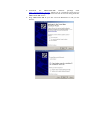
Please follow the following procedure exactly in the order it is written:
1. Install the Visual Studio 2008 SP1 Redistributable Package
vcredist_x86.exe
freely
available
from
Microsoft:
http://www.microsoft.com/downloads/details.aspx?
familyid=A5C84275-3B97-4AB7A40D-3802B2AF5FC2&displaylang=en
2. Install the .NET framework available freely from Microsoft: http://
msdn2.microsoft.com/en-us/netframework/default.aspx.
3. Download
the
ARM-JTAG-EW
software
package
from
http://www.olimex.com/dev. Extract it to a temporary directory on
your hard drive using the password found in the box along with the
ARM-JTAG-EW device.
4. Plug ARM-JTAG-EW in your PC and wait Windows to ask you for
drivers.
5. Next point the driver installation wizard to the “\driver”
subdirectory of the previously extracted software package.
6. If Windows complains that the driver is not signed then click to
continue and ignore the warning.
4.
Using ARM-JTAG-EW with IAR-EW 5.30 ARM
Using ARM-JTAG-EW under IAR-EW is straightforward. ARM-JTAG-EW
behaves just like IAR J-Link, provided that the original IAR-EW jlinkarm.dll
is replaced by ARM-JTAG-EW's one.
4.1.
Installing ARM-JTAG-EW DLL
Download
the
ARM-JTAG-EW
software
package
from
http://www.olimex.com/dev. Extract it to a temporary directory on your
hard drive using the password found in the box along with the ARM-JTAGEW device. The software package contains the file jlinkarm.dll. Find it and
copy it to the IAR-ARM “arm\bin” directory, like this:
C:\> copy c:\arm-jtag-ew-1.0.0.0\jlinkarm.dll "c:\Program Files\IAR
Systems\Embedded Workbench 5.20\ARM\bin"
Overwrite
c:\Program
Files\IAR
Systems\Embedded
Workbench
5.20\ARM\bin\jlinkarm.dll? (Yes/No/All): yes
1 file(s) copied.
5.
5.1.
External event breakpoints
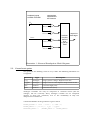
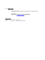
Overview
ARM-JTAG-EW has the ability to halt the target CPU upon detecting an
external event like a current/voltage spike/drop, external input trigger,
external input pulse detection.
External Breakpoints Block Diagram is given on page 9.
External events can be defined with a simple C-like expression like this
(see page 9 for more information):
(3000<U_tg && U_tg<3600)
So when ARM-JTAG-EW detects that UTG>3000mV AND UTG<3600mV, it
will shift a request to the target CPU to halt.
Multiple inputs can be mixed into one event:
(3000<U_tg && U_tg<3600) || I_tgpwr>200
WARNING: There is always some time between an actual event and the
corresponding action by ARM-JTAG-EW. Due to the limited sampling rate
of analogue signals, ARM-JTAG-EW cannot detect instantly changes on its
inputs. Also note that shifting the JTAG sequence for requesting a target
CPU halt also takes time, depending on the TCK frequency. Heavy USB
traffic can also influence the response time.
hardware inputs
to ARM-JTAG-EW
comparators
implemented
via firmware
UTG
UTG,threshold1
UTG,threshold2
boolean
function
defined
by a
Look-Up
Table
ITGPWR
ITGPWR,threshold1
request to
halt target
ITGPWR,threshold2
Illustration 1: External Breakpoints Block Diagram
5.2.
Formal event syntax
The grammar for defining events is very C-like. The following identifiers are
recognized:
Identifier
Type
Description
U_tg
analogue
Target power voltage. Expressed in mV.
I_tgpwr
analogue
Target current consumption. Expressed in mA.
true
boolean
Constant high (one)
false
boolean
Constant low (zero)
Analogue variables can only be compared to constant values (mV for
voltages, mA for currents). Every analogue variable can be compared
against at most two constants, due to the availability of only two
comparators in firmware.
A formal definition of the grammar is given below.
PRIMARY_BOOLEAN ::= 'true' | 'false' | ('(' EXPR ')')
PRIMARY_ANALOG ::= ['0'-'9']+ | 'U_tg' | 'I_tgpwr'
RELATIONAL_ANALOG ::=
(PRIMARY_ANALOG '<'
PRIMARY_ANALOG)
| (PRIMARY_ANALOG '<=' PRIMARY_ANALOG)
| (PRIMARY_ANALOG '>'
PRIMARY_ANALOG)
| (PRIMARY_ANALOG '>=' PRIMARY_ANALOG)
UNARY_EXPR ::= RELATIONAL_ANALOG | PRIMARY_BOOLEAN | ('!'+ PRIMARY_BOOLEAN)
EQUALITY_EXPR ::= UNARY_EXPR (('==' UNARY_EXPR) | ('!=' UNARY_EXPR))*
AND_EXPR ::= EQUALITY_EXPR ('&&' EQUALITY_EXPR)*
XOR_EXPR ::= AND_EXPR ('^^' AND_EXPR)*
OR_EXPR ::= XOR_EXPR ('||' XOR_EXPR)*
EXPR ::= OR_EXPR
5.3.
Setting events in IAR-EW and C-SPY
You will need to setup a C-SPY macro file. Please consult the IAR-EW
documentation for more information.
Use the __jlinkExecCommand() C-SPY macro with first argument “extbkpt”
to set an external event expression. For example, if you want to halt the
target if it consumes more than 100mA write the following in your C-SPY
macro file:
execUserPreload() {
__jlinkExecCommand("extbkpt I_tgpwr>100");
}
If you want to halt the target if its voltage goes out of the [3.0V – 3.6V]
range then you can write a macro like this:
execUserPreload() {
__jlinkExecCommand("extbkpt !(3000<U_tg && U_tg<3600)");
}
The vmeter command can be used to get the current state of the event
inputs:
__jlinkExecCommand("vmeter");
An example output of this command is:
Fri Feb 06 13:18:53 2009: J-Link Exec Command: VMETER: U_tg=3.254000
V, U_aux=0.000000 V, U_tgpwr=4.885000 V, I_tgpwr=17.000001 mA, D1=1,
target power enabled and OK
Fri Feb 06 13:18:53 2009: Error in C:\MyProject\test.mac at line 9, col 23:
Operation error.
Fri Feb 06 13:18:53 2009: Error while calling macro execUserPreload
NOTE: As seen above, IAR C-SPY reports an error when calling the vmeter
command. You can safely ignore it.
6.
Firmware Upgrade
In order to manually upgrade the ARM-JTAG-EW firmware do the
following:
1. Download
the
latest
software
package
from
http://www.olimex.com/dev
2. Connect ARM-JTAG-EW to your PC.
3. Disconnect ARM-JTAG-EW from any target boards.
4. Run the provided arm-jtag-ew-fwupd.exe application.
5. When prompted, please install the drivers for the bootloader.
7.
7.1.
Troubleshooting
The DLL file libusb0.dll cannot be loaded.
Please check that the driver for ARM-JTAG-EW is installed properly.
7.2.
The firmware upgrade application and/or the DLL cannot initialize properly.
Please check that you have installed the Visual Studio Redistributable
Package and the .NET framework, as described in the section Software
Installation.
7.3.
ARM-JTAG-EW cannot pull high/down the JTAG or reset lines
ARM-JTAG-EW has 100 Ω resistors in series with all its JTAG digital
inputs and outputs. If the target board has circuits for driving those
signals this will result in contention. Please remove all digital outputs,
LEDs, RS232 drivers, SPI, I2C from the JTAG and reset lines.
7.4.
Target cannot be initialized/reset/halted.
Ensure that you have selected the proper reset strategy. If target supports
RTCK enable it. If target supports Serial Wire then select it. Otherwise set
TCK to at least 1/6 of its CPU frequency. Don't forget that some targets
(like SAM7) start with 32kHz clock so you'll have to set TCK to 5kHz.
7.5.
SWO does not work and/or framing errors are reported
Ensure that you have selected the correct target CPU frequency in the
SWO setup menu.
7.6.
SWO capture overrun is reported
This might be caused by a USB congestion and/or slow PC host. Try
removing other USB devices from the hub where ARM-JTAG-EW is
connected. As a last resort select a lower SWO speed.
8.
Copyright Acknowledgments
The ARM-JTAG-EW software uses libusb-win32 available from
http://libusb-win32.sourceforge.net/. It is licensed under LGPL. The
Windows kernel driver is licensed under GPL.
9.
Electrical Characteristics
Symbol
Description
Condition
Min
UCC
ARM-JTAG-EW Power
Supply Voltage From
USB.
ICC
ARM-JTAG-EW Power
No target connected.
Supply Current
Consumption From USB.
UTG
Target Voltage.
ITGPWR,MAX
Maximum current that
can be drawn from target
via JTAG connector pin
19.
FTCK
Frequency on TCK JTAG/
SW pin.
5
FSWO
SWO capture speed.
1
Typ
4.0
Max
Uni
ts
5.5
V
40
2.0
mA
5.54
V
400
mA
12000 kHz
3000
kHz
4 ARM-JTAG-EW outputs have 3.3V levels and will work with 5V targets that have TTL-level inputs.
10.
Order Code
ARM-JTAG-EW – assembled and tested (no kit, no soldering required)
How to order?
You can order to us directly or by any of our distributors.
Check our web www.olimex.com/dev for more info.
Revision history:
REV.A
- February 2009 Initial release.
REV.B
- March 2009
Added notes about SWD/SWO.
Disclaimer:
© 2009 Olimex Ltd. All rights reserved. Olimex®, logo and combinations thereof, are registered trademarks of
Olimex Ltd. Other terms and product names may be trademarks of others.
The information in this document is provided in connection with Olimex products. No license, express or implied
or otherwise, to any intellectual property right is granted by this document or in connection with the sale of Olimex
products.
Neither the whole nor any part of the information contained in or the product described in this document may be
adapted or reproduced in any material from except with the prior written permission of the copyright holder.
The product described in this document is subject to continuous development and improvements. All particulars of
the product and its use contained in this document are given by OLIMEX in good faith. However all warranties
implied or expressed including but not limited to implied warranties of merchantability or fitness for purpose are
excluded.
This document is intended only to assist the reader in the use of the product. OLIMEX Ltd. shall not be liable for
any loss or damage arising from the use of any information in this document or any error or omission in such
information or any incorrect use of the product.
Mouser Electronics
Authorized Distributor
Click to View Pricing, Inventory, Delivery & Lifecycle Information:
Olimex Ltd.:
ARM-JTAG-EW