1
US005237652A
United States Patent [191
[11] Patent Number:
McManus
[45]
[54] PROGRAMMING SYSTEM FOR
PROGRAMMABLE LOGIC CONTROLLER
[76] Inventor:
Kirby L. McManus, 15216 NE. 110th
Pl., Redmond, Wash. 98052
Date of Patent: '
5,237,652
Aug. 17, 1993
Bulletin No. 1745, Allen-Bradley Company, Industrial
Control Group, vol. 2.5, Jan. 1987, 19 pages.
“User’s Manual” for 6200 Series Software, PLC-2 Pro
gramming Software, Allen-Bradley, Co. Inc., 1988.
[21] Appl. v No.: 620,640
Bryan, E. A. and Bryan, L. A., “Programmable Con
trollers: Theory and Implementation,” promotion bro
[22] Filed:
chure for the text, Industrial Text Co.
Nov. 30, 1990
[51]
[52]
[58]
Int. Cl.5 ......................... .. G05B 9/02; G06F 3/00
US. Cl. ............................ .. 395/155; 364/ 147
Field of Search ................ .. 364/DIG. l, DIG. 2,
[56]
364/147; 395/500, 162, 140, 155
References Cited
4,038,562
7/1977
Kintner ............................. .. 307/203
4,326,207
4/1982
Suda et
4,608,628 8/1986
4,703,414 10/1987
Saito et al.
Inoue et al.
4,792,918 12/1988
Hirase et a1. .... ..
. . . . ..
2/1991
5,062,052 10/1991
Zifferer et al.
364/900
.... .. 364/141
.... .. 364/147
. 364/900
4,845,627 7/1989 Nadolski et al
4,991,076
364/468
.. 364/147
Sparer et al. ...................... .. 364/473
FOREIGN PATENT DOCUMENTS
.
Signal Controls Co., Jan. 1987, 12 pages.
“The GE Series One Programmable Controller,” Gen
eral Electric Co. product brochure, Apr. 1986, 4 pages.
“The GE Series Three Programmable Controller,”
General Electric Co. product brochure, Apr. 1986, 4
pages.
U.S. PATENT DOCUMENTS
. .. .
“Programmable Controller,” Bulletin No. 943, Eagle
“Modicon 984 Family Control Products,” System prod
uct description, Modicon, Inc., Jan. 1990, 11 pages, plus
Fact Sheet, 5 pages.
Primary Examiner-Robert L. Richardson
Attorney, Agent, or Firm-Christensen, O’Connor,
Johnson & Kindness
[57]
ABSTRACT
971252
7/1975
Canada ................................ .. 342/21
A system for creating a program for a programmable
985396
3/ 1976
Canada .............................. .. 340/162
logic controller (PLC). The user inputs a ladder logic
command in an alphanumeric format, and the system
creates a corresponding ladder logic graph on a display
means. The user may then verify the relationship de
' 3808135 9/1989 Fed. Rep.
89/06010 6/1989 PCT Int’l
89/09961 10/1989 PCT 1m
89/09976 10/1989 PCT 1m
2099667 3/1981
2112974 11/1981
of Germany
.. 1/00
Appl. ..... ..
9/06
Appl. ..................... .. 7/00
Appl. ................... .. 15/60
United Kingdom .................. .. 3/153
United Kingdom .................. .. 11/32
picted in the graph, before forwarding the ladder logic
command to the PLC.
_ OTHER PUBLICATIONS
“SLC 150 Programmable Controler,” Product data
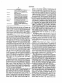
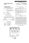
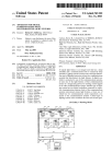
80?
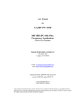
INPU T/EDI T
12 Claims, 6 Drawing Sheets
(82
'—————> LOAD PROGRAM
PLC PROGRAM ¢_> SAVE PROGRAM n84
86—\
SELECT LADDER
LOGIC COMMAND(S)
DISPLAY CORRESPONDING
LADDER LOGIC GRAPH(S')
1 r“ 9O
DOWNLOAD
PROGRAM
TO PLC
US. Patent
Aug. 17, 1993
Sheet 1 of 6
12
5,237,652
_—*>
M
PROGRAMMABLE
>
LOGIC
___o 14
CONTROLLER
'
a’) j
20*” MICROPROCESSOR ____o
22 ‘f4 MEMORY
'—*>
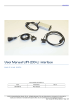
FIG. 1.
44
A
40
x30
B
C
Vll
W—( >
32/‘ 343 42 ‘K36
FIGZQ
.A;
I
I
7 :3:
50
v
52
C
D
US. ‘Patent
Aug. 17,1993
Sheet 2 of6
COMPUTER
I
5,237,652
J60
_
70
Q
62 /~\_ DISPLAY
'?—+PLc
72
64/_ \ DEVICE
INPUT
66 "\_ MEMORY
8 O \2
(‘82
INPUT/EDIT '_-—+ LOAD PROGRAM
PLC PROGRAM ‘-_-___> SAVE PROGRAM r84
l / 90
86\
SELECT LADDER
DOWNLOAD
LOGIC COMMAND(S)
PROGRAM
TO PLC
Y
DISPLAY CORRESPONDING
LADDER LOGIC GRAPH(S)
F186.
US. Patent
Aug. 17, 1993
Sheet 3 of 6
5,237,652
110
108
SwTe'm
.
AtTem
L, i J’
K
772 Warmin
, Dg
"\104
my‘
i ‘L 106
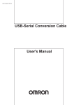
FI G . 6 a.
.S'wTz'me TimeZero
j] -%
1'\|L
136
TimerRun'mlng
wC D
122
C
E TimerRunnmg
: #
132$ Warming 2
1'
1
l
J34
D00?"
*1‘
124
H
Start
MicroWa'ues
HL)
K
K
g
126
128
130
Warming TimerRunning
?'mL
:\k—
_
Door
{\IL
F[G.60l.
MicroWowes
{RD
US. Patent
Aug. 17, 1993
Sheet 4 of 6
5,237,652
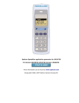
(DISPLA Y FUNCT! 0N)
INITIALIZA TION
200 \/ DRAW ENTRY POINT
202p
91
GET NEXT TOKEN
Z04
EXAMINE
PUNCTUA TION
TOKEN
VARIABLE NAME
208» DRAW fYMBOL
210»
YES
RESET FLAGS
MORE
TOKENS
?
206
K PROCESS
PUNCTUATION
US. Patent
Aug. 17, 1993
Sheet 5 of 6
PROCESS
,
PUNCTUATION
’
-
%
F]
8.
220
YES
N0
5,237,652
YES
LOGIC
= 9E
‘2mm
N0
N222
YES
f224
MOVE DOWN --_-->
N0
‘
N226
YES
@
A
SET LOOIO
=
No
9
~»
N228
YES
SET (E3010
MOVE- POINTER
N0
@
YES
SET SENSE
N230
FLAG
—_‘—_—’
N0
gé
YES RESET FLAGS
9
YES DRAW OUTPUT
SYMBOL
N232
T0 DEFA UL TS —__—*_
N234
N0
@513
US. Patent
Aug. 17, 1993
Sheet 6 of 6
5,237,652
256
254
B ‘K
A
\——1C l_
—1
——1l——-»—
258
250/‘ E52 \260 - 262 /264
r17
266))
FIG. 9.
A
i‘
B
i
.i
C
E
10.50
A
280
T)v
_K282
284
1
5,237,652
PROGRAMMING SYSTEM FOR
PROGRAMMABLE LOGIC CONTROLLER
FIELD OF THE INVENTION
be regarded as normally open (i.e., off) switches, and
the ladder logic graph can be interpreted by noting that
The present invention relates to programmable logic
controllers, also known as programmable controllers,
and in particular to techniques for creating programs
for such controllers.
a voltage or other signal present on line segment 44 to
the left of the input symbols will reach output point C if
and only if switches A and B are both closed (i.e., on).
FIG. 3 represents a second ladder logic graph with
inputs A, B, and output C, except that now inputs A and
BACKGROUND OF THE INVENTION
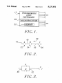
Programmable logic controllers (PLCs) are special
ized data processors that are in widespread use in a
variety of ?elds, for example as controllers for machine
tools, material handling and assembling systems, for
molding and casting machines, and for robotics systems.
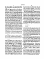
FIG. 1 presents a simpli?ed diagram of a PLC 12 that
includes a plurality of input terminals 14, a plurality of
output terminals 16, microprocessor 20, and memory
2
and B are ANDed together is indicated by the fact that
their input symbols are connected in series by line seg
ment 40. Line segment 42 indicates that the result of A
AND B controls output C. Input symbols A and B can
15
B are connected in parallel by line segments 50 and 52.
This ladder logic graph is equivalent to the statement ‘
that output C will be on if either input A or input B is
on. Thus, the parallel connection provided by line seg
ments 50 and 52 indicates the logical operation OR. As
with FIG. 2, the graph of FIG. 3 can be interpreted by
noting that a signal present on line segment 50 will
reach output Cif either switch A or switch B is closed.
20
In general, two prior methods have been used to
22. Input terminals 14 and output terminals 16 are col
lectively referred to as IO points.
permit a user to create ladder logic programs for PLCs.
PLC 12 operates under the control of a program
In a ?rst method, the PLC includes an input module
stored in memory 22. When incorporated into an appli
that includes a small keyboard. The keyboard typically
cation, each input terminal 14 will be connected to a
includes numeric keys, function keys, and a small num
switch, a relay contact, or some other device capable of 25 ber of other keys representing different types of vari
providing an electrical signal indicating one of two
ables. The program is entered directly into memory 22
states, such as open vs. closed in the case of a switch or
via such a keyboard. For example, to enter the ladder
relay contact, or high vs. low in the case of a voltage
logic statement corresponding to FIG. 3, a user might
signal. Each output terminal 16 is connected to a device
such as a status indicator, a relay coil, etc., that is to be 30 enter an identi?er for input variable A, then press a
controlled by the PLC.
The PLC operates by repetitively executing what is
termed a scan. During each scan, the PLC reads the
function key specifying a logical 0R operation, then
enter a symbol for input variable B, and ?nally a symbol
for output variable C.
signals present at input terminals 14, to determine what
A second prior technique for programming PLCs
PLC to control its operation is typically expressed in
what is termed "ladder logic” format. Each ladder logic
PC software converts the graph into the corresponding
ladder logic command. The ladder logic commands are
program comprises one or more ladder logic state
then transferred to the PLC and stored in memory 22.
will here be referred to as input data. Next, the PLC 35 involves creating the ladder logic program on a sepa
rate device, such a personal computer, and then trans
combines the input data with the program stored in
ferring the program to memory 22 via a serial data link
memory 22 to determine the corresponding output data.
or the like. In such systems, the operator of personal
Finally, the PLC uses the output data to set the values
computer draws a ladder logic graph directly on the
of the signals at output terminals 16, and then proceeds
to start the next scan.
40 computer display screen, one graphical element at a
time. When a given ladder logic graph is completed, the
The program stored in memory 22 and used by the
ments. In the PLC art, these ladder logic statements are 45
often termed “rungs". Each ladder logic statement de
?nes the relationship between an output variable and, in
most cases, one or more input variables. Input variables
SUMMARY OF THE INVENTION
The present invention provides a system for creating
a program for a programmable logic controller (PLC).
include variables corresponding to the signals at input
terminals 14, while output variables include variables
corresponding to the signals at output terminals 16.
Other types of input and output variables are described
below. A simple ladder logic statement might indicate
that a particular output variable is “on” if and only if
creates a corresponding ladder logic graph on a suitable
display means. The user can then verify the relationship
segments 40 and 42. Input symbols 32 and 34 are as
signed labels or variable names A and B respectively,
while variable name C is assigned to output symbol 36.
logic commands. Each command includes an output
Using the invention, a user inputs a ladder logic com
mand in an alphanumeric format, and the system then
between input and output variables depicted in the
graph, and if necessary edit the alphanumeric command
input variables 1_ and 2 are both “on”.
‘
55 until the graph depicts the desired relationship. Thus
For easier comprehension, ladder logic statements
both program entry and program veri?cation take place
and programs are often expressed in terms of ladder
in the most convenient respective formats, i.e., alphanu
logic graphs. A simple ladder logic graph 30 is shown in
meric for program entry and graphical for program
veri?cation.
FIG. 2. The ladder logic graph comprises input symbols
32 and 34, and output symbol 36, interconnected by line
In a preferred embodiment, the system creates a pro
In the convention used in ladder logic graphs, the graph
gram comprising one or more alphanumeric ladder
variable, and logic speci?cations indicating the manner
in which the output variable is to be determined. The
of FIG. 2 is equivalent to the statement that output C is 65 system comprises means for accepting user input data
“on” if and only if inputs A and B are both “on”, i.e., the
specifying one or more ladder logic commands in an
equivalent of a logical AND operation between inputs
alphanumeric format, and means for converting one or
A and B to produce output C. The fact that inputs A
more selected ladder logic commands into a corre
3
5,237,652
4
sponding ladder logic graph. The ladder logic graphs
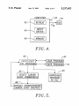
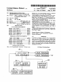
input/edit module 80, from which point the user may
are displayed, and permit veri?cation of the ladder logic
commands. The display is preferably via a computer
display screen, although other display means, such as
save the PLC program, select other ladder logic com
mands, or download the PLC program to PLC 70 via
download function 90.
In order to provide a clear understanding of the oper
ation of the present invention, a preferred embodiment
of display function 88 will now be described, in connec
printers, may also be used.
Each ladder logic graph includes an output symbol
corresponding-to the output variable, and one or more
connection symbols that graphically indicate the logic
speci?cations of the selected command. Typically, each
ladder logic command also includes one or more input
variables, and each ladder logic graph includes an input
symbol corresponding to each input variable. In a pre
ferred embodiment, the connection symbols include
line-like elements that connect a pair of input symbols in
tion with a speci?c PLC program. The PLC program
used for an example will be a program for controlling
the operation of a conventional microwave oven. The
statements comprising the program are as follows:
1 @Start=l
2 @Door=2
series to indicate a logical AND operation, and that 15
connect a pair of input symbols in parallel to indicate a
4 @SwTemp=4
5 @TimeZero=5
logical OR operation.
FIGS. 2 and 3 show examples of ladder logic graphs;
6
7
8
9
l0
ll
FIG. 4 is a block diagram illustrating the use of a
12 <TimerRunning,Warming.Door.Start>MicroWaves L
BRIEF DESCRIPTION OF THE DRAWINGS
FIG. 1 is a simpli?ed diagram of a programmable 20
logic controller;
@AtTemp=0
@Microwaves=7
@Warming=ll9
@TimerRunning=ll8
<SwTemp. AtTemp>Warming
(SwTime. TimeZero>Timer Running
13 < Warming. TimerRunning, Door>MieroWaves R
separate computer to produce the PLC program;
FIG. 5 is a block diagram of a preferred embodiment 25
The numbers in the left hand column above are line
of the programming system of the invention;
reference numbers inserted for the purpose of the pres
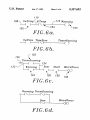
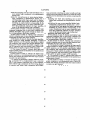
FIGS. 6a-6d illustrate ladder logic graphs corre
sponding to a particular PLC program;
ent description, and do not form part of the PLC pro
gram itself.
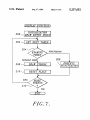
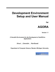
FIG. 7 is a ?ow chart showing the overall operation
of a preferred embodiment of the invention;
In a typical PLC, each IO point is identi?ed by a
30
FIG. 8 is a ?ow chart of the punctuation processing
unique number, and such numbers could be used in the
program created by computer 60. However, to make
module;
FIG. 9 illustrates a ladder logic graph derived from a
the PLC programs more readily comprehensible, a
ladder logic command using parentheses; and
preferred embodiment of the present invention provides
FIG. 10 is a ladder logic graph that includes a timer 35 a method for associating an alphanumeric label with
symbol.
DETAILED DESCRIPTION OF THE
PREFERRED EMBODIMENT
each IO point number. In the example set forth above,
lines 1-9 are examples of labeling commands that pro
vide such labels, all labeling commands beginning with
the symbol “@”. Thus for example in line 1 above, the
alphanumeric label “Start” is associated with 10 point
The programming system of the present invention is 40
outlined in FIGS. 4 and 5. Referring initially to FIG. 4,
1.
the PLC program is initially created on computer 60
The symbol “<” indicates a ladder logic command.
that includes display (e.g., CRT monitor) 62, input sys
Thus in the program listed above, lines 10-13 are the
tem (e.g., keyboard) 64, and memory 66. An operator
ladder logic commands. Within each ladder logic com
uses computer 60 to create a suitable PLC program, 45 mand, a period represents a logical AND operation, a
optionally stores the program in memory 66, and then
comma represents a logical OR operation, a backslash
downloads the program to PLC 70 via link 72 that may
represents a logical NOT operation, and the “>” sym
comprise a standard RS-232 serial line.
bol indicates that the following symbol is the output of
FIG. 5 outlines a preferred embodiment of a program
that command. Thus, for example, line 10 states that
for controlling computer 60 in accordance with the 50 when input variable SwTemp is true AND input vari
present invention. The program comprises input/edit
able AtTemp is not true, then output variable Warming
module 80 that may essentially comprise a text editor or
the like. The input/edit module permits a user to input
is true.
a new PLC program, or to edit a preexisting PLC pro
It will be assumed that the input and output variables
shown in the above-listed program have the following
gram, in an alphanumeric format. A preexisting pro 55
meanings:
gram to be edited may be loaded from memory 66 via
load function 82, and a new or edited program may be
saved in memory 66 by save function 84.
During the input or editing process, the user may
Start
select one (or more) of the ladder logic commands via
select function 86. When a given ladder logic command
is selected, display function 88 determines and displays
the corresponding ladder logic graph on display 62.
This display function is described in detail below. Dis
play function 88 essentially allows the user to visualize 65
each ladder logic command, so that the program input
and editing process becomes more intuitive and reliable.
Exiting from display function 88 returns the user to
This input has the value true when an
operator presses the start switch of the
microwave oven, and has the value false
whenever the start switch is not being
pressed.
Door
This input has the value true when the
SwTime
door of the microwave oven is closed, and
has the value false when the door is open
This input has the value true when the
microwave oven is in timer mode, and the
value false when the oven is in
temperature mode. Timer mode implies
that the oven will be on for a specified
length of time, while temperature mode
5
5,237,652
indicates that the oven will remain on
SwTemp
TimeZero
AtTemp
Microwaves
Warming
TimerRunning
until a predetermined temperature is
reached
This input is true in temperature mode,
tively, indicating a logical OR operation. Line segment
132 includes segment 136 that indicates the beginning of
a ladder logic graph. The symbol “L” in output symbol
130 re?ects the latch indicator “L” appearing at the end
of program line 12. The latch indicator speci?es that the
Microwaves output will be latched into the true state by
false in timer mode
This input has the value true when the
mechanical timer has counted down to
zero, and otherwise has the value false
This input has the value true when the
temperature has reached a preselected
level, and otherwise has the value false
l0 the PLC whenever the conditions shown in FIG. 60 are
The oven is on when this output is true,
satis?ed. Thus an operator of the microwave oven is
and off when this output is false
As described below, this internal variable
represents an "intemal relay" that is not
associated with any IO point. Its
signi?cance is further described below
This internal variable represents a second
internal relay
6
spond to the internal variables TimerRunning and
Warming, respectively. These input symbols are con
nected in parallel by line segments 132 and 134, respec
-continued
only required to momentarily depress the Start switch
15
in order to turn the oven on. In a preferred embodiment
of the invention, each output variable can have one of
four modes. These modes are normal (N), one-shot (O),
toggle (T), and latch (L). The N mode is the default,
and causes the output variable to be on when its input is
on, and off when its input is off. Latch mode causes the
In the present system, the fact that the Warming and
output variable to remain on even after its input is off.
Timer Running are internal variables is indicated by the 20 For an output variable that has been latched, the vari
numbers of the IO points (119 and 118) associated with
these variables. An internal variable can be both an
able is turned off using the R symbol. Finally, one-shot
mode indicates that when its input is on, the output
input variable and an output variable. For example, in
variable remains on for one complete scan, and then is
line 10, internal variable Warming is an output variable,
while in lines 12 and 13, internal variable Warming is an 25 turned off.
As indicated in FIG. 6a‘, the microwave output will
input variable.
be reset (R) whenever the door is open, or whenever
Line 10 of the PLC program set forth above states
the oven reaches the preset temperature in temperature
that when input SwTemp is true AND input AtTemp is
mode or the end of a preset interval in timer mode.
false, then internal variable Warming is true. When this
ladder logic command is selected in block 86 of FIG. 5, 30 Comparing program lines 1043 with FIGS. 6a~6d
readily indicates the improvement in program writing
display function 88 determines and produces the ladder
and debugging that is made possible by the present
logic graph shown in FIG. 6a, in which the ladder logic
invention.
command has been translated into an equivalent ladder
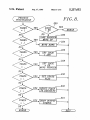
FIGS. 7 and 8 set forth a ?ow chart for a preferred
logic graph. The ladder logic graph comprises input
symbols 102 and 104, output symbol 106, and line seg 35 embodiment of the display function. The operation of
these flow charts will be illustrated by program line 12
ments 108, 110, and 112. Each input symbol comprises a
above, and the corresponding ladder logic graph shown
pair of spaced vertical bars, the name of the correspond
in FIG. 6c. The display function of FIG. 7 begins with
ing input variable above the bars, and the horizontal
an initialization step in block 200. Preferably, the dis
lines to either side of the vertical bars. Output symbol
106 is similar, except that it includes parentheses rather 40 play area on which the ladder logic graph will be drawn
than vertical bars. Input symbol 104 includes a back
is divided into a two-dimensional array of grid elements,
slash that re?ects the logical NOT symbol appearing
with each grid element being large enough to display an
input or output symbol. On a conventional 80X 25 com
with this in front of the AtTemp variable in program
line 10. Line segment 108 simply indicates the beginning
puter monitor, a suitable size for each grid element is
of the ladder logic graph, line segment 110 indicates a 45 eight characters wide and two characters high.
logical AND operation corresponding to the period in
Block 200 initializes a current grid pointer, preferably
program line 10, and line segment 112 connects the
to a grid element at the left center of the drawing area.
input symbols and their associated logic with output
Block 200 then proceeds to draw the entry point for the
symbol 106.
ladder logic graph, the entry point being shown by
For many if not most PLC programmers, the graphi 50 reference number 136 in FIG. 6c. Each time that a given
cal display shown in FIG. 6a can be more readily com
graph element is drawn, the grid pointer is updated in a
prehended than the textual command shown in program
corresponding manner. Thus, in the case of entry point
line 10 above. However, the programming system of the
136, the grid pointer would be incremented to specify
present invention does not require the user to painstak
that the next portion of the ladder logic graph will be in
ingly create a ladder logic graph on the computer 55 the middle row, second column, of the grid array.
screen. Instead, the invention requires the user to per
The program diagrammed in FIG. 7 then proceeds in
form the far simpler task of typing in an alphanumeric
block 202 to obtain the next token from the alphanu
command, and the corresponding ladder logic graph
meric ladder logic command. A “token" is a unit of the
may then be created automatically.
ladder logic command. Thus for program line 12, the
In a similar manner, FIGS. 6b, 6c, and 6d illustrate the 60 tokens are the variable names TimerRunning, Warming,
ladder logic graphs created by display function 88 for
PLC program lines 11-13, respectively. FIG. 6b illus
trates the setting of the internal variable TimerRunning.
Door, Start, and Microwaves, and the punctuation sym
bols< , comma, period, backslash, and>. Block 204
examines the next token, to determine whether it is a
FIG. 6c shows how the microwave oven is turned on,
variable name or a punctuation symbol. In program line
while FIG. 6d shows how the microwave oven is 65 12,-the ?rst token is the punctuation symbol<, so that
turned off. Examining FIG. 6c in detail, this ladder logic
program control ?ows to block 206 that is further dia
graph includes input symbols 122, 124, 126, and 128, and
grammed in FIG. 8. For the token “<”, block 232 will
output symbol 130. Input symbols 122 and 124 corre
cause all flags to be reset to their default values, since
7
5,237,652
this token corresponds to the beginning of a program
line. Control will then return to block 212 in FIG. 7,
and from there back to block 202 to retrieve the next
token.
The next token is the variable name TimerRunning,
so that block 204 passes control to block 208, which
draws the corresponding input symbol 122 shown in
FIG. 6c. Block 210 then resets all ?ags, and control
again returns to block 202 to retrieve the next token.
Since the next token is a “,”, the result will be that block
288 (FIG. 8) will set the logic ?ag equal to OR. The
succeeding token, the variable name Warming, will
8
grid pointer back to point 252. The next token is the
input name C, and input symbol 260 is then drawn, after
which the program encounters the right parentheses
token. This causes the grid pointer to move down in
block 224, drawing line segment 262. The process then
continues as previously described with the production
of line 264 and output symbol 266.
Most PLCs include means for emulating commonly
used electronic hardware elements such as counters and
timers. Each timer or counter has an associated variable
that controls its operation. Such variables will herein be
referred to as timer 10 points and counter IO points,
flag is set, block 208 moves the grid pointer down one
respectively. A timer counts up or down from a preset
row, and then draws input symbol 124. The next token 15 value for as long as its associated timer 10 point is on.
“.” resets the logic ?ag to AND in block 226, so that the
Counters, on the other hand, will count one count
next token “Door” causes block 208 to be entered with
whenever the associated counter IO point makes a tran
cause control to be passed to block 208. Since the OR
the logic flag equal to AND. As a result, input symbol
126 and line segment 134 are drawn to the right of the
sition from off to on. The output of a timer or counter
can be in normal, one-shot, toggle or latch mode, as
prior symbol 124, without changing rows. A similar 20 with a conventional output variable.
process occurs for input symbol 128. The token “>”
In a preferred embodiment, the programming system
then results in the drawing of output symbol 130 and the
of
the present invention uses a two-step process to cre
line interconnecting this output symbol with input sym
ate a ladder logic graph that includes a counter or timer.
bol 128 at which point the display function is complete.
FIG. 8 also illustrates the way in which the display 25 For example, the following two statements added to a
PLC program
function uses parentheses, which may be used in the
ladder logic commands to group operations. As indi
cated by blocks 220, 222, and 224, the “(” token causes
>tm0 10.50 2 T A
the current grid pointer to move up by one row, assum
ing that the OR logic ?ag has not been set. The token 30
“)” causes the grid pointer to move back down one row.
FIG. 8 also illustrates that in block 230, the backslash
token causes a sense ?ag to be set, which flag is used by
would produce the ladder logic graph shown in FIG.
10. The ?rst statement set forth above, beginning with a
right hand angle bracket, is a definition of a particular
timer, here labeled tmO. The four parameters following
symbol.
.
35
the timer name provide the preset value (the value set
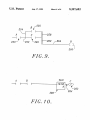
In a preferred embodiment, the present invention
provides for the use of parentheses to specify the order
into the timer or counter when the timer is reset), the
in which logical operations are to be carried out. For
name of the output variable (C) controlled by the timer
example, a ladder logic statement of the following form
and the output mode (N ,O,T or L). The fourth parame
ter “A” is an optional parameter. When included, it will
draw symbol block 208 to place a backslash in the input
would normally be evaluated by ANDing variables a
and b, and then ORing the result with variable c to
cause the timer or counter to be automatically reset'
when the count hits zero.
FIG. 10 illustrates the ladder logic graph correspond
ing to the second program statement set forth above. As
produce variable d. However, the sequence of opera
shown,
the timer symbol tmO produces the display of a
45
tions can be modi?ed using parentheses as follows
timer symbol 280 that includes a rectangle with the
timer label tmO above the rectangle, the preset and auto
parameters within the rectangle, and the output variable
In this case, variables b and c are ORed, and the result
C to the right of the timer symbol connected to it by line
is then ANDed with variable a to produce variable d. 50 segment 282. A similar display would be created for a
In a preferred embodiment of the present invention,
counter.
this above statement (with parenthesis) would produce
While the preferred embodiments of the invention
the ladder logic graph shown in FIG. 9. Referring to
have been illustrated and described, variations will be
the ?ow chart of FIGS. 7 and 8, the entry point symbol
apparent to those skilled in the art. Accordingly, the
would be drawn in block 200, and input symbol 250 is 55 scope of the invention is to be determined by reference
then drawn in block 208. In this graph, the entry point
to the following claims.
symbol merges with the horizontal line at the left of the
The embodiments of the invention in which an exclu
input symbol. The following token is a period, and
sive property or privilege is claimed are de?ned as
block 226 therefore sets the logic flag equal to AND.
The next token is a left parentheses, so the control is 60 follows:
1. A system for generating a display useful for creat
then passed to block 220 that tests the logic ?ag. Since
ing
a program for a programmable logic controller
the logic ?ag is not equal to OR, block 222 causes the
(PLC), the program comprising one or more alphanu
current grid pointer position 252 to be saved, and then
meric ladder logic commands, the PLC being adapted
moves the grid pointer up one grid element, drawing
line 254. The next token, the variable name B, results in 65 to execute said ladder logic commands, each ladder
logic command comprising an output variable and logic
the drawing of input symbol 256. The next token is a
comma, and block 228 therefore sets the logic ?ag equal
speci?cations indicating the manner in which the output
to OR, draws line segment 258, and moves the current
variable is to be determined, the system comprising:
‘5,237,652
means for accepting user input data specifying one or
more ladder logic commands in an alphanumeric
10
logic command comprising an output variable and logic
speci?cations indicating the manner in which the output
format; and
variable is to be determined, the method comprising the
steps of:
means for converting one or more selected ladder
logic commands in alphanumeric format into a 5
corresponding ladder logic graph and for display
ing said ladder logic graph, the ladder logic graph
including an output symbol corresponding to the
accepting user input data specifying one or more
ladder logic commands in analphanumeric format;
and
converting the one or more speci?ed ladder logic
output variable, and one or more connection sym
bols that graphically indicate the logic speci?ca 10
tions of the selected ladder logic command.
2. The system of claim 1, wherein each ladder logic
commands in alphanumeric format into a corre
sponding ladder logic graph, the ladder logic graph
including an output symbol corresponding to the
output variable and one or more connection sym
command comprises one or more input variables, and
wherein the ladder logic graph includes an input sym
bol corresponding to each input variable.
15
3. The system of claim 2, wherein each connection
symbol comprises one or more line-like elements inter
bols that graphically indicate the logic speci?ca
tions of the selected ladder logic format; and
displaying said ladder logic graph.
8. The method of claim 7, wherein each ladder logic
command comprises one or more input variables, and
connecting the input and output symbols.
wherein the ladder logic graph includes an input sym
4. The system of claim 3, wherein the logic speci?ca
bol corresponding to each’ input variable.
tions include an AND speci?er specifying a logical 20 9. The method of claim 8, wherein each connection
AND operation, an OR speci?er specifying a logical
symbol comprises one or more line-like elements inter
OR ‘condition, and wherein the line-like elements con
connecting the input and output symbols.
nect a pair of input symbols in parallel to signify a logi
10. The method of claim 9, wherein the logic speci?
cal OR operation, and interconnect a pair of input sym
cations include an AND speci?er specifying a logical
bols in series to signify a logical AND operation.
25 AND operation, an OR speci?er specifying a logical
5. The system of claim 1, wherein each input and
OR condition, and wherein the line-like elements con
output symbol includes an identi?er for the symbol in an
nect a pair of input symbols in parallel to signify a logi
alphanumeric format.
I
cal OR operation, and interconnect a pair of input sym
6. The system of claim 1, wherein the ladder logic
bols in series to signify a logical AND operation.
graph comprises a two-dimensional array of grid ele 30 11. The method of claim 7, wherein each input and
ments, and wherein each input and each output symbol
output symbol includes an identi?er for the symbol in an
occupies one grid element.
alphanumeric format.
7. A method of generating a display useful for creat
12. The method of claim 7, wherein the ladder logic
ing a program for a programmable logic controller
graph comprises a two-dimensional array of grid ele
(PLC), the program comprising one or more alphanu 35 ments, and wherein each input and each output symbol
meric ladder logic commands, the PLC being adapted
occupies one grid element.
$
'
i
t
i
to execute said ladder logic commands, each ladder
45
50
55
65