1
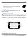
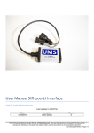
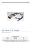
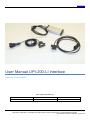
www.ums.sg
User Manual UPI-200-LI interface
Used for Linde forklifts
(Last update (2013/06/17))
Date
Description
2013/06/16
First release
Rev.nr
© 2013 Universal Machine Solution Pte Ltd. All Rights Reserved. This user manual (one or more parts of it) may only be
reproduced, distributed or translated with explicit written and prior permission by Universal Machine Solution.
User manual UPI-200-LI Interface - Page 1/28
www.ums.sg
Table of Contents
1
Introduction .................................................................................................................................................................3
1.1
Use .................................................................................................................................................................... 3
1.2
Warnings ........................................................................................................................................................... 3
1.3
Contents and first use ....................................................................................................................................... 3
2
Supported machines ..................................................................................................................................................4
3
Locating the service connector on the truck ..............................................................................................................6
3.1
Trucks with CANbus .......................................................................................................................................... 6
3.2
Trucks with OBD ............................................................................................................................................... 6
4
Starting up the UPC-100 handset ..............................................................................................................................6
5
Structure of the menu .................................................................................................................................................6
5.1
CANbus ............................................................................................................................................................. 6
5.1.1
Measurement (Zone D) ............................................................................................................................. 6
5.1.2
Setup (Zone E) .......................................................................................................................................... 7
5.1.3
Calibration (Zone F) .................................................................................................................................. 7
5.1.4
Logbook (Zone G) ..................................................................................................................................... 7
5.1.5
Console (Zone I) ........................................................................................................................................ 7
5.2
OBD ................................................................................................................................................................... 7
5.2.1
Terminal (Zone D) ..................................................................................................................................... 7
5.2.2
Reset service hours (Zone E) ................................................................................................................... 7
5.2.3
Console (Zone I) ........................................................................................................................................ 7
6
Cleaning the device ....................................................................................................................................................7
7
Maintenance ...............................................................................................................................................................7
8
Storage .......................................................................................................................................................................7
9
Problem solving ..........................................................................................................................................................8
10
Transport ....................................................................................................................................................................8
11
Regulatory compliance ...............................................................................................................................................8
12
Warranty .....................................................................................................................................................................8
13
Addendum ..................................................................................................................................................................9
13.1
Tilt angle sensor calibration procedure for Linde BR391 trucks ....................................................................... 9
13.2
Tilt angle sensor calibration procedure for Linde BR392 trucks ..................................................................... 13
13.3
Tilt angle sensor calibration procedure for Linde BR393 trucks ..................................................................... 18
13.4
Tilt angle sensor calibration procedure for Linde BR394 trucks ..................................................................... 23
13.5
Tiller foot poti setup for Linde BR1152 trucks ................................................................................................. 27
13.6
Speed reduction according to position of handlebar (tiller) for Linde BR1190 trucks ..................................... 28
© 2013 Universal Machine Solution Pte Ltd. All Rights Reserved. This user manual (one or more parts of it) may only be
reproduced, distributed or translated with explicit written and prior permission by Universal Machine Solution.
User manual UPI-200-LI Interface - Page 2/28
www.ums.sg
1 Introduction
1.1 Use
The UPI-200-LI Interface and the UPC-100 Handset enable the user to amend the factory settings of certain Linde
industrial trucks.
The UPI-200-LI Interface must be used together with the UPC-100 Handset. Any other use is not authorized.
Remark: Drawings and images in this UPI-200-LI Interface manual may differ from your model.
1.2 Warnings
Amending factory settings of an industrial truck can cause material and physical injury. Therefore, the UPI-200-LI
Interface and the UPC-100 Handset must only be used by skilled, trained and authorized staff.
The users of the UPI-200-LI Interface must have access to the user manual at all times.
Read this UPI-200-LI Interface manual carefully before connecting, maintaining or using the UPI-200-LI interface.
Strictly follow the safety instructions in the truck manufacturer’s maintenance manual prior to connecting the UPC-100
Handset and the UPI-200-LI Interface to the truck.
Warning: Failure to comply with the instructions and warnings in this manual could result in serious injury to the user
or other persons in the vicinity of the truck.
1.3 Contents and first use
The package contains the UPI-200-LI Interface, a UPA-LI-OBD cable and a UPA-ST-RX cable.
© 2013 Universal Machine Solution Pte Ltd. All Rights Reserved. This user manual (one or more parts of it) may only be
reproduced, distributed or translated with explicit written and prior permission by Universal Machine Solution.
User manual UPI-200-LI Interface - Page 3/28
www.ums.sg
2 Supported machines
The UPI-200-LI Interface fully or partially supports trucks of the types listed below.
Warning: The UPI-200-LI Interface does not fully support al truck configurations, in particular less common
configurations. The UPI-200-LI Interface is under constant scrutiny, development and improvement and feedback of
user experiences is extremely valuable. In case of doubt or concern, please contact UMS.
Type
Series
From
To
E
324/02
E
335
E
335/02
E
E
Serial
Comm
E12/15/16-02
06/1999
12/2007
E14/16/18/20
09/1995
11/1999
H2X335...
OBD
E14/16/18/20-02
02/1998
02/2007
H2X335...
OBD
335/02
E16/20-02
02/2006
-
C1X335...
OBD
336/02
E20/25/30-02
07/1999
09/2011
H2X336...
OBD
E
336/03
E25/30-03
04/2002
09/2011
H2X336...
OBD
E
336/03
E25/30-03
04/2007
-
C1X336...
OBD
E
336
E20/25/30
05/1997
04/2000
OBD
E
337
E35P-02/40P-02/48P-02
11/1995
10/2011
OBD
E
386
E12/14/15/16/18/20
03/2006
-
CAN
H+C 8t|->
359
H100/120/140/150/160/180-T2
08/2005
12/2007
CAN
H+C 8t|->
359
H100/120/140/150/160/180-T3
11/2007
-
H+S ->|8t
350/01
H12/16/18
10/1990
12/2000
H2X350...
OBD
H+S ->|8t
350/02
H12/16/18
10/1990
12/2000
H2X350...
OBD
H+S ->|8t
350/03
H12/16/18/20-03
09/1999
03/2007
H2X350...
OBD
H+S ->|8t
350/03
H12/16/18/20-03
09/1999
03/2007
H2X350...
CAN
H+S ->|8t
350/03
H12/16/18/20-03
12/2000
-
C1X350...
OBD
H+S ->|8t
350/03
H12/16/18/20-03
12/2000
-
C1X350...
CAN
H+S ->|8t
391/01
H14/16/18/20
10/2006
-
CAN
See 13.1
H+S ->|8t
392/02
H20/25
02/2002
-
CAN
See 13.2
H+S ->|8t
393/01
H25/30/35
11/2002
-
CAN
See 13.3
H+S ->|8t
394/01
H40/45/50
11/2003
-
CAN
See 13.4
H+S ->|8t
396/01
H50/60/70/80
04/2008
-
CAN
H+S ->|8t
396/02
H50/60/70/80-02
04/2012
-
CAN
OBD
CAN
L
133
L12/12L/12LHP/14/14L
CAN
L
139
L12R/16R
OBD
L
141
L12L/12LP
OBD
L
372AP
L14/16
L
372AP
L14/16/14AP/16/AP
L
379
L
1172
10/1998
-
to M02999
OBD
-
-
from
M03000
OBD
L10/12/12AS
10/1995
05/2009
OBD
L10/12/12i
11/2008
-
CAN
N+V
132
N20/24/20L/20LI
10/2005
-
CAN
N+V
149
N20/25/20L/LI/LX
06/1998
03/2006
OBD
N+V
149
N20V/20VI
02/2000
12/2009
OBD
P+W
127/02
P250/W20
01/2008
02/2010
CAN
P+W
1190
P30X/50C
03/2008
-
CAN
R
113/02
R14/16/16N/20/20N
06/1998
06/2000
OBD
R
115/02
R14/16/20-02
06/2002
05/2007
CAN
R
115/02C
R10C/12C/14C-02
04/2003
10/2007
CAN
R14/16/20-03
05/2007
12/2009
CAN
R10C/12C/14C-03
10/2007
12/2009
CAN
R
115/03
R
115/03C
Remark
See 13.6
© 2013 Universal Machine Solution Pte Ltd. All Rights Reserved. This user manual (one or more parts of it) may only be
reproduced, distributed or translated with explicit written and prior permission by Universal Machine Solution.
User manual UPI-200-LI Interface - Page 4/28
www.ums.sg
R
115/03G
R14G-03/16G-03/20G-03
09/2007
12/2009
CAN
R14X/16X/17X/17XHD
01/2005
09/2007
CAN
R14X/16X/17X/17XHD-02
09/2007
12/2009
CAN
R
116
R
116/02
T
131AP/S
T20AP/20SP
09/2004
-
CAN
T
131
T30
03/2005
-
CAN
T
140
T20R
06/1996
-
OBD
T
141AP
T20AP
04/1999
07/2005
OBD
T
141
T20/30
11/1999
07/2005
OBD
T
144
T20S/20SF
06/1996
-
OBD
T
360
T16/18/20/16L
03/1997
05/2009
OBD
T
1152
T16/18/20/16L
11/2008
-
CAN
See 13.5
© 2013 Universal Machine Solution Pte Ltd. All Rights Reserved. This user manual (one or more parts of it) may only be
reproduced, distributed or translated with explicit written and prior permission by Universal Machine Solution.
User manual UPI-200-LI Interface - Page 5/28
www.ums.sg
3 Locating the service connector on the truck
3.1 Trucks with CANbus
The service connector for CANbus machines is a circular 7-pole AMP connector.
Depending on the machine type, the connector can generally be found on following
location:
-
For pallet trucks, around the tiller arm. In some cases, the plastic cover must be
removed
For reach trucks, below the steering wheel
For 39x series, behind the drivers seat on the driver’s left-hand side
3.2 Trucks with OBD
Trucks with OBD have a service connector for each available controller (generally 1 for
lift, 1 for traction and 1 for display). These service connectors are generally placed
together. All service connectors are flat 4-pole AMP connectors. They are generally
located left of the steering wheel.
4 Starting up the UPC-100 handset
Carefully read the installation instructions in the UPC-100 Handset User Manual, before starting up the UPC-100
Handset.
Upon start-up, you are required to select the truck type on which you have connected the UPI-200-LI. Ensure you
select the correct truck! After selection of the truck, the UPI-200-LI will verify that you have connected the correct
cable.
After initialization, the UPC-100 Handset will expect you to confirm that all safety precautions described in the truck
manufacturer’s instructions have been taken (blocking up, jacking up, etc.). Press OK only if this is the case.
5 Structure of the menu
5.1 CANbus
5.1.1 Measurement (Zone D)
Diagnostics show the present condition of a given input/output (e.g. switch status, motor current, motor voltage ...).
Values are read only. Highlight a value (or block of values) to refresh it.
© 2013 Universal Machine Solution Pte Ltd. All Rights Reserved. This user manual (one or more parts of it) may only be
reproduced, distributed or translated with explicit written and prior permission by Universal Machine Solution.
User manual UPI-200-LI Interface - Page 6/28
www.ums.sg
5.1.2 Setup (Zone E)
In this menu, the user can read out as well as manipulate parameters that influence the behaviour of the truck.
Warning: wrongful manipulation of the parameters can result in uncontrolled behaviour of the truck, possibly causing
severe injury or death.
Use the submenu ‘store/restore parameters’, to copy all truck parameters onto the UPI-200-LI Interface. These
parameters can further be copied on any other truck of an identical type at any time. Use this functionality to set the
parameters of all trucks in a fleet identical, instead of manually adjusting every single parameter over and over.
5.1.3 Calibration (Zone F)
On certain truck types, various components require calibration after replacement. Depending on the selected machine
type, different calibration types are available.
For a range of trucks, required extra information is provided in this manual (see: Addendum).
5.1.4 Logbook (Zone G)
This menu has two main functionalities: reading the error logs, and clearing them. The error log displays all available
information. This information depends on the truck type. Generally, this includes an error number and the working
hours at the time of occurrence.
5.1.5 Console (Zone I)
(Consult the UPC-100 Handset User Manual)
5.2 OBD
5.2.1 Terminal (Zone D)
The OBD terminal works in the same way as the original Linde handset. The menu structures are provided by the
truck, not by the UPI-200-LI.
The terminal is controlled by a virtual on-display keyboard. Select the correct numeric key using the arrows, and
confirm with the OK-key.
5.2.2 Reset service hours (Zone E)
When selecting the menu ‘reset service hours’, the service hours are immediately reset. This operation may take
several seconds to complete. A message is shown when the reset has been executed. Restart your truck after
resetting the service hours.
5.2.3 Console (Zone I)
(Consult the UPC-100 Handset User Manual)
6 Cleaning the device
Only use a damp cloth to clean the housing and the cable. Do not use any solvents or liquid.
7 Maintenance
There are no user serviceable parts present in the UPI-200-LI Interface. Upon defect, the unit must be returned to
UMS for repair. If the UPI-200-LI Interface is damaged, return it to UMS.
Any attempt to unscrew, alter, repair or interfere otherwise with the UPI-200-LI Interface, will invalidate any warranty.
8 Storage
The unit must be stored in a dry, frost-free room.
© 2013 Universal Machine Solution Pte Ltd. All Rights Reserved. This user manual (one or more parts of it) may only be
reproduced, distributed or translated with explicit written and prior permission by Universal Machine Solution.
User manual UPI-200-LI Interface - Page 7/28
www.ums.sg
9 Problem solving
Problem
Solution
I only see the ‘handset’ icon in the main menu.
Make sure the cable towards the machine is connected to
the interface
The display shows “can’t locate the interface”
Make sure the cable towards the console is connected.
If your problem is not listed, try the FAQ section on www.UMS.sg.
10 Transport
When transporting the interface, make sure it is not connected to the console. The cables towards the machine must
also be disconnected to prevent damage.
11 Regulatory compliance
This UPI-200-LI Interface complies with the Electromagnetic Compatibility Directive 2004/108/EC, in particular with the
harmonized standards listed below:
-
Emission: EN 55022 (2006) + A1 (2007), class B
Immunity: EN 55024 (1998) + A1 (2001) + A2 (2003)
Emission: EN 61000-3-2 (2006)
Emission: EN 61000-3-3 (1995) + A1 (2001) + A2 (2005)
12 Warranty
UMS warrants the UPI-200-LI Interface for a period of six (6) months from the date of purchase. The warranty is
strictly limited to the replacement or the repair of the UPI-200-LI Interface, or parts thereof, showing a manufacturing
defect according to the final judgment of UMS.
UMS shall never accept a warranty claim if the user has carried out repairs or modifications to the UPI-200-LI
Interface; or if the defect results from assembly, maintenance, storage or use in a manner which is inconsistent with
the indications and recommendations by UMS, or from use for purposes other than those described in the User
Manual, abnormal use, overloading, or normal wear; or if the original UMS identification, label or serial number has
been removed; or if the warranty period has lapsed.
The warranty excludes all costs for transportation.
Warranty claims are administered through Universal Machine Solution Pte. Ltd.. Company registration number
201201400E.
Contact: www.ums.sg
© 2013 Universal Machine Solution Pte Ltd. All Rights Reserved. This user manual (one or more parts of it) may only be
reproduced, distributed or translated with explicit written and prior permission by Universal Machine Solution.
User manual UPI-200-LI Interface - Page 8/28
www.ums.sg
13 Addendum
13.1 Tilt angle sensor calibration procedure for Linde BR391 trucks
Adjustment of the tilt angle sensor
CAUTION!
When calibrating the tilt angle sensor the service engineer must pay attention to any restriction of the tilt
angle of the truck. Non-observation of restriction of the tilt angle may cause the truck to overturn.
Calibration of the tilt angle sensor should be performed with no load on the truck! The forward tilt angle may
be restricted depending on the tonnage, type of mast, lifting height, attachment devices and tyres.
Marking the reference points
Faceplate:
Draw a vertical line parallel to the Acolumn at a distance of 17 ± 2mm from
the centre of the hole. Draw a
horizontal line through the centres of
the two holes.
The intersection of these two lines
marks the reference point.
Mast:
The lift mast-side reference point is the
outer upper corner of the lower support
mounting.
© 2013 Universal Machine Solution Pte Ltd. All Rights Reserved. This user manual (one or more parts of it) may only be
reproduced, distributed or translated with explicit written and prior permission by Universal Machine Solution.
User manual UPI-200-LI Interface - Page 9/28
www.ums.sg
Tilting the mast to the rear mechanical stop
CAUTION!
When tilting the mast back against the mechanical limit stop, contact between mast and wiper arm may occur
on trucks with front windscreen and wiper. If necessary, dismantle wiper arm
Tilt the mast to the rear mechanical
stop. Measure the value X0.
© 2013 Universal Machine Solution Pte Ltd. All Rights Reserved. This user manual (one or more parts of it) may only be
reproduced, distributed or translated with explicit written and prior permission by Universal Machine Solution.
User manual UPI-200-LI Interface - Page 10/28
www.ums.sg
Tilting the mast to the rear tilt angle
From the rear mechanical limit, tilt the mast
forward over a distance XR, thus creating a
total distance X0 +XR between the two
reference points.
The value XR is influenced by tonnage, type
of mast, lifting height, attachments and tyres.
Please check the following table for the
correct XR value.
Nominal backward tilt
(1)
Lift mast series 181
in°
XR in mm
0.0
107 ± 1
0.5
102 ± 1
1.0
97 ± 1
1.5
91 ± 1
2.0
86 ± 1
2.5
80 ± 1
3.0
74 ± 1
3.5
69 ± 1
4.0
63 ± 1
4.5
57 ± 1
5.0
52 ± 1
5.5
45 ± 1
6.0
41 ± 1
6.5
35 ± 1
7.0
29 ± 1
7.5
24 ± 1
(1)
8.0
18 ± 1
8.5
13 ± 1
9.0
10 ± 1
(2)
(1): Restriction in function of tonnage, type of mast, lifting height, attachment and tyres.
© 2013 Universal Machine Solution Pte Ltd. All Rights Reserved. This user manual (one or more parts of it) may only be
reproduced, distributed or translated with explicit written and prior permission by Universal Machine Solution.
User manual UPI-200-LI Interface - Page 11/28
www.ums.sg
(2): Maximum permitted setting if no restriction of the backward tilt applies!
Tilting the mast to the forward tilt angle
From the rear mechanical limit, tilt the mast
forward over a distance XV, thus creating a
total distance X0 +XV between the two
reference points.
The value XV is influenced by tonnage, type
of mast, lifting height, attachments and tyres.
Please check the following table for the
correct XV value
Nominal forward tilt
(1)
Lift mast series 181
in°
XV in mm
0.0
103 ± 1
0.5
109 ± 1
1.0
115 ± 1
1.5
120 ± 1
2.0
126 ± 1
2.5
131 ± 1
3.0
136 ± 1
3.5
143 ± 1
4.0
148 ± 1
4.5
153 ± 1
5.0
159 ± 1
5.5
164 ± 1
6.0
169 ± 1
(1)
(1): Maximum permitted setting if no restriction of the forward tilt applies!
© 2013 Universal Machine Solution Pte Ltd. All Rights Reserved. This user manual (one or more parts of it) may only be
reproduced, distributed or translated with explicit written and prior permission by Universal Machine Solution.
User manual UPI-200-LI Interface - Page 12/28
www.ums.sg
13.2 Tilt angle sensor calibration procedure for Linde BR392 trucks
Adjustment of the tilt angle sensor
CAUTION !
When calibrating the tilt angle sensor the service engineer must pay attention to any restriction of the tilt
angle of the truck. Non-observation of restriction of the tilt angle may cause the truck to overturn.
Calibration of the tilt angle sensor should be performed with no load on the truck! The forward tilt angle may
be restricted depending on the tonnage, type of mast, lifting height, attachment devices and tyres.
Marking the reference points
Faceplate:
Draw a vertical line parallel to the
A-column at a distance of 132 ±
2mm from the centre of the M8 bolt.
Draw a horizontal line parallel and
at a distance of 270 ± 2mm from
the fender.
The intersection of these two lines
marks the reference point.
Mast:
The reference point is located at a
distance of 830 ± 2 mm from the
lower end and 81 ± 2 mm from the
side of the external mast profile.
© 2013 Universal Machine Solution Pte Ltd. All Rights Reserved. This user manual (one or more parts of it) may only be
reproduced, distributed or translated with explicit written and prior permission by Universal Machine Solution.
User manual UPI-200-LI Interface - Page 13/28
www.ums.sg
Tilting the mast to the rear mechanical stop
CAUTION !
When tilting the mast back against the mechanical limit stop, contact between mast and wiper arm may occur
on trucks with front windscreen and wiper. If necessary, dismantle wiper arm.
Tilt the mast to the rear mechanical
stop. Measure the value X0.
© 2013 Universal Machine Solution Pte Ltd. All Rights Reserved. This user manual (one or more parts of it) may only be
reproduced, distributed or translated with explicit written and prior permission by Universal Machine Solution.
User manual UPI-200-LI Interface - Page 14/28
www.ums.sg
Tilting the mast to the rear tilt angle
From the rear mechanical limit, tilt
the mast forward over a distance
XR, thus creating a total distance X0
+XR. between the two reference
points.
The value XR is influenced by
tonnage, type of mast, lifting height,
attachments and tyres.
Please check the following table
for the correct XR value.
Nominal backward tilt
(1)
Mast of the same chassis height:
Other masts series
185 ST 3150
185
185 DU 3170
185 TR 4715
in°
XR in mm
XR in mm
0.0
103 ± 1
109 ± 1
0.5
97 ± 1
103 ± 1
1.0
91 ± 1
97 ± 1
1.5
85 ± 1
91 ± 1
2.0
79 ± 1
85 ± 1
2.5
73 ± 1
79 ± 1
3.0
67 ± 1
73 ± 1
3.5
61 ± 1
67 ± 1
4.0
55 ± 1
61 ± 1
© 2013 Universal Machine Solution Pte Ltd. All Rights Reserved. This user manual (one or more parts of it) may only be
reproduced, distributed or translated with explicit written and prior permission by Universal Machine Solution.
User manual UPI-200-LI Interface - Page 15/28
www.ums.sg
4.5
49 ± 1
55 ± 1
5.0
43 ± 1
49 ± 1
5.5
37 ± 1
43 ± 1
6.0
31 ± 1
37 ± 1
6.5
25 ± 1
31 ± 1
7.0
19 ± 1
25 ± 1
7.5
13 ± 1
8.0
7±1
(2)
(3)
8.5
19 ± 1
(2)
13 ± 1
7±1
(3)
(1): Restriction in function of tonnage, type of mast, lifting height, attachment and tyres.
(2): Default setting if no restriction of the backward tilt applies!
(3): Maximum permitted setting if no restriction of the backward tilt applies!
Tilting the mast to the forward tilt angle
From the rear mechanical limit, tilt
the mast forward over a distance
XV, thus creating a total distance X0
+XV between the two reference
points.
The value XV is influenced by
tonnage, type of mast, lifting height,
attachments and tyres.
Please check the following table
for the correct XV value.
© 2013 Universal Machine Solution Pte Ltd. All Rights Reserved. This user manual (one or more parts of it) may only be
reproduced, distributed or translated with explicit written and prior permission by Universal Machine Solution.
User manual UPI-200-LI Interface - Page 16/28
www.ums.sg
Nominal forward tilt
Mast of the same chassis height:
Other masts series
185 ST 3150
185
185 DU 3170
185 TR 4715
in°
XV in mm
XV in mm
0.0
90 ± 1
96 ± 1
0.5
96 ± 1
102 ± 1
1.0
102 ± 1
108 ± 1
1.5
108 ± 1
114 ± 1
2.0
114 ± 1
120 ± 1
2.5
120 ± 1
126 ± 1
3.0
126 ± 1
132 ± 1
3.5
132 ± 1
138 ± 1
138 ± 1
144 ± 1
144 ± 1
150 ± 1
150 ± 1
156 ± 1
4.0
(1)
4.5
5.0
(2)
(1): Default setting if no restriction of the forward tilt applies!
(2): Maximum permitted setting if no restriction of the forward tilt applies!
© 2013 Universal Machine Solution Pte Ltd. All Rights Reserved. This user manual (one or more parts of it) may only be
reproduced, distributed or translated with explicit written and prior permission by Universal Machine Solution.
User manual UPI-200-LI Interface - Page 17/28
www.ums.sg
13.3 Tilt angle sensor calibration procedure for Linde BR393 trucks
Adjustment of the tilt angle sensor
CAUTION !
When calibrating the tilt angle sensor the service engineer must pay attention to any restriction of the tilt
angle of the truck. Non-observation of restriction of the tilt angle may cause the truck to overturn.
Calibration of the tilt angle sensor should be performed with no load on the truck! The forward tilt angle may
be restricted depending on the tonnage, type of mast, lifting height, attachment devices and tyres.
Marking the reference points
Faceplate:
Draw a vertical line parallel to the
A-column at a distance of 132 ±
2mm from the centre of the M8 bolt.
Draw a horizontal line parallel and
at a distance of 270 ± 2mm from
the fender.
The intersection of these two lines
marks the reference point.
Mast:
The reference point is located at a
distance of 851 ± 2 mm from the
lower end and 90 ± 2 mm from the
side of the external mast profile.
© 2013 Universal Machine Solution Pte Ltd. All Rights Reserved. This user manual (one or more parts of it) may only be
reproduced, distributed or translated with explicit written and prior permission by Universal Machine Solution.
User manual UPI-200-LI Interface - Page 18/28
www.ums.sg
Tilting the mast to the rear mechanical stop
CAUTION !
When tilting the mast back against the mechanical limit stop, contact between mast and wiper arm may occur
on trucks with front windscreen and wiper. If necessary, dismantle wiper arm.
Tilt the mast to the rear mechanical
stop. Measure the value X0.
© 2013 Universal Machine Solution Pte Ltd. All Rights Reserved. This user manual (one or more parts of it) may only be
reproduced, distributed or translated with explicit written and prior permission by Universal Machine Solution.
User manual UPI-200-LI Interface - Page 19/28
www.ums.sg
Tilting the mast to the rear tilt angle
From the rear mechanical limit, tilt
the mast forward over a distance
XR, thus creating a total distance X0
+XR between the two reference
points.
The value XR is influenced by
tonnage, type of mast, lifting height,
attachments and tyres.
Please check the following table
for the correct XR value.
Nominal backward tilt
(1)
Masts of the same chassis height
Other masts series
of series BR 188 lifting height 3150
188
in°
XR in mm
XR in mm
0.0
104 ± 1
110 ± 1
0.5
98 ± 1
104 ± 1
1.0
92 ± 1
98 ± 1
1.5
86 ± 1
92 ± 1
2.0
81 ± 1
86 ± 1
2.5
75 ± 1
81 ± 1
3.0
69 ± 1
75 ± 1
3.5
63 ± 1
69 ± 1
4.0
57 ± 1
63 ± 1
4.5
51 ± 1
57 ± 1
5.0
45 ± 1
51 ± 1
© 2013 Universal Machine Solution Pte Ltd. All Rights Reserved. This user manual (one or more parts of it) may only be
reproduced, distributed or translated with explicit written and prior permission by Universal Machine Solution.
User manual UPI-200-LI Interface - Page 20/28
www.ums.sg
5.5
39 ± 1
45 ± 1
6.0
33 ± 1
39 ± 1
6.5
27 ± 1
33 ± 1
7.0
21 ± 1
27 ± 1
7.5
14 ± 1
21 ± 1
8.0
13 ± 1
(2)
8.5
14 ± 1
13 ± 1
(2)
(1): Restriction in function of tonnage, type of mast, lifting height, attachment and tyres.
(2): Default setting if no restriction of the backward tilt applies!
Tilting the mast to the forward tilt angle
From the rear mechanical limit, tilt
the mast forward over a distance
XV, thus creating a total distance X0
+XV between the two reference
points.
The value XV is influenced by
tonnage, type of mast, lifting height,
attachments and tyres.
Please check the following table
for the correct XV value.
Nominal backward tilt
(1)
Masts of the same chassis height
Other masts series
of series BR 188 lifting height 3150
188
in°
XV in mm
XV in mm
0.0
90 ± 1
96 ± 1
0.5
96 ± 1
102 ± 1
© 2013 Universal Machine Solution Pte Ltd. All Rights Reserved. This user manual (one or more parts of it) may only be
reproduced, distributed or translated with explicit written and prior permission by Universal Machine Solution.
User manual UPI-200-LI Interface - Page 21/28
www.ums.sg
1.0
102 ± 1
108 ± 1
1.5
108 ± 1
114 ± 1
2.0
114 ± 1
120 ± 1
2.5
120 ± 1
126 ± 1
3.0
126 ± 1
132 ± 1
3.5
132 ± 1
138 ± 1
4.0
138 ± 1
143 ± 1
4.5
143 ± 1
149 ± 1
149 ± 1
155 ± 1
5.0
(2)
(1): Restriction in function of tonnage, type of mast, lifting height, attachment and tyres.
(2): Default setting if no restriction of the backward tilt applies!
© 2013 Universal Machine Solution Pte Ltd. All Rights Reserved. This user manual (one or more parts of it) may only be
reproduced, distributed or translated with explicit written and prior permission by Universal Machine Solution.
User manual UPI-200-LI Interface - Page 22/28
www.ums.sg
13.4 Tilt angle sensor calibration procedure for Linde BR394 trucks
Adjustment of the tilt angle sensor
CAUTION !
When calibrating the tilt angle sensor the service engineer must pay attention to any restriction of the tilt
angle of the truck. Non-observation of restriction of the tilt angle may cause the truck to overturn.
Calibration of the tilt angle sensor should be performed with no load on the truck! The forward tilt angle may
be restricted depending on the tonnage, type of mast, lifting height, attachment devices and tyres.
Marking the reference points
Faceplate:
Draw a vertical line parallel to the Acolumn at a distance of 87 ± 2mm
from the centre of the M8 bolt.
Draw a horizontal line parallel and at
a distance of 314 ± 2mm from the
fender.
The intersection of these two lines
marks the reference point.
Mast:
The reference point is located at a
distance of 939 ± 2 mm from the
lower end and 100 ± 2 mm from the
side of the external mast profile.
© 2013 Universal Machine Solution Pte Ltd. All Rights Reserved. This user manual (one or more parts of it) may only be
reproduced, distributed or translated with explicit written and prior permission by Universal Machine Solution.
User manual UPI-200-LI Interface - Page 23/28
www.ums.sg
Tilting the mast to the rear mechanical stop
CAUTION !
When tilting the mast back against the mechanical limit stop, contact between mast and wiper arm may occur
on trucks with front windscreen and wiper. If necessary, dismantle wiper arm.
Tilt the mast to the rear mechanical
stop. Measure the value X0.
© 2013 Universal Machine Solution Pte Ltd. All Rights Reserved. This user manual (one or more parts of it) may only be
reproduced, distributed or translated with explicit written and prior permission by Universal Machine Solution.
User manual UPI-200-LI Interface - Page 24/28
www.ums.sg
Tilting the mast to the rear tilt angle
From the rear mechanical limit, tilt
the mast forward over a distance
XR, thus creating a total distance X0
+XR between the two reference
points.
The value XR is influenced by
tonnage, type of mast, lifting height,
attachments and tyres.
Please check the following table
for the correct XR value.
(1)
All other masts
of series
BR 189
H 40 Standard
HH 3100 to
HH 3500 at
FSD 3 - 6
H 40 Standard
HH 3000
at
FSD 3 - 6
in°
XR in mm
XR in mm
XR in mm
0.0
143 ± 1
137 ± 1
130 ± 1
0.5
136 ± 1
130 ± 1
123 ± 1
1.0
129 ± 1
126 ± 1
116 ± 1
1.5
122 ± 1
116 ± 1
109 ± 1
2.0
115 ± 1
109 ± 1
102 ± 1
2.5
108 ± 1
102 ± 1
95 ± 1
3.0
101 ± 1
95 ± 1
88 ± 1
3.5
94 ± 1
88 ± 1
82 ± 1
4.0
87 ± 1
82 ± 1
75 ± 1
4.5
80 ± 1
75 ± 1
68 ± 1
Nominal backward tilt
© 2013 Universal Machine Solution Pte Ltd. All Rights Reserved. This user manual (one or more parts of it) may only be
reproduced, distributed or translated with explicit written and prior permission by Universal Machine Solution.
User manual UPI-200-LI Interface - Page 25/28
www.ums.sg
5.0
73 ± 1
68 ± 1
61 ± 1
5.5
66 ± 1
61 ± 1
54 ± 1
6.0
59 ± 1
54 ± 1
46 ± 1
6.5
52 ± 1
46 ± 1
39 ± 1
7.0
45 ± 1
39 ± 1
32 ± 1
7.5
38 ± 1
32 ± 1
25 ± 1
8.0
31 ± 1
25 ± 1
18 ± 1
8.5
24 ± 1
18 ± 1
9.0
23 ± 1
17 ± 1
17 ± 1
(2)
(3)
(1): Restriction in function of tonnage, type of mast, lifting height, attachment and tyres.
(2): Default setting if no restriction of the backward tilt applies!
(3): Default setting if no restriction of the backward tilt applies!
Tilting the mast to the forward tilt angle
From the rear mechanical limit, tilt
the mast forward over a distance
XV, thus creating a total distance X0
+XV between the two reference
points.
The value XV is influenced by
tonnage, type of mast, lifting height,
attachments and tyres.
Please check the following table
for the correct XV value.
© 2013 Universal Machine Solution Pte Ltd. All Rights Reserved. This user manual (one or more parts of it) may only be
reproduced, distributed or translated with explicit written and prior permission by Universal Machine Solution.
User manual UPI-200-LI Interface - Page 26/28
www.ums.sg
(1)
All other masts
of series
BR 189
H 40 Standard
HH 3100 to
HH 3500 at
FSD 3 - 6
H 40 Standard
HH 3000
at
FSD 3 - 6
in°
XR in mm
XR in mm
XR in mm
0.0
123 ± 1
120 ± 1
113 ± 1
0.5
133 ± 1
127 ± 1
120 ± 1
1.0
140 ± 1
134 ± 1
127 ± 1
1.5
147 ± 1
141 ± 1
134 ± 1
2.0
154 ± 1
148 ± 1
141 ± 1
2.5
161 ± 1
155 ± 1
148 ± 1
3.0
168 ± 1
162 ± 1
155 ± 1
3.5
175 ± 1
169 ± 1
162 ± 1
4.0
181 ± 1
176 ± 1
169 ± 1
4.5
188 ± 1
183 ± 1
176 ± 1
5.0
195 ± 1
189 ± 1
182 ± 1
Nominal backward tilt
(1): Restriction in function of tonnage, type of mast, lifting height, attachment and tyres.
(2): Default setting if no restriction of the forward tilt applies!
13.5 Tiller foot poti setup for Linde BR1152 trucks
p1:
p2:
p3:
p4:
Parameter AccDecStart_1
Parameter PointVertical
Parameter AccDecStart_2
Parameter PointHorizontal
© 2013 Universal Machine Solution Pte Ltd. All Rights Reserved. This user manual (one or more parts of it) may only be
reproduced, distributed or translated with explicit written and prior permission by Universal Machine Solution.
User manual UPI-200-LI Interface - Page 27/28
www.ums.sg
13.6 Speed reduction according to position of handlebar (tiller) for Linde BR1190
trucks
TILLER
α
TILLER NEUTRAL
POSITION
Speed
normal
reduced
AC = 20°
AC + HAC = 25°
α (°)
These thresholds define the angular positions of the handlebar/tiller from which speed reduction is
activated and deactivated.
From center to AC+HAC =>
After AC+HAC =>
Back to AC =>
From AC to center =>
Normal Speed
Reduced Speed
Reduced Speed
Recovering normal Speed
Value AC+HAC can not be higher than 45 °!
© 2013 Universal Machine Solution Pte Ltd. All Rights Reserved. This user manual (one or more parts of it) may only be
reproduced, distributed or translated with explicit written and prior permission by Universal Machine Solution.
User manual UPI-200-LI Interface - Page 28/28